
Create successful ePaper yourself
Turn your PDF publications into a flip-book with our unique Google optimized e-Paper software.
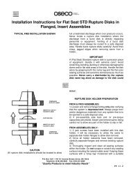
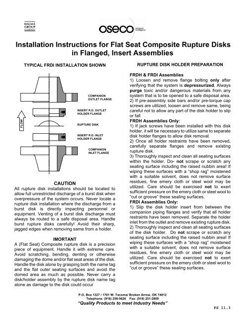
Installation Instructions for <strong>Flat</strong> <strong>Seat</strong> Composite Rupture Disks<br />
in Flanged, Insert Assemblies<br />
TYPICAL FRDI INSTALLATION SHOWN<br />
RUPTURE DISK HOLDER PREPARATION<br />
FLOW<br />
<strong>CO</strong>MPANION<br />
OUTLET FLANGE<br />
INSERT R.D. OUTLET<br />
HOLDER FLANGE<br />
RUPTURE DISK<br />
INSERT R.D. INLET<br />
HOLDER FLANGE<br />
<strong>CO</strong>MPANION<br />
INLET FLANGE<br />
CAUTION<br />
All rupture disk installations should be located to<br />
allow full unrestricted discharge of a burst disk when<br />
overpressure of the system occurs. Never locate a<br />
rupture disk installation where the discharge from a<br />
burst disk is directly impacting personnel or<br />
equipment. Venting of a burst disk discharge must<br />
always be routed to a safe disposal area. Handle<br />
burst rupture disks carefully! Avoid their sharp,<br />
jagged edges when removing same from a holder.<br />
IMORTANT<br />
A (<strong>Flat</strong> <strong>Seat</strong>) Composite rupture disk is a precision<br />
piece of equipment. Handle it with extreme care.<br />
Avoid scratching, bending, denting or otherwise<br />
damaging the dome and/or flat seat areas of the disk.<br />
Handle the disk alone by grasping both the name tag<br />
and the flat outer seating surfaces and avoid the<br />
domed area as much as possible. Never carry a<br />
disk/holder assembly by the rupture disk name tag<br />
alone as damage to the disk could occur<br />
FRDH & FRDI Assemblies<br />
1) Loosen and remove flange bolting only after<br />
verifying that the system is depressurized. Always<br />
purge toxic and/or dangerous materials from any<br />
system that is to be opened to a safe disposal area.<br />
2) If pre-assembly side bars and/or pre-torque cap<br />
screws are utilized, loosen and remove same, being<br />
careful not to allow any part of the disk holder to slip<br />
or fall<br />
FRDH Assemblies Only:<br />
1) If jack screws have been installed with this disk<br />
holder, it will be necessary to utilize same to separate<br />
disk holder flanges to allow disk removal.<br />
2) Once all holder restraints have been removed,<br />
carefully separate flanges and remove existing<br />
rupture disk.<br />
3) Thoroughly inspect and clean all seating surfaces<br />
within the holder. Do- not scrape or scratch any<br />
seating surface including the raised nubbin area! If<br />
wiping these surfaces with a “shop rag” moistened<br />
with a suitable solvent, does not remove surface<br />
residues, fine emery cloth or steel wool may be<br />
utilized. Care should be exercised not to exert<br />
sufficient pressure on the emery cloth or steel wool to<br />
“cut or groove” these sealing surfaces.<br />
FRDI Assemblies Only:<br />
1) Slip the disk holder insert from between the<br />
companion piping flanges and verify that all holder<br />
restraints have been removed. Separate the holder<br />
inlet from the outlet and remove existing rupture disk.<br />
2) Thoroughly inspect and clean all seating surfaces<br />
of the disk holder. Do not scrape or scratch any<br />
seating surface including the raised nubbin area! If<br />
wiping these surfaces with a “shop rag” moistened<br />
with a suitable solvent, does not remove surface<br />
residues, fine emery cloth or steel wool may be<br />
utilized. Care should be exercised not to exert<br />
sufficient pressure on the emery cloth or steel wool to<br />
“cut or groove” these sealing surfaces.<br />
P.O. Box 1327 / 1701 W. Tacoma/ Broken Arrow, OK 74012<br />
Telephone: (918) 258-5626 Fax: (918) 251-2809<br />
“Quality Products to meet Industry Needs”<br />
PS 11.3
Installation Instructions for <strong>Flat</strong> <strong>Seat</strong> Composite Rupture Disks<br />
in Flanged, Insert Assemblies<br />
RUPTURE DISK INSTALLATION<br />
disk.<br />
FRDH Assemblies Only:<br />
1) Place the rupture disk on the inlet flange of the<br />
rupture disk holder in a position that will allow system<br />
pressure to be exerted on the concave side of the<br />
rupture disk. This will allow the convex side (dome) of<br />
the rupture disk to extend away from the inlet flange<br />
and into the outlet flange of the rupture disk holder.<br />
2) Carefully position the outlet flange of the rupture<br />
disk holder over the dome of the rupture disk and<br />
lower same until seated on the flat surface of the<br />
rupture disk. If jack screws are being utilized, these<br />
must be “backed off” until the rupture disk holder<br />
flanges seat against the rupture disk. During this<br />
step, do not allow the rupture disk to slip from its<br />
position on the inlet flange. Damage will occur to the<br />
rupture disk if the outlet holder flange is seated on<br />
anything other than the flat surfaces (seating area) of<br />
the rupture disk.<br />
3) If pre-assembly side bars and/or pre-torque<br />
capscrews are utilized, install these items at this<br />
point.<br />
4) Reinstall studs, nuts and suitable gasketing.<br />
Tighten nuts uniformly to maintain flange surfaces<br />
parallel to one another. Always keep studs and nuts<br />
lightly lubricated to maintain a “free running”<br />
condition. The torque values listed in the table are<br />
suitable for many of the gasket and flange bolting<br />
materials currently in use. Please consult the factory<br />
when gasket sealing or a leak free rupture disk holder<br />
installation cannot be achieved or maintained. Do not<br />
use excessive torque on flange bolting as this may<br />
cause damage to the “bite” type seal in the holder as<br />
well as the rupture disk itself.<br />
FRDI Assemblies Only:<br />
1) Place the rupture disk on the inlet half of the<br />
rupture disk holder in a position that will allow system<br />
pressure to be exerted on the concave side of the<br />
rupture disk. This allows the convex side (dome) of<br />
the rupture disk to extend away from the inlet half of<br />
the rupture disk holder and into the outlet half.<br />
2) Carefully position the outlet half of the rupture disk<br />
holder over the dome of the rupture disk and lower<br />
same until seated on the flat surface of the rupture<br />
3) Install side bars; however, capscrews should only<br />
be snug, not wrench tight.<br />
4) Position FRDI/disk assembly within the bolt circle<br />
of companion piping flanges then reinstall studs, nuts<br />
and suitable gasketing. Tighten nuts uniformly to<br />
maintain companion flange surfaces parallel to one<br />
another. Always keep studs and nuts lightly<br />
lubricated to maintain a “free running” condition. The<br />
torque values listed in the table are suitable for many<br />
of the gasket and flange bolting materials currently in<br />
use. Please consult the factory when gasket sealing<br />
or leak free rupture disk holder installation cannot be<br />
achieved or maintained. Do not use excessive torque<br />
on flange bolting as this may cause damage to the<br />
"bite” type seal in the holder as well as the rupture<br />
disk itself.<br />
<strong>CO</strong>MPANION FLANGE TORQUE<br />
REQUIREMENTS FOR FLAT SEAT <strong>CO</strong>MPOSITE<br />
RUPTURE DISKS<br />
Size<br />
(inches)<br />
Companion Flange Torque<br />
(ft-lbs)<br />
150 ANSI 300 ANSI 600 ANSI<br />
1 20 25<br />
1.5 32 50<br />
2 49 25<br />
3 77 50<br />
4 52 65<br />
6 98 70<br />
8 131 105<br />
10 124 110<br />
12 200 155<br />
14 135<br />
16 350 195<br />
Please note that these torque values are based on<br />
carbon steel companion piping flanges, using B7<br />
studs and Flexatallic gaskets. For other flange<br />
materials, bolting or gaskets, adequate engineering<br />
judgment must be utilized to determine suitable<br />
torque values based on loads required to seal the<br />
P.O. Box 1327 / 1701 W. Tacoma/ Broken Arrow, OK 74012<br />
Telephone: (918) 258-5626 Fax: (918) 251-2809<br />
“Quality Products to meet Industry Needs”<br />
PS 11.3