Evaluation of Anechoic Chambers for EMC Measurements ... - EMCIA
Evaluation of Anechoic Chambers for EMC Measurements ... - EMCIA
Evaluation of Anechoic Chambers for EMC Measurements ... - EMCIA

You also want an ePaper? Increase the reach of your titles
YUMPU automatically turns print PDFs into web optimized ePapers that Google loves.
<strong>Evaluation</strong> <strong>of</strong> <strong>Anechoic</strong> <strong>Chambers</strong> For <strong>EMC</strong><br />
<strong>Measurements</strong> Using A CNE<br />
AN003<br />
Overview<br />
<strong>Anechoic</strong> chambers are used <strong>for</strong> <strong>EMC</strong><br />
testing primarily <strong>for</strong> radiated emissions (RE)<br />
and radiated immunity (RI) in the frequency<br />
range from 30MHz to 1GHz with extensions<br />
to 18GHz, or even 40GHz becoming more<br />
frequent.<br />
The chamber per<strong>for</strong>mance is dependent on a<br />
number <strong>of</strong> parameters as discussed below.<br />
In order to calibrate a chamber there are<br />
strict measurement procedures that should<br />
be followed, however it is possible to<br />
evaluate the chamber per<strong>for</strong>mance by a<br />
simple and quick measurement using a<br />
Comparison Noise Emitter (CNE).<br />
This application note presents results <strong>for</strong><br />
three chambers and clearly demonstrates<br />
the usefulness <strong>of</strong> the CNE <strong>for</strong> quickly<br />
evaluating chamber response. It also gives<br />
the reader an indication <strong>of</strong> what to look <strong>for</strong><br />
when analysing the results.<br />
Review <strong>of</strong> the CNE<br />
The CNE is a continuous broadband noise<br />
source, there are three models available with<br />
a usable output from 9kHz to 7GHz,<br />
applications include:<br />
• As a reference source <strong>for</strong> Radiated<br />
and Conducted measurement<br />
systems:<br />
o Daily pre-test checks<br />
o Long term per<strong>for</strong>mance<br />
monitoring<br />
o Cable position investigation<br />
• Investigation <strong>of</strong> measurement<br />
environments such as Open Area<br />
Test Sites (OATS), <strong>Anechoic</strong><br />
<strong>Chambers</strong>, Screened Rooms, GTEM<br />
Cells.<br />
• Characterising filter per<strong>for</strong>mance<br />
• Measuring cable losses<br />
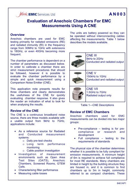
The units are battery powered so they can<br />
be operated without interconnecting cables<br />
affecting the measurements. Table 1 below<br />
describes the models available.<br />
CNE III<br />
9kHz to 2GHz<br />
Conducted and radiated output<br />
CNE V<br />
150kHz to 1GHz<br />
Conducted and radiated output<br />
CNE VII<br />
1.5GHz to 7GHz<br />
Radiated output only<br />
Table 1—CNE Descriptions<br />
Review <strong>of</strong> <strong>EMC</strong> <strong>Chambers</strong><br />
<strong>Anechoic</strong> chambers used <strong>for</strong> <strong>EMC</strong><br />
measurements can be divided into two major<br />
groups:<br />
• Pre-compliance – testing is <strong>for</strong> precompliance<br />
or research and<br />
development<br />
• Full compliance – testing to the<br />
requirements <strong>of</strong> standards<br />
The physical size <strong>of</strong> the chamber determines<br />
whether it is possible to be fully compliant <strong>for</strong><br />
emission measurements. A minimum height<br />
<strong>of</strong> 6m is required to achieve full compliance<br />
<strong>for</strong> most RE standards. Many chambers are<br />
limited in height by the building structure they<br />
are housed in, and it is common to find<br />
chambers up to 3m in height, commonly<br />
referred to as compact chambers. These<br />
8461AP1
Page 2<br />
AN003<br />
chambers can be fully compliant <strong>for</strong> RI<br />
measurements and are there<strong>for</strong>e found in<br />
accredited test laboratories where the RE<br />
measurements are made on an OATS. In<br />
this scenario the test chamber is generally<br />
used <strong>for</strong> pre-compliance RE testing or initial<br />
RE testing to determine the test plan <strong>for</strong> the<br />
OATS, it is there<strong>for</strong>e important to know the<br />
chamber characteristics even if full<br />
compliance is not achievable.<br />
Review <strong>of</strong> absorber technology<br />
An anechoic chamber used <strong>for</strong> <strong>EMC</strong><br />
measurements consists <strong>of</strong> an RF shielded<br />
room with RF absorber materials installed on<br />
the four walls and ceiling and possibly on the<br />
floor. There are 3 basic types <strong>of</strong> absorber:<br />
• Ferrite tiles – Useable frequency<br />
range 30MHz to 1GHz. Space<br />
efficient but heavy and cannot be<br />
used <strong>for</strong> high frequencies.<br />
• Hybrid absorber – Useable frequency<br />
range 30MHz to 18GHz. This<br />
combines ferrite tiles with microwave<br />
pyramidal foam. The foam must have<br />
a good impedance match with the<br />
ferrite.<br />
• Microwave pyramidal absorber –<br />
Useable frequency range 100MHz to<br />
18GHz. Low frequencies are limited<br />
by the depth <strong>of</strong> the absorber, <strong>for</strong><br />
example, a depth <strong>of</strong> 2.4m is required<br />
at 30MHz.<br />
Review <strong>of</strong> the CNE Response<br />
The broadband nature <strong>of</strong> the CNE output<br />
makes it ideal <strong>for</strong> observing any reflections in<br />
the chamber’s response and it becomes a<br />
useful tool <strong>for</strong> enabling a quick measurement<br />
to determine the acceptable frequency range<br />
<strong>of</strong> the chamber.<br />
The CNE output can be measured with or<br />
without an antenna; that is conducted or<br />
radiated. The conducted output is simply the<br />
CNE connected directly to a receiver as<br />
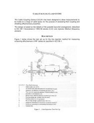
shown in figure 1. The radiated test set-up<br />
on an OATS is shown in figure 2. Typical<br />
plots <strong>for</strong> both tests are shown in figures 3<br />
Figure 1 – CNE III Direct Output<br />
and 4 respectively. <strong>Measurements</strong> were<br />
made using a Rohde and Schwarz ESVS30<br />
Receiver with a Resolution Bandwidth (BW)<br />
<strong>of</strong> 120kHz.<br />
Figure 2 – Typical Open Area Test Site<br />
Comparing the direct result with the OATS,<br />
above 300MHz there is a good correlation<br />
between the two, the radiated results have a<br />
higher amplitude variation due to the<br />
frequency response <strong>of</strong> the transmit and<br />
receive antennas and also the effect <strong>of</strong> the<br />
ground plane reflections. Below 300MHz the<br />
frequency response <strong>of</strong> the antennas is much<br />
more dominant and introduces significant<br />
losses due to the inefficiencies <strong>of</strong> the<br />
antennas in this frequency range, particularly<br />
the CNE transmit antenna.<br />
The response expected from a chamber<br />
should be similar to that <strong>of</strong> the OATS. If the<br />
absorber is not effective over the frequency<br />
range being tested reflections are<br />
introduced, which generate large ripples in<br />
the amplitude response making the chamber<br />
unusable.<br />
8461AP1
AN003<br />
Page 3<br />
100<br />
Amplitude dBmV<br />
90<br />
80<br />
70<br />
0 100 200 300 400 500 600 700 800 900 1000<br />
Frequency MHz<br />
Figure 3 - CNE III Direct Output<br />
90<br />
Horizontal<br />
Vertical<br />
80<br />
Field Strength dB mV/m<br />
70<br />
60<br />
50<br />
40<br />
30<br />
20<br />
0 100 200 300 400 500 600 700 800 900 1000<br />
Frequency MHz<br />
Figure 4 - CNE III Radiated Output @3m on an OATS<br />
Chamber per<strong>for</strong>mance using a CNE<br />
Three chambers were measured <strong>for</strong> the<br />
purpose <strong>of</strong> evaluation, table 2 lists their<br />
absorber type and size. All measurements<br />
are made at a 3m test distance.<br />
The following section shows the results <strong>for</strong><br />
the various chambers, the vertical plots only<br />
have been presented since the horizontal<br />
and vertical plots should be the same if the<br />
chamber is fully anechoic.<br />
Chamber<br />
reference<br />
Absorber<br />
Table 2<br />
Size m<br />
(L, W, H)<br />
Ch A Ferrite tiles 7.0, 3.5, 3.0<br />
Ch B<br />
Ch C<br />
Hybrid<br />
absorber<br />
Pyramidal<br />
foam<br />
6.7, 3.5, 4.0<br />
7.0, 4.0, 2.8<br />
8461AP1
Page 4<br />
AN003<br />
Test Set-Up<br />
The test set up <strong>for</strong> measurements up to<br />
1GHz is shown in figure 5<br />
Chamber<br />
3.0m<br />
ESVS30 Rx<br />
BW 120kHz<br />
RF Cable<br />
0.8m<br />
1.5m<br />
Antenna<br />
ChA, ChB CBL6140 X-Wing<br />
ChC CBL6112A Bilog<br />
Figure 5 - Test Set-Up <strong>for</strong> 30MHz to 1GHz<br />
Ch A Ch B Ch C<br />
90<br />
80<br />
Field Strength dBmV/m<br />
70<br />
60<br />
50<br />
40<br />
30<br />
20<br />
0 50 100 150 200 250 300<br />
Frequency MHz<br />
Figure 6 - 30MHz to 300MHz<br />
30MHz to 300MHz<br />
Figure 6 shows the results <strong>for</strong> the three<br />
chambers, Ch A & Ch B are very comparable<br />
in this frequency range. There is an unusual<br />
response from Ch C below 100MHz due to<br />
the inefficiency <strong>of</strong> the pyramidal absorber at<br />
these frequencies thus this chamber is not<br />
recommended <strong>for</strong> use below 100MHz.<br />
8461AP1
AN003<br />
Page 5<br />
30MHz to 1GHz<br />
Ch A has a higher<br />
ripple content compared<br />
to the other<br />
two chambers due to<br />
the ferrite tiles being<br />
less absorptive than<br />
the hybrid or pyramidal<br />
foam, however<br />
there are no sharp<br />
resonance’s and<br />
there<strong>for</strong>e the response<br />
<strong>of</strong> all three<br />
chambers is probably<br />
acceptable. Note:<br />
this only applies<br />
above 100MHz <strong>for</strong><br />
Ch C, see figure 7.<br />
Field Strength dBmV/m<br />
90<br />
80<br />
70<br />
60<br />
50<br />
40<br />
30<br />
20<br />
Ch A Ch B Ch C<br />
0 100 200 300 400 500 600 700 800 900 1000<br />
Frequency MHz<br />
Figure 7 - 30MHz to 1GHz<br />
Field Strength dBmV/m<br />
90<br />
80<br />
70<br />
Ch A Ch B Ch C<br />
60<br />
1000 1100 1200 1300 1400 1500 1600 1700 1800 1900 2000<br />
Frequency MHz<br />
Figure 8 - 1GHz to 2GHz<br />
<strong>Measurements</strong> made with HP8594E spectrum analyser, RBW<br />
100kHz, VBW 10kHz. Rx antenna: <strong>EMC</strong>O double ridged<br />
waveguide horn.<br />
1GHz to 2GHz<br />
Above 1GHz the ripple<br />
in Ch A response<br />
is much more dominant<br />
due to the inefficiency<br />
<strong>of</strong> the ferrite<br />
tiles in this frequency<br />
range and there<strong>for</strong>e<br />
this chamber is not<br />
recommended <strong>for</strong><br />
use above 1GHz. Ch<br />
B is starting to show<br />
an increase in the ripple<br />
but it is within an<br />
acceptable level. Ch<br />
C has a relatively<br />
smooth response and<br />
is a good choice in<br />
this frequency range.<br />
8461AP1
Page 6<br />
1GHz to 7GHz<br />
The ripple which was<br />
seen in figure 8 <strong>for</strong><br />
Ch B appears to improve<br />
again above<br />
a p proximately<br />
2.5GHz. It is unlikely<br />
that this is due to a<br />
poor match between<br />
the ferrite tiles and<br />
the hybrid foam but<br />
may indicate a low<br />
carbon content in the<br />
foam itself. In comparison<br />
Ch C still displays<br />
a relatively<br />
smooth response. Ch<br />
A was not measured<br />
over this frequency<br />
range.<br />
Field strength dBmV/m<br />
110<br />
100<br />
90<br />
80<br />
70<br />
60<br />
50<br />
Ch B<br />
Ch C<br />
1000 2000 3000 4000 5000 6000 7000<br />
Frequency MHz<br />
Figure 9 - 1GHz to 7GHz<br />
<strong>Measurements</strong> made using MS2663B spectrum analyser, RB/VB 1MHz<br />
AN003<br />
The standards do not currently have procedures<br />
<strong>for</strong> validating sites above 1GHz, although<br />
CISPR 16-2 is intended to cover this<br />
frequency range; in practice, chambers designed<br />
<strong>for</strong> working above 1GHz will <strong>of</strong>ten be<br />
validated using the Free Space Transmission<br />
Loss method. This method is essentially the<br />
NSA method with a few changes. The floor is<br />
fully or partially lined, antennas are calibrated<br />
in free space, the receive antenna is<br />
at a fixed height and the measured results<br />
are normalised to theoretical free space.<br />
Figure 10 -1 to 7GHz Test Set-up<br />
Standards<br />
Radiated emission requirements are covered<br />
by CISPR 16-1, this defines the Normalised<br />
Site Attenuation (NSA) validation method<br />
and criteria. This method is well known <strong>for</strong><br />
being probably the most difficult criteria <strong>for</strong><br />
any given chamber to pass. The NSA level <strong>of</strong><br />
the site must be within +/-4dB <strong>for</strong> measurements<br />
to be considered comparable to an<br />
OATS, however this method requires a<br />
ground plane <strong>for</strong> the frequency range 30MHz<br />
to 1000MHz and a height scan from 1 to 4m.<br />
Conclusions<br />
The results presented demonstrate the ease<br />
with which a CNE can be used to quickly verify<br />
the chamber characteristics. Although the<br />
chambers used in this article are all fully<br />
lined compact chambers the same technique<br />
can be used <strong>for</strong> partially lined screened<br />
rooms and GTEM cells.<br />
York <strong>EMC</strong> Services<br />
Tel: +44 (0)1904 434440<br />
Web: www.yorkemc.co.uk<br />
8461AP1