Mini Guide - EMCIA
Mini Guide - EMCIA
Mini Guide - EMCIA
- No tags were found...

Create successful ePaper yourself
Turn your PDF publications into a flip-book with our unique Google optimized e-Paper software.
<strong>Mini</strong> <strong>Guide</strong>REO-USA Inc8432 East 33rd Street,Indianapolis, IN46226-6550, USATel: 001 317 8991395 Fax: 001 317 8991396REO INDUCTIVE COMPONENTS AGBrühler Strasse 100, D-42657 Solingen, GermanyTel: 0049-(0) 2 12-88 04-0Fax: 0049-(0) 2 12-88 04-188REO (UK) LTD, Units 8-10 Long Lane Industrial EstateCraven Arms, Shropshire, SY7 8DUTel: +44 (0)1 588-673411 Fax: +44 (0)1 588-672718e-mail: sales@reo.co.uk website: www.reo.co.ukREO UK LTD
INTRODUCTION1CONTENTSINTRODUCTION 1EMC FILTERS 5HARMONIC FILTERS 10OUTPUT FILTERS 14BRAKING RESISTORS 18REOUNITY 20REO UK LTDThis booklet simplifies the powerquality issues relating to the choice,installation and running of variablespeed drives. It will help users,installers, specifiers and sales personnelto grasp important points andovercome potential or existingproblems, without having to readweighty technical publications,understand formulae or, for thatmatter, have a working knowledge ofelectrical engineering.How does an AC variablespeed drive work?To understand the applicationconsiderations associated with ACvariable speed drives, it is useful tobriefly examine how the drive operates.An AC Variable Speed Drive is moreproperly called an inverter but for ourpurposes we shall now refer to it as aVSD. The VSD comprises three maincomponents; a RECTIFIER, whichconverts the mains supply into DC, theDC LINK, which incorporates chokesand capacitors for maintaining a steadyDC voltage, and an OUTPUT STAGE,which uses Insulated Gate BipolarTransistors (IGBTs) for generating a3-phase, variable frequency output tocontrol the motor.The DC is switched on and off, typicallyat frequencies of 10 kHz. When aoscilloscope trace of the load current istaken, this approximates a sine wave,even though the voltage is a squareshape. This process is called pulsewidth modulation (PWM).Problems caused by VSDsUnfortunately, using a VSD is not assimple and trouble-free as it maysound. In many cases, the "powerconversion", together with theoperation of the motor itself, canpresent problems.Some readers may already be toofamiliar with a motor that runs too hot,is noisy, or in more extreme casesvibrates excessively leading to bearingfailure or total burn out. Any of theseconditions could be attributed toincorrect installation of a VSD. Othersmay have encountered nuisancetripping or VSD fault errors causedby unforeseen, application problems.Users may also be completely unawareof some of the other problems thata VSD may cause, as the effects maynot be seen in their own factory. Theseproblems include electromagneticinterference (EMI), radio frequencyinterference (RFI) or transients onthe line (spikes). We’ve all sat watchingour TV picture frizzle as the neighbouruses an electric drill. Well, in somecases your factory could be doing thatto an entire housing estate. Althoughyou may be unaware of any problems,
INTRODUCTIONINTRODUCTION2 3Diagramatical representation of anAC variable speed drive and the fourmain devices that will improvepower quality. These four types ofdevice are all found in REOUNITYdetails of which are on Page 20.the neighbours are getting restless.These phenomena are now governedby stringent regulations, includingEuropean Community directives, whichforce users to remedy any problems.Where are the problems?The problems faced by users of VSDscan be separated into three areas:those found on the input or supplyside, those between the VSD andthe motor, and those caused bythe operation of the motor itself.On the supply side there are twopotential problems to consider. Thefirst is everyday mains borneinterference and the other is harmonicdistortion. Between the VSD andthe motor, or on the output side ofthe VSD, the relatively high switchingfrequency of the VSD causes a steepvoltage rise time along the cable whichcan stress the motor for example.There are also a number of otherunseen (but in some cases can beheard) effects, such as greater motorlosses, radiated noise, higher leakagecurrents and undesirable current loopsthrough the motor shaft and bearings.Finally, in some instances, the motoritself may act as a generator andsend unwanted electrical power backdown the line.All these problems are potentiallydamaging but can be eradicatedrelatively simply using proprietaryequipment and a few words of advicefrom our later chapters. These willcover Electromagnetic Compliance(EMC), Harmonic Filters, Output Filtersand Braking Resistors.Why should I consider usinginput/output filters, reactorsand resistors?CostThese days everything seems to comedown to cost, even to the point ofignoring a short-term investment tomake a long term gain. Unfortunately,no VSD salesperson is going tojeopardise a sale by including extraequipment that does not providean immediate and obvious benefit, andno buyer is going to spend preciousbudget allocations on equipment thatdoes not increase production.However, what if it can be provedthat there are savings to be madeby installing a sinusoidal filter ratherthan fitting metres of expensive,screened, cable, or that motor life willbe extended and less production timelost by fitting a simple line reactor?SafetyWhen flying, you are asked not to usea mobile phone because it mayinterfere with the aeroplane’s electricaland electronic systems. In much thesame way, you are legally enforced to
INTRODUCTIONEMC FILTERS4 5ensure that your drive equipment willoperate without interfering with othersystems. You also have to ensure thatit has the ability to operate as intendedwithin a specified electromagneticenvironment, in other words that itwill not be affected by otherconforming equipment.The latest wave of EC Directives ensurethat equipment is built in accordancewith standards, that will makeit completely safe. This includes theLow Voltage, Machinery, EMC(Electromagnetic Compatibility)Directives, as well as, of course,the Health and Safety at Work Act.What’s more, in the next few years,the directives are being tightened upto spread the responsibility to theinstaller and the user. Installers willhave to satisfy themselves thatall installed switches, cables anddevices are compliant, and they willbe instructed to do so by the end user.Environmental regulationsThere is a proliferation of electronicequipment in the World today,contributing to the ambientelectromagnetic noise in theenvironment, or increasing the loadon the electrical supply network. Thehigh speed switching of semiconductorsin switch mode powersupplies, which includes drives, aswell as devices such as televisionsand computers, causes different typesof electrical disturbances on the mainssupply. Apart from the continuous"noise", harmonics are created bythe intermittent flow of currentthrough the electronic equipmentpowering the load. Unfortunately, theharmonics distort the mains sinewave, creating problems for thegenerating companies and thehigh frequency noise reduces theefficiency of the transmission cable inthe ground.To solve the problem, electricalcompanies could dig up every cablein the world and replace them withlarger ones. Or, the onus could beshifted to industry to ensure thatelectrical goods are designed, orinstalled, so that they do not produceharmonics.Consequently, the Electrical Association(power generators and local boards)has issued limits for acceptable levelsof harmonic distortion on the mainssupply. All consumers have to complyand larger plants have to seekapproval before they can beconnected to the supply. The newG5/4 recommendations specify themaximum harmonic levels that canbe accepted in the UK. Similarelectricity suppliers throughout the ECand the world also recognise theproblem and are introducing similarmeasures.One glance through the adverts in aSunday newspaper tells you that there’snow an electrical or electronic solutionfor almost all our needs. As well assolving all our domestic problems, fromour need to access the internet towearing a belt that turns Jimmy fivebelliesinto Jimmy six-pack, theproliferation of electrical and electronicdevices over the last few decades hasalso occurred in industry. Indeed, withincreasing automation in industry,there are very few applications whichdo not use electrical and electronicdevices!These days, it is also an increasinglycommon occurrence for energymanagement equipment to operatealongside control systems andinformation technology. Thus, it isinevitable that these items willinfluence each other's correctoperation, as a result of the electromagnetic interference (EMI) theygenerate. This interference, togetherwith radio frequency interference (RFI),can cause major problems from datacorruption and processor crashes toisolation breakdown.EMI, RFI and EMC explainedThe frequency of a normal AC line is 50Hz. EMI is caused when an externalforce like an electrical motor ortransformer varies the magnetic field,distorting the normal 50-cyclewaveform. RFI occurs when a highfrequency signal is superimposed overthe 50 Hz frequency, distorting thenormal waveform. Both EMI and RFIare commonly referred to as "noise".This noise can be external (from a radiostation, for example) or internal, frominside the equipment itself.The problem is that electrical noisecan disturb the regular operation ofelectrical and electronic equipment.For instance, if you own a computer,noise can scramble its output becauseit interferes with the transfer of datato modems, printers or hard disks.Noise also shows up as snow on TVscreens, or as "static" in stereosystems. In much the same way, thisnoise will affect the correct operationof a VSD.This interference can emanate in manydifferent forms and its source isfrequency dependent. Low frequencyinterference, under 10MHz, is usuallymains borne through isolated couplings.Higher frequency interference, over30MHz, is mainly radiated. The range inbetween these figures is caused by theaccumulation of transmission values.Most countries of the world haveregulations that cover the amount ofinterference a product generates, andthe amount of interference a productmust accept while still performing
EMC FILTERSEMC FILTERS6 7properly. This situation of causing littleinterference, and being immune tointerference from other sources isconsidered "compatibility", hence theterm "Electro-Magnetic Compatibility",or EMC.The limits for various interferencevoltages are specified in a number ofEuropean Standards, referred to as ENstandards. In these EN standards, adistinction is made between domesticand light industrial (Class B) andindustrial (Class A) applications.How do I preventelectromagnetic interference?The solution to preventing mains borneEMI and RFI interference, or noise, isto install an EMC filter on the supplyside of the VSD. These filters are usedto suppress, or attenuate, mainstransmitted interference. The filterswork by providing an impedancemismatch between the power lineand the equipment, which reflectsthe generated noise back to its source.As the filters operate in both directions,the interference from the supply tothe load and from the load to thesupply must both be attenuated.Selecting a FilterIdeally a filter should be built togive optimum performance with thesmallest number of components, orat least the most price effectivecomponents, to give the required levelof attenuation and safety.With differences between the varioustypes of interference, there is almostalways a combination of interferencecurrents which propagate withdiffering levels of intensity. Because ofthis, it may be necessary to specify afilter to suit an individual need.However, in many cases, theproprietary filters on the market aredesigned for universal application andcan be reliably applied.As a rule of thumb guide to choosing afilter, the most important point toconsider is the current rating. After this,the following criteria should beconsidered:●●●●●●●Allowable noise limits for theapplications, e.g. EN55011 Class APermissible maximum leakagecurrent values, as recognised byinternational standards authoritiessuch as the VDEMechanical protection againstcontact and water sprayLocal climatic conditions,including temperature andhumidity, and protectionrequirementsQuick and easy installationReduced mounting space,especially for footprint andbookcase filtersChoice of terminationsPower SurgesIt is not only electrical noise that can harm the correct operation of VSDs.When a lightning storm passes, we are all concerned that our domesticappliances won’t blow up as a result of a power surge. Although a lightningstrike is quite obvious, many transient surges, or spikes, are one-offmysterious events that cause equipment to malfunction without anyapparent reason. The causes of these surges are varied and can includeheavy appliances like refrigerators, furnaces and air conditionersautomatically turning their motors on and off, or power stations switchingelectrical loads. In the future, such surges originating with your servicecompany, many due to switching electrical loads and sources, will grow.The cost implications for VSD applications can be profound. For example, ifa multi-axis CNC machine, producing a very expensive turbine blade, isstopped, control is lost and the component may have to be scrapped or theprocess materials will be wasted.As a result, protection should always include a surge protection filter whichprotects equipment by generating a path to earth, when higher than normalsupply line voltages are present.What makes the filter work?The main components inside the filterare chokes, also known as inductors,capacitors and resistors. All of thesemust be matched to give theiroptimum filtering performance withinthe required frequency range of mainsborne interference (150kHz - 30kHz).The capacitors oppose the AC flow ofelectrons; more at lower frequenciesand less at higher frequencies. On theother hand, chokes react against therate of change of current and are moreeffective at opposing the AC flow ofelectrons at higher frequencies.Therefore, a combination of seriesconnected inductors and shuntconnected capacitors is chosen toprovide suppression over a widefrequency spectrum. The resistors serveto discharge the capacitors whenthe supply is disconnected and fordamping resonances. The enclosureis normally produced from metalto provide good earth bonding. Thefilter circuit is designed to contend
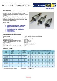
EMC FILTERS8EMC FILTERS9with two types of noise: COMMONMODE NOISE, which manifests itself asa current in phase in the live andneutral conductors and returns via thesafety earth, and DIFFERENTIAL MODENOISE produced by current flowingalong either the live or neutralconductor and returning by the other.To deal with both types of noise thechokes and capacitors used fall intotwo groups. Chokes consist of currentcompensated, or common mode,chokes and series, or differential mode,chokes. The capacitors consist of XClass and Y Class types, the formerbeing connected between live andneutral, or between phases, to reducedifferential noise, and the latterconnected between live/neutral andearth to reduce common mode noise.As a result of the different types ofinterference, a combination of Xcapacitors, Y capacitors, currentcompensated chokes and noncompensatedchokes are required.For higher levels of attenuation, severalstages of chokes and capacitors can beadded and this is known as a multistagefilter.Do I need combined orindividual attenuation?Sometimes it is possible to economiseby having a common filter system forseveral loads. In this way it is possibleto reduce the required number of filtersin a control panel. However, there areproblems in doing this:● It is difficult to introduce additionalcomponents at a later date● The rated current of the filterscannot be exceeded● Longer connection cables must bescreened● Loads are not filtered against eachother● Mutual interferences are notilluminatedFor these reasons, individual filters areusually the best solution.Installation and EffectivenessAfter the quality of the filter, the nextmost important factor in ensuring thatthe system works, is its installation. Shortcable runs and earth connect-ions to aflat surface can improve attenuation. Inorder to reduce radiated interference(approx. 10MHz-100MHz) one shouldalso fit ferrite rings on the input andoutput of the interference source.Another term frequently used to meanattenuation is 'insertion loss’, and inorder to test the effectiveness of aninstalled filter, damping characteristicdiagrams can be produced. These assesswhether a particular filter providessufficient suppression for a knowninterference pattern. Ultimately, preciseperformance can only be establishedby measurements, which should betaken at the output in order to providean accurate reflection of the levelof suppression.Leakage currentAnother important factor to consider isthe leakage current. This is the currentthat flows through the protectiveground conductor to ground. In usingEMC filters, as a result of the ACimpedence caused by the capacitors,an amount of AC leakage currentwill be caused. The larger the YClass capacitor, the more 50 Hzcurrent will leak to earthwhich raises the potential ofthe filter enclosure.Electrical equipmentcommonly includes agrounding system forprotection against a shockhazard if there is an insulationfailure. If such a failure occurs , thevoltage is shunted to ground, with theresulting current flow causing a fuse toblow or a circuit breaker to open,thereby preventing a shock hazard.Obviously, a possible shock hazardexists if the grounding connection isinterrupted, either intentionally oraccidentally. In VSD applications, usingEMC filters, it is therefore veryimportant to take into account theleakage currents as thesemay cause the shock hazard to begreater than supposed, therebynecessitating greater protection.The maximum permissible leakagecurrent depends on the application butto give an indication the maximumAbove: Typical EMC filter from REO,opened to show capacitors andchokes.earth leakage for double insulatedequipment, such as hedge trimmersand drills, is 0.25 mA. Equipment thatis permanently connected to the mainssupply may have a leakage current ofup to 5mA. Drives used in domesticapplications would normally require aleakage current of 1 - 2 mA but forindustrial applications 0.1% of therated current is permissible.
HARMONIC FILTERS10HARMONIC FILTERS11In the UK, new recommendationsrecently came into force relating toharmonics. The G5/4 Recommendationfrom the Electricity Council is muchmore than a mere recommendation inthat it encourages the electricitycompanies to get tough. As a result,they are now much more likely torefuse connection to new installationsthat return unduly high harmonics onthe line. This may seriously affectinstallations that include equipmentwith current rectification (a prime causeof harmonics), such as computers andvariable speed drives.What are harmonics?Understanding what is important toknow about harmonics can bechallenging for those without extensiveelectrical engineering backgrounds.The typical definition for a harmonic is"a sinusoidal component of a periodicwave or quantity having a frequencythat is an integral multiple of thefundamental frequency”. Somereferences refer to "clean" or "pure"power as those without any harmonics,but such clean waveforms typically onlyexist in a laboratory.Electrical generators try to produceelectric power where the voltagewaveform has only one frequencyassociated with it. This is theaforementioned fundamentalfrequency. In the UK this frequencyis 50 Hz. This means that fifty timesa second, the voltage waveformincreases to a maximum positive value,then decreases to zero, furtherdecreasing to a maximum negativevalue, and then back to zero. The rateat which these changes occur is thetrigometric function called a sine wave,as shown in diagram 1, opposite.The frequency of the harmonics aredifferent, but also dependent on thefundamental frequency. For example,the 2nd harmonic on 50 Hz is 2x50 or100Hz, the third harmonic is 3x50 or150Hz and so fourth. Diagrams 2 and3 show, the third and fifth harmonics.Diagram 4 shows the resultingdistortion to the 50Hz sine wave as itwould appear on an oscilloscope.The harmonics themselves are causedby:● saturable devices such astransformers and otherequipment using a magnetisingcurrent.● Arcing devices such as arcwelders and furnaces.● Power electronics such asvariable speed drives, diodes,SCRs and computers.Harmonic disharmonyOK, so we know what harmonics areand what can cause them but we nowneed to examine the problems theycause. Harmonics produced by one1234Take a 50 Hz sine waveAdd some third harmonicAdd in some fifth harmonicThe result is adistorted sine wave(shown in green)device can cause a variety of problemsin all the other equipment in a system.Such problems include excessiveheating in transformers and electricmotors, which can cause transformersto be derated, and excessive noiseand damage from increased motorvibration. Furthermore, capacitors cancause a resonant circuit whichmagnifies the harmonic current andleads to high voltage distortion,with the possibility of the capacitorsfailing through overheating.Other issues include: the impact oncommunications circuits throughinduction; meters having a tendencyto under-read; the failure of electronicequipment that uses the supply voltagewave form for switching; and themalfunctioning of equipment withsensitive loads that relies on asinusoidal wave form.In some electricity supply areas,harmonic pollution of the supply lineshas been a cause for concern forseveral years. The situation has beenexacerbated by the huge growth inthe use of computers and televisionsin domestic, commercial and industrialareas. This has driven the tougherlegislation and it is clearly thecommercial and industrial applicationsthat are most likely to be policed.
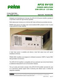
HARMONIC FILTERSHARMONIC FILTERS12 13Rules & RegulationsThe harmonic solutionThe Engineering RecommendationG5/3 has been in place for a decadeand a half and has provided certainguidelines. These include limits ofharmonic current that can be fed intothe system by customers, limits forharmonic distortion caused,suggestions for whether a load can beconnected and procedures formeasurement and assessment of newloads.The new G5/4 is more stringent thanits predecessor, requiring more carefulassessment of new loads andmeasurements to be taken at differentvoltage levels. It also extends the rangeof harmonics covered and includesinterharmonics and notching currents.The issue extends into Europe too. TheBSEN 50160 covers voltagecharacteristics of supply systems thatare now part of the Grid Code. Thisstandard also indicates that themaximum total harmonic voltagedistortion must be no more than 8%.The European standard is less stringentthan G5/4, but it must be rememberedthat G5/4 still applies!By now, you have probably got themessage that harmonics are a seriousproblem and cannot be ignored for avariety of practical and legislativereasons.In identifying the problem, probablyone of the toughest tasks is takingmeasurements. However, analyserinstruments are available for purchase,or hire, and quite a few specialists willmake assessments for you. Actuallyremedying harmonics is in most casessimply a matter of fitting the correctfilters.One of the easiest, most practical andcommon solutions is to install linereactors. These devices introduce animpedance that reduces the root meansquare (RMS) and peak voltages whileat the same time improving the powerfactor. It is possible to combine such areactor with a conventional filter in asingle unit, thereby providingattenuation for the mains borneinterference and compliance with theEMC Directive (an earlier enactedlegislation covering electro magneticand radio frequency interference). Byincorporating both of these necessitiesin a single housing, valuable panelspace is saved and wiring is minimised.13Figures 1 to 3: The oscilloscope tracesshow the effects on the 50 Hz sinewave of introducing a line reactorand a combined filter and reactor.Figure 1 shows the oscilloscope traceof the original output with a 7.7ARMS and 24.5A peak.Figure 2 shows the effects of theintroduction of a 4% impedance linereactor which reduces RMS to 4.8Aand gives a peak of 9.5A.Figure 3 shows the effects of acombined filter and reactorwhich produces a cleansine wave as well asreducing the currentdistortion.Left: The CNW304, atypical motor choke andmains filter combinationunit from REO.2
OUTPUT FILTERSOUTPUT FILTERS14 15Those engineers that long associatedthe application of AC inverters withvariable speed motor control are likelyto remember the early days wheninverters were frequently blamed forburning out motors. In most cases, theVSDs were rightly accused. Today,most AC induction motors are betterinsulated and built to withstandthe stresses placed on them throughthe use of VSDs, but there are stillgood reasons for fitting output filtersto the VSDs.Essentially, what happens at the outputside of the VSD depends on a numberof factors. The capacitive coupledconductors of the motor can beinduced with very high load currents bythe VSD. Cable run lengths affect thisinduction, as does the power rating ofthe system and the switchingfrequency of the drive. In the last case,the stresses are intensified, with mostmodern inverters switching at everincreasing speeds, using the latestgeneration isolated gate bipolartransistors (IGBTs).The problemIt is the rate of rise time in the dV/dtcurve - or to put it a simpler way, thecombination of rapid voltage andcurrent increase - that stresses theconductors and the motor, bothelectrically and mechanically.Consequently, the insulation of themotor windings is in turn stressedby the internal, energy-laden,components, as well as externalvibration. The durability of componentsis reduced and, if the motor is old, thiscan cause faults in the motor assembly,such as partial discharge occuringin the insulation material. This leads topremature failure of the motor.Although modern motors maywithstand this effect, it does nothing toprolong their lifetimes!To understand what happens, onemust consider what is happeningwithin the drive. In the simplest terms,most modern inverters use pulse widthmodulation (PWM) technology that12uses pulses to digitally emulate the ACsine wave. It is these pulses, generatedby the high frequency IGBT switchesthat are the problem. Oscilloscopetraces show very clearly that, whenswitched voltage pulses are outputfrom the drive's IGBTs, there is aresultant current spike as the cablesbecome energised. It is, as we statedbefore, the rapid voltage rise time, inconjunction with the voltage peaksthat creates the stresses on the motor,or a reflected current spike causing theinverter to shut down.The degree of the rapid rise time andhence the amount of stress on themotor is also directly affected by cable34Figures 1 to 4: The traces show a VSDdriving a motor, with no mechanicalload, a 50m cable run and 8kHzswitching frequency. Figure 1 is atrace taken at the drive end withCH1 (top trace) showing an outputvoltage of 500V/div and CH2 (bottomtrace) an output current of 12.5A/div.Looking closer, in figure 2, CH1shows the switched voltage pulsesand CH2 the current spikes, as thecable becomes energised. Figure 3shows the rapid rise time and figure4 shows a close up of this voltagerise at the motor terminals wheredV/dt is equal to 1400V/m s.length. The longer the cable length theworse the condition.The cable to the motor has to be veryquick in transferring potential butthis leads to an excessive, capacitiveload current. With lengthy cable runsthis can be very high and hasa negative influence on the dynamicregulation system of the inverter until itshuts down for protection reasons.Transient, high voltages with a rise rateof 3 to 6 kV/m s originate from longercable runs and consequently the motorinsulation can be
OUTPUT FILTERSOUTPUT FILTERS16 17overloaded many times over.Furthermore, these days, screenedcable is used to connect the motor inorder to comply with the EMCDirective. However, this screening alsocontributes to the voltage rise becauseof the stray capacitance effect of thescreen.The solutionThe dV/dt can be reduced in severalways, with varying degrees ofeffectiveness that are cost related.These choices include:●●●●●Output chokes for dV/dt limitingOutput chokes for dV/dtattenuationOutput chokes with conventionalconstructionEnclosed output chokesSinus filtersdV/dt limiting chokesAs described previously, inverters, bythe nature of their operation, generatea strong asymmetric component. ThedV/dt choke dampens theseasymmetric interference currents,without weakening the usefulsymmetrical current. Moreover, theEMC interference of between 1 and30MHz is significantly reduced. This isan economical solution suitable forinstallation in control panels usingelectronic components, because thechoke produces a very small stray field.dV/dt attenuating chokesThis type of output choke suppressesrapid voltage rises, by virtue of itsconstruction, to acceptable levels thatare recommended for asynchronousmotors in VDE 0530. Consequently,the output choke prevents high voltagetransients over longer cable runs. Itscompact construction simplifiesinstallation and improves theappearance of a control panel. Thesmall volume and dimensions meanthat the output choke has less losses incomparison with conventional outputchokes.Output chokes -conventional constructionThe conventional output choke has agood storage capacity. It works like atypical line inductor and smooths thesymmetrical effective current as well asthe asymmetrical interference current.The voltage increase is limited to lessthan 500V/m s. The voltage spikesbetween conductors at the motorterminal rail are smaller than 1000V.This solution provides goodsuppression of mains conductedinterference in the lower frequencyrange. Electomagnetic emissions fromthe cable are very heavily damped. Thelosses and typical noise from the motordrive, caused by ripple are reduced.Enclosed output chokesBuilding a conventional filterinto an IP22 enclosure has theadvantage of providing safetyprotection and also helps toreduce the possibility of a firehazard from hot components.The separate input and outputports, together with precisedimensions, improve theaesthetics of the control panellayout.Sinus filterThe sinusoidal filter operates like alow pass filter. It changes the switchingvoltage pulses back to a sinusoidal form.The running and loss balancing of theasynchronous motor are the same asfor normal mains operation. The typicalmotor whistling noise from an inverterdrive is no longer apparent becausethe phase current is now also sinus.There is a trade-off of comfortableoperation of the motor against thelosses of the filter. A screened cable tothe motor is no longer required,depending on the application.Above: The CNW933 ouput chokefrom REO which dampens theasymmetric interference currentsgenerated by VSDs, withoutweakening the useful symmetricalcurrent.
BRAKING RESISTORSBRAKING RESISTORS18 19So, we’ve dealt with all the EMCrequirements, we’ve sorted theharmonics and we’ve eliminatedcurrent spikes. No more problems -right? Wrong! At the end of this book,and also at what could be called theend of the line, is the motor itself whichcan act as a generator and sendelectrical energy back down the line tothe VSD.When unavoidable rotational velocitychanges, or braking under load, causesthe frequency of the motor to exceedthat of the inverter, the motor operateslike a generator and develops energy.Typically a major proportion of thisenergy is converted by the motor intoelectrical power and returned to thevariable speed drive. In someapplications, such as in lifts and hoistswhere a high-inertia load is deceleratedin a short time, the power returned bythe motor may be too great for the DCbus of the variable speed drive toabsorb. As a result, a DC bus overvoltagetrip may occur.The simplest way to prevent the DCvoltage rising, and therefore causingovercharging of the DC bus capacitorbank, is to convert the motorgenerated energy into heat by usingbraking resistors.In drive systems, the braking resistor isconnected into the DC link, betweenthe input rectifier and the switchingstagewhich converts the DC into avariable frequency output to drive themotor. Therefore, to save energy, it isdesirable to use the resistor in such away that it only switches-in when it isreally needed, instead of beingpermanently connected.The braking resistor is normallycontrolled through a chopper circuit,which monitors the DC link voltagethrough a sensor. When the DC voltageexceeds a preset level, a powersemiconductor is used to switch thebraking resistor into circuit.This discharges the DC capacitors andthe DC voltage drops to a lower presetlevel, causing the braking resistor to beswitched out of the DC link circuit.Most modern drives up to 32A havethe chopper circuit built in as standard.A separate chopper card is used forhigher current ratings.The power rating of a braking resistor isdetermined by the required brakingtime and the period of rest in betweenbraking operations. Usually theduration of braking is short and duringthis time the energy is stored in theform of heat, which is subsequentlytransferred to the environment duringthe rest time. The duty cycle (ED) isdetermined by dividing the brakingor "on" time by the total cycle time(on time plus rest time) and expressingthis as a percentage (%).Opposite Page: REO’s range ofbraking resistors for VSDs includesfootprint, panel mounting, highpower and compact versions. Witha compact construction, the entireseries offers easy installation.
REOUNITY2021The simple one box solutionfor frequency drivesSo, in operating our VSD, we’ve cometo the conclusion that we need to cleanup the sine wave, limit current spikes,reduce rapid rise times eliminateelectromagnetic interference anddissipate regenerated energy. That’s alot of work to be done, a lot ofaccessories and a lot of extra wiring.And we thought installing a VSD wassimple.Fortunately, this simplicity can beretained, as REO has developed arevolutionary modular system forfrequency drives. Named REOUNITY,not only does this new unit make lifeeasier for panel builders but it alsolowers costs.REOUNITY is an all-in-one system whichincorporates all ancillary driveequipment into a standardised unit, toprovide an entire power-conditioningpackage. REOUNITY fulfils all the EMC,power factor correction and energyabsorption needs encountered intoday's drive engineering applications.For added convenience, REOUNITYtakes the bookcase format used bymost drive manufacturers. For anyindividual application REOUNITYincludes all the necessary EMC filters,braking resistors, motor chokessinusoidal filters, and dV/dt filters,packaged to provide commondimensions for a particular current orpower rating. The components fittogether, side by side, for optimum useof panel space. The use of high qualitycomponents, such as amorphous cores,throughout the range, reduces lossesand weight.Panel Builders benefit from simplifiedpanel layouts and position changing ofcomponents, and the simple additionof extra components in the controlpanel if needed. At present the rangeextends from 6A (2kW) to 34A (15kW)although higher power ratings areplanned.REOUNITY: One box fits all.REO was founded in 1925 and manufactures a range of products used inmedium-voltage power systems. We specialise in custom designs ofcomponents and sub-assemblies, catering to both small and large orders.In other words we build what our customers want.We have a wealth of experience in the manufacture of wound components ontocylindrical and toroidal cores. We are also conversant with the latest electricalstandards and the use of modern production methods. Most importantly, as theoriginal manufacturer, we are able to offer our customers the very best pricesbecause they are buying from source.By using the best quality materials and the optimum choice of components, weensure that the most compact and price effective solutions are provided. REO alsoprovides unified modules for a complete range of accessories, saving space, wiringtime, build time and providing a consolidated, finished product that has anengineered appearance.Most of our products are supplied off-the-shelf and we are happy to build samplesor to test our customers’ equipment for compliance.For more information about the REO product range visit:www.reo.co.uk.