You also want an ePaper? Increase the reach of your titles
YUMPU automatically turns print PDFs into web optimized ePapers that Google loves.
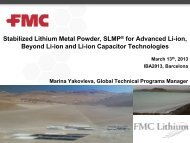
A “Gold Rush” for High Energy<br />
Batteries <br />
<strong>John</strong> <strong>Muldoon</strong><br />
Toyota Research Institute of North<br />
America
Moving Away From Alloys: Towards Metal Anodes<br />
9<br />
8<br />
Abundance<br />
(ppb)<br />
log<br />
7<br />
6<br />
5<br />
4<br />
3<br />
2<br />
1<br />
0<br />
Li Na K Be Mg Ca Zn Al<br />
Li Na K Be Mg Ca Zn Al<br />
MW<br />
(g/mol)<br />
Density<br />
(g/cm 3 )<br />
6.94 23.0 39.1 9.01 24.3 40.1 65.4 27.0<br />
0.53 0.97 0.86 1.85 1.74 1.55 7.14 2.7<br />
A magnesium anode is very attractive due to high capacities, reductive potential<br />
and abundance in the earth crust
Reduction at the Anode: the SEI<br />
Li +<br />
Li +<br />
Mg 2+ Mg 2+<br />
Mg 2+<br />
Li + Li SEI conducts Li<br />
+<br />
Passivating layer<br />
+<br />
X<br />
Li/C<br />
Mg<br />
• In contrast to Li, an SEI (solid‐electrolyte interface) on Mg precludes the<br />
use of many electrolytes.<br />
• Reversible Mg deposition can be observed in Grignard‐based electrolytes,<br />
first shown by Overcash and Mathers in 1933.<br />
Overcash, D. M.; Mathers, F. C. Trans. Electrochem. Soc. 1933, 64, 305.<br />
Gregory, T. D.; Hoffman, R. J.; Winterton, R. C. J. Electrochem. Soc. 1990, 137, 775‐780.<br />
Lu, Z.; Schechter, A.; Moshkovich, M.; Aurbach, D. J. Electroanal. Chem. 1999, 466, 203‐217.
Deposition at the Magnesium Anode<br />
Highly dependent on<br />
electrolyte<br />
Lithium<br />
SEM resolution: 5000X<br />
Deposition rate: 2.0 mAcm −2<br />
Magnesium<br />
SEM resolution: 5000X<br />
Deposition rate: 2.0 mAcm −2<br />
Mg is less<br />
reductive than Li =><br />
• Mg does not form SEI in ether solvents<br />
• Mg does not form dendrites<br />
Dey, A.N.; Sullivan, B.P. J. Electrochem. Soc. 1970, 117, 222<br />
Matsui, M., J Pow. Sou. 2011, 196, 7048–7055<br />
Gregory, T.D.; Hoffman, R.J.;Winterton, R.C. J. Electrochem. Soc. 1990, 137, 775
Mg Battery with Mg Organohaloaluminate Electrolytes<br />
Anode: Mg metal<br />
Cathode: Mg x Mo 3 S 4<br />
Electrolyte: in situ generated Mg organohaloaluminate 2:1 Bu 2 Mg : AlClEt 2<br />
• First demonstration of rechargeable Mg battery system:<br />
•Proven >2000 cycle with
Roadblocks Towards a High Energy Magnesium Battery<br />
Q<br />
<br />
/<br />
vol <br />
<br />
V<br />
(<br />
q<br />
)<br />
dq<br />
/<br />
vol<br />
[<br />
WhL<br />
0<br />
1 ]<br />
Increase voltage<br />
Increase capacity<br />
1) 2e ‐ transfer to the same metal center<br />
dilithium in Li 2 NiO 2 , LiVSe 2 /Li 2 VSe 2<br />
2) Facile solid state diffusion of magnesium in the cathode<br />
3) High voltage, non‐corrosive electrolyte<br />
Whittingham, S., Chem. Rev., 2004, 104, 4271‐4301.<br />
Dahn, J.R, U. von Sacken, Michal, C.A, Sol. State. Ion., 1990, 44, 87‐97.
In Situ Generated Mg Organohaloaluminates<br />
Black: 1:2 Bu 2 Mg and EtAlCl 2<br />
Red: 1:2 AlCl 3 and PhMgCl<br />
Bu 2 Mg + 2 EtAlCl 2<br />
THF<br />
Crystallization product was electrochemically inactive when re-dissolved in THF.<br />
Aurbach, D et al, Nature, 2000, 407, 724‐727.<br />
Aurbach, D et al, Chem. Record 2003, 3, 61‐73.<br />
Aurbach, D et al, Adv. Mater., 2007, 19, 4260‐4267.
Crystallization of 1 st Generation Electrolyte<br />
+<br />
Si<br />
THF<br />
O<br />
N<br />
Si + AlCl 3<br />
OMg<br />
24 hrs<br />
MgCl<br />
O<br />
Cl<br />
Cl<br />
Cl<br />
O<br />
Mg<br />
O<br />
O<br />
Si Si<br />
N Cl<br />
Al<br />
Cl Cl<br />
HMDSMgCl<br />
Kim, H.S.et HSetal. Nat. Commun. 2:427 doi: 10.1038/ncomms14351038/ncomms1435 (2011) .
Electrochemistry of crystal<br />
crystal<br />
In situ<br />
electrolyte<br />
HMDSMgCl<br />
Formation of (Mg 2 (μ-Cl) 3·6THF)[(HMDS)AlCl 3 ]<br />
HMDSMgCl + AlCl 3<br />
→ MgCl + + HMDSAlCl 3<br />
-<br />
Transmetallation (1)<br />
2HMDSMgCl HMDS 2 Mg + MgCl 2 Schlenk equilibrium (2)<br />
MgCl + + MgCl 2<br />
Mg 2<br />
Cl 3<br />
+<br />
(3)<br />
3HMDSMgCl + AlCl 3<br />
→ Mg 2<br />
Cl 3+ + HMDSAlCl 3- + HMDS 2<br />
Mg (4)<br />
• Transmetallation is key reaction in the formation of the product<br />
• (Mg 2 (μ-Cl) 3·6THF) is the electrochemically active species
The Role of Frontier Orbitals in Electrochemistry of Electrolytes<br />
Oxidation is the loss<br />
of electron to HOMO<br />
orbital<br />
(eV)<br />
Energy<br />
Lowest Unoccupied<br />
Molecular Orbital (LUMO)<br />
Highest Occupied<br />
Molecular Orbital (HOMO)<br />
Reduction is the addition<br />
of electron to LUMO<br />
orbital<br />
• Reductive stability may be predicted by calculating LUMO energy value<br />
•Oxidative stability may be predicted by calculating HOMO energy value<br />
More negative HOMO energy → higher oxidave stability<br />
More posive LUMO energy → higher reducve stability
DFT Prediction of Electrochemical Properties<br />
Table 1 Summary of HOMO and LUMO energy levels for the anion component of the<br />
crystallized electrolytes. 20<br />
Electrolyte Anion HOMO (eV) LUMO (eV)<br />
1<br />
2<br />
J , mA/cm 2<br />
*(HMDS) 2 AlCl 2<br />
-<br />
(HMDS)AlCl 3<br />
-<br />
15<br />
10<br />
5<br />
0<br />
-5<br />
--- ---<br />
-5.670 0.061<br />
Ph - 4 Al -5384 -5.384 0182 0.182<br />
Ph 3 AlCl - -5.678 0.047<br />
Ph 2 AlCl 2<br />
-<br />
1 1.5 2 2.5 3 3.5 4 4.5<br />
E , V vs Mg<br />
-6.045 0.058<br />
•Based on this logic, our DFT<br />
calculations predict the<br />
electrolyte order of oxidative<br />
stability to be 4>2>1>3.<br />
•Based on the assumption that<br />
the HOMO energy level gap<br />
between the (HMDS)AlCl 3‐ and<br />
(HMDS) 2 AlCl 2‐ anions is similar to<br />
the energy gap between PhAlCl ‐<br />
3<br />
and Ph 2 AlCl 2‐ anions.<br />
-<br />
Fig. 5 Linear PhAlCl scan 3 voltammograms -6.402 depicting typical -0.062 voltage stability of (Mg 2 (μ-<br />
Cl 4 Al - -6.742 -1.384<br />
Cl) 3·6THF)(HMDS n AlCl 4-n ) (n=1,2) (blue), (Mg 2 (μ-Cl) 3·6THF)(Ph n AlCl 4-n ) (n = 1 – 4)<br />
(turquoise), (Mg 2 (μ-Cl) 3·6THF)(BPh 4 ) (red) and (Mg 2 (μ-Cl) 3·6THF)[B(C 6 F 5 ) 3 Ph] (green)<br />
3 Ph 4 B - -4.819 -0.536<br />
on a Pt working electrode with a surface area of 0.02 cm 2 . Scan rate for all scans is 25<br />
mV s -1 ; magnesium reference and counter electrodes are used at a temperature of 21 °C.<br />
4 (C 6 F 5 ) 3 BPh - -5.559 -0.422<br />
*The structural flexibility of (HMDS) 2 AlCl 2 - makes its geometry difficult to optimize.
Problem Charging in a 2025 Coin Cell<br />
• why cannot charge above 22V 2.2V<br />
•voltage stability of gen1 on Pt working electrode (w. e.) is 3.2V
Voltage Stabilities of Gen 1 on Various Working Electrodes<br />
20<br />
15<br />
SS Ni Pt C Au<br />
A B<br />
2<br />
J , mA/cm<br />
10<br />
5<br />
0<br />
-5<br />
1.5 2 2.5 3 3.5 4 4.5<br />
E vs Mg, V<br />
SEM of stainless steel before (A) and after (B)<br />
exposure to 1 st generation electrolyte for 1 week<br />
• Crystallized magnesium organohaloaluminates are corrosive in nature
Voltage Stabilities for Gen 2 Electrolyte<br />
m 2<br />
mA/c20<br />
J ,<br />
mA/cm 2<br />
J ,<br />
30<br />
20<br />
10<br />
0<br />
-10<br />
Pt working electrode<br />
1.25 1.75 2.25 2.75 3.25 3.75<br />
15<br />
E , V vs Mg<br />
SS working electrode<br />
10<br />
5<br />
0<br />
-5<br />
1.25 1.75 2.25 2.75 3.25 3.75<br />
E , V vs Mg<br />
3PhMgCl + BPh 3 → [Mg 2 Cl 3+ ][BPh4 ‐ ] + Ph 2 Mg<br />
No pitting observed<br />
• Causes an improvement of 400 mV in voltage stability<br />
•Anion has dramatic effect on corrosion<br />
<strong>Muldoon</strong>, et al, Energy and Environ. Sci., 2012. 5, 5941
Voltage Stabilities for Gen 3 Electrolyte<br />
235<br />
25<br />
15<br />
5<br />
-5<br />
J , mA/cm 2<br />
235<br />
25<br />
, mA/cm 2<br />
J<br />
15<br />
5<br />
-5<br />
Pt working electrode<br />
1 2 3 4 5<br />
E , V vs Mg<br />
SS working electrode<br />
Hysteresis<br />
0 1 2 3 4 5<br />
E , V vs Mg<br />
3PhMgCl + B(C 6 F 5 ) 3 → [Mg 2 Cl 3+ ][B(C 6 F 5 )Ph 3‐ ]+ Mg(C 6 F 5 ) 2<br />
•1.0V improvement in voltage stability on Pt w.e. : 3.7V<br />
• Corrosion on SS limits potential window to 2.2V<br />
Corrosion observed<br />
<strong>Muldoon</strong>, et al, Energy and Environ. Sci., 2012. 5, 5941
Chlorine Free Magnesium Organoborates<br />
Mixture and Filter<br />
BPh 3 +Bu 2 Mg (BPh 3 Bu) 2 Mg Soluble in THF 0.4M<br />
(BPh 3 Bu)2Mg (gen 4) THF
Electrolyte Preparation by Ion Switching<br />
gen3<br />
On SS316<br />
gen1<br />
gen2<br />
genX<br />
genX<br />
• Solubility of genX is >0.5M in glyme<br />
• Chlorides Are the Culprit of Corrosion<br />
• Its reductive stability must be improved<br />
<strong>Muldoon</strong> et al, Energy Environ. Sci., 2013, 6, 482–487
Membrane Encapsulated Sulfur Cathodes<br />
membrane<br />
0.1C ‐ membrane<br />
Blue: 1C – membrane<br />
Black: 1C –non‐membrane<br />
Red: 5C – membrane<br />
Improved lifetime and C – rates on encapsulation with a<br />
selective membrane
Conclusions<br />
Anion structure as well as<br />
combination between cation<br />
and anion strongly gyaffected<br />
the oxidation stability and<br />
corrosion of the electrolyte.<br />
There is a need for<br />
developing high dielectric<br />
solvents with a higher<br />
reductive stability such that<br />
they are compatible with Mg