

2000 PROGRESS REPORT - ENEA - Fusione
2000 PROGRESS REPORT - ENEA - Fusione
2000 PROGRESS REPORT - ENEA - Fusione

You also want an ePaper? Increase the reach of your titles
YUMPU automatically turns print PDFs into web optimized ePapers that Google loves.
1. Magnetic Confinement<br />
After completion of the vacuum<br />
tests, setup of the power supplies<br />
and of all the electrical<br />
connections, re-building of a new<br />
cooling system and preliminary<br />
formation of the plasma in the<br />
duoPIGatron source, the system is<br />
ready for operation.<br />
The characterization of the beam<br />
quality will be initially based on<br />
optical observations of its intrinsic<br />
emission and on infrared<br />
observations of a target hit by the<br />
beam itself.<br />
Fig. 1.14 - Overall view of the vacuum chamber containing the neutral<br />
source<br />
Development of diagnostics. a)<br />
MSE. The beam attenuation and<br />
the brightness of the main Stark<br />
component expected in a discharge<br />
with a 1020 m-3 average<br />
electron density are shown in<br />
fig. 1.16. The figure also reports<br />
the radial dependence of the<br />
polarization angle to be measured.<br />
Laboratory test of the Photoelastic<br />
Modulators (PEM) [1.10]<br />
polarimeter on a laser source have<br />
yielded the desired accuracy of the<br />
polarimeter angle (0.1°). The PEM<br />
frequencies (40/46 kHz) and fast<br />
data acquisition (5 Ms/s) will<br />
allow for time resolution of a few<br />
ms on the MSE measurements.<br />
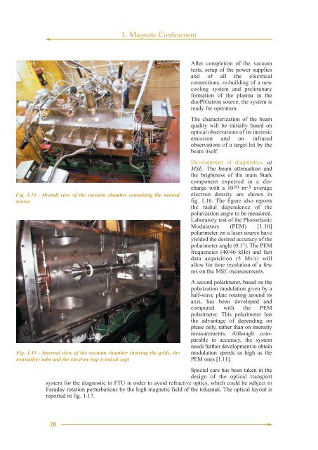
Fig. 1.15 - Internal view of the vacuum chamber showing the grids, the<br />
neutraliser tube and the electron trap (conical cup)<br />
A second polarimeter, based on the<br />
polarization modulation given by a<br />
half-wave plate rotating around its<br />
axis, has been developed and<br />
compared with the PEM<br />
polarimeter. This polarimeter has<br />
the advantage of depending on<br />
phase only, rather than on intensity<br />
measurements. Although comparable<br />
in accuracy, the system<br />
needs further development to obtain<br />
modulation speeds as high as the<br />
PEM ones [1.11].<br />
Special care has been taken in the<br />
design of the optical transport<br />
system for the diagnostic in FTU in order to avoid refractive optics, which could be subject to<br />
Faraday rotation perturbations by the high magnetic field of the tokamak. The optical layout is<br />
reported in fig. 1.17.<br />
20


