

2000 PROGRESS REPORT - ENEA - Fusione
2000 PROGRESS REPORT - ENEA - Fusione
2000 PROGRESS REPORT - ENEA - Fusione

You also want an ePaper? Increase the reach of your titles
YUMPU automatically turns print PDFs into web optimized ePapers that Google loves.
1. Magnetic Confinement<br />
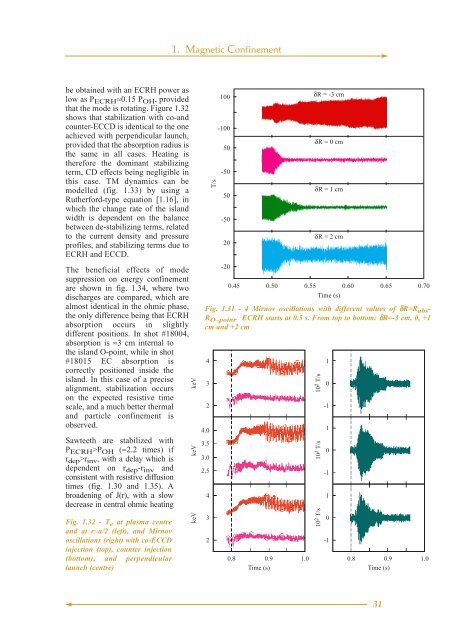
be obtained with an ECRH power as<br />
low as P ECRH ≈0.15 P OH , provided<br />
that the mode is rotating. Figure 1.32<br />
shows that stabilization with co-and<br />
counter-ECCD is identical to the one<br />
achieved with perpendicular launch,<br />
provided that the absorption radius is<br />
the same in all cases. Heating is<br />
therefore the dominant stabilizing<br />
term, CD effects being negligible in<br />
this case. TM dynamics can be<br />
modelled (fig. 1.33) by using a<br />
Rutherford-type equation [1.16], in<br />
which the change rate of the island<br />
width is dependent on the balance<br />
between de-stabilizing terms, related<br />
to the current density and pressure<br />
profiles, and stabilizing terms due to<br />
ECRH and ECCD.<br />
The beneficial effects of mode<br />
suppression on energy confinement<br />
are shown in fig. 1.34, where two<br />
discharges are compared, which are<br />
almost identical in the ohmic phase,<br />
the only difference being that ECRH<br />
absorption occurs in slightly<br />
different positions. In shot #18004,<br />
absorption is ≈3 cm internal to<br />
the island O-point, while in shot<br />
#18015 EC absorption is<br />
correctly positioned inside the<br />
island. In this case of a precise<br />
alignment, stabilization occurs<br />
on the expected resistive time<br />
scale, and a much better thermal<br />
and particle confinement is<br />
observed.<br />
Sawteeth are stabilized with<br />
P ECRH >P OH (≈2.2 times) if<br />
r dep >r inv , with a delay which is<br />
dependent on r dep -r inv and<br />
consistent with resistive diffusion<br />
times (fig. 1.30 and 1.35). A<br />
broadening of J(r), with a slow<br />
decrease in central ohmic heating<br />
Fig. 1.32 - T e at plasma centre<br />
and at r≈a/2 (left), and Mirnov<br />
oscillations (right) with co-ECCD<br />
injection (top), counter injection<br />
(bottom), and perpendicular<br />
launch (centre)<br />
keV keV keV<br />
T/s<br />
100<br />
-100<br />
50<br />
-50<br />
50<br />
-50<br />
20<br />
-20<br />
δR = -3 cm<br />
δR = 0 cm<br />
δR = 1 cm<br />
δR = 2 cm<br />
0.45 0.50 0.55 0.60 0.65 0.70<br />
Time (s)<br />
Fig. 1.31 - 4 Mirnov oscillations with different values of δR=R abs -<br />
Fig. 1.31<br />
R O–point . ECRH starts at 0.5 s. From top to bottom: δR=-3 cm, 0, +1<br />
cm and +2 cm<br />
4<br />
3<br />
2<br />
4.0<br />
3.5<br />
3.0<br />
2.5<br />
4<br />
3<br />
2<br />
0.8 0.9 1.0<br />
Time (s)<br />
10 2 T/s<br />
10 2 T/s<br />
10 2 T/s<br />
1<br />
0<br />
-1<br />
1<br />
0<br />
-1<br />
1<br />
0<br />
-1<br />
0.8 0.9 1.0<br />
Time (s)<br />
Fig. 1.32<br />
31


