Product Catalog - Conteg
Product Catalog - Conteg
Product Catalog - Conteg

Create successful ePaper yourself
Turn your PDF publications into a flip-book with our unique Google optimized e-Paper software.
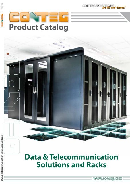
Data & Telecommunication Solutions and Racks ver. 25<br />
<strong>Product</strong> <strong>Catalog</strong><br />
CONTEG SOLUTIONS<br />
for the next decade!<br />
Data & Telecommunication<br />
Solutions and Racks<br />
www.conteg.com
CONTENTS<br />
ABOUT <strong>Conteg</strong> 3<br />
History 4<br />
Warranty 5<br />
1. TOTAL SOLUTIONS<br />
6<br />
FOR DATA CENTERS<br />
1.1 Modular Closed Loop 8<br />
1.2 Contained Cold Aisle 10<br />
1.3 Contained Hot Aisle 12<br />
1.4 Hot/Cold Aisle 14<br />
1.5 Plenum Feed with Room 16<br />
Return<br />
1.6 Room Feed with Plenum 18<br />
Return<br />
1.7 Services 20<br />
1.8 TestCenter for Data Centers 22<br />
1.9 AEGIS Data Center<br />
24<br />
Infrastructure<br />
Management<br />
1.10 CFD Modeling 25<br />
2. FREE-STANDING RACKS 26<br />
PREMIUM Rack Series 27<br />
2.1 PREMIUM Heavy RHF 28<br />
2.2 PREMIUM Cabling RDF 32<br />
2.3 PREMIUM Server RSF 36<br />
2.4 PREMIUM Rack Series 40<br />
Plates<br />
2.5 PREMIUM Housing RSB 42<br />
OPTIMAL Rack Series 44<br />
2.6 OPTIMAL ROF 45<br />
2.7 OPTIMAL Flex RMF 50<br />
2.8 Special OPTIMAL 55<br />
OPTIMAL PC ROP<br />
OPTIMAL Twist ROR<br />
OPTIMAL Cable Management<br />
iSEVEN Rack Series 58<br />
2.9 iSEVEN Ri7 59<br />
2.10 iSEVEN Flex RM7 63<br />
Open Frames, Space Optimization<br />
68<br />
Sections, Extrusions<br />
2.11 Open Frames RSG4 68<br />
2.12 Open Frames RSG2 69<br />
2.13 Open Frames RS 70<br />
2.14 Space Optimization<br />
71<br />
Section<br />
2.15 Extrusions 73<br />
3. WALL-MOUNT & SOHO RACKS 74<br />
3.1 Wall-Mount PREMIUM RUN 75<br />
3.2 Wall-Mount PREMIUM Split 76<br />
RUD<br />
3.3 Wall-Mount OPTIMAL RON 77<br />
3.4 Wall-Mount OPTIMAL Split 78<br />
ROD<br />
3.5 Wall-Mount iSEVEN REN 79<br />
3.6 SOHO In-Wall 80<br />
3.7 SOHO On-Wall 81<br />
3.8 SOHO Mini REH 82<br />
4. CABLE MANAGEMENT 84<br />
4.1 High Density Wire<br />
85<br />
Management<br />
4.2 OptiWay 89<br />
4.3 Top Duct 94<br />
4.4 Standard Cable<br />
Management<br />
99<br />
5. TARGETED COOLING &<br />
101<br />
AIRFLOW MANAGEMENT<br />
5.1 CoolTeg Cooling Units 102<br />
5.2 CoolSpot Cooling Units 106<br />
5.3 Ventilation Units 109<br />
Fans, Active Doors<br />
5.4 Airflow Management 111<br />
products<br />
Contained Aisle – Fixed and<br />
Modular Solution<br />
Air Separation Frame<br />
Blank Panels<br />
Air Flow Deflector<br />
Vented Panels<br />
5.5 S-T-S Airflow Support 113<br />
6. COMPLEMENTARY SYSTEMS 114<br />
6.1 RAMOS - Rack Monitoring 115<br />
Systems<br />
RAMOS Ultra<br />
RAMOS Optima<br />
RAMOS Mini<br />
6.2 Access Control System 121<br />
6.2 KVM/LCD Solutions 122<br />
6.3 Local Extinguishing Systems 123<br />
6.4 Intelligent & Basic Power 124<br />
Distribution Units<br />
Basic Power<br />
Intelligent Power Monitored<br />
Intelligent Power Managed<br />
7. ACCESSORIES 128<br />
7.1 Shelving 129<br />
Fixed Shelves, Pull-Out<br />
Shelves, Drawers and<br />
Holders, Supporting Rails<br />
7.2 Fiber-Optic <strong>Product</strong>s 131<br />
Fiber-Optic Splice Boxes,<br />
Wall-Mount Fiber-Optic<br />
Splice Boxes<br />
7.3 Patch Panels 134<br />
7.4 Earthing Bar 134<br />
7.5 Modular Plinths 135<br />
7.6 Castors & Feet 137<br />
7.7 Mounting & Connecting 137<br />
Kits<br />
7.8 Others 138<br />
Wall-Mount Holders<br />
Protection of Cable<br />
Openings, Lighting Unit<br />
8. outTEG 139<br />
8.1 outTEG outdoor cabinets 140<br />
Index 141<br />
QUALITY AND ENVIRONMENTAL COMMITMENTS<br />
<strong>Conteg</strong>, spol. s r.o. provides TÜV certificates for its products and follows strict<br />
ISO 9001 quality & ISO 14001 environment protection standards.<br />
WARRANTY<br />
<strong>Conteg</strong>, spol. s r.o. provides a 24-month warranty on all products unless otherwise<br />
stated. A 12-month warranty is applicable on CoolTeg, CoolSpot, LES-RACK, outdoor<br />
cooling units, outdoor air/air heat exchangers and filter fans.<br />
2
ABOUT CONTEG<br />
<strong>Conteg</strong> is one of the leading producers of racks and data center solutions in EMEA. In our product portfolio, you can find<br />
telecommunication and data racks, complete solutions for data centers, and outdoor cabinets. Our solutions include freestanding<br />
& wall-mounting racks, precision cooling, cable management, intelligent power distribution & environmental<br />
monitoring systems, as well as a wide range of accessories.<br />
:: about <strong>Conteg</strong><br />
<strong>Conteg</strong> Headquarters:<br />
Na Vítězné pláni 1 719/4<br />
140 00 Prague 4<br />
Czech Republic<br />
Our innovative and modular products and solutions are in line with<br />
current industry trends. Their quality and functionality can be endorsed<br />
by our global customers. They are used throughout the IT industry when<br />
deploying servers, UPS and other components and to manage structured<br />
cabling systems both inside and outside the racks.<br />
Our core values include:<br />
• Innovativeness<br />
• Responsibility and flexibility<br />
• Continuous technical support<br />
• Quality service<br />
• Trust<br />
• Experienced and friendly staff<br />
• Top-quality products at competitive prices<br />
• Saving you time<br />
<strong>Conteg</strong> <strong>Product</strong>ion Facilities and Central Warehouse:<br />
K Silu 2 179<br />
393 01 Pelhřimov<br />
Czech Republic<br />
<strong>Conteg</strong> is based in the Czech Republic and its products satisfy customer<br />
needs across the whole Europe, Africa, and Asia – from United Kingdom<br />
to Saudi Arabia to Bangladesh and from Finland to France to South Africa.<br />
A wide network of distribution partners covers more than 50 countries<br />
which means <strong>Conteg</strong> products are always close to you – ready to be shipped<br />
and installed. Many countries are also covered by local branch offices with<br />
permanent staff.<br />
Local Branches and Showrooms:<br />
Austria, Vienna<br />
Czech Republic, Prague<br />
France, Paris<br />
India, Bangalore<br />
Russia, Moscow<br />
The Netherlands, Breda<br />
United Arab Emirates, Dubai<br />
www.conteg.com 3
History<br />
Our journey from simple racks to complete data center solutions<br />
1998 - one type of free-standing rack<br />
1999 - new series of free-standing rack RSV; wall-mount rack RSD; basic accessories assortment<br />
2000 - new series of free-standing rack ROV<br />
2001 - new series SOHO REH, wall-mount RON; wall-mount ROD<br />
2002 - new series wall-mount REN<br />
2003 - new series of free-standing rack REV<br />
2004 - new series wall-mount RUN, wall-mount RUD<br />
2005 - new series of free-standing rack ROF<br />
2006 - new series of free-standing rack RSL<br />
2007 - new series of free-standing rack ROS; free-standing rack RMF; development of data center solutions<br />
2008 - new series in/on wall-mount rack ACP; KVM/LCD; Targeted Cooling; development of data center solutions finalized<br />
2009 - new series iSEVEN free-standing rack; facelift of free-standing rack ROF; wall-mount RON and wall-mount ROD series;<br />
Total Solutions for Data Centers<br />
2010 - new free-standing rack series - PREMIUM; Side Mount Closed Loop Solutions<br />
2011 - construction of a new multi-purpose building at the factory in Pelhřimov; CoolTeg XC units; AEGIS DCIM system; facelift RMF rack, Modular Closed<br />
Loop architecture<br />
2012 - opening of new multi-purpose building and TestCenter for Data Centers in Pelhřimov. New products: outdoor cabinet outTEG series, OPTIMAL<br />
Cable Management rack, Side-to-Side Airflow Support - STS, EC technology fans for cooling, Rack Monitoring Systems – RAMOS Ultra,<br />
Optima & Mini, upgrades made to OptiWay, new HDWM, new PDUs, new Separation Frames, Mounting & Connecting Kits<br />
2013 - new cooling units CoolTeg Plus; facelift of PREMIUM Housing RSB rack; New products: PDU brackets, Top Ducts - cable management system<br />
:: history<br />
4<br />
TestCenter for DataCenters<br />
4
Warranty<br />
Emphasis on Quality<br />
Quality is our priority, therefore we do everything to ensure that our<br />
products are among the best available on the market, matching the<br />
services provided by our company. We aim to provide our customers with<br />
the highest possible added value. For this reason, we apply strict ISO 9 001<br />
quality management standards at <strong>Conteg</strong>. All racks undergo a strict testing<br />
regime to obtain TÜV certification.<br />
<strong>Conteg</strong> products are meticulously built from quality materials which<br />
comply with technical and environmental specifications and are thoroughly<br />
tested and inspected prior to leaving our manufacturing facility. You can<br />
be assured that when purchasing a <strong>Conteg</strong> product you have selected<br />
a product of the highest quality and reliability.<br />
:: warranty<br />
Warranty & Return Policy<br />
<strong>Conteg</strong> products are warranted against defects in material and<br />
workmanship for a specific period from the date of shipment. In most cases,<br />
the warranty period is two (2) years and covers replacement parts only.<br />
CoolTeg and CoolSpot cooling units, LES-RACK fire extinguishing device<br />
and outdoor condensing units have standard warranty period of one (1)<br />
year from the date of shipment from <strong>Conteg</strong>’s warehouse. Exception to this<br />
warranty period is when customer purchases Start-up service from <strong>Conteg</strong><br />
or from one of <strong>Conteg</strong>’s local partners. Under these conditions the warranty<br />
period commences on the given Start-up date. During the warranty period,<br />
<strong>Conteg</strong> will, at its discretion, provide replacement parts or replace products<br />
that prove to be defective. Repairs are warranted for the remainder of the<br />
original warranty or a 90 day extended warranty, whichever is longer. The<br />
warranty period for all <strong>Conteg</strong> products can be extended under individual<br />
conditions, which must be agreed upon with <strong>Conteg</strong>.<br />
For equipment under warranty, the owner is responsible for freight to<br />
<strong>Conteg</strong> and all related customs duties, taxes, tariffs, insurance, etc. <strong>Conteg</strong><br />
is responsible for the freight charges only for return of the equipment<br />
from the factory to the owner in cases when the warranty claim has been<br />
accepted. All equipment returned for warranty repair must have a valid<br />
RMA number issued prior to return and be marked clearly on the return<br />
packaging. <strong>Conteg</strong> strongly recommends all equipment be returned in its<br />
original packaging. <strong>Conteg</strong>’s obligations under this warranty are limited<br />
to repair or replacement of failed parts, and the return shipment to the<br />
buyer of the repaired or replaced parts. <strong>Conteg</strong>'s delivery deadline for any<br />
replacement parts shall not exceed a period of 1 month. When “Spare Parts<br />
in Stock” service is purchased <strong>Conteg</strong> will guarantee instant warehouse<br />
availability of all needed parts.<br />
In order to assure quality installation of CoolTeg cooling units all customers<br />
have option to purchase Start-up services by <strong>Conteg</strong>. <strong>Conteg</strong> can also<br />
arrange post-warranty service provided either by <strong>Conteg</strong>’s qualified<br />
employees or by <strong>Conteg</strong>‘s local contractual partners.<br />
Limitations of Warranty<br />
The warranty does not apply to any part of a product that has been installed,<br />
altered, repaired, or misused in any way that, in the opinion of <strong>Conteg</strong>,<br />
would affect the reliability or detracts from the performance of any part of<br />
the product, or is damaged as the result of use in a way or with equipment<br />
that had not been previously approved by <strong>Conteg</strong>. The warranty does<br />
not apply to any product or parts thereof where the serial number or the<br />
serial number of any of its parts has been altered, defaced, or removed. The<br />
warranty does not cover damage or loss incurred in transportation of the<br />
product.<br />
The warranty does not cover replacement or repair necessitated by loss or<br />
damage from any cause beyond the control of <strong>Conteg</strong>, such as lightning<br />
or other natural and weather related events or wartime environments.<br />
The warranty does not cover any labor involved in the removal and or<br />
reinstallation of warranted equipment or parts on site, or any labor required<br />
to diagnose the necessity for repair or replacement. The warranty covers<br />
products and/or parts only. No service or labor related costs are included<br />
under the <strong>Conteg</strong> warranty.<br />
www.conteg.com 5
1. TOTAL SOLUTIONS<br />
FOR DATA CENTERS<br />
1. TOTAL SOLUTIONS<br />
6<br />
FOR DATA CENTERS<br />
1.1 Modular Closed Loop 8<br />
1.2 Contained Cold Aisle 10<br />
1.3 Contained Hot Aisle 12<br />
1.4 Hot/Cold Aisle 14<br />
1.5 Plenum Feed with 16<br />
Room Return<br />
1.6 Room Feed with 18<br />
Plenum Return<br />
1.7 Services 20<br />
1.8 TestCenter for Data 22<br />
Centers<br />
1.9 AEGIS Data Center 24<br />
Infrastructure<br />
Management<br />
1.10 CFD Modeling 25<br />
:: total solutions for data centers<br />
6
8<br />
MODULAR CLOSED LOOP<br />
10<br />
CONTAINED COLD AISLE<br />
:: total solutions for data centers<br />
12<br />
CONTAINED HOT AISLE<br />
14<br />
HOT/COLD AISLE<br />
18<br />
ROOM FEED WITH PLENUM RETURN<br />
16<br />
PLENUM FEED WITH ROOM RETURN<br />
www.conteg.com 7
1.1 MODULAR CLOSED LOOP<br />
42U+<br />
Modular Closed Loop offers the ability to achieve up to 35 kW of cooling power per rack per assembly. This type of<br />
architecture can be especially useful when planning to install a few very high-power racks into a facility since the racks<br />
do not release any heat into the data center environment. It is also an ideal solution when limited rack space (for example,<br />
in atypical server room of a mid‐size company) is required, but cooling becomes an issue because of the high-density<br />
applications housed there.<br />
Modular Closed Loop architecture is based on<br />
CoolTeg units from the Targeted Cooling range<br />
and racks from the PREMIUM Server portfolio.<br />
Cool air is generated by the CoolTeg unit(s) and<br />
delivered into the cold zone in the front part of<br />
rack(s), where it is close to the equipment cooling<br />
intake. The hot exhaust air from the equipment<br />
is then removed from the hot zone in the rear<br />
part of the rack(s) by the CoolTeg unit(s), cooled<br />
and delivered back into the cold zone, forming<br />
a closed recycling air loop. This architecture<br />
ensures that heat generated within the cabinet<br />
is removed at the point of production and not<br />
released into the data center or server room<br />
environment, thereby minimizing the chances<br />
of localized hotspots forming in high-density<br />
zones.<br />
Closed Loop architecture is available in<br />
a modular design, where virtually an unlimited<br />
number of racks and cooling units can be<br />
combined into a closed module. The modular<br />
design is fully flexible and accommodates<br />
any combinations of cooling units<br />
and racks to meet the required<br />
levels of cooling and<br />
redundancy.<br />
It is pre-designed for<br />
PREMIUM Server racks that are<br />
1200 mm deep, 600 or 800 mm wide and<br />
42, 45 or 48U high as well as for CoolTeg units<br />
that are 1200 mm deep, 300 mm or 400 mm wide<br />
and 42, 45 or 48U high.<br />
Illustrative image only<br />
The Modular Closed Loop solution is very<br />
energy efficient, especially when CoolTeg Plus<br />
units are connected to chiller with free-cooling<br />
technology.<br />
MODULAR CLOSED LOOP DESIGN GUIDELINES<br />
:: modular closed loop<br />
The Closed Loop can include a virtually unlimited number of PREMIUM Server racks and cooling units. However, six racks (252 – 288U) should be the limit<br />
when considering the standard layout of data center applications. The configuration of the rack differs according to its position in the module – please be<br />
aware of it when planning the module. All racks are delivered fully assembled with the requested passive airflow management already installed (separation<br />
frames). Both cooling unit versions, chilled water (CW) as well as direct expansion (XC, DX), are available to provide the module with needed cooling power<br />
of up to 35 kW per cooling unit. The module can be easily designed in fully redundant mode. The Modular Closed Loop can be configured according to the<br />
needs of any customer and can be anytime in the future modified and fitted at a later date with additional racks and cooling units.<br />
• Typically for heat loads of up to 35 kW per cabinet<br />
• 42U to 48U – 600 mm or 800 mm wide cabinets – 1 200 mm deep<br />
• Air separation frames – 200 mm deep<br />
• Front glass door<br />
• Solid rear door<br />
• No raised floor required<br />
• Double brush grommets for cable entries<br />
• Blanking panels for all vacant equipment mounting locations in cabinets<br />
• Monitoring of cabinet's interior environmental conditions<br />
• IP54 protection recommended<br />
• Solution is also applicable outside the clean data halls<br />
Protection rating IP54, load rating PREMIUM<br />
Server – 1 500 kg, color black RAL 9005<br />
(optionally light gray RAL 7035). Separation<br />
frame and sealing. For detailed technical<br />
information on PREMIUM Server racks please<br />
refer to page 36. CoolTeg Cooling Unit with top<br />
or bottom piping. Piping and outdoor chiller are<br />
not a standard parts of this product. For more<br />
information about CoolTeg cooling units please<br />
refer to page 102.<br />
8
Cooling unit code 2<br />
Description<br />
Modular Closed Loop RACKS<br />
Middle rack code End‐of‐the‐row rack code Description<br />
RSF‐42‐60/12T‐GWSWM‐MCL RSF‐42‐60/12T‐GWSWN‐MCL RSF Modular Closed Loop Rack 42U x 600×1 200<br />
RSF‐42‐80/12U‐GWSWM‐MCL RSF‐42‐80/12U‐GWSWN‐MCL RSF Modular Closed Loop Rack 42U x 800×1 200<br />
RSF‐45‐60/12T‐GWSWM‐MCL RSF‐45‐60/12T‐GWSWN‐MCL RSF Modular Closed Loop Rack 45U x 600×1 200<br />
RSF‐45‐80/12U‐GWSWM‐MCL RSF‐45‐80/12U‐GWSWN‐MCL RSF Modular Closed Loop Rack 45U x 800×1 200<br />
RSF‐48‐60/12T‐GWSWM‐MCL RSF‐48‐60/12T‐GWSWN‐MCL RSF Modular Closed Loop Rack 48U x 600×1 200<br />
RSF‐48‐80/12U‐GWSWM‐MCL RSF‐48‐80/12U‐GWSWN‐MCL RSF Modular Closed Loop Rack 48U x 800×1 200<br />
Add ‐E at the end of the rack’s code for having emergency opening system (EOS) pre‐installed; EOS includes 4 electronic latches, specially<br />
reinforced door with multipoint lock, gas struts; RAMOS Mini unit recommended for operation (not part of delivery)<br />
Modular Closed Loop COOLING UNITS 1<br />
AC-TDX-42-30/120-BCD Direct Expansion, 20 kW, 42U x 300×1 200 3<br />
AC-TCW-42-30/120-BCD Chilled Water, 35 kW, 42U x 300×1 200<br />
AC-SM-XC/B4-42-40/120 Integrated compressor, 26 kW, 42Ux400×1 200<br />
Drain pump can be mounted and connected to the unit to remove condensate out of the unit in case of no raised floor<br />
1 Plinth is not a part of delivery<br />
2 Modular Closed Loop cooling units in 45U and 48U heights available upon request<br />
3 Different cooling power available depending on the type of outdoor unit AC-DX-XXXXX (ordered separately)<br />
:: modular closed loop<br />
RELATED PRODUCTS<br />
Emergency Opening System automatically<br />
opens the front and rear doors of the racks<br />
in case the cooling unit fails to prevent the<br />
overheating of equipment inside the rack. The<br />
problem is detected by the RAMOS monitoring<br />
system (not a standard part of the Emergency<br />
Opening System) which sends an alarm message<br />
to the Emergency Opening System to prevent<br />
possible damage to the equipment. However,<br />
the best protection is provided by having a fully<br />
redundant module configuration.<br />
Local Extinguishing System<br />
LES‐RACK is a self‐contained, fully automatic<br />
fire detection and protection system. Designed<br />
for installation directly into 19" racks with<br />
protection rating IP30 or higher. It offers<br />
a very secure and effective solution for server,<br />
telecommunication and control racks/cabinets.<br />
LES‐RACK‐M comes with a fully equipped<br />
automatic system of fire detection, control,<br />
evaluation and extinguishing unit.<br />
Note: Cooling capacity for this configuration can reach higher values, depending on how many variables there are,<br />
including capacity and other features of the precision computer room cooling unit, like the ratio of supply air space to<br />
return plenum space and the amount of air obstructions in the supply and return air spaces.<br />
www.conteg.com 9
1.2 CONTAINED COLD AISLE<br />
252U+<br />
:: contained cold aisle<br />
The <strong>Conteg</strong> Contained Cold Aisle solution physically separates cold and hot zones. One of the potential drawbacks of the<br />
no-containment Hot/Cold Aisle approach is the possibility of warm air recirculation due to insufficient static pressure within<br />
the raised floor or a lower than optimal ceiling clearance preventing adequate stratification of warm air. Of course, whether<br />
this actually occurs or not depends on many variables; however when facing this type of design challenge, it makes engineering<br />
and financial sense to form a physical barrier between cold and warm air streams.<br />
With the <strong>Conteg</strong> Contained Cold Aisle (CCA)<br />
solution, a containment system is used to<br />
physically separate cold air from hot exhaust by<br />
forming a cold plenum space that prevents hot<br />
and cold air from mixing, thereby eliminating hotspots.<br />
The cold air is supplied into the contained<br />
aisle through perforated tiles from the raised<br />
floor or produced locally by CoolTeg units, which<br />
are installed directly in the row of cabinets as an<br />
integral part of the aisle. The standard width of<br />
the CCA is 1.2 m (two perforated tiles) or 1.8 m<br />
(three perforated tiles). Other widths are available<br />
- 1.0 and 2.4 m. CCA can be deployed with<br />
standard swing doors or dual leaf sliding doors.<br />
Using the Contained Cold Aisle solution is highly<br />
recommended to maximize the cooling efficiency<br />
and minimize the energy consumption of the<br />
entire data center.<br />
The system is designed to work with the<br />
RSF/RDF/RHF/RSB/ROF rack series, the basis of<br />
<strong>Conteg</strong>'s data center solutions. It supports racks<br />
that are 42U, 45U or 48U high.<br />
Roof<br />
The modular roof sections are bolted onto the<br />
top of the racks to prevent the mixing of cold air<br />
and warm exhaust air. The roof parts are 400, 600,<br />
800, 900 and 1 100 mm long. The roof panels are<br />
made of 6 mm thick clear polycarbonate panels<br />
that allow light to spill into the contained aisle.<br />
This material is non-flammable according to the<br />
By using the roof, the cold air is “trapped” in the<br />
contained aisle. The roof also efficiently blocks the<br />
hot air from re‐entering the aisle.<br />
local codes. Our solution allows an extinguishing<br />
system to be installed to the aisle.<br />
Door sections<br />
CCA entry is through one or two doors that<br />
are either 1200 mm or 1800 mm wide. The door<br />
is a very important component of this contained<br />
aisle solution. There are two solutions – a sliding<br />
or swing door. Both types consist of two doors<br />
(wings). A standard sliding door consists of<br />
a mechanical opening system (each door wing<br />
is independent) and can be equipped with<br />
a dual synchro system (both door wings move<br />
simultaneously) or with an automatic system<br />
with electric control. Sliding doors are made from<br />
aluminium.<br />
As standard, the dual leaf swing door is<br />
mechanical and can be equipped with an<br />
Automatic door handle system. A blank panel<br />
Sliding doors allow access to the contained aisle. They can<br />
be equipped by mechanical, dual synchro or automatic<br />
handling systems.<br />
could be used instead of a door to close one side<br />
of the contained aisle.<br />
CONTAINED AISLE - MODULAR SOLUTION<br />
The Modular Contained Aisle system is the<br />
ideal solution when rows of racks with different<br />
heights or even gaps (when some racks are<br />
missing) need to be to contained. The system<br />
is based on self-supporting construction with<br />
clear polycarbonate panels on the top of the<br />
roof. Vertical side sections of the roof feature<br />
PVC foil strips. These strips can be easily cut to<br />
the required length. The Modular Contained<br />
Aisle can work with standard dual leaf swing<br />
doors or with PVC foil strips (see below) instead<br />
of standard doors. This solution can be used with<br />
cabinets that are 2 300 mm or 2 500 mm tall. Do<br />
not hesitate to contact us for more information.<br />
10
COOLING<br />
In the Contained Cold Aisle design, cold air is produced by a central<br />
cooling system with perimeter-mounted CRAC/CRAH units. The raised<br />
floor is used as a cold air handling plenum and the cold air enters the aisle<br />
via perforated floor tiles. If for any reason the raised floor cannot be used,<br />
the cold air can be produced locally by in-row CoolTeg units that can be<br />
installed directly in the row of racks. This solution is currently very popular<br />
as it can address very high heat loads and is energy efficient.<br />
RECOMMENDED RACK SERIES<br />
Rack Description Read more<br />
PREMIUM Server RSF PREMIUM rack series, highly configurable with load rating up to 1500 kg 36<br />
PREMIUM Cabling RDF<br />
PREMIUM rack series provides maximum compatibility with Targeted Cooling solutions and is developed for<br />
cabling support; load rating up to 500 kg<br />
32<br />
PREMIUM Heavy RHF PREMIUM rack series provides ultra high load rating up to 1500 kg 28<br />
OPTIMAL ROF OPTIMAL rack series, highly configurable with load rating up to 500 kg, for racks that are 1200 mm deep – 1000 kg 45<br />
:: contained cold aisle<br />
• Front vented door (83% perforation rate) with multipoint swivel handle lock (universal key)<br />
• Rear vented door (83% perforation rate) with multipoint swivel handle lock (universal key)<br />
• Removable sheet steel side panels with lock (universal key)<br />
• Two pairs of 19" vertical sliding extrusions<br />
• Top and bottom openings for cable entry<br />
• Adjustable feet as standard; recommended plinth or plinth with filter (not included)<br />
Protection rating IP20, load rating ROF & RDF -<br />
500 kg, RSF – 1 500 kg, (for ROF racks 1 200 mm<br />
deep – 1 000 kg), RHF – 1 500 kg, color black RAL<br />
9005 (optionally light gray RAL 7035). For detailed<br />
technical information on RSF, RDF, RHF and ROF<br />
racks please refer to pages 27 & 45.<br />
Code 1<br />
RSF‐42‐60/10T‐WWWWA‐2EF‐H<br />
RSF‐45‐60/10T‐WWWWA‐2EF‐H<br />
RSF‐42‐60/12T‐WWWWA‐2EF‐H<br />
RSF‐45‐60/12T‐WWWWA‐2EF‐H<br />
RSF‐42‐80/10U‐WWWWA‐2EF‐H<br />
RSF‐45‐80/10U‐WWWWA‐2EF‐H<br />
RSF‐42‐80/12U‐WWWWA‐2EF‐H<br />
RSF-45-80/12U-WWWWA-2EF-H<br />
Code 1<br />
RDF‐42‐80/10C‐WWWWA‐2H5‐H<br />
RDF‐45‐80/10C‐WWWWA‐2H5‐H<br />
RDF‐42‐80/12C‐WWWWA‐2H5‐H<br />
RDF-45-80/10C-WWWWA-2H5-H<br />
Code 1<br />
ROF‐42‐60/100‐WWWWA‐205‐H<br />
ROF‐45‐60/100‐WWWWA‐205‐H<br />
ROF‐42‐60/120‐WWWWA‐20A‐H<br />
ROF‐42‐80/10C‐WWWWA‐205‐H<br />
ROF‐45‐80/10C‐WWWWA‐205‐H<br />
ROF‐42‐80/12C‐WWWWA‐20A‐H<br />
Code<br />
RHF‐42‐60/100‐WWWWA‐2EF‐H<br />
RHF‐42‐80/10P‐WWWWA‐2EF‐H<br />
1<br />
All racks in black; 48U height available; for gray – simply change H in the end of the code to B<br />
RELATED PRODUCTS<br />
Related products Description Read more<br />
CoolTeg cooling unit Recommended cooling for high and very high-density contained cold aisles 102<br />
Contained Aisle – door Encloses cold aisle ends while providing access to the cold aisle interior 111<br />
Contained Aisle – roof To seal top of aisle between opposing racks to prevent cold and warm air from mixing 111<br />
Automatic door handle ADH makes access into the aisle easier as well as increases safety 111<br />
Cable entries <strong>Product</strong>s for passage of cabling/pipes through raised floor with minimal loss of air pressure 138<br />
Modular plinths Replace adjustable feet and use as stabilizing and aesthetic element 135<br />
Air separation frames Prevent by‐pass airflow between frame and 19" extrusion to optimize cooling of equipment 112<br />
Brackets Needed when vertical PDU installation into rack is planned 126<br />
Blank panels Prevent cold and hot air return through unused 19" U-positions 112<br />
HIGHLY RECOMMENDED EQUIPMENT<br />
BASIC COLD AIR CONTAINMENT DESIGN GUIDELINES<br />
• 42U to 48U – 600 mm or 800 mm wide cabinets – 1 000 mm or 1 200 mm deep<br />
cabinets<br />
• Air separation frames – 50 mm to 200 mm deep<br />
• Air containment system – 1 200 mm or 1 800 mm standard ; 1 000 or 2 400 mm<br />
wide upon request<br />
• 83% vented front and rear door<br />
• Double brush grommets for cable entries<br />
• Blanking panels for all vacant equipment mounting locations in cabinets<br />
• Monitoring containment and environmental conditions in the cabinet<br />
Note: There are many variations of this configuration to<br />
include ones for non‐raised floor facilities, hot or cold air<br />
containment, and configurations that utilize primary or<br />
supplemental CoolTeg cooling units<br />
www.conteg.com 11
1.3 CONTAINED HOT AISLE<br />
252U+ 252U+<br />
The <strong>Conteg</strong> Contained Hot Aisle solution physically separates cold and hot zones. One of the potential drawbacks of<br />
the no-containment Hot/Cold Aisle approach is the possibility of warm air recirculation due to insufficient static pressure<br />
within the raised floor or a lower-than-optimal ceiling clearance preventing adequate stratification of warm air. Of course,<br />
whether this actually occurs or not depends on many variables; however when facing this type of design challenge, it makes<br />
engineering and financial sense to form a physical barrier between cold and warm air streams.<br />
With the <strong>Conteg</strong> Contained Hot Aisle (CHA)<br />
solution, the containment system is used to<br />
physically separate cold air from hot exhaust air<br />
by forming a hot plenum space and preventing<br />
hot and cold air from mixing, thereby eliminating<br />
hotspots. The hot air is aimed into the contained<br />
aisle and cooled by CoolTeg units. This cold air<br />
is directed to the rest of the room where servers<br />
will draw it. Standard width of the CHA is 1.0 m or<br />
1.2 m. Other widths are available (1.8 and 2.4 m).<br />
CHA can be deployed with standard swing doors<br />
or dual leaf sliding doors. Using the Contained Hot<br />
Aisle is highly recommended to maximize cooling<br />
efficiency and minimize energy consumption of<br />
the entire data center.<br />
The system is designed to work with the<br />
RSF/RDF/RHF/RSB/ROF rack series, the basis of<br />
<strong>Conteg</strong>'s data center solutions. It supports racks<br />
that are 42U, 45U or 48U high.<br />
Roof<br />
The modular roof sections are bolted onto the<br />
top of the racks to prevent the mixing of cold air<br />
and warm exhaust. The roof parts are 400, 600,<br />
800, 900 and 1100 mm long. The roof panels are<br />
made of 6 mm clear polycarbonate to allow light<br />
to spill in to the contained aisle. This material is<br />
non-flammable according to the local codes. Our<br />
solution supports the installation of extinguishing<br />
system to the aisle.<br />
Door sections<br />
CHA entry is through one or two doors that<br />
are either 1000 mm or 1200 mm wide. The door<br />
is a very important component of this contained<br />
aisle solution. There are two solutions – a sliding or<br />
swing door. A one-winged sliding door is ready for<br />
1 m wide CHA; a two-winged sliding door is ready<br />
for a CHA that is 1.2 m wide or wider. A dual leaf<br />
swing door ready for 1.2 m, 1.8 m and 2.4 m wide<br />
CHA only. A two-winged sliding door consists<br />
of a mechanical opening system (each door<br />
wing is independent) and can be equipped with<br />
a dual synchro system (both door wings moving<br />
simultaneously, only for two-door solution) or<br />
with an automatic system with electric control.<br />
Sliding doors are made from aluminium.<br />
As standard, the dual leaf swing door is<br />
mechanical and can be equipped with an<br />
Automatic door handle system. A blank panel<br />
could be used instead of a door to close one side<br />
of the contained aisle.<br />
:: contained hot aisle<br />
By using the roof the cold air is “trapped” in the contained aisle, the roof also efficiently<br />
blocks the hot air from re‐entering the aisle.<br />
Sliding doors allow access to the contained aisle. It can be equipped with mechanical,<br />
Dual synchro or automatic handling systems.<br />
12
COOLING<br />
In the Contained Hot Aisle design, the cold air is produced by in‐row<br />
CoolTeg units installed directly in the row of racks. The raised floor is not<br />
mandatory, but can be used for piping and cable management. This<br />
solution is currently very popular as it can address very high heat loads and<br />
is energy efficient.<br />
RECOMMENDED RACK SERIES<br />
Rack Description Read more<br />
PREMIUM Server RSF PREMIUM rack series, highly configurable with load rating up to 1500 kg 36<br />
PREMIUM Cabling RDF<br />
PREMIUM rack series provides maximum compatibility with Targeted Cooling solutions and is developed for cabling<br />
support; load rating up to 500 kg<br />
32<br />
PREMIUM Heavy RHF PREMIUM rack series provides ultra high load rating up to 1500 kg 28<br />
OPTIMAL ROF OPTIMAL rack series, highly configurable with load rating up to 500 kg, for racks that are 1200 mm deep – 1000 kg 45<br />
:: contained hot aisle<br />
• Front vented door (83% perforation rate) with multipoint swivel handle lock (universal key)<br />
• Rear vented door (83% perforation rate) with multipoint swivel handle lock (universal key)<br />
• Removable sheet steel side panels with lock (universal key)<br />
• Two pairs of 19" vertical sliding extrusions<br />
• Top and bottom openings for cable entry<br />
• Adjustable feet as standard; recommended plinth or plinth with filter (not included)<br />
Protection rating IP20, load rating ROF & RDF -<br />
500 kg, RSF – 1 500 kg, (for ROF racks 1 200 mm<br />
deep – 1 000 kg), RHF – 1 500 kg, color black<br />
RAL 9005 (optionally light gray RAL 7035). For<br />
detailed technical information on RSF, RDF, RHF<br />
and ROF racks please refer to pages 27 & 45.<br />
Code 1<br />
RSF‐42‐60/10T‐WWWWA‐2EF‐H<br />
RSF‐45‐60/10T‐WWWWA‐2EF‐H<br />
RSF‐42‐60/12T‐WWWWA‐2EF‐H<br />
RSF‐45‐60/12T‐WWWWA‐2EF‐H<br />
RSF‐42‐80/10U‐WWWWA‐2EF‐H<br />
RSF‐45‐80/10U‐WWWWA‐2EF‐H<br />
RSF‐42‐80/12U‐WWWWA‐2EF‐H<br />
RSF-45-80/12U-WWWWA-2EF-H<br />
Code 1<br />
RDF‐42‐80/10C‐WWWWA‐2H5‐H<br />
RDF‐45‐80/10C‐WWWWA‐2H5‐H<br />
RDF‐42‐80/12C‐WWWWA‐2H5‐H<br />
RDF-45-80/10C-WWWWA-2H5-H<br />
Code 1<br />
ROF‐42‐60/100‐WWWWA‐205‐H<br />
ROF‐45‐60/100‐WWWWA‐205‐H<br />
ROF‐42‐60/120‐WWWWA‐20A‐H<br />
ROF‐42‐80/10C‐WWWWA‐205‐H<br />
ROF‐45‐80/10C‐WWWWA‐205‐H<br />
ROF‐42‐80/12C‐WWWWA‐20A‐H<br />
Code<br />
RHF‐42‐60/100‐WWWWA‐2EF‐H<br />
RHF‐42‐80/10P‐WWWWA‐2EF‐H<br />
1<br />
All racks in black; 48U height available; vertically divided rear door available; for gray – simply change H in the end of the code to B<br />
RELATED PRODUCTS<br />
Related products Description Read more<br />
CoolTeg cooling unit Recommended cooling for high and very high-density contained hot aisles 102<br />
Contained Aisle – door Encloses hot aisle ends while providing access to the hot aisle interior 111<br />
Contained Aisle – roof To seal top of aisle between opposing racks to prevent cold and warm air from mixing 111<br />
Automatic door handle ADH makes the access into the aisle easier as well as it increases the safety 111<br />
Cable entries <strong>Product</strong>s for passage of cabling/pipes through raised floor with minimal loss of air pressure 138<br />
Modular plinths Replace adjustable feet and use as stabilizing and aesthetic element 135<br />
Air separation frames Prevent by‐pass airflow between frame and 19" extrusion to optimize cooling of equipment 112<br />
Brackets Needed when vertical PDU installation into rack is planned 126<br />
Blank panels Prevent cold and hot air return through unused 19" U-positions 112<br />
HIGHLY RECOMMENDED EQUIPMENT<br />
BASIC HOT AIR CONTAINMENT DESIGN GUIDELINES<br />
• 42U to 48U – 600 mm or 800 mm wide cabinets – 1 000 mm or 1 200 mm<br />
deep cabinets<br />
• Air separation frames – 50 mm to 200 mm deep<br />
• Air containment system – 1 000 mm or 1 200 mm standard;<br />
1 800 or 2 400 mm wide upon request<br />
• 83% vented front and rear door<br />
• Double brush grommets for cable entries<br />
• Blanking panels for all vacant equipment mounting locations in cabinets<br />
• Monitoring of containment and interior cabinet environmental conditions<br />
Note: There are many variations of this configuration to including ones for non‐raised floor facilities, hot or cold air containment, and configurations that utilize CoolTeg Cooling units<br />
www.conteg.com 13
1.4 HOT/COLD AISLE<br />
252U+<br />
The Hot/Cold Aisle approach is considered to be the “norm” for data center designs. Racks are aligned front to front and<br />
cold air is delivered using the raised floor as a cold air handling space (plenum).<br />
The ANSI/TIA/EIA‐942‐A (data center) standard<br />
recommends a cold aisle width of 1.2 meters<br />
(which is equivalent to two floor tiles) to allow<br />
a perforated tile to be placed in front of each<br />
cabinet which allows cold air to be delivered to<br />
the cabinet front.<br />
The RSF, RDF, RHF and ROF rack series are<br />
strongly recommended for hot/cold aisle data<br />
center designs. For maximum efficiency, highly<br />
perforated doors are required. <strong>Conteg</strong> test data<br />
shows a significant improvement to airflow in<br />
cases where the 83% vented doors are used<br />
instead of using standard perforated doors. In<br />
order to make the best use of available cold air, it<br />
is recommended to fill any unused space within<br />
the rack with standard blank panels. Additionally,<br />
using an air separation frame at the front of the<br />
rack will help to block unwanted cold air by‐pass<br />
and hot air return around the mounting profiles,<br />
leading to an improvement in efficiency and<br />
ultimately an operational cost savings.<br />
As an alternative to the cabinets, open frames<br />
can be used to house all the equipment. <strong>Conteg</strong><br />
has developed a special high‐load open frame<br />
series called RSG. It is the best choice when<br />
unlimited access to the installed equipment is<br />
required, while a safe dust-free environment can<br />
be guaranteed.<br />
As the raised floor is being used to deliver the<br />
cold air, it is essential that all openings within<br />
the floor, such as the passage of cables, are well<br />
sealed using double brush grommets. This helps<br />
to maintain static pressure within the floor and<br />
minimizes the amount of air that can escape the<br />
floor in unintended or undesired locations.<br />
Hot/Cold Aisle design can be modified in<br />
various ways to meet today's higher energy<br />
efficiency requirements. It can be easily<br />
improved (i.e. by separating the cold and the hot<br />
air streams) making the solution contained. See<br />
next chapter to learn more.<br />
:: hot /cold aisle<br />
Cold air is delivered to the cold aisle using a raised floor as<br />
a cold air handling plenum. The hot air is blown out on the<br />
back side to the hot aisle.<br />
Rack design in a hot-cold aisle arrangement<br />
requires front vented (83%) & rear vented (83%)<br />
doors to easily enter the rack.<br />
The RSG open frame series (two and four posts)<br />
is a rack alternative which gives you unmatched<br />
access to installed equipment.<br />
14
COOLING<br />
In the Hot/Cold Aisle design the airflow is managed at the rack level<br />
only. Within the data center/server room no barriers are applied to separate<br />
hot and cold air streams. This makes this solution very simple, but creates<br />
potentially future problems when high-density applications are housed<br />
in the cabinets. However, for a traditional Hot/Cold Aisle design, a central<br />
room cooling system with perimeter positioned close control units is<br />
recommended.<br />
RECOMMENDED RACK / OPEN FRAME SERIES<br />
Rack / open frame series Description Read more<br />
PREMIUM Server RSF PREMIUM rack series, highly configurable with load rating up to 1500 kg 36<br />
PREMIUM Cabling RDF<br />
PREMIUM rack series provides maximum compatibility with Targeted Cooling solutions and is developed for cabling<br />
support; load rating up to 500 kg<br />
32<br />
PREMIUM Heavy RHF PREMIUM rack series provides ultra high load rating up to 1500 kg 28<br />
OPTIMAL ROF OPTIMAL rack series, highly configurable with load rating up to 500 kg, for racks that are 1200 mm deep – 1000 kg 45<br />
Open Frames RSG4 Alternative to racks for housing equipment, load rating up to 1500 kg 68<br />
:: hot/cold aisle<br />
• Front vented door (83% perforation rate) with multipoint swivel handle lock (universal key)<br />
• Rear vented door (83% perforation rate) with multipoint swivel handle lock (universal key)<br />
• Removable sheet steel side panels with lock (universal key)<br />
• Two pairs of 19" vertical sliding extrusions<br />
• Top and bottom openings for cable entry<br />
• Adjustable feet as standard; recommended plinth or plinth with filter (not included)<br />
Protection rating IP20, load rating ROF & RDF -<br />
500 kg, RSF – 1 500 kg, (for ROF racks 1 200 mm<br />
deep – 1 000 kg), RHF – 1 500 kg, color black<br />
RAL 9005 (optionally light gray RAL 7035). For<br />
detailed technical information on RSF, RDF, RHF<br />
and ROF racks please refer to pages 27 & 45.<br />
Code 1<br />
RSF-42-60/10T-WWWWA-2EF-H<br />
RSF-45-60/10T-WWWWA-2EF-H<br />
RSF-42-60/12T-WWWWA-2EF-H<br />
RSF-45-60/12T-WWWWA-2EF-H<br />
RSF-42-80/10U-WWWWA-2EF-H<br />
RSF-45-80/10U-WWWWA-2EF-H<br />
RSF-42-80/12U-WWWWA-2EF-H<br />
RSF-45-80/12U-WWWWA-2EF-H<br />
Code 1<br />
RDF‐42‐80/10C‐WWWWA‐2H5‐H<br />
RDF‐45‐80/10C‐WWWWA‐2H5‐H<br />
RDF-45-80/12C-WWWWA-2H5-H<br />
RDF‐42‐80/12C‐WWWWA‐2H5‐H<br />
Code<br />
RHF‐42‐60/100‐WWWWA‐2EF‐H<br />
RHF‐42‐80/10P‐WWWWA‐2EF‐H<br />
Code 1<br />
ROF-42-60/100-WWWWA-205-H<br />
ROF-45-60/100-WWWWA-205-H<br />
ROF-42-60/120-WWWWA-20A-H<br />
ROF-45-60/120-WWWWA-20A-H<br />
ROF-42-80/10C-WWWWA-205-H<br />
ROF-45-80/10C-WWWWA-205-H<br />
ROF-42-80/12C-WWWWA-20A-H<br />
ROF-45-80/12C-WWWWA-20A-H<br />
1<br />
All racks in black; 48U height available (not for RHF); for gray – simply change H in the end of the code to B<br />
2 All open frames in black<br />
Code 2<br />
RSG4‐42‐19/50‐LF<br />
RSG4‐42‐19/74‐LF<br />
RSG4‐42‐19/92‐LF<br />
RSG4‐45‐19/50‐LF<br />
RSG4‐45‐19/74‐LF<br />
RSG4‐45‐19/92‐LF<br />
RSG4‐47‐19/50‐LF<br />
RSG4‐47‐19/74‐LF<br />
RSG4‐47‐19/92‐LF<br />
RELATED PRODUCTS<br />
Related products Description Read more<br />
Cable entries <strong>Product</strong>s for passage of cabling/pipes through raised floor with minimal loss of air pressure 138<br />
Modular plinths Replace adjustable feet and use as stabilizing and aesthetic element 135<br />
Air separation frames Prevent by‐pass airflow between frame and 19" extrusion to optimize cooling of equipment 112<br />
Brackets Needed when vertical PDU installation into rack is planned 126<br />
Blank panels Prevent cold air by‐pass through unused U positions 112<br />
HIGHLY RECOMMENDED EQUIPMENT<br />
BASIC HOT/COLD AISLE DESIGN GUIDELINES<br />
• Typically for heat loads of 4.5 kW to 7 kW per cabinet<br />
• 42U to 48U – 600 mm or 800 mm wide cabinets – 1 000 mm or 1 200 mm<br />
deep cabinets<br />
• Air separation frames – 50 mm to 200 mm deep<br />
• 83% vented front and rear door<br />
• 1 200 mm or 1 800 mm aisle spacing<br />
• Double brush grommets for cable entries<br />
• Blanking panels for all vacant equipment mounting locations in racks<br />
Note: Recommendations based on room conditions compliant with TIA‐942 standard.<br />
All the recommendations indicated in this brochure are typical guidelines to be used as<br />
a starting point for planning. Results may vary depending on the specifics and related<br />
variables for each design. Guidance is available from <strong>Conteg</strong> product specialists to resolve<br />
unique design challenges.<br />
www.conteg.com 15
1.5 PLENUM FEED WITH ROOM RETURN<br />
252U+<br />
The <strong>Conteg</strong> Plenum Feed with Room Return solution optimizes the use of cold air by directing this air from the raised floor<br />
straight to the equipment within the rack. The rack sits onto a special positioning welded frame (plinth), which replaces<br />
a standard 600×600 floor tile.<br />
A deflector located in the bottom of the rack<br />
directs the cold air to the front of the rack to be<br />
drawn through the equipment mounted inside.<br />
A variable flow‐regulating louvre can be installed<br />
to control airflow throughput or shut the air<br />
supply off if no equipment is housed in the rack.<br />
Cold air is kept within the rack by a solid<br />
front door which can be either glass or metal<br />
depending on preference. An air separation<br />
frame is used to create a cold zone in front of the<br />
installed equipment. All unused positions should<br />
be covered by blank panels to prevent cold air<br />
leakage. Hot exhaust air is rejected from the rack<br />
into the room through a vented rear door ensuring<br />
that cold supply and hot exhaust air streams<br />
remain separated, resulting in more efficient use<br />
of the cold air and the elimination of hotspots.<br />
One significant advantage of the Plenum<br />
Feed Room Return system is the flexibility of<br />
floor planning. Dedicated hot and cold aisles<br />
are no longer required as the rack contains and<br />
separates the hot and cold airstreams.<br />
:: plenum feed with room return<br />
Cold air is directed to the cold zone by a deflector. A cold<br />
zone is created by an air separation frame, blank panels<br />
and a solid front door. The hot air leaves rack through<br />
a super‐vented door.<br />
An air flow deflector is used to direct the cold<br />
air (which is coming from raised floor plenum)<br />
to the front part of rack. A louvre can be<br />
used to stop the air intake if no equipment is<br />
installed.<br />
A positioning welded frame replaces floor tile<br />
and allows the rack to be well positioned on<br />
the raised floor construction.<br />
16
COOLING<br />
In the Plenum Feed with Room Return design, the cold air is usually<br />
produced by a central room cooling system with perimeter positioned<br />
close control units. The raised floor is used as a cold air handling plenum.<br />
The cold air directly enters the front part of rack via the positioning plinth<br />
and deflector. This makes both air streams, cold and hot, separated so any<br />
mixing is prevented.<br />
RECOMMENDED RACK SERIES<br />
Rack Description Read more<br />
PREMIUM Server RSF PREMIUM rack series, highly configurable with load rating up to 1500 kg 36<br />
PREMIUM Cabling RDF<br />
PREMIUM rack series provides maximum compatibility with Targeted Cooling solutions and is developed for cabling<br />
support; load rating up to 500 kg<br />
32<br />
PREMIUM Heavy RHF PREMIUM rack series provides ultra high load rating up to 1500 kg 28<br />
OPTIMAL ROF OPTIMAL rack series, highly configurable with load rating up to 500 kg, for racks that are 1200 mm deep – 1000 kg 45<br />
• Front glass door with multipoint swivel handle lock (universal key)<br />
• Rear vented door (83% perforation rate) with multipoint swivel handle lock (universal<br />
key)<br />
• Removable sheet steel side panels with lock (universal key)<br />
• Two pairs of 19" vertical sliding extrusions<br />
• Top and bottom openings for cable entry<br />
• Adjustable feet as standard; combined with positioning plinth DP‐PRF‐ROF‐60/60<br />
(frame not included)<br />
Protection rating IP20, load rating ROF & RDF -<br />
500 kg, RSF – 1 500 kg, (for ROF racks 1 200 mm<br />
deep – 1 000 kg), RHF – 1 500 kg, color black<br />
RAL 9005 (optionally light gray RAL 7035). For<br />
detailed technical information on RSF, RDF, RHF<br />
and ROF racks please refer to pages 27 & 45.<br />
:: plenum feed with room return<br />
Code 1<br />
RSF‐42‐60/10T‐GWWWA‐2EF‐H<br />
RSF‐45‐60/10T‐GWWWA‐2EF‐H<br />
RSF‐42‐60/12T‐GWWWA‐2EF‐H<br />
RSF-45-60/12T-GWWWA-2EF-H<br />
RSF‐42‐80/10U‐GWWWA‐2EF‐H<br />
RSF‐45‐80/10U‐GWWWA‐2EF‐H<br />
RSF‐42‐80/12U‐GWWWA‐2EF‐H<br />
RSF-45-80/12U-GWWWA-2EF-H<br />
Code 1<br />
RDF‐42‐80/10C‐GWWWA‐2H5‐H<br />
RDF‐45‐80/10C‐GWWWA‐2H5‐H<br />
RDF‐42‐80/12C‐GWWWA‐2H5‐H<br />
RDF‐45‐80/12C‐GWWWA‐2H5‐H<br />
Code 1<br />
ROF‐42‐60/100‐GWWWA‐205‐H<br />
ROF‐45‐60/100‐GWWWA‐205‐H<br />
ROF‐42‐60/120‐GWWWA‐20A‐H<br />
ROF‐42‐80/10C‐GWWWA‐205‐H<br />
ROF‐45‐80/10C‐GWWWA‐205‐H<br />
ROF‐42‐80/12C‐GWWWA‐20A‐H<br />
Code<br />
RHF‐42‐60/100‐GWWWA‐2EF‐H<br />
RHF‐42‐80/10P‐GWWWA‐2EF‐H<br />
1<br />
All racks in black; 48U height available (not for RHF); for gray – simply change H in the end of the code to B<br />
RELATED PRODUCTS<br />
Related products Description Read more<br />
Air separation frame Prevent by‐pass airflow between frame and 19" extrusion to optimize cooling of equipment 112<br />
Positioning plinth The rack sits onto a special welded plinth, which replaces a standard 600×600 floor tile 136<br />
Air flow deflector Used to lead the cold air directly to the cold zone in front part of a rack 112<br />
Cable entries <strong>Product</strong>s for passage of cabling/pipes through raised floor with minimal loss of air pressure 138<br />
Brackets Needed when vertical PDU installation into rack is planned 126<br />
Blank panels Prevent cold air by‐pass through unused U positions 112<br />
HIGHLY RECOMMENDED EQUIPMENT<br />
BASIC PLENUM FEED WITH ROOM RETURN DESIGN GUIDELINES<br />
• Typically for heat loads of 4.5 kW to 6 kW per cabinet<br />
• 42U to 48U – 600 mm or 800 mm wide cabinets – 1 000 mm or 1 200 mm<br />
deep cabinets<br />
• Positioning plinth when using 600 mm wide cabinets<br />
• Air separation frames – 50 mm to 200 mm deep<br />
• Front glass door<br />
• 83% vented rear door<br />
• Air flow deflector optionally with louvers<br />
• Double brush grommets for cable entries<br />
• Blanking panels for all vacant equipment mounting locations in cabinets<br />
• Monitoring environmental conditions in the cabinet<br />
Note: This configuration has many variables, such as supply air volume and velocity<br />
along with the type and position of the equipment mounted in the cabinet. <strong>Conteg</strong><br />
product specialists are available to assist with details related to designing or using this<br />
configuration.<br />
www.conteg.com 17
1.6 ROOM FEED WITH PLENUM RETURN<br />
252U+<br />
Contained Cold Aisle and Plenum Feed/Room Return technologies release the warm exhaust air into the facility room.<br />
Generally, this should not pose a problem as long as the layout of the data center takes this into account. However, in certain<br />
very high-density applications it may be desirable to completely separate the hot exhaust from the cool supply air.<br />
<strong>Conteg</strong>’s Hot Plenum Return Kit (HPR)<br />
addresses this requirement by using a vertical<br />
“chimney” at the top rear of the rack directly<br />
connected to a hot plenum below the ceiling.<br />
A turning vane located at the bottom rear of the<br />
rack helps to optimize the flow of hot exhaust<br />
into the “flue”, while the large surface area of the<br />
chimney ensures that large volumes of air can<br />
pass at relatively low velocities.<br />
The hot plenum is formed by installing<br />
a suspended ceiling within the facility room<br />
and rather than using the stratification principle<br />
warm exhaust (typical in a traditional hot/cold<br />
aisle arrangement), the hot exhaust air removal<br />
into a separate air handling space is used. The<br />
Computer Room Air Handlers (CRAC/CRAH) are<br />
also connected to the plenum so that an air loop<br />
is formed.<br />
This layout can tolerate very high heat densities<br />
with excellent cooling system efficiency; a study<br />
by Intel which originally pioneered this concept,<br />
shows that this design can handle as much as<br />
30 kW per rack.<br />
:: room feed with plenum return<br />
The Turning vane is designed to enhance the natural<br />
draw effect of the chimney. It is installed in the rear<br />
bottom part of rack and forwards the hot air directly<br />
to the above chimney.<br />
The chimney<br />
is designed to<br />
form a duct for<br />
the hot exhaust<br />
between the<br />
rack and the<br />
hot plenum. Its<br />
height can be<br />
adjusted from<br />
750 mm to<br />
1 360 mm.<br />
Cold air is delivered to<br />
the cold aisle using the<br />
raised floor as a cold air<br />
handling plenum; the hot<br />
air is directed by a rear<br />
deflector straight to the<br />
chimney and false ceiling,<br />
which is used as a hot air<br />
handling plenum.<br />
18
COOLING<br />
In the Room Feed with Plenum Return design, the cold air is usually<br />
produced by a central room cooling system with perimeter positioned close<br />
control units. The suspended ceiling is used as a hot air handling plenum,<br />
while the cold air is delivered to the room using a raised floor as a cold<br />
air handling plenum. In sites where there is no raised floor, displacement<br />
cooling can be used instead of traditional down‐flow CRAC/CRAH raised<br />
floor solutions. This can be useful when there is insufficient clearance for<br />
the installation of both raised floor and suspended ceiling.<br />
RECOMMENDED RACK SERIES<br />
Rack series Description Read more<br />
PREMIUM Server RSF PREMIUM rack series, highly configurable with load rating up to 1 500 kg 36<br />
PREMIUM Cabling RDF<br />
PREMIUM rack series provides maximum compatibility with Targeted Cooling solutions and is developed<br />
for cabling support; load rating up to 500 kg<br />
• Front vented door (83% perforation rate) with multipoint swivel handle lock (universal key)<br />
• Rear sheet steel door with multipoint swivel handle lock (universal key)<br />
• Removable sheet steel side panels with lock (universal key)<br />
• Two pairs of 19" vertical sliding extrusions<br />
• Top and bottom openings for cable entry<br />
• Adjustable feet as standard; recommended plinth or plinth with filter (not included)<br />
32<br />
Protection rating IP20, load rating RDF – 500 kg,<br />
RSF – 1 500 kg, color black RAL 9005 (optionally<br />
light gray RAL 7035). For detail technical<br />
information on RDF or RSF racks please refer to<br />
page 32 & 36.<br />
:: room feed with plenum return<br />
Code 1<br />
RSF-42-60/12T-WWSWA-0CF-H<br />
RSF-42-80/12U-WWSWA-0CF--H<br />
Code 1<br />
RDF-42-80/12C-WWSWA-0C5-H<br />
1 All racks in black; for gray – simply change H in the end of the code to B<br />
RELATED PRODUCTS<br />
Related products Description Read more<br />
Air separation frame Prevent by‐pass airflow between frame and 19" extrusion to optimize cooling of equipment 112<br />
Chimney System for removing hot air from the rack directly to the plenum – ceiling 112<br />
Turning vane Part of a chimney solution used to turn the direction of airflow in the rear upwards 112<br />
Cable entries <strong>Product</strong>s for passage of cabling/pipes through raised floor with minimal loss of air pressure 138<br />
Modular plinths Replace adjustable feet and use as stabilizing and aesthetic element 135<br />
Brackets Needed when vertical PDU installation into rack is planned 126<br />
Blank panels Prevent cold air by‐pass through unused U positions 112<br />
HIGHLY RECOMMENDED EQUIPMENT<br />
BASIC ROOM FEED WITH PLENUM RETURN DESIGN GUIDELINES<br />
• Typically for heat loads up to 12.5 kW or greater per cabinet<br />
• 42U to 48U – 600 mm or 800 mm wide cabinets – 1 200 mm deep<br />
• Air separation frames – 150 mm or 200 mm deep<br />
• 83% vented front door<br />
• Solid rear door<br />
• Turning vane for bottom rear of cabinet<br />
• Chimney system for directing hot air to return plenum<br />
• 1 200 mm or 1 800 mm aisle spacing<br />
• Double brush grommets for cable entries<br />
• Blanking panels for all vacant equipment mounting locations in cabinets<br />
• Monitoring of return plenum and environmental conditions in the cabinet<br />
Note: Cooling capacity of this configuration can reach higher values depending on many variables such as the capacity and features of the precision computer room cooling unit, the<br />
ratio of supply air space to return plenum space and the amount of air obstructions in the supply and return air spaces.<br />
www.conteg.com 19
1.7 SERVICES<br />
Project Support<br />
When preparing a complex network project, consultants, designers or<br />
your company’s IT department can benefit from the advice or support of<br />
our product managers. Our product managers have in-depth knowledge<br />
about the parameters and characteristics of all <strong>Conteg</strong> product portfolio<br />
items as well as years of experience successfully delivering completed<br />
projects. It does not matter how challenging or simple your project is,<br />
<strong>Conteg</strong> has an engineered solution to fully meet your requirements. Do not<br />
hesitate to contact our Total Solutions Technical Support team.<br />
Consultation on DC Solutions<br />
Our specialists in cabling, power distribution, cooling, enviromental<br />
monitoring, etc. are ready to help you with consultations and calculations<br />
when designing your data center.<br />
The data center works as a complex organism, in which all parts must<br />
operate properly to function reliably and efficiently. <strong>Conteg</strong> has experts<br />
in total solutions for data centers (CDCDP), specialists in issues of power<br />
distribution, cooling, fire management, cabling, etc. A well prepared project<br />
is essential for swift and correct implementation, and for a completion that<br />
satisfies the customer’s requirements.<br />
Our team can design a layout of your data rooms, location of individual<br />
components (UPS, cabling, IT cabinets, fire extinguishing, engine room), as<br />
well as detailed rack distribution on floor tiles. We can offer energy studies,<br />
and also the entire cooling system projects, using <strong>Conteg</strong> products and<br />
other brands. The goal is always to maximize the benefits, while minimizing<br />
capital and operating costs.<br />
You can also consult with us about minor details and questions that arise<br />
during the planning, implementation or operation of your data center or<br />
server room.<br />
<strong>Conteg</strong> <strong>Product</strong> Commissioning<br />
As part of our continuous support, <strong>Conteg</strong> provides a wide range of<br />
services to ensure the best quality support to all customers. The Start-up<br />
service was designed to provide professional Start-up and commissioning<br />
services to all types of our cooling equipment while focusing on energyoptimal<br />
performance and equipment longevity. Only <strong>Conteg</strong>’s technical<br />
support personnel or <strong>Conteg</strong> certified service technicians are allowed to<br />
perform the Start-up.<br />
:: services<br />
<strong>Conteg</strong> Assembling Assistance<br />
As an important part of our expanding service to our customers, we<br />
are offering a service called <strong>Conteg</strong> Assembling Assistance (CAA). This<br />
service ensures that a <strong>Conteg</strong> specialist is present on-site to supervise<br />
installation and to provide best practice training for your technical staff. We<br />
believe that CAA service will help our partners to provide installations of<br />
<strong>Conteg</strong> products at the highest level. Tasks like Contained Aisle (Modular/<br />
Fixed) installation, OptiWay attachment, High Density Wire Management<br />
placement and RAMOS implementation together with, for example site<br />
survey, are ideal for CAA. For more info contact your sales representative.<br />
20
Computational Fluid Dynamics (CFD) modeling<br />
Computational Fluid Dynamics (CFD) modeling is a service designed to<br />
provide detailed data to assess and track the temperature and airflow within<br />
your existing or proposed data center. A team of <strong>Conteg</strong> professionals will<br />
assist you with the space planning and data center layout and then model<br />
your project on CFD software. The CFD model will simulate the air flows, air<br />
pressures, and temperature maps of your data center. Using 3D imaging,<br />
the CFD application can run nominal and failure scenarios for the data<br />
center or server room project, which displays how the design will perform<br />
under these varied conditions. Identifying potential hotspots, optimizing<br />
air flows, and right sizing the cooling system are a few of the ways how<br />
the CFD simulation can assist you. The service includes detailed reports<br />
with graphics of the room conditions under each scenario, details of the air<br />
flow maps, pressure and temperature for the racks, floor tiles, and various<br />
elevations within the space.<br />
:: services<br />
<strong>Conteg</strong> Certification Program<br />
The <strong>Conteg</strong> certification program provides quality training for our<br />
business partners and integrators worldwide. We offer a wide range of<br />
certificates that are technically oriented. Certification training is carried out<br />
by our technical staff, in collaboration with local sales representatives. It is<br />
a personal training and we use our wide network of show rooms around<br />
the world, as well as our training center at the factory in Pelhřimov, Czech<br />
Republic. Passing the certification training will help our partners fully<br />
understand all details of our products, solutions, and our sales strategy with<br />
the goal to improve our services to our customers. For a detailed Training<br />
Calendar and Certification schedule, check our website or contact your<br />
local sales representatives.<br />
<strong>Conteg</strong> CERTIFICATES<br />
CCIP -<br />
CDCS - <strong>Conteg</strong> Data Center Solutions - For DC designers, project managers,<br />
professionals responsible for DC implementation<br />
CDCSI - <strong>Conteg</strong> Data Center Solutions Integrator - For companies whose<br />
employees successfully passed CDCS<br />
TRS - Total Rack Solutions - For sales representatives, pre-sales, insidesales,<br />
installers<br />
<strong>Conteg</strong> Certified Installation Partner – For installation companies<br />
and installers<br />
CTSS - CoolTeg Start-up Service - For cooling professionals<br />
CCSP - <strong>Conteg</strong> Certified Service Partner - For cooling professionals and<br />
companies<br />
<strong>Conteg</strong> Live Meeting Webcast & Training Calendar!<br />
As an important part of our training initiative, <strong>Conteg</strong> provides Live<br />
Meeting Webcasts using the MS Office Live meeting service. These webcasts<br />
focus on product portfolio training, positioning new products on the<br />
market, introducing <strong>Conteg</strong> Total Solutions and many others. With this service,<br />
participants will receive up-to-date information on the latest trends<br />
in data center solutions from dedicated <strong>Conteg</strong> professionals and product<br />
managers. There is a weekly schedule and live meetings are provided in<br />
English and Czech. Other language versions are available upon request. For<br />
a live meeting calendar and other training schedules check our website or<br />
contact your local sales representatives.<br />
www.conteg.com 21
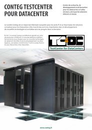
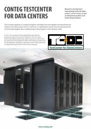
1.8 TestCenter for Data Centers TC4DC<br />
<strong>Conteg</strong>’s TestCenter for Data Center in Pelhřimov, Czech Republic was built especially for testing new and existing products<br />
and their impact in different configurations on the overall power consumption, efficiency, reliability and effectiveness of<br />
data centers. Computer simulations and real measurements in the laboratory allow specialists in the company to verify the<br />
principles of the various processes in the server rooms and to implement innovative solutions. TC4DC is also a gathering<br />
place for experts and training specialists in the design, build-out, and maintenance of data centers. We would like to also<br />
offer our clients the premises and equipment in the experimental data center to test any components, and see how the<br />
components might react to varying critical conditions, which are difficult and far too risky to simulate in the real operation.<br />
Finally, our clients can also use premium wired and wireless measuring instruments for testing and auditing existing data<br />
centers to obtain information about how to optimize and use the advancements in the industry.<br />
4<br />
TestCenter for DataCenters<br />
:: TC4DC<br />
Basic information<br />
Covered area - <strong>Conteg</strong>´s TC4DC testing lab covers a total area of 156 m 2<br />
and consists of two areas - an experimental data center and rooms for<br />
technical support.<br />
Experimental data center – designed as a real data center with<br />
a raised floor and suspended ceiling, the area of the laboratory is 75 m 2<br />
and is separated from a technical workshop and observation area by a glass<br />
wall. The experimental room arrangement can simulate real life situations.<br />
It is possible to install individual racks, their rows, contained aisles and also<br />
closed-loops.<br />
Room for technical equipment – place for hardware and software to<br />
operate the center, a conference room and presentation equipment.<br />
Ancillary spaces - there is a workshop area to place the hardware used<br />
for testing and computers to run software to examine the results, along<br />
with a conference room for team meetings and technical presentations.<br />
Laboratory equipment<br />
• Cooling system - several variable cooling options for testing different<br />
variants of traditional and experimental arrangement of ICT cabinets<br />
with thermal loading are available. There are two, 80 kW water cooled<br />
CRAC units (Computer Room Air Conditioning) installed with air blowing<br />
under the raised floor. Moreover, there are 12 positions for the chilled<br />
water connection for different versions of air conditioning units. By<br />
default, CoolTeg units integrated into the rows of rack are offered with<br />
a cooling capacity of 35 kW. The cooling source is two water-cooled<br />
chillers with an output of 80 kW, one of which is equipped with freecooling<br />
accessories. Thanks to sophisticated control, accumulation tanks,<br />
and control valves, each independent system delivers the necessary<br />
chilled water temperatures and flow rates. At the same time, it is also<br />
possible to accurately measure all energy flows. In addition to the water<br />
cooling system, we can also offer a compressor system with two outdoor<br />
units with a capacity of 20 kW operating with R410A refrigerant.<br />
• Sources of heat – the laboratory is equipped with 20 heat sources, which<br />
can be installed in 19" racks. Each source has a continuous control of<br />
airflow and can regulate heating power in steps of 2 kW for up to 6 kW of<br />
total heating power.<br />
22
Measuring instruments<br />
• A system of sensors for long-term monitoring of quantities in the<br />
laboratory transmits information to a measuring central unit. The data is<br />
then processed and archived by specially designed laboratory software<br />
that allows for the evaluation, visualization, and presentation of data<br />
from individual experiments.<br />
• Independent measuring system is a system for measuring central unit<br />
and wireless temperature and humidity sensors that can be used both<br />
in the laboratory and in a real data center for verification of laboratory<br />
measurements in practice.<br />
• Separate calibrated measuring instruments for accurate verification<br />
of all local variables (sound meter, thermal imagers, anemometers,<br />
thermometers, hygrometers, CO 2<br />
sensor, pressure gauges, wattmeter,<br />
ammeter, oscilloscope, tachometer, etc.)<br />
:: TC4DC<br />
Some examples of what can be measured:<br />
• humidity<br />
• temperature (water, air, and surface of all equipment and racks)<br />
• air flow and water flow<br />
• speed of air flow and water flow<br />
• pressure differences in individual parts of experimental arrangements<br />
• CO 2<br />
concentration<br />
• electrical parameters (voltage, current, power consumption)<br />
• noise parameters<br />
• fan speed<br />
www.conteg.com 23
1.9 AEGIS Data Center Infrastructure Management (DCIM)<br />
<strong>Conteg</strong> has developed the Aegis DCIM system which<br />
collects, analyzes, and reports all the necessary information<br />
using standardized data communication protocols.<br />
Data centers have changed considerably throughout the years;<br />
an evolution of information technology has resulted in data centers<br />
becoming the critical nerve center of today’s enterprise. The efficiency of<br />
data centers has become an important topic in a global discussion among<br />
end-users, policy makers, technology providers, and facility architects.<br />
DCIM has a real-time performance dashboard with metrics like PUE, EUE,<br />
EER, etc. DCIM monitors the status of the data center and reports defects/<br />
equipment malfunctions and temperature problems, like excessive<br />
humidity or temperatue levels. Aegis is not only a conventional DCIM, but<br />
it can also control the strategic equipment of data centers to improve PUE.<br />
One of the important highly developed data center metrics used<br />
to measure overall efficiency is PUE (Power Usage Effectiveness)<br />
developed by The Green Grid. PUE is equal to the total power used by<br />
the facility to support the IT load, for example cooling, UPS, and lighting<br />
divided by the total IT equipment power consumption. In general, PUE<br />
calculations, compared with manually gathered information, takes<br />
place on a monthly basis. Manual calculation is only useful for reporting.<br />
If you want to improve the operation of the data center, then the metrics<br />
should be based on real-time information.<br />
Improving efficiency reduces the operational expenses (OPEX) of your<br />
data center, and helps make the facility compliant with current and<br />
developing governmental regulations, and immediately reduces your<br />
carbon footprint. Data center monitoring and control is a critical element<br />
for maintaining maximum availability of your critical operations. <strong>Conteg</strong><br />
developed the Aegis DCIM system which collects, analyzes and reports<br />
all the necessary information using standardized data communication<br />
protocols. With DCIM, you have full control of your data center.<br />
Aegis DCIM<br />
<strong>Conteg</strong>’s Aegis - Data Center Infrastructure Management (DCIM) is<br />
a complete monitoring application for managing data center infrastructure.<br />
Data center efficiency<br />
<strong>Conteg</strong>’s Aegis (DCIM) system collects, analyzes, reports, and<br />
manages infrastructure equipment in real-time using standardized data<br />
communication protocols. Improving efficiency reduces the operational<br />
expenses (OPEX) of a data center, and will reduce the data center’s carbon<br />
footprint. It also helps to make the facility compliant with current and<br />
future developing governmental regulations.<br />
:: Aegis (DCIM)<br />
Integration to third-party applications<br />
<strong>Conteg</strong>’s Aegis DCIM is designed to operate with all types of<br />
devices, equipment and third-party software applications. Aegis DCIM<br />
supports communication with data bases, including SAP BAPI (Business<br />
Application Programming Interface), MS SQL server 2 008, My SQL,<br />
Oracle, MS Access, ODBC, OLEDB and the data mining tool Grid Control,<br />
which enables OPC, SNMP. AEGIS DCIM is customized based on the<br />
individual needs of each client.<br />
Scalable solutions:<br />
The <strong>Conteg</strong> Aegis Infrastructure Management can be adapted to fit all<br />
scenarios. The solution has been tailored to suit three levels of projects:<br />
a Server Room version for projects of up to 10 cabinets/racks, an Enterprise<br />
Data Center version for projects of up to 32 cabinets/racks and a Global<br />
version that can meet the requirements for a data center project regardless<br />
of size or scale.<br />
Technical information<br />
• Useful computer room information: metrics like PUE, EUE, EER, etc. are<br />
shown on Aegis DCIM dashboard<br />
• Alarm for defects/equipment malfunctions, temperature problems, like<br />
excessive humidity or temperature levels<br />
• Monitoring and reporting of IT equipment’s energy consumption at<br />
facility, row, rack or outlet level<br />
• Monitoring of electrical breaker loads, based on actual and daily peak<br />
load values<br />
• Capacity reports<br />
• Local and remote accessibility via a standard web portal<br />
• Data security on various levels<br />
24
1.10 CFD Modeling<br />
<strong>Conteg</strong> licenses a highly specialized application specifically designed to produce detailed CFD simulations of temperature<br />
distribution and airflow in the data center. The CFD simulation can be based on data you provide via electronic file transfer<br />
with the <strong>Conteg</strong> Technical Team or gathered from on-site surveys conducted at your data center by <strong>Conteg</strong> data center<br />
specialists. Either way, <strong>Conteg</strong>, using the CFD software, will prepare a model which will provide both tabular data along with<br />
a 3D AVI simulation. The data can be used by IT and facility management staff to verify assumptions related to the operation<br />
or design of a data center, reduce OPEX by testing optimization schemes or for planning the most efficient way of adding or<br />
rearranging IT or cooling equipment.<br />
Computer modeling creates a bridge between information related to the operation of the mechanical systems and the varying operation of the IT<br />
equipment heat load so that the IT and facilities staff can optimize the efficacy of air flows and maximize cooling capacity. CFD modeling is a tool that<br />
can be used both in the planning stage of data centers, as well as for the analysis of how design assumptions are functioning in an operating data center.<br />
Globally, for reasons such as good corporate citizenship, regulatory mandates and reductions in available electrical utility capacity, it has become common,<br />
almost essential, that a data center design team verify the functional characteristics of data hall projects. In order to attain effectively cooled high-density<br />
IT equipment configurations, CFD modeling is also being applied to server and telecommunications equipment room designs.<br />
:: CFD modeling<br />
Data centers and server rooms are loaded<br />
with many different types of equipment and<br />
systems. Each of the systems, for example,<br />
a row of SAN equipment, Network Switching<br />
equipment, or high-density servers, results in<br />
a variety of different sources of heat and cold.<br />
How these disparate systems impact the air<br />
and pressures in the room becomes extremely<br />
complicated. Methods of computer modeling,<br />
especially Computational Fluid Dynamics (CFD),<br />
remove the guesswork by analyzing the variants<br />
in detail and graphically display the effects on<br />
the temperature distribution, velocity, and air<br />
pressure in the space.<br />
CFD modeling is not a silver bullet, but pragmatic use of the tool can help in the optimization of designs or in researching how to reduce the OPEX<br />
of an operating facility. The following are some of the advantages which can be realized by implementing a CFD model for a data center or server room<br />
design or an existing operating data center.<br />
• Verification of assumptions related to how the data center or server room cooling system will operate.<br />
• Crisis Management – How does the designed redundancy function should a cooling unit fail<br />
• The company plans to virtualize applications. So what happens if a new bank of high-density servers are added<br />
• Would the data center operate more efficiently if we re-arranged some of the IT equipment<br />
• Would the data center operate more efficiently if we made adjustments to the cooling system<br />
• What happens if we increase the server inlet temperature to the IT equipment<br />
• What happens if we increase the chilled water temperature to the cooling units<br />
When an experienced <strong>Conteg</strong> specialist familiar<br />
with numerous design models collaborates<br />
with your team, your design challenges can be<br />
resolved. Even more importantly, by simulating<br />
crisis scenarios, unknown variables and problems<br />
can be prevented from happening. There is no<br />
need to search for the optimal arrangement of<br />
data center solutions by trial and error, as each<br />
attempt costs time and unnecessary expense.<br />
www.conteg.com 25
2. FREE-STANDING RACKS<br />
2. FREE-STANDING RACKS 26<br />
PREMIUM Rack Series 27<br />
2.1 PREMIUM Heavy RHF 28<br />
2.2 PREMIUM Cabling RDF 32<br />
2.3 PREMIUM Server RSF 36<br />
2.4 PREMIUM Rack Series<br />
Plates<br />
40<br />
2.5 PREMIUM Housing RSB 42<br />
OPTIMAL Rack Series 44<br />
2.6 OPTIMAL ROF 45<br />
2.7 OPTIMAL Flex RMF 50<br />
2.8 Special OPTIMAL 55<br />
OPTIMAL PC ROP<br />
OPTIMAL Twist ROR<br />
OPTIMAL Cable<br />
Management<br />
iSEVEN Rack Series 58<br />
2.9 iSEVEN Ri7 59<br />
2.10 iSEVEN Flex RM7 63<br />
Open frames, Space Optimization<br />
Sections, Extrusions<br />
68<br />
2.11 Open Frames RSG4 68<br />
2.12 Open Frames RSG2 69<br />
2.13 Open Frames RS 70<br />
2.14 Space Optimization 71<br />
Section<br />
2.15 Extrusions 73<br />
:: free-standing racks<br />
26
PREMIUM RACK SERIES<br />
PREMIUM<br />
We have embodied all the traditional requests of users into the PREMIUM rack series design and made it the TOP rack<br />
series in the <strong>Conteg</strong> rack portfolio. With PREMIUM racks, the variability acquires a new dimension – only the frame remains<br />
the same. All other parts – 19” extrusions, top and bottom plates, front and rear doors or panels, locks, side panels, feet<br />
or plinth – can be defined by you. A wide portfolio of all the mentioned parts is ready to be applied, so an individual rack,<br />
meeting the most demanding requirements of data center and server rooms IT administrators, can be defined. Although<br />
the main design features remain the same, three configurations according to specific user needs have been pre‐designed…<br />
PREMIUM HEAVY RHF<br />
The PREMIUM Heavy RHF rack is designed<br />
to cope with the increased loads of today’s IT<br />
equipment within a data center, equipment<br />
room and network or telecommunications<br />
closet. The PREMIUM Heavy RHF’s heavy-duty,<br />
all-welded frame and 1 500 kg load rating mean<br />
that it’s possible to accommodate the heaviest<br />
equipment within a standard rack footprint.<br />
:: premium rack series<br />
Heavy-duty design of 19” vertical extrusion gives<br />
PREMIUM Heavy RHF a 1 500 kg load rating.<br />
PREMIUM CABLING RDF<br />
The PREMIUM Cabling RDF rack is designed as a dedicated cabling cabinet intended to be<br />
used in data centers, equipment rooms and network or telecommunication closets. Moreover,<br />
PREMIUM Cabling RDF is fully compatible with all cooling units from the Targeted Cooling portfolio<br />
and recommended to be used together with CoolSpot A/C units. We have developed special<br />
cabling systems like High Density Wire Management (see page 85), the optical pathway system<br />
OptiWay (see page 89) and Top Ducts (see page 94) hand‐in‐hand with this PREMIUM rack series<br />
configuration. We strongly recommend you combine the PREMIUM Cabling RDF rack series with<br />
both these cabling systems to give your cables the best possible support and care.<br />
PREMIUM SERVER RSF<br />
The PREMIUM Server RSF rack is designed as a dedicated server cabinet and is intended to be<br />
used in data centers, equipment rooms and network or telecommunication closets. The PREMIUM<br />
Server RSF’s heavy-duty, all-welded construction and 1 500 kg load rating mean that it’s possible to<br />
accommodate the heavy equipment within a standard rack footprint. A full range of complementary<br />
systems (see page 114), like Intelligent Power PDUs (see page 124), is ready to be used together with<br />
PREMIUM Server RSF racks to make the housing of your servers even more safe and comfortable.<br />
Interchangeable top<br />
and bottom plates<br />
in various design<br />
options provide<br />
a unique interface<br />
between in‐rack and<br />
out‐of‐rack cabling<br />
systems (illustrative<br />
image only)<br />
RHF’s design will perfectly fit even in a row of cabling<br />
(RDF) or server (RSF) racks<br />
Rear pair of 19”<br />
extrusions is vertically<br />
divided to allow for<br />
various depth settings<br />
to accommodate<br />
different servers.<br />
PREMIUM RACK SERIES PLATES<br />
A unique system of interchangeable<br />
PREMIUM plates consists of 3 different top cover<br />
single‐piece plates and a wide range of bottom<br />
plate options. You can create a unique design for<br />
your bottom plate in a short and easy way. To find<br />
out more information on PREMIUM plates, go to<br />
page 40.<br />
www.conteg.com 27
2.1 PREMIUM Heavy RHF<br />
The PREMIUM Heavy RHF rack is designed to cope with the increased loads of today’s IT equipment within a data center,<br />
equipment room and network or telecommunications closet. The RHF’s heavy-duty, all-welded frame and 1 500 kg load<br />
rating mean that it’s possible to accommodate the heaviest equipment within a standard rack footprint. The RHF comes<br />
with a full range of doors, panels and locks. This racks is 42U tall with a depth of 1 000 mm and widths of 600 mm and<br />
800 mm. The RHF is designed to work with <strong>Conteg</strong>’s air‐flow optimization solutions and flexible cable management system<br />
(see page 85 to find out more on High Density Wire Managers), which means that the RHF can be tailored to suit your needs.<br />
PREMIUM<br />
RHF‐42‐80/100<br />
DESCRIPTION:<br />
Sizes<br />
• Height: 42U<br />
• Width: 600, 800 mm<br />
• Depth: 1 000 mm<br />
Construction<br />
• Welded-frame design<br />
• 2.5 mm sheet steel<br />
COLOR SAMPLER:<br />
Load rating<br />
• 1500 kg balanced load<br />
19" vertical extrusions<br />
• 2 pairs of sliding 19"vertical L-type (600 mm)<br />
or P-type (800 mm) extrusions (provides<br />
additional 12U of installation space);<br />
adjustable from inside<br />
• C-type extrusions option (800 mm)<br />
IP rating<br />
• Standard IP20<br />
• IP40 when solid doors or panels applied<br />
• Optionally up to IP54 with multipoint lock<br />
only<br />
• A/C ready – IP54 when A/C unit installed with<br />
multipoint lock only<br />
Colors<br />
• Standard RAL 7035 and 9005<br />
• Other color options<br />
Front door<br />
• Vented door – perforation rate 83%<br />
• Swivel handle lock – DIN profile, universal<br />
key 333, multipoint; half-profile cylinder<br />
or combination lock single or multi-point<br />
options (other locks on request)<br />
• Door opening angle 180°<br />
• Easy re‐hanging to open on right or left<br />
• Optionally glass, steel, perforated, glass with<br />
perforation, vertically divided door<br />
RAL 9005<br />
RAL 7035<br />
Rear door<br />
• Vented door – perforation rate 83%<br />
• Swivel handle lock – DIN profile, universal<br />
key 333, multipoint; optionally half profile<br />
cylinder or combination lock single or multipoint<br />
(other locks on request)<br />
• Optionally can be replaced by full range of<br />
front doors and panels<br />
Side panels<br />
• Removable with locks<br />
Top plate<br />
• Single‐piece design, removable<br />
• 4" (100 mm) rounded cable entry in every<br />
corner covered by plastic cap<br />
• 300×100 mm cable entries covered with<br />
removable sheet steel blank panels<br />
Bottom plate<br />
• Segmented design, removable<br />
• 4" (100 mm) rounded cable entry in every<br />
corner covered by plastic caps<br />
• 300×100 mm cable entries covered with<br />
removable sheets steel blank panels<br />
Feet<br />
• Adjustable feet as standard; high-load plinth<br />
option<br />
Adaptation<br />
• Possibility to adapt for installation of 21"<br />
equipment (on request) - valid for 800 mm<br />
width<br />
• Adaptor DP‐RE‐01 (ordered separately)<br />
Other<br />
• Racks can be installed in blocks by using<br />
DP‐DR‐UNI (ordered separately)<br />
• CoolTeg and CoolSpot cooling units<br />
compatible – see page 101 for details<br />
• GND/earthing kit included<br />
:: premium heavy RHF<br />
28
HIGHLY RECOMMENDED EQUIPMENT<br />
13 14 15 16 17 18 19 1 20 21<br />
:: premium heavy RHF<br />
12<br />
22 23 24<br />
4<br />
29<br />
27<br />
25<br />
2<br />
6<br />
26<br />
27<br />
10<br />
11<br />
5<br />
30<br />
9<br />
7<br />
3<br />
8<br />
9<br />
28<br />
This is example of 19" RHF<br />
800 rack, for other types<br />
and options see page 31<br />
"ordering matrix".<br />
STANDARD EQUIPMENT<br />
1 Front and rear vented door 83% with multipoint swivel handle lock<br />
2 2 pairs of 19" sliding extrusions with U marking<br />
3 Holders for vertical extrusions<br />
4 1 pair of side panels with lock<br />
5 Adjustable feet<br />
6 Frame of rack<br />
7 Removable F‐design top plate with cable entry openings<br />
8<br />
Removable segmented bottom plate set (consists of C and F-design<br />
plates, may differ for other rack footprints) with cable entry openings<br />
9 Plastic caps and blank panels for cable entry openings<br />
‐ GND/earthing kit<br />
‐ 28 mounting kits<br />
‐ BONUS: 2 rounded cable grommets with brush DP‐KP‐RB4 for free<br />
OPTIONAL EQUIPMENT (EXAMPLES)<br />
10 Plinth<br />
11 Plinth with filter<br />
12 1 pair of side panels with perforation<br />
13 Vertically divided glass door 1,2<br />
14 Vertically divided glass door with perforation 1,2<br />
15 Vertically divided vented door 83% 2<br />
16 Vertically divided perforated sheet steel door 2<br />
17 Vertically divided sheet steel door 2<br />
18 Glass door<br />
19 Glass door with side perforation<br />
20 Perforated sheet steel door<br />
21 Sheet steel door<br />
22 Rear panel with module<br />
23 Rear panel – 1 piece<br />
24 Rear panel – perforated<br />
25 Removable B‐design top plate with cable entry and ventilation openings<br />
26<br />
Removable B‐design top plate (used for bottom) with cable entry and<br />
ventilation openings<br />
27 Rounded cable grommet with brush<br />
28 Blank panels for ventilation openings<br />
29 Ventilation unit<br />
30 Connecting kit with filter for ventilation unit<br />
1<br />
not available for 600 mm wide racks<br />
2<br />
requires multipoint lock<br />
www.conteg.com 29
Bottom view<br />
Rear view<br />
Side view<br />
Front view<br />
height<br />
800 depth<br />
Top view<br />
Bottom view<br />
Rear view<br />
Side view<br />
Front view<br />
Cable entries – racks 800×1 000 mm<br />
• 5 openings (300×100 mm) in both top and<br />
bottom plates<br />
• 4 openings 4"(100 mm) in both top and<br />
bottom plates<br />
height<br />
Cable entries – racks 600×1 000 mm<br />
• 2 openings (300×100 mm) in both top and<br />
bottom plates<br />
• 4 openings 4" (100 mm) in both top and<br />
bottom, plates<br />
All cable entries are covered by blanking panels<br />
or plastic caps.<br />
An individual plates can be defined<br />
‐ go to page 40.<br />
600<br />
depth<br />
Top view<br />
:: premium heavy RHF<br />
Code<br />
H in U<br />
Load rating<br />
in kg<br />
* Height in mm without feet; for feet add 16‐45 mm<br />
Dimensions in mm Dimensions including packing in mm Gross weight<br />
in kg<br />
H* W D Useful depth H W D<br />
RHF‐42‐60/100 42 1500 1978 600 1000 990 2160 640 1040 143<br />
RHF‐42‐80/100 42 1500 1978 800 1000 990 2160 840 1040 171<br />
Note: All dimensions in mm<br />
30
R<br />
H<br />
F<br />
‐<br />
1.<br />
‐<br />
2.<br />
ORDERING AND SHIPPING INFORMATION: Configure the rack that will meet your requirements. The ordering matrix below<br />
will help you to create the part number. As soon as you have the part number, please contact your <strong>Conteg</strong> products distributor.<br />
Please note that all RHF RACKS ARE DELIVERED FULLY ASSEMBLED and palletized!<br />
FOLLOW THE STEPS TO SET UP THE DESIRED RHF RACK PRODUCT CODE!<br />
1<br />
2<br />
3<br />
HEIGHT<br />
Code<br />
Height<br />
in U<br />
External<br />
height<br />
in mm<br />
42 42 1 978<br />
WIDTH<br />
Code<br />
Width in mm<br />
60 600<br />
80 800<br />
DEPTH<br />
Code<br />
Depth<br />
in mm<br />
Useful<br />
depth<br />
in mm<br />
10 1 000 990<br />
4<br />
11<br />
EXTRUSIONS<br />
Code Front pair Rear pair Note<br />
0 L L L-type undivided extrusions – for racks 600 mm wide only<br />
P P P<br />
P-type undivided extrusions – for racks 800 mm wide only, each extrusion with 3<br />
additional 19" vertical positions, blank panels not included<br />
C C C<br />
C-type undivided extrusions with rounded cable troughs covered with plastic<br />
caps – for racks 800 mm wide only<br />
PLATES 1<br />
Code Top plate Bottom plate Note<br />
A B Z Top and bottom single piece plates, required for IP54<br />
C no top Z Open top – for A/C-ready option (table 10)<br />
E F XXX 2 Standard – one piece top plate, segmented bottom plate<br />
F F no bottom 3 Open bottom – ready for installation on raised floor or plinth<br />
X no top 3 no bottom 3 Open top and bottom, for individual plates go to page 40<br />
1 For more information on plates go to page 40<br />
2<br />
600×1000: BHB, 800×1000: CHC<br />
3<br />
Open top or bottom results in no IP protection unless otherwise stated<br />
:: premium heavy RHF<br />
/<br />
3.<br />
4.<br />
‐<br />
5.<br />
6.<br />
7.<br />
8.<br />
9.<br />
‐<br />
10.<br />
11.<br />
12.<br />
‐<br />
13.<br />
5<br />
12<br />
FRONT DOOR<br />
Code Note<br />
0 Without door 1<br />
G Glass door<br />
S Sheet steel door<br />
P Perforated sheet steel door 2<br />
T Glass door with side perforation 3<br />
W Vented door (perforation rate 83%) 5<br />
A Vertically divided glass door 4 *<br />
B Vertically divided glass door with side perforation 6 *<br />
C Vertically divided sheet steel door 4<br />
D Vertically divided perforated sheet steel door 5<br />
F Vertically divided vented door (perforation rate 83%) 5<br />
Other<br />
1<br />
no IP protection<br />
2<br />
IP20 max.<br />
3<br />
IP30 max.<br />
4<br />
multipoint lock only<br />
6<br />
10<br />
LOAD RATING<br />
Code<br />
Load rate<br />
in kg<br />
Note<br />
F 1500<br />
Balanced<br />
load<br />
5<br />
multipoint lock only, IP20 max.<br />
6<br />
multipoint lock only, IP30 max.<br />
*<br />
these options apply to RHF 800 only<br />
FRONT DOOR LOCK<br />
Code Options<br />
1 Swivel handle with electronic lock, universal key<br />
3 Swivel handle with electronic lock, universal key, multipoint<br />
E Swivel handle with combination lock and universal key<br />
F Swivel handle with combination lock and universal key, multipoint<br />
G Swivel handle with combination lock, keyed different<br />
H Swivel handle with combination lock, keyed different, multipoint<br />
I Swivel handle with profile half cylinder, universal key<br />
J Swivel handle with profile half cylinder, universal key, multipoint<br />
K Swivel handle with profile half cylinder, keyed different<br />
L Swivel handle with profile half cylinder, keyed different, multipoint<br />
V Swivel handle DIN profile, universal key, 333<br />
W Swivel handle DIN profile, universal key, 333, multipoint<br />
Other<br />
13<br />
COLOR<br />
Code<br />
B<br />
H<br />
Note<br />
RAL 7035 (light gray)<br />
RAL 9005 (black)<br />
IP RATING 1<br />
Code Note<br />
1<br />
According to EN 60529<br />
A A/C ready 2<br />
0 IP00<br />
2<br />
Ready for AC unit installation;<br />
2 IP20<br />
recommended when cooling is planned<br />
3 IP30<br />
or required; IP54 when AC unit installed<br />
according to instructions<br />
4 IP40<br />
3<br />
Multipoint lock only<br />
5 IP54 3<br />
An example of a correct product code<br />
RHF‐42‐80/10P‐SWCWA‐5AF‐B<br />
REAR DOOR / PANEL<br />
Code Note<br />
0 Without panel/door 1<br />
G Glass door<br />
S Sheet steel door<br />
P Perforated sheet steel door 2<br />
T Glass door with side perforation 3<br />
W Vented door (perforation rate 83%) 5<br />
7 A Vertically divided glass door 4 *<br />
B Vertically divided glass door with side perforation 6 *<br />
C Vertically divided sheet steel door 4<br />
D Vertically divided perforated sheet steel door 5<br />
F Vertically divided vented door (perforation rate 83%) 5<br />
Y Rear panel – single piece 7<br />
R Rear panel – divided, with cable entry 7<br />
Z Perforated rear panel – single piece 8<br />
Other<br />
1<br />
no IP protection<br />
6<br />
multipoint lock only, IP30 max.<br />
2<br />
IP20 max.<br />
3<br />
IP30 max.<br />
4<br />
multipoint lock only<br />
5<br />
multipoint lock only, IP20 max.<br />
8<br />
9<br />
7<br />
Lock code U or X only<br />
8<br />
Lock code U or X only, IP20 max.<br />
*<br />
these options apply to RHF 800 only<br />
REAR DOOR / PANEL LOCK<br />
Code Options<br />
1 Swivel handle with electronic lock, universal key<br />
3 Swivel handle with electronic lock, universal key, multipoint<br />
E Swivel handle with combination lock and universal key<br />
F Swivel handle with combination lock and universal key, multipoint<br />
G Swivel handle with combination lock, keyed different<br />
H Swivel handle with combination lock, keyed different, multipoint<br />
I Swivel handle with profile half cylinder, universal key<br />
J Swivel handle with profile half cylinder, universal key, multipoint<br />
K Swivel handle with profile half cylinder, keyed different<br />
L Swivel handle with profile half cylinder, keyed different, multipoint<br />
V Swivel handle DIN profile, universal key, 333<br />
W Swivel handle DIN profile, universal key, 333, multipoint<br />
U Lock for rear panel, universal key<br />
X Lock for rear panel, keyed different<br />
Other<br />
SIDE PANELS (BOTH SIDES) *<br />
Code Note<br />
0 No side panels<br />
A 2 side panels, sheet steel, universal key<br />
B 1 side panel, sheet steel, universal key<br />
C 2 side panels, sheet steel, individual key<br />
D 1 side panel, sheet steel, individual key<br />
E 2 side panels, sheet steel with perforation, universal key<br />
F 1 side panel, sheet steel with perforation, universal key<br />
G 2 side panels, sheet steel with perforation, individual key<br />
H 1 side panel, sheet steel with perforation, individual key<br />
Other<br />
* open side / sides results in no IP protection; side panels with perforation result in<br />
protection rating IP20 max.<br />
www.conteg.com 31
2.2 PREMIUM Cabling RDF<br />
The PREMIUM Cabling RDF rack is designed as a cabling cabinet for data centers, equipment rooms and network or<br />
telecommunication closets. Moreover, RDF is fully compatible with all cooling units from the Targeted Cooling portfolio and<br />
is already preconfigured to be used with CoolSpot A/C units. RDF’s flexible configuration options allow you to easily tailor the<br />
design to meet your exact requirements for quantity, position and type of cable entry openings. RDF comes with a full range of<br />
doors, panels and locks and is designed to work with <strong>Conteg</strong>’s airflow optimization solutions. Advanced cabling systems, like<br />
High Density Wire Management, OptiWay and Top Ducts (see page 94), are ready to complete RDF’s installation and provide<br />
any type of cabling with the best possible support and care.<br />
COLOR SAMPLER:<br />
RAL 9005<br />
RAL 7035<br />
DESCRIPTION:<br />
PREMIUM<br />
RDF‐42‐80/80<br />
Sizes<br />
• Height: 27, 42, 45, 48U<br />
• Width: 800 mm<br />
• Depth: 800, 1 000, 1 200 mm (1 200 mm not<br />
available for 27U)<br />
Construction<br />
• Welded-frame design<br />
• 1.5 & 2.0 mm sheet steel<br />
Load rating<br />
• 500 kg balanced load (for 27U 300 kg only)<br />
19" vertical extrusions<br />
• 2 pairs of sliding 19" extrusions, adjustable<br />
from inside<br />
• C-type extrusion option<br />
IP rating<br />
• Standard IP40<br />
• Optionally IP54 with multipoint lock only<br />
• IP20 when perforated or vented doors used<br />
• A/C ready – IP54 when A/C unit installed with<br />
multipoint lock only<br />
Colors<br />
• Standard RAL 7035 and 9005<br />
• Optionally other colors<br />
Front door<br />
• Tinted security glass door<br />
• Swivel handle lock – DIN profile, universal<br />
key 333, multipoint; half-profile cylinder<br />
or combination lock single or multi-point<br />
options (other locks on request)<br />
• Door opening angle 180°<br />
• Easy re‐hanging to open on right or left<br />
• Optionally steel, vented, perforated, glass<br />
with perforation, vertically divided door<br />
Rear door<br />
• Sheet steel door<br />
• Swivel handle lock – DIN profile, universal<br />
key 333, multipoint; optionally half profile<br />
cylinder or combination lock single or<br />
multipoint (other locks on request)<br />
• Can be replaced by a full range of gront door<br />
and panel options<br />
Side panels<br />
• Removable with locks<br />
Top plate<br />
• Single‐piece design, removable<br />
• 4" (100 mm) rounded cable entry in every<br />
corner covered by plastic cap<br />
• 300×100 mm cable entries covered with<br />
removable sheet steel blank panels<br />
• 300×50 mm cable entries covered with<br />
removable sheet steel blank panels<br />
• 420×280 mm ventilation opening(s) covered<br />
with removable sheet steel blank panel, allow<br />
for installation of 6‐fan ventilation unit(s)<br />
(800 mm and 1200 mm deep racks only)<br />
• 420×440 mm ventilation opening covered<br />
with removable sheet steel blank panel,<br />
allow for installation of 9‐fan ventilation unit<br />
(1000 mm deep racks only)<br />
Bottom plate<br />
• Segmented design, removable<br />
• 4" (100 mm) rounded cable entry in every<br />
corner covered by plastic caps<br />
• 300×100 mm cable entries covered with<br />
removable sheets steel blank panels<br />
Feet<br />
• Adjustable feet as standard; castors, lockable<br />
castors, plinth or plinth with filter options<br />
Adaptation<br />
• Possibility to adapt for installation of 21"<br />
equipment<br />
• Adaptor DP‐RE‐01 needed (ordered separately)<br />
Other<br />
• Racks can be installed in blocks by using<br />
DP‐DR‐UNI (ordered separately)<br />
• CoolTeg and CoolSpot cooling units<br />
compatible – see page 101 for details<br />
• GND/earthing kit included<br />
:: premium cabling RDF<br />
32
HIGHLY RECOMMENDED EQUIPMENT<br />
15 16 17 18 19 1 20 21 22 2<br />
5<br />
14<br />
:: premium cabling RDF<br />
23 24 25<br />
30<br />
28<br />
11<br />
26<br />
8<br />
3<br />
7<br />
9<br />
27<br />
10<br />
12<br />
13<br />
6<br />
29<br />
10<br />
4<br />
28<br />
STANDARD EQUIPMENT<br />
1 Front glass door with swivel handle lock<br />
2 Rear sheet steel door with swivel handle lock<br />
3 2 pairs of 19" sliding extrusions<br />
4 Holders for vertical extrusions<br />
5 1 pair of side panels with lock<br />
6 Adjustable feet<br />
7 Frame of rack<br />
8 Removable I‐design top plate with cable entry and ventilation openings<br />
9<br />
Removable segmented bottom plate set (consists of C and F-design plates<br />
and may differ for other rack footprints) with cable entry openings<br />
10 Plastic caps and blank panels for cable entry openings<br />
11 Blank panel for ventilation opening<br />
‐ GND/earthing kit<br />
‐ 28 mounting kits<br />
‐ BONUS: 2 rounded cable grommets with brush DP‐KP‐RB4 for free<br />
OPTIONAL EQUIPMENT (EXAMPLES)<br />
12 Plinth<br />
13 Plinth with filter<br />
14 1 pair of side panels with perforation<br />
15 Vertically divided glass door *<br />
16 Vertically divided glass door with perforation *<br />
17 Vertically divided vented door 83% *<br />
18 Vertically divided perforated sheet steel door *<br />
19 Vertically divided sheet steel door *<br />
20 Glass door with side perforation<br />
21 Vented door 83% *<br />
22 Perforated sheet steel door<br />
23 Rear panel with module<br />
24 Rear panel – 1 piece<br />
25 Rear panel – perforated<br />
26 Removable B‐design top plate with cable entry and ventilation openings<br />
Removable segmented bottom plate set (consists of B and G-design plates<br />
27 and may differ for other rack footprints) with cable entry and ventilation<br />
openings<br />
28 Rounded cable grommet with brush<br />
29 Ventilation unit<br />
30 Connecting kit with filter for ventilation unit<br />
* requires multipoint lock<br />
www.conteg.com 33
Bottom view<br />
Top plates – I design<br />
800×800<br />
Rear view<br />
Side view<br />
Front view<br />
800×1 200<br />
800×1 000<br />
height<br />
800<br />
depth<br />
Top view<br />
Cable entries and ventilation openings – racks 800×800 mm<br />
• 2 openings 300×100 mm in top plate<br />
• 2 openings 300×50 mm in top plate<br />
• 5 openings 300×100 mm in bottom plate<br />
• 4 openings 4" (100 mm) in both top and bottom plates<br />
• 1 ventilation opening 420×280 mm in top plate<br />
Bottom plates<br />
CFC – 800×800 CHC – 800×1 000 CFFC – 800×1 200<br />
Cable entries and ventilation openings – racks 800×1 000 mm<br />
• 2 openings 300×100 mm in top plate<br />
• 2 openings 300×50 mm in top plate<br />
• 5 openings 300×100 mm in bottom plate<br />
• 4 openings 4" (100 mm) in both top and bottom plates<br />
• 1 ventilation opening 420×440 mm in top plate<br />
Cable entries and ventilation openings – racks 800×1 200 mm<br />
• 2 openings 300×100 mm in top plate<br />
• 4 openings 300×50 mm in top plate<br />
• 8 openings 300×100 mm in bottom plate<br />
• 4 openings 4" (100 mm) in both top and bottom plates<br />
• 2 ventilation openings 420×280 mm in top plate<br />
All cable entries and ventilation unit openings are covered by blanking<br />
panels or plastic caps.<br />
An individual plates can be defined – go to page 40.<br />
:: premium cabling RDF<br />
Code<br />
H in U<br />
Load rating<br />
in kg<br />
Dimensions in mm<br />
H * W D<br />
Dimensions incl. packing in mm<br />
Gross<br />
weight in kg<br />
RDF‐27‐80/80 27 300 1311 800 800 790 1500 840 840 100<br />
RDF‐42‐80/80 42 500 1978 800 800 790 2160 840 840 134<br />
RDF‐45‐80/80 45 500 2111 800 800 790 2290 840 840 141<br />
RDF‐48‐80/80 48 500 2245 800 800 790 2430 840 840 147<br />
RDF‐27‐80/100 27 300 1311 800 1000 990 1500 840 1040 124<br />
RDF‐42‐80/100 42 500 1978 800 1000 990 2160 840 1040 157<br />
RDF‐45‐80/100 45 500 2111 800 1000 990 2290 840 1040 165<br />
RDF‐48‐80/100 48 500 2245 800 1000 990 2430 840 1040 173<br />
RDF‐42‐80/120 42 500 1978 800 1200 1190 2160 840 1240 175<br />
RDF‐45‐80/120 45 500 2111 800 1200 1190 2290 840 1240 198<br />
RDF‐48‐80/120 48 500 2245 800 1200 1190 2430 840 1240 208<br />
* Height in mm without feet; for feet add 16‐45 mm<br />
Note: All dimensions in mm<br />
Useful<br />
depth<br />
H W D<br />
34
R<br />
D<br />
F<br />
‐<br />
1.<br />
‐<br />
2.<br />
ORDERING AND SHIPPING INFORMATION: Configure the rack that will meet your requirements. The ordering matrix below<br />
will help you to create the part number. As soon as you have the part number, please contact your <strong>Conteg</strong> products distributor.<br />
Please note that all RDF RACKS ARE DELIVERED FULLY ASSEMBLED and palletized!<br />
FOLLOW THE STEPS TO SET UP THE DESIRED RDF RACK PRODUCT CODE!<br />
1<br />
2<br />
3<br />
HEIGHT<br />
Code<br />
Height<br />
in U<br />
External<br />
height<br />
in mm<br />
27 27 1311<br />
42 42 1978<br />
45 45 2111<br />
48 48 2245<br />
WIDTH<br />
Code<br />
Width in mm<br />
80 800<br />
DEPTH<br />
Code<br />
Depth<br />
in mm<br />
Useful<br />
depth<br />
in mm<br />
8 800 790<br />
10 1000 990<br />
12 1200 1190<br />
4<br />
11<br />
EXTRUSIONS<br />
Code Front pair Rear pair Note<br />
0 L L L-type undivided extrusions<br />
C C C<br />
C-type undivided extrusions with rounded cable troughs covered with plastic<br />
caps – to be used together with separation frame (800 mm)<br />
PLATES 1<br />
Code Top plate Bottom plate Note<br />
A B Z Top and bottom single piece plates, required for IP54<br />
C no top Z Open top – for A/C-ready option (table 10)<br />
H I XXX/XXXX 2 Standard – one piece top plate, segmented bottom plate<br />
I I no bottom 3 Open bottom – ready for installation on raised floor or plinth<br />
X no top 3 no bottom 3 Open top and bottom, for individual plates go to page 40<br />
1 For more information on plates go to page 40<br />
2<br />
800×800: CFC, 800×1000: CHC, 800×1200: CFFC<br />
3<br />
Open top or bottom results in no IP protection unless otherwise stated<br />
:: premium cabling RDF<br />
/<br />
3.<br />
4.<br />
‐<br />
5.<br />
6.<br />
7.<br />
8.<br />
9.<br />
‐<br />
10.<br />
11.<br />
12.<br />
‐<br />
13.<br />
5<br />
12<br />
FRONT DOOR<br />
Code Note<br />
0 Without door 1<br />
G Glass door<br />
S Sheet steel door<br />
P Perforated sheet steel door 2<br />
T Glass door with side perforation 3<br />
W Vented door (perforation rate 83%) 5<br />
A Vertically divided glass door 4<br />
B Vertically divided glass door with side perforation 6<br />
C Vertically divided sheet steel door 4<br />
D Vertically divided perforated sheet steel door 5<br />
F Vertically divided vented door (perforation rate 83%) 5<br />
Other<br />
1<br />
no IP protection<br />
2<br />
IP20 max.<br />
3<br />
IP30 max.<br />
6<br />
10<br />
LOAD RATING<br />
Code<br />
Load rate<br />
in kg<br />
Note<br />
3 300 27U only<br />
5 500<br />
Balanced<br />
load<br />
4<br />
multipoint lock only<br />
5<br />
multipoint lock only, IP20 max.<br />
6<br />
multipoint lock only, IP30 max.<br />
FRONT DOOR LOCK<br />
Code Options<br />
1 Swivel handle with electronic lock, universal key<br />
3 Swivel handle with electronic lock, universal key, multipoint<br />
E Swivel handle with combination lock and universal key<br />
F Swivel handle with combination lock and universal key, multipoint<br />
G Swivel handle with combination lock, keyed different<br />
H Swivel handle with combination lock, keyed different, multipoint<br />
I Swivel handle with profile half cylinder, universal key<br />
J Swivel handle with profile half cylinder, universal key, multipoint<br />
K Swivel handle with profile half cylinder, keyed different<br />
L Swivel handle with profile half cylinder, keyed different, multipoint<br />
V Swivel handle DIN profile, universal key, 333<br />
W Swivel handle DIN profile, universal key, 333, multipoint<br />
Other<br />
IP RATING 1<br />
Code Note<br />
0 IP00<br />
2 IP20<br />
3 IP30<br />
4 IP40<br />
5 IP54 3<br />
A A/C ready 2<br />
13<br />
COLOR<br />
Code<br />
B<br />
H<br />
Note<br />
RAL 7035 (light gray)<br />
RAL 9005 (black)<br />
1<br />
According to EN 60 529<br />
2<br />
Ready for A/C unit installation;<br />
recommended when cooling is planned<br />
or required; IP54 when A/C unit installed<br />
according to instructions<br />
3<br />
Multipoint lock only<br />
An example of a correct product code<br />
RDF‐45‐80/80‐AWSWA‐AC5‐H<br />
7<br />
9<br />
REAR DOOR / PANEL<br />
Code Note<br />
0 Without panel/door 1<br />
G Glass door<br />
S Sheet steel door<br />
P Perforated sheet steel door 2<br />
T Glass door with side perforation 3<br />
W Vented door (perforation rate 83%) 5<br />
A Vertically divided glass door 4<br />
B Vertically divided glass door with side perforation 6<br />
C Vertically divided sheet steel door 4<br />
D Vertically divided perforated sheet steel door 5<br />
F Vertically divided vented door (perforation rate 83%) 5<br />
Y Rear panel – single piece 7<br />
R Rear panel – divided, with cable entry 7<br />
Z Perforated rear panel – single piece 8<br />
Other<br />
1<br />
no IP protection<br />
2<br />
IP20 max.<br />
3<br />
IP30 max.<br />
4<br />
multipoint lock only<br />
8<br />
5<br />
multipoint lock only, IP20 max.<br />
6<br />
multipoint lock only, IP30 max.<br />
7<br />
Lock code U or X only<br />
8<br />
Lock code U or X only, IP20 max.<br />
REAR DOOR / PANEL LOCK<br />
Code Options<br />
1 Swivel handle with electronic lock, universal key<br />
3 Swivel handle with electronic lock, universal key, multipoint<br />
E Swivel handle with combination lock and universal key<br />
F Swivel handle with combination lock and universal key, multipoint<br />
G Swivel handle with combination lock, keyed different<br />
H Swivel handle with combination lock, keyed different, multipoint<br />
I Swivel handle with profile half cylinder, universal key<br />
J Swivel handle with profile half cylinder, universal key, multipoint<br />
K Swivel handle with profile half cylinder, keyed different<br />
L Swivel handle with profile half cylinder, keyed different, multipoint<br />
V Swivel handle DIN profile, universal key, 333<br />
W Swivel handle DIN profile, universal key, 333, multipoint<br />
U Lock for rear panel, universal key<br />
X Lock for rear panel, keyed different<br />
Other<br />
SIDE PANELS (BOTH SIDES) *<br />
Code Note<br />
0 No side panels<br />
A 2 side panels, sheet steel, universal key<br />
B 1 side panel, sheet steel, universal key<br />
C 2 side panels, sheet steel, individual key<br />
D 1 side panel, sheet steel, individual key<br />
E 2 side panels, sheet steel with perforation, universal key<br />
F 1 side panel, sheet steel with perforation, universal key<br />
G 2 side panels, sheet steel with perforation, individual key<br />
H 1 side panel, sheet steel with perforation, individual key<br />
Other<br />
* open side / sides results in no IP protection; side panels with perforation result in<br />
protection rating IP20 max.<br />
www.conteg.com 35
2.3 PREMIUM Server RSF<br />
The PREMIUM Server RSF rack is designed as a pure server cabinet for data centers, equipment rooms and network<br />
or telecommunication closets. RSF’s heavy-duty, all-welded design and 1 500 kg load rating mean that it’s possible to<br />
accommodate the heavy equipment within a standard rack footprint. The RSF comes with a full range of doors, panels and<br />
locks. Available in various heights and depths, RSF is designed to work with <strong>Conteg</strong>’s airflow optimization solutions and<br />
flexible cable management systems, which means that RSF can be tailored to suit your needs. RSF can be used with many<br />
complementary systems (e.g. Intelligent Power PDUs – see page 124), making your servers safe and secure.<br />
PREMIUM<br />
RSF‐42‐80/80<br />
DESCRIPTION:<br />
Sizes<br />
• Height: 27, 42, 45, 48U<br />
• Width: 600, 800 mm<br />
• Depth: 800, 1 000, 1 200 mm (1 200 mm not<br />
available for 27U)<br />
Construction<br />
• Welded-frame design<br />
• 1.5 & 2.0 mm sheet steel<br />
COLOR SAMPLER:<br />
Load rating<br />
• 1 500 kg balanced load (1 000 kg for 27U only)<br />
19" vertical extrusions<br />
• 2 pairs of sliding 19" vertical L‐type (600 mm)<br />
or P‐type (800 mm) extrusions (Provide<br />
additional 12U of installation space – valid for<br />
racks 42U and taller), adjustable from inside<br />
• Rear pair of vertical extrusions is divided in<br />
up to 3 parts (according to rack’s height) for<br />
individual settings according to server depth<br />
IP rating<br />
• Standard IP20<br />
• IP40 when solid doors or panels applied<br />
• Optionally up to IP54 with multipoint lock<br />
only<br />
• A/C-ready – IP54 when A/C unit installed with<br />
multipoint lock only<br />
Colors<br />
• Standard RAL 7035 and 9005<br />
• Optionally other colors<br />
Front door<br />
• Vented door – perforation rate 83%<br />
• Swivel handle lock – DIN profile, universal<br />
key 333, multipoint; optionally half profile<br />
cylinder or combination lock single or<br />
multipoint (other locks on request)<br />
• Door opening angle 180°<br />
• Easy re‐hanging to open on right or left<br />
• Optionally glass, steel, perforated, glass with<br />
perforation, vertically divided door<br />
RAL 9005<br />
RAL 7035<br />
Rear door<br />
• Vented door – perforation rate 83%<br />
• Swivel handle lock – DIN profile, universal<br />
key 333, multipoint; optionally half profile<br />
cylinder or combination lock single or<br />
multipoint (other locks on request)<br />
• Optionally can be replaced by full range<br />
of front doors and panels<br />
Side panels<br />
• Removable with locks<br />
Top plate<br />
• Single‐piece design, removable<br />
• 4" (100 mm) rounded cable entry in every<br />
corner covered by plastic cap<br />
• 300×100 mm cable entries covered with<br />
removable sheet steel blank panels<br />
Bottom plate<br />
• Segmented design, removable<br />
• 4" (100 mm) rounded cable entry in every<br />
corner covered by plastic caps<br />
• 300×100 mm cable entries covered with<br />
removable sheets steel blank panels<br />
Feet<br />
• Adjustable feet as standard; plinth or plinth<br />
with filter options<br />
Adaptation<br />
• Possibility to adapt for installation of 21"<br />
equipment (on request only for 800 mm<br />
width)<br />
• Adaptor DP‐RE‐01 needed (ordered separately)<br />
Other<br />
• Racks can be installed in blocks by using<br />
DP‐DR‐UNI (ordered separately)<br />
• CoolTeg and CoolSpot cooling units<br />
compatible – see page 101 for details<br />
• GND/earthing kit included<br />
:: premium server RSF<br />
36
HIGHLY RECOMMENDED EQUIPMENT<br />
13 14 15 16 17 18 19 1 20 21<br />
12<br />
4<br />
12<br />
4<br />
29<br />
27<br />
25<br />
:: premium server RSF<br />
30<br />
9<br />
7<br />
22 23 24<br />
22 23 24<br />
29<br />
27<br />
25<br />
2<br />
12<br />
4<br />
30<br />
9<br />
7<br />
3<br />
STANDARD EQUIPMENT<br />
2<br />
1 Front and rear vented door 83% with multipoint swivel handle lock<br />
2 2 pairs of 19" sliding extrusions<br />
3 Holders for vertical extrusions<br />
4 1 pair of side panels with lock<br />
5 Adjustable feet<br />
6 Frame of rack<br />
7 Removable F‐design top plate with cable entry openings<br />
6<br />
Removable segmented bottom plate set (consists of C and F-design<br />
8<br />
plates, may differ for other rack footprints) with cable entry openings<br />
9 Plastic caps and blank panels for cable entry openings<br />
‐ GND/earthing kit<br />
‐ 28 mounting kits<br />
‐ BONUS: 2 rounded cable grommets with brush DP‐KP‐RB4 for free<br />
26<br />
OPTIONAL EQUIPMENT (EXAMPLES)<br />
10 Plinth<br />
27<br />
11 Plinth with filter<br />
12 1 pair of side panels with perforation<br />
9<br />
13 Vertically divided glass door 1,2<br />
3<br />
8<br />
28<br />
14 Vertically divided glass door with perforation 1,2<br />
10<br />
15 Vertically divided vented door 83% 2<br />
6<br />
26<br />
27<br />
9<br />
10<br />
11<br />
5<br />
8<br />
28<br />
22 23 24<br />
16 Vertically divided perforated sheet steel door 2<br />
11<br />
17 Vertically divided sheet steel door 2<br />
18 Glass door<br />
5<br />
19 Glass door with side perforation<br />
20 Perforated sheet steel door<br />
21 Sheet steel door<br />
22 Rear panel with module<br />
23 Rear panel – 1 piece<br />
24 Rear panel – perforated<br />
25 Removable B‐design top plate with cable entry and ventilation openings<br />
Removable segmented bottom plate set (consists of B and G-design<br />
26 plates, may differ for other rack footprints) with cable entry and<br />
ventilation openings<br />
27 Rounded cable grommet with brush<br />
28 Blank panels for ventilation openings<br />
29 Ventilation unit<br />
30 Connecting kit with filter for ventilation unit<br />
1<br />
not available for 600 mm wide racks<br />
2<br />
requires multipoint lock<br />
www.conteg.com 37
Bottom view<br />
Top plates – F design<br />
600×800<br />
600×1 000<br />
600×1 200<br />
Rear view<br />
Side view<br />
Front view<br />
800×800<br />
800×1 000<br />
800×1 200<br />
800<br />
Bottom plates<br />
height<br />
height<br />
depth<br />
Top view<br />
Bottom view<br />
Rear view<br />
Side view<br />
Front view<br />
BFB, 600×800 BHB, 600×1 000 BFFB, 600×1 200<br />
CFC, 800×800 CHC, 800×1 000 CFFC, 800×1 200<br />
600<br />
depth<br />
Top view<br />
:: premium server RSF<br />
Cable entries – racks 800×800, 800×1 000 mm<br />
• 5 openings (300×100 mm) in both top and bottom plates<br />
• 4 openings 4”(100 mm) in both top and bottom plates<br />
Cable entries – racks 800×1 200 mm<br />
• 8 openings (300×100 mm) in both top and bottom plates<br />
• 4 openings 4" (100 mm) in both top and bottom plates<br />
Cable entries – racks 600×800, 600×1 000 mm<br />
• 2 openings (300×100 mm) in both top and bottom plates<br />
• 4 openings 4”(100 mm) in both top and bottom plates<br />
Cable entries – racks 600×1 200 mm<br />
• 4 openings (300×100 mm) in both, top and bottom, plates<br />
• 4 openings, 4"(100 mm) in both top and bottom plates<br />
All cable entries are covered by blanking panels or plastic caps.<br />
An individual plates can be defined – go to page 40.<br />
Note: All dimensions in mm<br />
38
R<br />
S<br />
F<br />
‐<br />
1.<br />
‐<br />
2.<br />
/<br />
3.<br />
4.<br />
‐<br />
5.<br />
6.<br />
7.<br />
8.<br />
9.<br />
‐<br />
10.<br />
11.<br />
12.<br />
‐<br />
13.<br />
ORDERING AND SHIPPING INFORMATION: Configure the rack that will meet your requirements. The ordering matrix below will<br />
help you in creating the part number. As soon as you have the part number, please contact your <strong>Conteg</strong> products distributor.<br />
Please note, that all RSF RACKS ARE DELIVERED FULLY ASSEMBLED and palletized!<br />
FOLLOW THE STEPS TO SET UP THE DESIRED RSF RACK PRODUCT CODE!<br />
1<br />
2<br />
3<br />
5<br />
12<br />
HEIGHT<br />
Code<br />
Height<br />
in U<br />
External<br />
height<br />
in mm<br />
27 27 1311<br />
42 42 1978<br />
45 45 2111<br />
48 48 2245<br />
WIDTH<br />
Code<br />
Width in mm<br />
60 600<br />
80 800<br />
DEPTH<br />
Code<br />
Depth<br />
in mm<br />
Useful<br />
depth<br />
in mm<br />
8 800 790<br />
10 1000 990<br />
12 1200 1190<br />
FRONT DOOR<br />
Code Note<br />
0 Without door 1<br />
G Glass door<br />
S Sheet steel door<br />
P Perforated sheet steel door 2<br />
T Glass door with side perforation 3<br />
W Vented door (perforation rate 83%) 5<br />
A Vertically divided glass door 4 *<br />
B Vertically divided glass door with side perforation 6 *<br />
C Vertically divided sheet steel door 4<br />
D Vertically divided perforated sheet steel door 5<br />
F Vertically divided vented door (perforation rate 83%) 5<br />
Other<br />
1<br />
no IP protection<br />
2<br />
IP20 max.<br />
3<br />
IP30 max.<br />
4<br />
multipoint lock only<br />
6<br />
10<br />
LOAD RATING<br />
Code<br />
Load rate<br />
in kg<br />
Note<br />
A 1000 27U only<br />
F 1500<br />
Balanced<br />
load<br />
13<br />
11<br />
An example of a correct product code<br />
RSF‐48‐80/12U‐WWFWA‐2EF‐B<br />
4<br />
5<br />
multipoint lock only, IP20 max.<br />
6<br />
multipoint lock only, IP30 max.<br />
*<br />
these options apply for RSF 800 only<br />
1 For more information on plates go to page 40<br />
2<br />
600×800: BFB, 600×1000: BHB, 600×1200: BFFB, 800×800: CFC, 800×1000: CHC, 800×1200: CFFC<br />
3<br />
Open top or bottom results in no IP protection unless otherwise stated<br />
FRONT DOOR LOCK<br />
Code Options<br />
1 Swivel handle with electronic lock, universal key<br />
3 Swivel handle with electronic lock, universal key, multipoint<br />
E Swivel handle with combination lock and universal key<br />
F Swivel handle with combination lock and universal key, multipoint<br />
G Swivel handle with combination lock, keyed different<br />
H Swivel handle with combination lock, keyed different, multipoint<br />
I Swivel handle with profile half cylinder, universal key<br />
J Swivel handle with profile half cylinder, universal key, multipoint<br />
K Swivel handle with profile half cylinder, keyed different<br />
L Swivel handle with profile half cylinder, keyed different, multipoint<br />
V Swivel handle DIN profile, universal key, 333<br />
8<br />
A A/C ready 2<br />
W Swivel handle DIN profile, universal key, 333, multipoint<br />
Other<br />
IP RATING 1<br />
1<br />
According to EN 60529<br />
2<br />
Code Note<br />
Ready for A/C unit installation;<br />
recommended when cooling is planned<br />
0 IP00<br />
or required; IP54 when A/C unit installed<br />
2 IP20<br />
according to instructions<br />
3 IP30<br />
3<br />
Multipoint lock only<br />
4 IP40<br />
5 IP54 3<br />
COLOR<br />
Code<br />
B<br />
H<br />
EXTRUSIONS<br />
Code Front pair Rear pair Note<br />
T L L divided L-type extrusions, rear pair divided – for racks 600 mm wide only<br />
U P P divided<br />
P-type extrusions, rear pair divided – for racks 800 mm wide only, each extrusion<br />
with up to 3 additional 19" vertical positions (for 27U only 2 positions), blank panels<br />
not included<br />
PLATES 1<br />
Code Top plate Bottom plate Note<br />
A B Z Top and bottom single piece plates, required for IP54<br />
C no top Z Open top – for A/C-ready option (table 10)<br />
E F XXX/XXXX 2 Standard – one piece top plate, segmented bottom plate<br />
F F no bottom 3 Open bottom – ready for installation on raised floor or plinth<br />
X no top 3 no bottom 3 Open top and bottom, for individual plates go to page 40<br />
Note<br />
RAL 7035 (light gray)<br />
RAL 9005 (black)<br />
7<br />
REAR DOOR / PANEL<br />
Code Note<br />
0 Without panel/door 1<br />
G Glass door<br />
S Sheet steel door<br />
P Perforated sheet steel door 2<br />
T Glass door with side perforation 3<br />
W Vented door (perforation rate 83%) 5<br />
A Vertically divided glass door 4 *<br />
B Vertically divided glass door with side perforation 6 *<br />
C Vertically divided sheet steel door 4<br />
D Vertically divided perforated sheet steel door 5<br />
F Vertically divided vented door (perforation rate 83%) 5<br />
Y Rear panel – single piece 7<br />
R Rear panel – divided, with cable entry 7<br />
Z Perforated rear panel – single piece 8<br />
Other<br />
1<br />
no IP protection<br />
2<br />
IP20 max.<br />
3<br />
IP30 max.<br />
4<br />
multipoint lock only<br />
5<br />
multipoint lock only, IP20 max.<br />
9<br />
6<br />
multipoint lock only, IP30 max.<br />
7<br />
Lock code U or X only<br />
8<br />
Lock code U or X only, IP20 max.<br />
*<br />
these options apply for RSF 800 only<br />
REAR DOOR / PANEL LOCK<br />
Code Options<br />
1 Swivel handle with electronic lock, universal key<br />
3 Swivel handle with electronic lock, universal key, multipoint<br />
E Swivel handle with combination lock and universal key<br />
F Swivel handle with combination lock and universal key, multipoint<br />
G Swivel handle with combination lock, keyed different<br />
H Swivel handle with combination lock, keyed different, multipoint<br />
I Swivel handle with profile half cylinder, universal key<br />
J Swivel handle with profile half cylinder, universal key, multipoint<br />
K Swivel handle with profile half cylinder, keyed different<br />
L Swivel handle with profile half cylinder, keyed different, multipoint<br />
V Swivel handle DIN profile, universal key, 333<br />
W Swivel handle DIN profile, universal key, 333, multipoint<br />
U Lock for rear panel, universal key<br />
X Lock for rear panel, keyed different<br />
Other<br />
SIDE PANELS (BOTH SIDES) *<br />
Code Note<br />
0 No side panels<br />
A 2 side panels, sheet steel, universal key<br />
B 1 side panel, sheet steel, universal key<br />
C 2 side panels, sheet steel, individual key<br />
D 1 side panel, sheet steel, individual key<br />
E 2 side panels, sheet steel with perforation, universal key<br />
F 1 side panel, sheet steel with perforation, universal key<br />
G 2 side panels, sheet steel with perforation, individual key<br />
H 1 side panel, sheet steel with perforation, individual key<br />
Other<br />
* open side / sides results in no IP protection; side panels with perforation result in<br />
protection rating IP20 max.<br />
:: premium server RSF<br />
www.conteg.com 39
Code<br />
H in U<br />
Load rating<br />
in kg<br />
Dimensions in mm Dimensions incl. packing in mm Gross<br />
weight in kg<br />
H * W D Useful depth H W D<br />
RSF‐27‐60/80 27 1000 1311 600 800 790 1500 640 840 85<br />
RSF‐42‐60/80 42 1500 1978 600 800 790 2160 640 840 112<br />
RSF‐45‐60/80 45 1500 2111 600 800 790 2290 640 840 119<br />
RSF‐48‐60/80 48 1500 2245 600 800 790 2430 640 840 123<br />
RSF‐27‐60/100 27 1000 1311 600 1000 990 1500 640 1040 109<br />
RSF‐42‐60/100 42 1500 1978 600 1000 990 2160 640 1040 135<br />
RSF‐45‐60/100 45 1500 2111 600 1000 990 2290 640 1040 142<br />
RSF‐48‐60/100 48 1500 2245 600 1000 990 2430 640 1040 148<br />
RSF‐42‐60/120 42 1500 1978 600 1200 1190 2160 640 1240 149<br />
RSF‐45‐60/120 45 1500 2111 600 1200 1190 2290 640 1240 170<br />
RSF‐48‐60/120 48 1500 2245 600 1200 1190 2430 640 1240 178<br />
RSF‐27‐80/80 27 1000 1311 800 800 790 1500 840 840 100<br />
RSF‐42‐80/80 42 1500 1978 800 800 790 2160 840 840 134<br />
RSF‐45‐80/80 45 1500 2111 800 800 790 2290 840 840 141<br />
RSF‐48‐80/80 48 1500 2245 800 800 790 2430 840 840 147<br />
RSF‐27‐80/100 27 1000 1311 800 1000 990 1500 840 1040 124<br />
RSF‐42‐80/100 42 1500 1978 800 1000 990 2160 840 1040 157<br />
RSF‐45‐80/100 45 1500 2111 800 1000 990 2290 840 1040 165<br />
RSF‐48‐80/100 48 1500 2245 800 1000 990 2430 840 1040 173<br />
RSF‐42‐80/120 42 1500 1978 800 1200 1190 2160 840 1240 175<br />
RSF‐45‐80/120 45 1500 2111 800 1200 1190 2290 840 1240 198<br />
RSF‐48‐80/120 48 1500 2245 800 1200 1190 2430 840 1240 208<br />
* Height in mm without<br />
feet; for feet add 16‐45 mm<br />
2.4 PREMIUM RACK SERIES PLATES<br />
:: premium rack series plates<br />
PREMIUM rack series gives you unlimited flexibility when planning the final look of your rack, thanks to the interchangeable<br />
top and bottom plates. A portfolio of three different single‐piece top plates and an even wider range of segmented bottom<br />
plates represent a unique interface between out‐of‐rack and in‐rack cabling systems (like OptiWay, Top Ducts and High<br />
Density Wire Managers). Simply choose the plate design (quantity and type of cable entry openings) that perfectly suits to<br />
your needs. All presented plates here are applicable for RHF, RSF and RDF rack series.<br />
TOP PLATES<br />
Top plates are designed as singlepieces<br />
with three different design<br />
options. They are delivered<br />
already installed or separately in<br />
a carton box. The plate is always<br />
delivered with blanking panels/plastic<br />
caps.<br />
Installation in the rack<br />
Code *<br />
RHF/RDF/RSF<br />
footprint in mm<br />
CO‐TI‐60/80‐X‐Y 600×800<br />
CO‐TI‐60/100‐X‐Y 600×1000<br />
CO‐TI‐60/120‐X‐Y 600×1200<br />
CO‐TI‐80/80‐X‐Y 800×800<br />
CO‐TI‐80/100‐X‐Y 800×1000<br />
CO‐TI‐80/120‐X‐Y 800×1200<br />
* To be ordered together with rack that<br />
you want to have plate installed in<br />
Choose the design you like and<br />
write its code (B, I, F or Z) instead<br />
of X. Write B for gray (RAL 7035) or<br />
H for black (RAL 9005) instead of Y.<br />
Delivery in carton box<br />
RHF/RDF/RSF<br />
Code<br />
footprint in mm<br />
CO‐TU‐60/80‐X‐Y 600×800<br />
CO‐TU‐60/100‐X‐Y 600×1000<br />
CO‐TU‐60/120‐X‐Y 600×1200<br />
CO‐TU‐80/80‐X‐Y 800×800<br />
CO‐TU‐80/100‐X‐Y 800×1000<br />
CO‐TU‐80/120‐X‐Y 800×1200<br />
Choose the design you like and<br />
write its code (B, I, F or Z) instead<br />
of X. Write B for gray (RAL 7035) or<br />
H for black (RAL 9005) instead of Y.<br />
B design F design I design<br />
600×800 800×800<br />
600×800 800×800<br />
600×800 800×800<br />
600×1 000 800×1 000<br />
600×1 200 800×1 200<br />
B and Z design are compatible with request with IP54<br />
600×1 000 800×1 000<br />
600×1 200 800×1 200<br />
600×1 000 800×1 000<br />
600×1 200 800×1 200<br />
40
BOTTOM PLATES<br />
Bottom plates are designed as<br />
segmented. Full bottom plate<br />
(set) consists of 3 or 4 plates. They<br />
are delivered already installed or<br />
separately in a carton box. Plate<br />
is always delivered with blanking<br />
panels/plastic caps.<br />
Installation in the rack<br />
RHF/RDF/<br />
Code *<br />
RSF footprint<br />
in mm<br />
CO‐BI‐60/80‐XXX‐Y 600×800<br />
CO‐BI‐60/100‐XXX‐Y 600×1000<br />
CO‐BI‐60/120‐XXXX‐Y 600×1200<br />
CO‐BI‐80/80‐XXX‐Y 800×800<br />
CO‐BI‐80/100‐XXX‐Y 800×1000<br />
CO‐BI‐80/120‐XXXX‐Y 800×1200<br />
* To be ordered together with rack that you<br />
want to have the plate installed in<br />
Define the desired bottom plate<br />
set. Choose the design of plates<br />
you like and write its codes (A – I)<br />
in front to rear order instead of<br />
X. Write B for gray (RAL 7035) or<br />
H for black (RAL 9005) instead<br />
of Y. Any plate may be omitted<br />
(incomplete bottom plate sets<br />
applicable – results in no IP protection).<br />
Write 0 if the position<br />
should be left empty.<br />
Delivery in carton box<br />
RHF/RDF/RSF<br />
Code<br />
width in mm<br />
CO‐BU‐60‐X‐Y 600<br />
CO‐BU‐80‐X‐Y 800<br />
Single plates can be delivered in<br />
carton boxes. Choose the design<br />
you like and write its code (A – I)<br />
instead of X. Write B for gray (RAL<br />
7035) or H for black (RAL 9005)<br />
instead of Y.<br />
Z design<br />
600×800 800×800<br />
600×1 000<br />
800×1 000<br />
A design *<br />
B design<br />
C design<br />
D design<br />
E design<br />
F design<br />
G design<br />
H design<br />
I design<br />
600 mm 800 mm<br />
N/A<br />
* plate is designed as divided with double brush<br />
C (front)<br />
F<br />
C (rear)<br />
D (front)<br />
I<br />
B (rear)<br />
Example<br />
CO‐BI‐80/80‐CFC‐X<br />
installed in rack<br />
Example<br />
CO‐BI‐80/100‐DIB‐X<br />
installed in rack<br />
A, B, C, D, E design: lateral plates<br />
Complete bottom plate always contains two<br />
plates of A, B, C, D or E design. Combination of<br />
two different plates is allowed.<br />
F, G design: central plates for 800 and<br />
1200 mm deep racks<br />
Complete bottom plate always contains one<br />
(800 mm deep racks) or two (1200 mm deep<br />
racks) plates of F or G design. Combination of<br />
two different plates is allowed.<br />
H, I design: central plates for 1000 mm deep<br />
racks<br />
Complete bottom cover always contains always<br />
one plate of H or I design.<br />
RECOMMENDED ACCESSORIES<br />
FOR PREMIUM PLATE CABLE ENTRIES<br />
All cable entries are delivered with removable blanking panels or plastic caps.<br />
If removed, open cable entries result in no IP rating so water or dust can enter the<br />
rack. Sharp edges and poor management of entering cables can also negatively<br />
impact the service life of cables and their performance in data transmission. With<br />
products from the portfolio “cable protection in cable openings” both problems<br />
can be prevented. For more information on those products go to page 138.<br />
G<br />
Example<br />
CO‐BU‐80‐G‐X<br />
delivered in carton box<br />
Example<br />
CO‐BI‐80/120‐AFFA‐X<br />
installed in rack<br />
A (front)<br />
F<br />
F<br />
A (rear)<br />
:: premium rack series plates<br />
600×1 200<br />
800×1 200<br />
300×100 mm<br />
Cable entry openings,<br />
covered by removable<br />
sheet steel blank panel<br />
Recommended<br />
accessories<br />
Code<br />
DP‐KP‐LEM<br />
DP‐KP‐HCE<br />
DP‐KP‐KAR<br />
DP‐KP‐KAR4<br />
DP‐KP‐KAR4‐D<br />
DP-KP-KAR7<br />
300×50 mm<br />
Cable entry openings,<br />
covered by removable<br />
sheet steel blank panel<br />
Recommended<br />
accessories<br />
Code<br />
DP‐KP‐KAR5<br />
4" (100 mm)<br />
Cable entry openings,<br />
covered by removable<br />
plastic cap<br />
Recommended<br />
accessories<br />
Code<br />
DP‐KP‐RB4<br />
Dimensions of brush<br />
openings:<br />
width 60 – 76×400 mm<br />
width 80 – 76 x600 mm<br />
Brush dimensions:<br />
width 60 – 60×400 mm<br />
width 80 – 60×600 mm<br />
420×280 mm<br />
Ventilation unit openings,<br />
covered by removable<br />
sheet steel blank panel,<br />
allows for installation of<br />
6‐fan unit<br />
420×440 mm<br />
Ventilation unit openings,<br />
covered by removable<br />
sheet steel blank panel,<br />
allows for installation of<br />
9‐fan unit<br />
Example of installed plates and cable opening in a rack<br />
These openings are used for the installation of<br />
ventilation unit. For more information on ventilation<br />
units and related products go to page 109.<br />
www.conteg.com 41
2.5 PREMIUM Housing RSB<br />
The PREMIUM Housing RSB rack series is designed for server housing and co‐location centers, where they can be installed<br />
as standalones or in rows. The rack can be designed with 2, 3 or 4 sections upon request. These compartments are equipped<br />
with individually adjustable 19” extrusions that can be individually locked and separated by perforated high‐load shelves.<br />
Moreover, the rack can be equipped with individual cable guiding and a separation frame (must be ordered separately). All<br />
19" types of active or passive equipment can be housed inside.<br />
PREMIUM<br />
RSB-48-60/100-3<br />
COLOR SAMPLER:<br />
DESCRIPTION:<br />
RAL 9005<br />
RAL 7035<br />
Sizes<br />
• Height: 42, 45, 48U (total useful height = 42/45/48 – number of<br />
compartments)<br />
• Width: 600, 800 mm<br />
• Depth: 800, 1000 and 1200 mm<br />
Construction<br />
• 1.5 & 2.0 mm sheet steel<br />
• 2 - 4 compartments; other combinations upon request<br />
Load rating<br />
• 1000 kg maximum load rating per frame<br />
• Load rating 300 / 100 kg per compartment / shelf<br />
IP rating<br />
• IP20<br />
Colors<br />
• Standard RAL 7035 and 9005<br />
• Optionally other colors<br />
Front and rear doors<br />
• Vented door – perforation rate 83%<br />
• Swivel handle lock – DIN profile, universal key 333, single point;<br />
• Door opening angle 180°<br />
• Easy re‐hanging to open on right or left<br />
• Optionally other locks and doors upon request<br />
Side panels<br />
• Removable with locks<br />
Cable entries<br />
• Top and bottom<br />
• All cable entries covered by removable blank panels<br />
19" vertical extrusions<br />
• 2 pairs of sliding 19" vertical L-type (600mm) or C-type (800mm)<br />
extrusions for each compartment<br />
• P-type extrusions optional for RSB width 800mm<br />
(2 and 3 compartments)<br />
Other<br />
• Racks can be installed in blocks by using DP-DR-UNI (ordered<br />
separately)<br />
• GND/earthing kit included<br />
• Individual cabling for each compartment (ordered separately)<br />
• Air separation frame for all compartments (ordered separately)<br />
:: premium housing RSB<br />
42
5<br />
3<br />
8<br />
6<br />
STANDARD EQUIPMENT *<br />
1 Frame of server housing rack<br />
2 3 pieces of high-load shelf<br />
3 2 removable side panels with locks<br />
4 6 pieces of vented doors with swivel handle<br />
lock<br />
5 Removable Z-design top and bottom plate<br />
with cable entry openings<br />
6 2 pairs of 19" vertical L-type extrusions for<br />
each compartment<br />
‐ GND/earthing kit<br />
‐ 28 mounting kits<br />
OPTIONAL EQUIPMENT<br />
7 Set of individual cable guiding<br />
8 Separation frame for each compartment<br />
* Valid for RSB racks with 3 compartments<br />
:: premium housing RSB<br />
4<br />
2<br />
1<br />
3 7<br />
5<br />
RSB‐48‐60/100‐3<br />
H<br />
D<br />
W<br />
HIGHLY RECOMMENDED EQUIPMENT<br />
FOLLOW THE STEPS TO SET UP THE DESIRED RSB RACK PRODUCT CODE!<br />
R S B ‐ 1. - 2. / 3. - 4. - 5<br />
1<br />
HEIGHT *<br />
Code<br />
Height<br />
in U<br />
External<br />
height<br />
in mm<br />
42 42 1978<br />
45 45 2111<br />
48 48 2245<br />
* Height in mm without feet<br />
2<br />
WIDTH<br />
Code Width in mm<br />
60 600<br />
80 800<br />
ACCESSORIES<br />
Code<br />
Description<br />
RSB-CM-xx 1 -y 2 Set for individual cable guiding of RSB racks, top or bottom cable entry 3<br />
DP-RSB-CW-y 2 -xx 1 Set of air separation frames for RSB racks<br />
1 Substitute xx with height of RSB rack<br />
2 Substitute y with number of compartments<br />
3<br />
Only RSB 45-2, 42-4 and 45-4 need to define top or bottom cable guiding, add as suffix to the end of code: -T for Top entry,<br />
-B for Bottom entry<br />
3<br />
DEPTH<br />
Code Depth in mm<br />
80 800<br />
100 1000<br />
120 1200<br />
4<br />
NUMBER OF COMPARTMENTS<br />
Code<br />
Options<br />
2 2 compartments<br />
3 3 compartments<br />
4 4 compartments<br />
An example of a correct product code<br />
5<br />
COLOR<br />
Code<br />
B<br />
H<br />
Note<br />
RAL 7035 (light gray)<br />
RAL 9005 (black)<br />
RSB‐48‐60/100‐3-B<br />
www.conteg.com 43
OPTIMAL RACK SERIES<br />
OPTIMAL<br />
OPTIMAL rack series is available in two design options – as a fully welded OPTIMAL ROF rack or as an unassembled version<br />
called OPTIMAL Flex RMF. The OPTIMAL rack series has a great history – hundreds of thousands of OPTIMAL/OPTIMAL Flex<br />
racks are in use from Dubai to London. Their users appreciate a wide range of dimension options, which include a wide<br />
portfolio of doors, panels and locks. The options portfolio is the same as the PREMIUM rack series, with the exception of<br />
the top and bottom plates, which are a fixed part of the frame and cannot be changed. The OPTIMAL rack series can be<br />
implemented into the biggest data center projects and can also be used in the smallest projects as a stand-alone rack. This<br />
makes it optimal for any user and any project. Although OPTIMAL Flex racks have a unassembled frame, the load rating,<br />
stability and all the other features of the OPTIMAL ROF rack remain the same. This makes it a perfect solution for locations<br />
with a complicated approach to the facility.<br />
OPTIMAL ROF SERIES<br />
The OPTIMAL ROF rack is designed to provide an optimal mixture of the<br />
key features like load rating, portfolio width (62 dimension options) and<br />
numerous types of doors, panels and locks. A stable and rigid frame makes it<br />
very safe to install in data centers with special requirements for load rating.<br />
The OPTIMAL ROF racks can be considered like an universal networking<br />
and server rack, which is compatible with almost all recommended cabling,<br />
cooling and complementary systems and accessories.<br />
A wide range of doors is available for<br />
the PREMIUM as well as OPTIMAL rack series<br />
Since the OPTIMAL and PREMIUM racks can be easily combined, the outside frame design<br />
is unified<br />
Load rating up to 500 kg is sufficient for most applications that may be considered<br />
OPTIMAL Flex RMF SERIES<br />
Since the OPTIMAL Flex RMF rack series is the unassembled version of<br />
OPTIMAL ROF rack series, the main features are virtually the same. A wide<br />
portfolio of dimension options is complemented by a full range of doors,<br />
panels and locks. The rack is transported in 3 to 5 carton boxes. Any<br />
installation company or the end-user can assemble the rack in the final<br />
location quickly and easily.<br />
:: optimal rack series<br />
Delivery to even the most complicated location is easy since OPTIMAL Flex RMF is packed<br />
into carton boxes (Illustrative image only)<br />
The design of the frame can fit with other OPTIMAL and PREMIUM racks, too; although the<br />
frame is not welded, its rigidity is excellent<br />
44
2.6 OPTIMAL ROF<br />
The OPTIMAL ROF rack is designed to cope with the demanding needs of IT equipment within a data center, equipment<br />
room and network or telecommunications closet. ROF’s flexible configuration options mean that it’s easy to tailor the<br />
solution to your exact requirements. Various height, depth and width options, along with a load rating of up to 1 000 kg,<br />
airflow optimization solutions and flexible cable management mean that it has never been easier to custom configure<br />
a cabinet that meets your requirements.<br />
OPTIMAL<br />
DESCRIPTION:<br />
COLOR SAMPLER:<br />
Sizes<br />
• Height: 15, 18, 21, 24, 27, 33, 36, 42, 45, 48U<br />
• Width: 600, 800 mm<br />
• Depth: 600, 800, 1000, 1200 mm (only for<br />
42U)<br />
Construction<br />
• Welded-frame design<br />
• 1.5 & 2.0 mm sheet steel<br />
Load rating<br />
• Standard 300 kg (15‐33U), 400 kg (36U) and<br />
500 kg (42‐48U) for 600, 800 and 1000 mm<br />
deep racks<br />
• Standard 1000 kg for 1200 mm deep racks<br />
19" vertical extrusions<br />
• 2 pairs of sliding 19" extrusions, adjustable<br />
from inside<br />
IP rating<br />
• Standard IP30<br />
• Optionally IP54 (required for A/C unit<br />
installation) with multipoint lock only<br />
• IP20 when perforated doors used<br />
Colors<br />
• Standard RAL 7035 and 9005<br />
• Optionally other colors<br />
Front door<br />
• Tinted security glass door<br />
• Swivel handle lock assembly – single or<br />
multipoint, optionally cylinder or combination<br />
lock (other locks on request)<br />
• Door opening angle 180 0<br />
• Easy re‐hanging to open on right or left<br />
• Optionally steel, vented, perforated, glass<br />
with perforation, vertically divided door<br />
RAL 9005<br />
RAL 7035<br />
Rear panel<br />
• Removable with module for cable entry<br />
• Can be replaced by multiple door options<br />
Side panels<br />
• Removable with locks<br />
Cable entries (300×100 mm)<br />
• Top, bottom and rear plate<br />
• 800 mm wide racks have additional cable<br />
entries in top and bottom plate<br />
• All cable entries covered by removable blank<br />
panels<br />
Ventilation unit openings<br />
• Top, bottom plate<br />
• All ventilation unit openings covered by<br />
removable blank panels<br />
Feet<br />
• Adjustable feet as standard; castors, lockable<br />
castors, plinth, or plinth with filter options<br />
Adaptation<br />
• Possibility to adapt for installation of 21"<br />
equipment (on request only for 800 mm<br />
width)<br />
• Adaptor DP‐RE‐01 needed (ordered separately)<br />
Other<br />
• Racks can be installed in blocks by using<br />
DP‐DR‐UNI (ordered separately)<br />
• GND/earthing kit included<br />
:: optimal ROF<br />
ROF‐42‐80/80<br />
www.conteg.com 45
16 17 18 19 20 1 21 22 23 24<br />
15<br />
5<br />
15<br />
5<br />
29<br />
28<br />
27<br />
30<br />
11<br />
10<br />
2 25 26 9<br />
2 25 26<br />
8<br />
15<br />
HIGHLY RECOMMENDED EQUIPMENT<br />
3<br />
5<br />
29<br />
28<br />
27<br />
11<br />
10<br />
3<br />
4<br />
30<br />
9<br />
8<br />
STANDARD EQUIPMENT<br />
1 Glass door with swivel handle lock<br />
2 Rear panel with module (can be replaced by any door) and lock<br />
3 2 pairs of 19" sliding extrusions<br />
4 Holders for vertical extrusions<br />
5 1 pair of side panels with locks<br />
6 Adjustable feet<br />
7 Frame of rack<br />
14<br />
8 Top and bottom cable entry openings<br />
9 Blank panels for cable entry openings 13<br />
10 Top and bottom openings for ventilation unit<br />
11 Blank panels for ventilation unit openings<br />
12<br />
‐ GND/earthing kit<br />
‐ 28 mounting kits<br />
OPTIONAL EQUIPMENT (EXAMPLES)<br />
12 Castors<br />
13 Plinth<br />
14 Plinth with filter<br />
15 1 pair of side panels with perforation<br />
4<br />
7<br />
6<br />
16 Vertically divided glass door 1,2<br />
7<br />
2 25 26<br />
17 Vertically divided glass door with perforation 1,2<br />
18 Vertically divided vented door 83% 2<br />
:: optimal ROF<br />
14<br />
13<br />
12<br />
6<br />
ROF‐42‐80/80<br />
19 Vertically divided perforated sheet steel door 2<br />
20 Vertically divided sheet steel door 2<br />
21 Glass door with side perforation<br />
22 Vented door<br />
23 Perforated sheet steel door<br />
24 Sheet steel door<br />
25 Rear panel – 1 piece<br />
26 Rear panel – perforated<br />
27 Perforated gland plate<br />
28 Ventilation unit<br />
29 Connecting kit with filter for ventilation unit<br />
30 Dust‐proof panels with brush for cable entry openings<br />
1<br />
not available for 600 mm wide racks<br />
2<br />
requires multipoint lock<br />
46
Top view<br />
800<br />
800<br />
800<br />
800 1000 1200<br />
height 1<br />
height 1<br />
Rear view<br />
Rear view<br />
Side view<br />
depth 2<br />
Side view<br />
Front view<br />
Front view<br />
800<br />
Top view<br />
600<br />
600<br />
600<br />
600<br />
800 1000 1200<br />
:: optimal ROF<br />
600<br />
800<br />
depth 2 600<br />
600<br />
Examples of opened-door angle<br />
600<br />
800<br />
1<br />
for available heights please see page 48 (ordering and shipping<br />
information), table 1<br />
2<br />
available depths: 600, 800, 1000, 1200 mm<br />
3<br />
when rear doors applied (rear panel as standard) the max. angle is 180°<br />
600<br />
800<br />
Ventilation unit openings<br />
600, 800 mm deep racks – 420×280 mm<br />
1 000 mm deep racks – 420×440 mm<br />
1 200 mm deep racks – 420×280 mm (2×)<br />
Cable entries<br />
300×100 mm<br />
max<br />
opening<br />
angle 180° 3<br />
max<br />
opening<br />
angle 180° 3<br />
Note: All dimensions in mm<br />
www.conteg.com 47
:: optimal ROF<br />
Code<br />
H in U<br />
Load rating<br />
in kg<br />
* Height in mm without feet; for feet add 16‐45 mm<br />
Dimensions in mm Dimensions incl. packing in mm Gross weight<br />
in kg<br />
H * W D Useful depth H W D<br />
ROF‐15‐60/60 15 300 778 600 600 590 960 640 640 50<br />
ROF‐18‐60/60 18 300 911 600 600 590 1 090 640 640 54<br />
ROF‐21‐60/60 21 300 1 045 600 600 590 1 230 640 640 59<br />
ROF‐24‐60/60 24 300 1 178 600 600 590 1 360 640 640 64<br />
ROF‐27‐60/60 27 300 1 311 600 600 590 1 500 640 640 69<br />
ROF‐33‐60/60 33 300 1 578 600 600 590 1 760 640 640 78<br />
ROF‐36‐60/60 36 400 1 711 600 600 590 1 890 640 640 83<br />
ROF‐42‐60/60 42 500 1 978 600 600 590 2 160 640 640 93<br />
ROF‐45‐60/60 45 500 2 111 600 600 590 2 290 640 640 98<br />
ROF‐48‐60/60 48 500 2 245 600 600 590 2 430 640 640 103<br />
ROF‐15‐60/80 15 300 778 600 800 790 960 640 840 59<br />
ROF‐18‐60/80 18 300 911 600 800 790 1 090 640 840 64<br />
ROF‐21‐60/80 21 300 1 045 600 800 790 1 230 640 840 69<br />
ROF‐24‐60/80 24 300 1 178 600 800 790 1 360 640 840 74<br />
ROF‐27‐60/80 27 300 1 311 600 800 790 1 500 640 840 80<br />
ROF‐33‐60/80 33 300 1 578 600 800 790 1 760 640 840 91<br />
ROF‐36‐60/80 36 400 1 711 600 800 790 1 890 640 840 98<br />
ROF‐42‐60/80 42 500 1 978 600 800 790 2 160 640 840 107<br />
ROF‐45‐60/80 45 500 2 111 600 800 790 2 290 640 840 114<br />
ROF‐48‐60/80 48 500 2 245 600 800 790 2 430 640 840 118<br />
ROF‐15‐60/100 15 300 778 600 1 000 990 960 640 1 040 72<br />
ROF‐18‐60/100 18 300 911 600 1 000 990 1 090 640 1 040 79<br />
ROF‐21‐60/100 21 300 1 045 600 1 000 990 1 230 640 1 040 86<br />
ROF‐24‐60/100 24 300 1 178 600 1 000 990 1 360 640 1 040 95<br />
ROF‐27‐60/100 27 300 1 311 600 1 000 990 1 500 640 1 040 104<br />
ROF‐33‐60/100 33 300 1 578 600 1 000 990 1 760 640 1 040 114<br />
ROF‐36‐60/100 36 400 1 711 600 1 000 990 1 890 640 1 040 117<br />
ROF‐42‐60/100 42 500 1 978 600 1 000 990 2 160 640 1 040 130<br />
ROF‐45‐60/100 45 500 2 111 600 1 000 990 2 290 640 1 040 137<br />
ROF‐48‐60/100 48 500 2 245 600 1 000 990 2 430 640 1 040 143<br />
ROF‐42‐60/120 42 1 000 1 978 600 1 200 1 190 2 160 640 1 240 144<br />
ROF‐15‐80/60 15 300 778 800 600 990 960 840 640 65<br />
ROF‐18‐80/60 18 300 911 800 600 590 1 090 840 640 70<br />
ROF‐21‐80/60 21 300 1 045 800 600 590 1 230 840 640 75<br />
ROF‐24‐80/60 24 300 1 178 800 600 590 1 360 840 640 80<br />
ROF‐27‐80/60 27 300 1 311 800 600 590 1 500 840 640 86<br />
ROF‐33‐80/60 33 300 1 578 800 600 590 1 760 840 640 98<br />
ROF‐36‐80/60 36 400 1 711 800 600 590 1 890 840 640 107<br />
ROF‐42‐80/60 42 500 1 978 800 600 590 2 160 840 640 115<br />
ROF‐45‐80/60 45 500 2 111 800 600 590 2 290 840 640 123<br />
ROF‐48‐80/60 48 500 2 245 800 600 590 2 430 840 640 131<br />
ROF‐15‐80/80 15 300 778 800 800 790 960 840 840 70<br />
ROF‐18‐80/80 18 300 911 800 800 790 1 090 840 840 78<br />
ROF‐21‐80/80 21 300 1 045 800 800 790 1 230 840 840 86<br />
ROF‐24‐80/80 24 300 1 178 800 800 790 1 360 840 840 90<br />
ROF‐27‐80/80 27 300 1 311 800 800 790 1 500 840 840 95<br />
ROF‐33‐80/80 33 300 1 578 800 800 790 1 760 840 840 108<br />
ROF‐36‐80/80 36 400 1 711 800 800 790 1 890 840 840 117<br />
ROF‐42‐80/80 42 500 1 978 800 800 790 2 160 840 840 129<br />
ROF‐45‐80/80 45 500 2 111 800 800 790 2 290 840 840 136<br />
ROF‐48‐80/80 48 500 2 245 800 800 790 2 430 840 840 142<br />
ROF‐15‐80/100 15 300 778 800 1 000 990 960 840 1 040 84<br />
ROF‐18‐80/100 18 300 911 800 1 000 990 1 090 840 1 040 90<br />
ROF‐21‐80/100 21 300 1 045 800 1 000 990 1 230 840 1 040 96<br />
ROF‐24‐80/100 24 300 1 178 800 1 000 990 1 360 840 1 040 102<br />
ROF‐27‐80/100 27 300 1 311 800 1 000 990 1 500 840 1 040 119<br />
ROF‐33‐80/100 33 300 1 578 800 1 000 990 1 760 840 1 040 136<br />
ROF‐36‐80/100 36 400 1 711 800 1 000 990 1 890 840 1 040 144<br />
ROF‐42‐80/100 42 500 1 978 800 1 000 990 2 160 840 1 040 152<br />
ROF‐45‐80/100 45 500 2 111 800 1 000 990 2 290 840 1 040 160<br />
ROF‐48‐80/100 48 500 2 245 800 1 000 990 2 430 840 1 040 168<br />
ROF‐42‐80/120 42 1 000 1 978 800 1 200 1 190 2 160 840 1 240 170<br />
48
R<br />
ORDERING AND SHIPPING INFORMATION: Configure the rack that will meet your requirements. The ordering matrix below<br />
will help you to create the part number. As soon as you have the part number, please contact your <strong>Conteg</strong> products distributor.<br />
Please note that all ROF RACKS ARE DELIVERED FULLY ASSEMBLED and palletized!<br />
FOLLOW THE STEPS TO SET UP THE DESIRED ROF RACK PRODUCT CODE!<br />
O<br />
F<br />
‐<br />
1.<br />
1<br />
HEIGHT<br />
Code<br />
Height<br />
in U<br />
External<br />
height<br />
in mm<br />
15 15 778<br />
18 18 911<br />
21 21 1045<br />
24 24 1178<br />
27 27 1311<br />
33 33 1578<br />
36 36 1711<br />
42 42 1978<br />
45 45 2111<br />
48 48 2245<br />
2<br />
3<br />
WIDTH<br />
Code Width in mm<br />
60 600<br />
80 800<br />
DEPTH<br />
Code<br />
Depth<br />
in mm<br />
Useful<br />
depth<br />
in mm<br />
6 600 590<br />
8 800 790<br />
10 1000 990<br />
12 1 1200 1190<br />
1<br />
only for 42U height<br />
5<br />
FRONT DOOR<br />
Code Options<br />
0 Without door 1<br />
G Glass door<br />
S Sheet steel door<br />
P Perforated sheet steel door 2<br />
T Glass door with side perforation 3<br />
W Vented door (perforation rate 83%) 5<br />
A Vertically divided glass door 4 *<br />
B Vertically divided glass door with side perforation 6 *<br />
C Vertically divided sheet steel door 4<br />
D Vertically divided perforated sheet steel door 5<br />
F Vertically divided vented door (perforation rate 83%) 5<br />
Other<br />
1<br />
no IP<br />
protection<br />
2<br />
IP20 max.<br />
3<br />
IP30 max.<br />
4<br />
multipoint<br />
lock only<br />
5<br />
multipoint<br />
lock only,<br />
IP20 max.<br />
6<br />
multipoint<br />
lock only,<br />
IP30 max.<br />
* not<br />
available<br />
for 600 mm<br />
wide racks<br />
:: optimal ROF<br />
‐<br />
2.<br />
/<br />
3.<br />
4.<br />
‐<br />
5.<br />
6.<br />
7.<br />
8.<br />
9.<br />
‐<br />
10.<br />
11.<br />
12.<br />
4<br />
6<br />
8<br />
10<br />
EXTRUSIONS<br />
Code Front pair Rear pair Note<br />
0 L L L-type undivided extrusions<br />
C C C<br />
C-type undivided extrusions with rounded cable troughs covered with plastic<br />
caps – to be used together with separation frame (only for 800 mm wide racks)<br />
FRONT DOOR LOCK<br />
Code Options<br />
1 Swivel handle with electronic lock, universal key<br />
3 Swivel handle with electronic lock, universal key, multipoint<br />
E Swivel handle with combination lock and universal key<br />
Swivel handle with combination lock and universal key,<br />
F<br />
multipoint<br />
G Swivel handle with combination lock, keyed different<br />
H Swivel handle with combination lock, keyed different, multipoint<br />
I Swivel handle with profile half cylinder, universal key<br />
J Swivel handle with profile half cylinder, universal key, multipoint<br />
K Swivel handle with profile half cylinder, keyed different<br />
Swivel handle with profile half cylinder, keyed different,<br />
L<br />
multipoint<br />
V Swivel handle DIN profile, universal key, 333<br />
W Swivel handle DIN profile, universal key, 333, multipoint<br />
Other<br />
REAR DOOR / PANEL LOCK<br />
Code Options<br />
1 Swivel handle with electronic lock, universal key<br />
3 Swivel handle with electronic lock, universal key, multipoint<br />
E Swivel handle with combination lock and universal key<br />
F Swivel handle with combination lock and universal key, multipoint<br />
G Swivel handle with combination lock, keyed different<br />
H Swivel handle with combination lock, keyed different, multipoint<br />
I Swivel handle with profile half cylinder, universal key<br />
J Swivel handle with profile half cylinder, universal key, multipoint<br />
K Swivel handle with profile half cylinder, keyed different<br />
L Swivel handle with profile half cylinder, keyed different, multipoint<br />
V Swivel handle DIN profile, universal key, 333<br />
W Swivel handle DIN profile, universal key, 333, multipoint<br />
U Lock for rear panel, universal key<br />
X Lock for rear panel, keyed different<br />
Other<br />
1<br />
According to EN<br />
IP RATING 1<br />
A A/C ready 2 installed according<br />
Code Options<br />
60529<br />
2<br />
Ready for A/C<br />
0 IP00<br />
unit installation;<br />
2 IP20<br />
recommended<br />
3 IP30<br />
when cooling is<br />
planned or required;<br />
5 IP54 3<br />
IP54 when A/C unit<br />
to instructions<br />
3<br />
Multipoint lock<br />
only<br />
11<br />
PLATES<br />
Code<br />
0<br />
Options<br />
Top & bottom<br />
plates – Integral<br />
7<br />
REAR DOOR / PANEL<br />
Code Options<br />
0 Without panel/door 1<br />
G Glass door<br />
S Sheet steel door<br />
P Perforated sheet steel door 2<br />
T Glass door with side perforation 3<br />
W Vented door (perforation rate 83%) 5<br />
A Vertically divided glass door 4 *<br />
B Vertically divided glass door with side perforation 6 *<br />
C Vertically divided sheet steel door 4<br />
D Vertically divided perforated sheet steel door 5<br />
F Vertically divided vented door (perforation rate 83%) 5<br />
Y Rear panel – single piece 7<br />
R Rear panel – divided, with cable entry 7<br />
Z Perforated rear panel – single piece 8<br />
Other<br />
SIDE PANELS (BOTH SIDES) *<br />
Code Options<br />
0 No side panels<br />
A 2 side panels, sheet steel, universal key<br />
B 1 side panel, sheet steel, universal key<br />
C 2 side panels, sheet steel, keyed different<br />
9<br />
D 1 side panel, sheet steel, keyed different<br />
E 2 side panels, sheet steel with perforation, universal key<br />
F 1 side panel, sheet steel with perforation, universal key<br />
G 2 side panels, sheet steel with perforation, keyed different<br />
H 1 side panel, sheet steel with perforation, keyed different<br />
Other<br />
* open side / sides results in no IP protection; side panels with perforation result<br />
in protection rating IP20 max.<br />
12<br />
1<br />
no IP protection<br />
2<br />
IP20 max.<br />
3<br />
IP30 max.<br />
4<br />
multipoint lock<br />
only<br />
5<br />
multipoint lock<br />
only, IP20 max.<br />
6<br />
multipoint lock<br />
only, IP30 max.<br />
7<br />
lock code U or<br />
X only<br />
8<br />
lock code U or X<br />
only, IP20 max.<br />
* not available for<br />
600 mm wide<br />
racks<br />
LOAD RATING<br />
Code Load rating in kg Note<br />
3 300<br />
standard for racks height 15 – 33U; depths<br />
600, 800, 1000 mm<br />
4 400<br />
standard for racks height 36U; depths 600,<br />
800, 1000 mm<br />
5 500<br />
standard for racks height 42 – 48U; depths<br />
600, 800, 1000 mm<br />
A 1000<br />
standard for racks height 42U; depth<br />
1200 mm<br />
‐<br />
13.<br />
13<br />
COLOR<br />
Code<br />
B<br />
H<br />
Note<br />
RAL 7035 (light gray)<br />
RAL 9005 (black)<br />
An example of a correct product code<br />
ROF‐45‐60/60‐WWWWA‐205‐H<br />
www.conteg.com 49
2.7 OPTIMAL Flex RMF<br />
The OPTIMAL Flex RMF unassembled rack is designed to cope with the demanding needs of IT equipment within a data<br />
center, equipment room and network or telecommunications closet. RMF’s flexible configuration options mean that it’s easy<br />
to tailor the solution to your exact requirements. Various height, depth and width options, along with a load rating up of to<br />
500 kg, air‐flow optimization solutions and flexible cable management mean that it has never been easier to custom configure<br />
a cabinet that meets your requirements. The RMF rack is delivered unassembled for easy transportation to the site, where it<br />
can be quickly and easily assembled.<br />
OPTIMAL<br />
DESCRIPTION:<br />
COLOR SAMPLER:<br />
Sizes<br />
• Height: 21, 33, 42, and 45U<br />
• Width: 600 and 800 mm<br />
• Depth: 600, 800,1000 mm<br />
Construction<br />
• Robust frame design, connected by 32 M5×12<br />
screws<br />
• Delivered unassembled; assembly at<br />
installation site<br />
• Easy and quick assembly<br />
• 1.5 & 2.0 mm sheet steel<br />
Load rating<br />
• Standard 400 kg, with RMF-BRACE 500 kg<br />
19" vertical extrusions<br />
• 2 pairs of sliding 19" extrusions, adjustable<br />
from inside<br />
IP rating<br />
• Standard IP30<br />
• IP20 when perforated doors used<br />
Colors<br />
• Standard RAL 7035, RAL 9005<br />
• Optionally other colors<br />
Front door<br />
• Door with swivel handle lock and tinted<br />
security glass<br />
• Wide range of doors and locks available<br />
• Reversible door – easy re‐hanging to open on<br />
right or left (at installation site)<br />
• Door opening angle 180˚<br />
RAL 9005<br />
RAL 7035<br />
Rear panel<br />
• Removable rear panel with lock<br />
• Wide range of rear doors available<br />
Side panels<br />
• Removable with locks<br />
Cable entries<br />
• Top, bottom, and rear openings for cable<br />
entry covered with removable blank panels<br />
Ventilation unit openings<br />
• Ventilation unit can be installed in top or<br />
bottom frame<br />
Feet<br />
• Adjustable feet as standard;<br />
• Castors, lockable castors, plinth or plinth with<br />
filter options<br />
Other<br />
• Racks can be installed in blocks by using<br />
DP‐DR‐UNI (ordered separately)<br />
• GND/earthing kit included<br />
RMF‐42‐80/80<br />
:: optimal flex RMF<br />
50
27 26 25 24 23 7 22 21 12 13<br />
8 28 29<br />
9 14<br />
:: optimal flex RMF<br />
HIGHLY RECOMMENDED EQUIPMENT<br />
16<br />
15<br />
17<br />
10<br />
20<br />
19<br />
1<br />
6<br />
18<br />
11<br />
3<br />
2<br />
5<br />
6<br />
4<br />
STANDARD EQUIPMENT<br />
1 Front frame<br />
2 Rear frame<br />
3 Top cover<br />
4 Bottom cover<br />
5 Holders for vertical extrusions<br />
6 2 pairs of 19" vertical extrusions<br />
7 Front glass door with swivel handle lock<br />
8 Divided rear panel with cable entry and lock<br />
9 1 pair of side panels with lock<br />
10 Adjustable feet<br />
11 Blank panels for top and bottom openings<br />
‐ GND/earthing kit<br />
‐ 28 mounting kits<br />
OPTIONAL EQUIPMENT<br />
12 Door with perforation<br />
13 Sheet steel door<br />
14 Side panels with perforation<br />
15 Plinth<br />
16 Plinth with filter<br />
17 Castors<br />
18 Perforated gland plate<br />
19 Ventilation unit<br />
20 Connecting kit with filter for ventilation unit<br />
21 Vented door<br />
22 Glass door with side perforation<br />
23 Vertically divided sheet steel door 2<br />
24 Vertically divided perforated sheet steel door 2<br />
25 Vertically divided vented door 83% 2<br />
26 Vertically divided glass door with perforation 1,2<br />
27 Vertically divided glass door 1,2<br />
28 Rear panel (single piece)<br />
29 Perforated rear panel (single piece)<br />
1<br />
not available for 600 mm wide racks<br />
2<br />
requires multipoint lock<br />
www.conteg.com 51
Rear view<br />
Side view<br />
Front view<br />
Top view<br />
600<br />
800<br />
height 1<br />
600<br />
1000<br />
800<br />
800<br />
800 1000<br />
depth 2 600<br />
600<br />
800<br />
800<br />
600<br />
Rear view<br />
Side view<br />
Front view<br />
Example of opened-door angle<br />
height 1<br />
depth 2<br />
800<br />
max.<br />
opening<br />
angle 180° 3<br />
1<br />
for available heights please see page 53, table 1<br />
2<br />
for available depths please see page 54, step 3 - table 2<br />
3<br />
when rear doors applied (rear panel as standard) the max. angle is 180°<br />
:: optimal flex RMF<br />
Ventilation unit openings<br />
800 mm deep racks – 420×280 mm<br />
1 000 mm deep racks – 420×440 mm<br />
Cable entries<br />
600 mm deep racks – 300×50 mm<br />
800, 1 000 mm deep racks – 300×100 mm<br />
Note: All dimensions in mm<br />
52
ORDERING AND SHIPPING INFORMATION: Configure the rack that will meet your requirements. The ordering matrix below will help you<br />
to create the part number. As soon as you have the part number, please contact your <strong>Conteg</strong> products distributor. Please note that all RMF<br />
RACKS ARE DELIVERED UNASSEMBLED in carton boxes!<br />
FOLLOW THE STEPS TO SET UP THE DESIRED RMF RACK PRODUCT CODE!<br />
QUICK WAY TO STANDARD CONFIGURATION<br />
OF RMF RACKS!<br />
You should choose this quick part number<br />
look-up table if you are interested in the RMF<br />
rack's standard configuration. More information<br />
regarding standard configuration can be found<br />
in the appropriate table. To order, you only need<br />
to tell us the code (i.e. RMF‐21‐60/60). Please<br />
note that the rack is delivered unassembled!<br />
Types:<br />
RMF – 21, 33, 42, 45 – 60/60<br />
RMF – 21, 33, 42, 45 – 60/80<br />
RMF – 42, 45 – 60/100<br />
RMF – 21, 33, 42, 45 – 80/80<br />
RMF – 42, 45 – 80/100<br />
xx – rack width, yy – rack depth, zz – rack height<br />
* One pack is needed for racks 21U and 33U. Two packs<br />
are needed for racks 42U and 45U.<br />
Code<br />
Box 1<br />
RMF‐FF‐zz/xx<br />
Box 2<br />
RMF‐RF‐zz/xx<br />
Dimensions including packing in mm<br />
Box 3<br />
RMF‐SP‐zz/yy<br />
Box 4<br />
RMF‐TB‐zz/yy<br />
Box 5<br />
RMF‐HVE‐xx/yy*<br />
RMF‐21‐60/60 630×1100×130 630×1100×130 520×990×85 650×535×160 70×35×565<br />
RMF‐33‐60/60 630×1630×130 630×1630×130 520×1520×85 650×535×160 70×35×565<br />
RMF‐42‐60/60 630×2030×130 630×2030×130 520×1920×85 650×535×160 70×35×565<br />
RMF‐45‐60/60 630×2166×130 630×2166×130 520×2055×85 650×535×160 70×35×565<br />
RMF‐21‐60/80 630×1100×130 630×1100×130 720×990×85 650×735×160 70×35×765<br />
RMF‐33‐60/80 630×1630×130 630×1630×130 720×1520×85 650×735×160 70×35×765<br />
RMF‐42‐60/80 630×2030×130 630×2030×130 720×1920×85 650×735×160 70×35×765<br />
RMF‐45‐60/80 630×2166×130 630×2166×130 720×2055×85 650×735×160 70×35×765<br />
RMF‐42‐60/100 630×2030×130 630×2030×130 920×1920×85 650×935×160 70×35×965<br />
RMF‐45‐60/100 630×2166×130 630×2166×130 920×2055×85 650×935×160 70×35×965<br />
RMF‐21‐80/80 830×1100×130 830×1100×130 720×990×85 850×735×160 145×105×810<br />
RMF‐33‐80/80 830×1630×130 830×1630×130 720×1520×85 850×735×160 145×105×810<br />
RMF‐42‐80/80 830×2030×130 830×2030×130 720×1920×85 850×735×160 145×105×810<br />
RMF‐45‐80/80 830×2166×130 830×2166×130 720×2055×85 850×735×160 145×105×810<br />
RMF‐42‐80/100 830×2030×130 830×2030×130 920×1920×85 850×935×160 145×105×1010<br />
RMF‐45‐80/100 830×2166×130 830×2166×130 920×2055×85 850×935×160 145×105×1010<br />
:: optimal flex RMF<br />
Standard configuration: front frame, rear frame, top cover, bottom cover,<br />
holders for vertical extrusions, 2 pairs of 19" vertical extrusions, front glass<br />
door with standard swivel handle universal key, 1 pair of side panels with<br />
lock, adjustable feet, divided rear panel with cable entry, blank panel for<br />
top and bottom openings.<br />
Code<br />
Hn<br />
in U<br />
* Height in mm without feet; for feet add 16‐45 mm<br />
Dimensions in mm<br />
H* W D<br />
Useful<br />
depth<br />
Gross<br />
weight<br />
in kg<br />
RMF‐21‐60/60 21 1045 600 600 590 65<br />
RMF‐33‐60/60 33 1578 600 600 590 87<br />
RMF‐42‐60/60 42 1978 600 600 590 106<br />
RMF‐45‐60/60 45 2111 600 600 590 111<br />
RMF‐21‐60/80 21 1045 600 800 790 74<br />
RMF‐33‐60/80 33 1578 600 800 790 97<br />
RMF‐42‐60/80 42 1978 600 800 790 118<br />
RMF‐45‐60/80 45 2111 600 800 790 123<br />
RMF‐42‐60/100 42 1978 600 1000 990 118<br />
RMF‐45‐60/100 45 2111 600 1000 990 127<br />
RMF‐21‐80/80 21 1045 800 800 790 91<br />
RMF‐33‐80/80 33 1578 800 800 790 118<br />
RMF‐42‐80/80 42 1978 800 800 790 140<br />
RMF‐45‐80/80 45 2111 800 800 790 145<br />
RMF‐42‐80/100 42 1978 800 1000 990 157<br />
RMF‐45‐80/100 45 2111 800 1000 990 165<br />
SET UP THE RMF RACK'S PRODUCT CODE<br />
STEP BY STEP!<br />
Step-by-step configuration allows you to choose from various options and<br />
configure the rack to meet your exact requirements. This is recommended,<br />
when the standard configuration does not meet your requirements.<br />
Code of box<br />
RMF‐FF‐zz/xx<br />
RMF‐RF‐zz/xx<br />
RMF‐SP‐zz/yy<br />
RMF‐TB‐xx/yy<br />
RMF‐HVE‐xx/yy *<br />
RMF – DELIVERED UNASSEMBLED ONLY<br />
Box contains<br />
Front frame and panel for RMF‐zz‐xx/yy, 2 pairs of 19" vertical<br />
extrusions, mounting kit, feet<br />
Rear frame and panel for RMF‐zz‐xx/yy<br />
2 pieces of side panels for RMF‐zz‐xx/yy<br />
Top and bottom covers of RMF‐zz‐xx/yy<br />
Holders for vertical extrusions for yy racks; 1 box contains 2<br />
pairs of holders<br />
xx – rack width, yy – rack depth, zz – rack height<br />
* One pack is needed for racks 21U and 33U. Two packs are needed for racks 42U and 45U.<br />
R<br />
M<br />
F<br />
‐<br />
FF<br />
‐<br />
1.<br />
/<br />
2.<br />
‐<br />
3.<br />
4.<br />
‐<br />
5.<br />
STEP 1:<br />
FRONT FRAME CONFIGURATION<br />
1<br />
3<br />
4<br />
HEIGHT<br />
Code<br />
Height<br />
in U<br />
External<br />
height<br />
in mm<br />
21 21 1045<br />
33 33 1578<br />
42 42 1978<br />
45 45 2111 5<br />
COLOR<br />
Code<br />
B<br />
H<br />
An example of a correct product code<br />
Note<br />
RAL 7035 (light gray)<br />
RAL 9005 (black)<br />
STEP 1: RMF‐FF‐42/80-WW‐B<br />
2<br />
WIDTH<br />
Code Width in mm<br />
60 600<br />
80 800<br />
FRONT DOOR<br />
Code Options<br />
0 Without door 1<br />
G Glass door<br />
S Sheet steel door<br />
P Perforated sheet steel door 2<br />
T Glass door with side perforation 3<br />
W Vented door (perforation rate 83%) 5<br />
A Vertically divided glass door 4 *<br />
B Vertically divided glass door with side perforation 6 *<br />
C Vertically divided sheet steel door 4<br />
D Vertically divided perforated sheet steel door 5<br />
F Vertically divided vented door (perforation rate 83%) 5<br />
Other<br />
1<br />
no IP protection<br />
2<br />
IP20 max.<br />
3<br />
IP30 max.<br />
4<br />
multipoint lock only<br />
5<br />
multipoint lock only, IP20 max.<br />
6<br />
multipoint lock only, IP30 max.<br />
*<br />
racks 800 mm wide only<br />
FRONT DOOR LOCK<br />
Code Options<br />
E Swivel handle with combination lock and universal key<br />
Swivel handle with combination lock and universal key,<br />
F<br />
multipoint<br />
G Swivel handle with combination lock, keyed different<br />
H Swivel handle with combination lock, keyed different, multipoint<br />
I Swivel handle with profile half cylinder, universal key<br />
J Swivel handle with profile half cylinder, universal key, multipoint<br />
K Swivel handle with profile half cylinder, keyed different<br />
Swivel handle with profile half cylinder, keyed different,<br />
L<br />
multipoint<br />
V Swivel handle DIN profile, universal key 333<br />
W Swivel handle DIN profile, universal key 333, multipoint<br />
www.conteg.com 53
R<br />
M<br />
F<br />
‐<br />
RF<br />
‐<br />
1.<br />
/<br />
2.<br />
‐<br />
3.<br />
4.<br />
‐<br />
5.<br />
STEP 2: REAR FRAME<br />
CONFIGURATION<br />
1<br />
3<br />
4<br />
HEIGHT<br />
Code<br />
Height<br />
in U<br />
REAR PANEL / DOOR OPTIONS<br />
Code Options<br />
0 Without door 1<br />
G Glass door<br />
S Sheet steel door<br />
P Perforated sheet steel door 2<br />
T Glass door with side perforation 3<br />
W Vented door (perforation rate 83%) 5<br />
A Vertically divided glass door 4 *<br />
B Vertically divided glass door with side perforation 6 *<br />
C Vertically divided sheet steel door 4<br />
D Vertically divided perforated sheet steel door 5<br />
F Vertically divided vented door (perforation rate 83%) 5<br />
Y Rear panel, single piece (no cable entry)<br />
R Rear panel, divided, with cable entry<br />
Z Perforated rear panel, single (no cable entry)<br />
1<br />
no IP protection<br />
2<br />
IP20 max.<br />
3<br />
IP30 max.<br />
4<br />
multipoint lock only<br />
5<br />
multipoint lock only, IP20 max.<br />
External<br />
height<br />
in mm<br />
21 21 1045<br />
33 33 1578<br />
42 42 1978<br />
45 45 2111<br />
REAR PANEL / DOOR LOCK<br />
Code Options<br />
E Swivel handle with combination lock and universal key<br />
Swivel handle with combination lock and universal key,<br />
F<br />
multipoint<br />
G Swivel handle with combination lock, keyed different<br />
Swivel handle with combination lock, keyed different,<br />
H<br />
multipoint<br />
I Swivel handle with profile half cylinder, universal key<br />
Swivel handle with profile half cylinder, universal key,<br />
J<br />
multipoint<br />
K Swivel handle with profile half cylinder, keyed different<br />
Swivel handle with profile half cylinder, keyed different,<br />
L<br />
multipoint<br />
V Swivel handle DIN profile, universal key 333<br />
W Swivel handle DIN profile, universal key 333, multipoint<br />
U Lock for rear panel, universal key<br />
X Lock for rear panel, keyed different<br />
2<br />
WIDTH<br />
Code Width in mm<br />
60 600<br />
80 800<br />
6<br />
multipoint lock only, IP30 max.<br />
7<br />
Lock code U or X only<br />
8<br />
Lock code U or X only, IP20 max.<br />
*<br />
racks 800 mm wide only<br />
An example of a correct product code<br />
STEP 2: RMF‐RF‐42/80‐RU‐B<br />
5<br />
COLOR<br />
Code Note<br />
B RAL 7035 (light gray)<br />
H RAL 9005 (black)<br />
E RAL 7035/7040<br />
R<br />
M<br />
F<br />
‐<br />
SP<br />
‐<br />
1.<br />
/<br />
2.<br />
‐<br />
3.<br />
STEP 3: SIDE PANEL<br />
CONFIGURATION<br />
1<br />
2<br />
3<br />
4<br />
HEIGHT<br />
Code<br />
Height<br />
in U<br />
External height<br />
in mm<br />
21 21 1045<br />
33 33 1578<br />
42 42 1978<br />
45 45 2111<br />
DEPTH<br />
Code<br />
SIDE PANEL WITH LOCKS (BOTH SIDES)<br />
Code Options<br />
C 2 side panels, sheet steel, keyed different<br />
E 2 side panels, sheet steel with perforation, universal key<br />
G 2 side panels, sheet steel with perforation, keyed different<br />
COLOR<br />
Code<br />
B<br />
H<br />
Depth<br />
in mm<br />
Useful depth<br />
in mm<br />
60 600 590<br />
80 800 790<br />
100 1000 990<br />
Note<br />
RAL 7035 (light gray)<br />
RAL 9005 (black)<br />
An example of a correct product code<br />
4. STEP 3: RMF‐SP‐42/100‐C‐B<br />
STEP 4: COVER CONFIGURATION<br />
R M F ‐ TB ‐ 1. / 2. ‐ 3.<br />
:: optimal flex RMF<br />
1<br />
WIDTH<br />
Code Width in mm<br />
60 600<br />
80 800<br />
2<br />
DEPTH<br />
Code<br />
Depth<br />
in mm<br />
Useful<br />
depth<br />
in mm<br />
60 600 590<br />
80 800 790<br />
100 1000 990<br />
STEP 5: ORDER RMF-BRACE<br />
Requested for 500 kg load rating.<br />
3<br />
COLOR<br />
Code<br />
B<br />
H<br />
Explanation<br />
RAL 7035 (light gray)<br />
RAL 9005 (black)<br />
An example of a correct product code<br />
STEP 4: RMF‐TB‐80/100‐B<br />
All types of vented doors require multi-point<br />
lock. RMF racks are compatible with side<br />
cooling. Please use RHF/RDF/RSF/ROF racks for<br />
top-mount or wall-mount cooling unit.<br />
54
2.8 SPECIAL OPTIMAL<br />
OPTIMAL Twist ROR<br />
The OPTIMAL Twist ROR rack is based on the ROF concept and equipped with<br />
a swing frame. Front access and maintenance of the installed equipment will be<br />
significantly improved, thanks to the rack's swing frame. Therefore, the rack is<br />
suitable for all PC rooms where access to the rack is limited.<br />
DESCRIPTION:<br />
ROR‐42‐80/80<br />
Sizes<br />
• Height: 27, 42, 45U<br />
• Width: 800 mm<br />
• Depth: 600 or 800 mm<br />
Construction<br />
• Welded-frame design<br />
• 1.5 & 2.0 mm sheet steel<br />
Asymmetric frame placing<br />
• Max. useful depth 450 mm<br />
• Frame opening angle 90 º<br />
• Cover on side of swing frame perforated for easy cable management<br />
• Useful height of swing frame is 3U less than rack height<br />
• Swing frame conductively connected with rack<br />
Load rating of swing frame<br />
• Max. 100 kg<br />
IP rating<br />
• Standard IP30<br />
Colors<br />
• Standard RAL 7035 and 9 005<br />
• Optionally other colors<br />
Front door<br />
• Same as ROF series<br />
Side panels<br />
• Same as ROF series<br />
RAL 9005<br />
COLOR SAMPLER:<br />
RAL 7035<br />
Feet<br />
• Adjustable feet as standard; plinth, or plinth with filter options<br />
Adaptation<br />
• Possibility to install one pair of sliding 19" vertical extrusions in the<br />
rear of rack<br />
:: special optimal<br />
Code<br />
H in U<br />
(total/useful)<br />
* Height in mm without feet; for feet add 16‐45 mm<br />
Dimensions in mm Dimensions including packing in mm Gross weight<br />
in kg<br />
H* W D Useful depth H W D<br />
ROR‐27‐80/60 27/24 1321 800 600 450 1500 840 640 89<br />
ROR‐42‐80/60 42/39 1988 800 600 450 2160 840 640 120<br />
ROR‐45‐80/60 45/42 2121 800 600 450 2290 840 640 128<br />
ROR‐27‐80/80 27/24 1321 800 800 450 1500 840 840 110<br />
ROR‐42‐80/80 42/39 1988 800 800 450 2160 840 840 140<br />
ROR‐45‐80/80 45/42 2121 800 800 450 2290 840 840 144<br />
www.conteg.com 55
OPTIMAL PC ROP<br />
The OPTIMAL PC ROP racks have emerged from the ROF concept, too. They were redesigned to securely house a personal<br />
computer, however, it is also possible to install standard 19” equipment. Thanks to the special design of the rack, a PC can be<br />
positioned safely, and the user is not limited in any way.<br />
COLOR SAMPLER:<br />
RAL 7035<br />
DESCRIPTION:<br />
Sizes<br />
• Height: 36U<br />
• Width: 650 mm<br />
• Depth: 600 or 800 mm<br />
Construction<br />
• Welded-frame design<br />
• 1.5 & 2.0 mm sheet steel<br />
IP rating<br />
• Standard IP30<br />
• IP54 option (recommended for industrial installation)<br />
Load rating<br />
• Frame – 400 kg<br />
• Bottom section – 300 kg<br />
• Top section – 100 kg<br />
• Pull‐out shelf – 10 kg<br />
Colors<br />
• Standard RAL 7035<br />
• Optionally other colors<br />
Front door<br />
• Tinted security glass door with swivel handle lock – top part (12U)<br />
• Sheet steel door with swivel handle lock – bottom part (22U)<br />
• Door opening angle 180°<br />
• Middle part (pull‐out shelf) is lockable (2U)<br />
Rear panel<br />
• Removable with lock<br />
• Sheet steel or perforated sheet steel<br />
Side panels<br />
• Removable with lock<br />
• Sheet steel or perforated sheet steel<br />
Cable entries<br />
• In the top and bottom plate<br />
• Covered by removable blank panels<br />
Ventilation unit openings<br />
• In the top and bottom plate<br />
• All ventilation unit openings covered by removable blank panels<br />
Feet<br />
• Adjustable feet as standard; castors, lockable castors, plinth, or plinth with<br />
ROP‐36‐65/80<br />
filter options<br />
Adaptation<br />
• Possibility to adapt for installation of 21" equipment on-site<br />
Code<br />
H in U<br />
Dimensions in mm Dimensions including packing in mm Gross weight<br />
H* W D Useful depth H W D<br />
in kg<br />
ROP‐36‐65/60 36 1721 650 600 590 1850 690 660 105<br />
ROP‐36‐65/80 36 1721 650 800 790 1850 690 890 119<br />
* Height in mm without feet; for feet add 16‐45 mm<br />
:: special optimal<br />
56
OPTIMAL Cable Management<br />
The Cable Management rack is designed to support the horizontal Cross Connect configuration or Consolidation<br />
Point topology based on ISO/IEC 11 801, TIA/EIA 942 and TIA/EIA 568 B standards. This solution is recommended for<br />
telecommunication rooms where active components and patch panels need to be separated.<br />
This solution consists of the Main Cable Management Rack and the Extension. It can be installed as a standalone and due to its standard depth (300 or<br />
400 mm) the corridors remain accessible. The Main Cable Management Rack is equipped with movable 19” extrusions (42U or 45U) and a pair of patch cord<br />
management panels. These three parts can be configured based on the customer’s needs. The front-to-back distance can be adjusted, too. The space for the<br />
cable management can be extended with the Extension section, which can be placed on both sides of the Main Cable Section.<br />
DESCRIPTION:<br />
Sizes<br />
• Height: 42, 45 U<br />
• Width of Main rack – 900 mm<br />
• Width of Extended rack - 300 mm<br />
• Depth: 300 or 400 mm<br />
Construction<br />
• Welded-frame design<br />
• 1.5 mm sheet steel<br />
• Free-standing solution (recommended that you attach to the wall or connect two together)<br />
IP rating<br />
• Standard IP30<br />
19" vertical extrusions<br />
• Adjustable positioning of the 19” extrusions – front to rear and left, central or right<br />
• Pair of patch cord management panels, placement upon request in combination with the 19”<br />
extrusions<br />
When 19” extrusions are in the front position of Main rack:<br />
• Useful rearward depth is 254 mm – for 300 mm and 354 mm for 400 mm depth of ROF-CS; when<br />
cable management accessories are installed the useful depth is different<br />
• Useful frontward space is limited by multipoint lock and ranges between 10 and 15 mm<br />
• Extended rack is possible attach to main Cable Management Rack at both sides<br />
Colors<br />
• Standard RAL 7035 and 9 005<br />
• Optionally other colors<br />
Front door<br />
• Main rack - Front vertically divided sheet steel doors, multipoint lock; rear and side panels with<br />
lock<br />
• Extended rack - Front sheet steel door, single point lock; rear and side panels with lock<br />
Rear and side panels<br />
• Removable sheet steel door with lock<br />
Cable entries<br />
• In the top and bottom plate<br />
• Covered by removable blank panels metal and plastic<br />
Feet<br />
• Adjustable feet as standard<br />
Cable management<br />
• Management panels can be equipped with cable management accessories<br />
• Fibre storage spools – HDWM-FSS-50 or HDWM-FSS-100 (4 x HDWM-FSS-50 included)<br />
• Plastic cable brackets – VO-xxx<br />
• Metal cable brackets - VO-Wx-xx/xx<br />
COLOR SAMPLER:<br />
RAL 9005<br />
RAL 7035<br />
ROF-CS-42-90/30 & ROF-CS-42-30/30<br />
:: special optimal<br />
Code<br />
Depth of<br />
the rack<br />
Total useful<br />
depth for<br />
installed<br />
equipment<br />
When 19” extrusions are in the<br />
front position<br />
Rearward<br />
usable depth<br />
Frontward<br />
useful depth<br />
A B+C B C<br />
ROF-CS-xx-90/30 300 264 254 10<br />
ROF-CS-xx-90/40 400 364 354 10<br />
A<br />
B<br />
C<br />
Code Specification H in U W D<br />
ROF-CS-42-90/30-CWYUA Main Cable Management Rack 42 900 300<br />
ROF-CS-45-90/30-CWYUA Main Cable Management Rack 45 900 300<br />
ROF-CS-42-90/40-CWYUA Main Cable Management Rack 42 900 400<br />
ROF-CS-45-90/40-CWYUA Main Cable Management Rack 45 900 400<br />
ROF-CS-42-30/30-SVYUA Extension Cable Management Rack 42 300 300<br />
ROF-CS-45-30/30-SVYUA Extension Cable Management Rack 45 300 300<br />
ROF-CS-42-30/40-SVYUA Extension Cable Management Rack 42 300 400<br />
ROF-CS-45-30/40-SVYUA Extension Cable Management Rack 45 300 400<br />
Dimensions in mm<br />
www.conteg.com 57
iSEVEN RACK SERIES<br />
.<br />
I SEVEN<br />
The main feature of the iSEVEN rack series is the SMART BUY. What’s behind this First of all – a user-friendly price combined<br />
with traditional <strong>Conteg</strong> quality and clever design. The iSEVEN racks are designed for day‐to‐day use over all regions and<br />
projects. Their features make them ideal for standard applications. With respect to the range of options and load rating,<br />
which is 300 or 400 kg, active as well as passive components can be safely housed inside iSEVEN racks. The iSEVEN rack series<br />
is also available in two design options . You can choose between a fully welded RI7 (iSEVEN) rack and an unassembled version<br />
called RM7 (iSEVEN Flex). Although the history of iSEVEN racks is not as long as that of the OPTIMAL rack series, RI7 and RM7<br />
racks quickly developed a loyal following thanks to their many unique features. If these features fit your requirements, the<br />
iSEVEN rack series may be the best choice for you. However, if any of its features are unsuitable, simply select the OPTIMAL<br />
rack series or even the PREMIUM racks, where all your requirements will be fulfilled.<br />
iSEVEN RI7 SERIES<br />
The iSEVEN 19" rack has been designed to provide the user with an unmatched ratio between price, utility value, and quality. This rack is the ideal choice<br />
for installers and end-users who want to spend less time choosing between various options and configuring difficult product part numbers. iSEVEN racks<br />
are the best solution when the price is a crucial factor of your project with standard technical requirements.<br />
LATERAL CABLE OPENINGS<br />
AVAILABLE FROM Q4/2 013.<br />
iSEVEN Flex RM7 SERIES<br />
The iSEVEN Flex racks have been designed for users whose space<br />
constraints of the access path do not allow for the installation of the<br />
iSEVEN rack series (RI7) with a welded design. The iSEVEN Flex (RM7) racks<br />
are delivered unassembled for an easy transportation to the installation<br />
site, where they can be built quickly and easily. This type of rack is the ideal<br />
choice for installers and end‐users who want to spend less time choosing<br />
between various options and configuring difficult product part numbers.<br />
iSEVEN racks are equipped with knock‐out cable openings<br />
Although the<br />
design is different,<br />
the outside look<br />
of the iSEVEN<br />
and iSEVEN Flex is<br />
almost identical<br />
Transportation friendly – RM7 is packed in carton boxes<br />
and its installation is easy and fast (Illustrative image only)<br />
:: iseven racks series<br />
When unassembled according to instructions, RM7<br />
achieves the same load rating and frame rigidity as RI7<br />
58
2.9 iSEVEN RI7<br />
The iSEVEN 19” rack has been designed to provide the user with an unmatched ratio between price, utility value, and<br />
quality. This rack is the ideal choice for installers and end-users who want to spend less time choosing between various<br />
options and configuring difficult product part numbers. After thorough research, we have prepared a portfolio of the<br />
most common dimensions together with one universal design.<br />
.<br />
I SEVEN<br />
RI7‐ 42‐80/80<br />
RAL 9005<br />
COLOR SAMPLER:<br />
RAL 7035<br />
DESCRIPTION:<br />
Sizes<br />
• Height: 21, 27, 42, 45U<br />
• Width: 600, 800 mm<br />
• Depth: 600, 800, 1 000 mm<br />
Construction<br />
• Welded-frame design<br />
• 1.5 mm sheet steel<br />
Load rating<br />
• 21 & 27U: 300 kg<br />
• 42 & 45U: 400 kg<br />
19" vertical extrusions<br />
• 2 pairs of sliding 19" extrusions, adjustable from inside<br />
IP rating<br />
• Standard IP30<br />
Colors<br />
• Standard RAL 7035 and 9 005<br />
• Optionally other colors<br />
Front door<br />
• Security glass door with swivel handle lock<br />
• Optional sheet steel door<br />
• Easy re‐hanging to open on right or left<br />
• Door opening angle 1 80°<br />
Rear panel<br />
• Removable with knock‐out cable entry and lock<br />
• Rear sheet steel door<br />
Side panels<br />
• Removable with locks<br />
Knock‐out openings – cable entry<br />
• Universal size 300×100 mm – rear side of top and bottom plate and rear<br />
panel<br />
• Universal openings can be covered by blank panels (ordered separately)<br />
• Extended size 500×115 mm – both sides of top and bottom plate. It<br />
consists of 3 parts – 300×115 mm and 2× ‐100×115 mm, each can be<br />
opened individually<br />
• Extended opening can be covered by a blank panel or standard cable<br />
brush ‐ middle opening. Opening can be protected by rubber piece for<br />
edges (DP‐KP‐LEM‐6) or brushes protection (DP‐KP‐KAR‐6)<br />
Knock‐out openings – ventilation unit installation<br />
• Standard size 480×280 mm (1000 mm deep – 480×440 mm)<br />
• Available in top and bottom plate<br />
• Can be covered by blank panels (ordered separately)<br />
Adjustable Feet<br />
:: iseven RI7<br />
www.conteg.com 59
HIGHLY RECOMMENDED EQUIPMENT<br />
1<br />
12<br />
5<br />
2<br />
12<br />
16<br />
15<br />
14<br />
18<br />
13 17<br />
3<br />
4<br />
7<br />
11<br />
10<br />
8<br />
9<br />
8<br />
9<br />
STANDARD EQUIPMENT<br />
1 Front glass door with swivel handle lock<br />
2 Rear sheet steel panel with knock‐out opening for cable entry and lock<br />
3 4 pcs of 19" vertical extrusions<br />
4 Holders for vertical extrusions<br />
5 1 pair of side sheet steel panels with lock<br />
6 Adjustable feet<br />
7 Frame of rack<br />
8 Top and bottom knock‐out openings for cable entry<br />
9 Top and bottom knock‐out openings for ventilation unit<br />
‐ GND/earthing kit<br />
‐ 28 mounting kits<br />
SOME OPTIONAL EQUIPMENT/ ACCESSORIES<br />
10 Plinth<br />
11 Plinth with filter<br />
12 Sheet steel door<br />
14 Blank panels for ventilation unit openings<br />
15 Perforated gland plate<br />
16 Ventilation unit<br />
17 Connecting kit with filter for ventilation unit<br />
18 Blank panel for cable entry openings<br />
19 Dust-proof panel with brush for cable entry openings<br />
:: iseven RI7<br />
6<br />
60
Top view<br />
600<br />
Rear view<br />
Side view<br />
Front view<br />
600<br />
600<br />
:: iseven RI7<br />
height 1<br />
800<br />
600<br />
depth 2 600<br />
1000<br />
Rear view<br />
Side view<br />
Front view<br />
800<br />
height 1<br />
800<br />
1000<br />
800<br />
depth 2 800<br />
1<br />
available heights:<br />
‐ for width 600 mm – 21U/1 044 mm, 27U/1 311 mm, 42U/1 978 mm, 45U/2 111 mm<br />
‐ for width 800 mm – 27U/1 311 mm, 42U/1 978 mm, 45U/2 111 mm<br />
2<br />
available depths:<br />
- for width 600 mm – 600, 800, 1 000 mm<br />
- for width 800 mm – 800, 1 000 mm<br />
3<br />
when rear doors applied (rear panel as standard) the max. angle is 180°<br />
Ventilation unit openings<br />
420×280 mm (depth 1 000 mm – 420×440 mm)<br />
Cable entries<br />
300×100 mm 1x on top and bottom - rear<br />
500×115 mm 2x on top and bottom - side; for width 800 mm<br />
Example – opened door<br />
800<br />
800<br />
max. opening<br />
angle 180° 3<br />
Note: All dimensions in mm<br />
www.conteg.com 61
ORDERING AND SHIPPING INFORMATION: Choose the iSEVEN rack that will meet your requirements from the table below. For optional configurations<br />
please add the appropriate suffix (i.e. RI7‐27‐60/80‐GASAA‐303‐H will specify 27U iSEVEN rack 600×800 mm with front glass door, rear sheet steel door,<br />
2 sheet steel side panels in black).<br />
Code<br />
standard configuration<br />
H in U<br />
Dimensions in mm Dimensions incl. packing (mm) Gross weight<br />
in kg<br />
H* W D Useful depth H W D<br />
RI7‐21‐60/60‐X 21 1044 600 600 590 1179 640 640 52<br />
RI7‐27‐60/60‐X 27 1311 600 600 590 1446 640 640 61<br />
RI7‐21‐60/80‐X 21 1044 600 800 790 1179 640 840 61<br />
RI7‐27‐60/80‐X 27 1311 600 800 790 1446 640 840 70<br />
RI7‐27‐60/100‐X 27 1311 600 1000 990 1446 640 1040 91<br />
RI7‐27‐80/80‐X 27 1311 800 800 790 1446 840 840 83<br />
RI7‐27‐80/100‐X 27 1311 800 1000 990 1446 840 1040 104<br />
Code – optional suffix Description<br />
GASAA‐303‐X<br />
front glass door, rear sheet steel door, 2 sheet steel side panels<br />
SAYUA‐303‐X<br />
front sheet steel door, rear sheet steel panel, 2 sheet steel side panels<br />
SASAA‐303‐X<br />
front sheet steel door, rear sheet steel door, 2 sheet steel side panels<br />
GAYU0‐003‐X<br />
front glass door, rear sheet steel panel, no side panels<br />
GASA0‐003‐X<br />
front glass door, rear sheet steel door, no side panels<br />
SAYU0‐003‐X<br />
front sheet steel door, rear sheet steel panel, no side panels<br />
SASA0‐003‐X<br />
front sheet steel door, rear sheet steel door, no side panels<br />
* Height in mm without feet; for height including feet add 16‐45 mm<br />
Substitute X with desired color: B – RAL 7035 (light gray)<br />
H – RAL 9005 (black)<br />
Code<br />
standard configuration<br />
H in U<br />
Dimensions in mm Dimensions incl. packing (mm) Gross weight<br />
in kg<br />
H* W D Useful depth H W D<br />
RI7‐42‐60/60‐X 42 1978 600 600 590 2113 640 640 83<br />
RI7‐45‐60/60‐X 45 2111 600 600 590 2246 640 640 88<br />
RI7‐42‐60/80‐X 42 1978 600 800 590 2113 640 840 94<br />
RI7‐45‐60/80‐X 45 2111 600 800 790 2246 640 840 100<br />
RI7‐42‐60/100‐X 42 1978 600 1000 990 2113 640 1040 114<br />
RI7‐42‐80/80 ‐X 42 1978 800 800 790 2113 840 840 113<br />
RI7‐45‐80/80‐X 45 2111 800 800 790 2246 840 840 120<br />
RI7‐42‐80/100‐X 42 1978 800 1000 990 2113 840 1040 133<br />
RI7‐45‐80/100‐X 45 2111 800 1000 990 2246 840 1040 110<br />
Code – optional suffix Description<br />
GASAA‐304‐X<br />
front glass door, rear sheet steel door, 2 sheet steel side panels<br />
SAYUA‐304‐X<br />
front sheet steel door, rear sheet steel panel, 2 sheet steel side panels<br />
SASAA‐304‐X<br />
front sheet steel door, rear sheet steel door, 2 sheet steel side panels<br />
GAYU0‐004‐X<br />
front glass door, rear sheet steel panel, no side panels<br />
GASA0‐004‐X<br />
front glass door, rear sheet steel door, no side panels<br />
SAYU0‐004‐X<br />
front sheet steel door, rear sheet steel panel, no side panels<br />
SASA0‐004‐X<br />
front sheet steel door, rear sheet steel door, no side panels<br />
* Height in mm without feet; for height including feet add 16‐45 mm<br />
Substitute X with desired color: B – RAL 7035 (light gray)<br />
H – RAL 9005 (black)<br />
:: iseven RI7<br />
62
2.10 iSEVEN Flex RM7<br />
The iSEVEN Flex RM7 racks have been designed for users whose space constraints of the access path do not allow for the<br />
installation of the iSEVEN rack series (RI7) with a welded design. The iSEVEN Flex racks are delivered unassembled for easy<br />
transportation to the installation site, where they can be assembled quickly and easily. This type of rack is the ideal choice for<br />
installers and end‐users who want to spend less time on choosing between various options and configuring difficult product part<br />
numbers. After thorough research, we have prepared for you the most requested dimensions together with one universal design.<br />
.<br />
I SEVEN FLex<br />
RM7‐ 42‐60/100<br />
RAL 9005<br />
COLOR SAMPLER:<br />
RAL 7035<br />
DESCRIPTION:<br />
Sizes<br />
• Height: 21, 27, 42, 45U<br />
• Width: 600 a 800 mm<br />
• Depth: 600, 800 a 1 000 mm<br />
Construction<br />
• Robust frame design, joined by 32 M6×12 screws<br />
• Delivered unassembled; assembly at installation site<br />
• Easy and quick assembly<br />
• 1.5 mm sheet steel<br />
Load rating<br />
• 21 & 27U: 300 kg<br />
• 42 & 45U: 400 kg<br />
19" vertical extrusions<br />
• 2 pairs of sliding 19" extrusions, adjustable from inside<br />
IP rating<br />
• Standard IP30<br />
Colors<br />
• Standard RAL 7035 and 9 005<br />
Front door<br />
• Security glass door with swivel handle lock<br />
• Optional sheet steel door<br />
• Easy re‐hanging to open on right or left<br />
• Door opening angle 1 80°<br />
Rear panel<br />
• Removable with knock‐out cable entry and lock<br />
• Rear sheet steel door<br />
Side panels<br />
• Removable with locks<br />
Knock‐out openings – cable entry<br />
• Universal size 300×100 mm – rear side of top and bottom plate and rear<br />
panel<br />
• Universal openings can be covered by blank panels (ordered separately)<br />
• Extended size 500×115 mm – both sides of top and bottom plate. It<br />
consists from 3 parts – 300×115 mm and 2× - 100×115 mm, each can be<br />
opened individually<br />
• Extended opening can be covered by a blank panel or standard cable<br />
brush - middle opening. Opening can be protected by rubber piece for<br />
edges (DP-KP-LEM-6) or brushes protection (DP-KP-KAR-6)<br />
Knock‐out openings – ventilation unit installation<br />
• Standard size 480×280 mm (1000 mm deep – 480×440 mm)<br />
• Available in top and bottom plate<br />
• Can be covered by blank panels (ordered separately)<br />
Adjustable Feet<br />
:: iseven flex RM7<br />
www.conteg.com 63
HIGHLY RECOMMENDED EQUIPMENT<br />
1<br />
12<br />
5<br />
2<br />
12<br />
16<br />
15<br />
14<br />
18<br />
13 17<br />
3<br />
4<br />
7<br />
11<br />
10<br />
8<br />
9<br />
8<br />
9<br />
STANDARD EQUIPMENT<br />
1 Front glass door with swivel handle lock<br />
2 Rear sheet steel panel with knock‐out opening for cable entry and lock<br />
3 4 pcs of 19" vertical extrusions<br />
4 Holders for vertical extrusions<br />
5 1 pair of side sheet steel panels with lock<br />
6 Adjustable feet<br />
7 Frame of rack<br />
8 Top and bottom knock‐out openings for cable entry<br />
9 Top and bottom knock‐out openings for ventilation unit<br />
‐ GND/earthing kit<br />
‐ 28 mounting kits<br />
SOME OPTIONAL EQUIPMENT/ ACCESSORIES<br />
10 Plinth<br />
11 Plinth with filter<br />
12 Sheet steel door<br />
14 Blank panels for ventilation unit openings<br />
15 Perforated gland plate<br />
16 Ventilation unit<br />
17 Connecting kit with filter for ventilation unit<br />
18 Blank panel for cable entry openings<br />
19 Dust-proof panel with brush for cable entry openings<br />
:: iseven flex RM7<br />
6<br />
64
Top view<br />
600<br />
Rear view<br />
Side view<br />
Front view<br />
height 1<br />
600<br />
600<br />
800<br />
:: iseven flex RM7<br />
600<br />
depth 2 600<br />
1000<br />
Rear view<br />
Side view<br />
Front view<br />
800<br />
height 1<br />
800<br />
800<br />
1000<br />
depth 2 800<br />
1<br />
available heights:<br />
‐ for width 600 mm – 21U/1 044 mm, 27U/1 311 mm, 42U/1 978 mm, 45U/2 111 mm<br />
‐ for width 800 mm – 27U/1 311 mm, 42U/1 978 mm, 45U/2 111 mm<br />
2<br />
available depths:<br />
- for width 600 mm – 600, 800, 1 000 mm<br />
- for width 800 mm – 800, 1 000 mm<br />
3<br />
when rear doors applied (rear panel as standard) the max. angle is 180°<br />
Ventilation unit openings<br />
420×280 mm (depth 1 000 mm – 420×440 mm)<br />
Cable entries<br />
300×100 mm 1× on top and bottom - rear<br />
500×115 mm 2× on top and bottom - side; for 800 mm width<br />
Example – opened door<br />
800<br />
800<br />
max. opening<br />
angle 180° 3<br />
Note: All dimensions in mm<br />
www.conteg.com 65
ORDERING AND SHIPPING INFORMATION: Configure the rack that meets your requirements. You can choose a standard or modified configuration for<br />
your iSEVEN Flex rack. The ordering matrix below will help you to create the part number. As soon as you have the part number, please contact your<br />
<strong>Conteg</strong> products distributor. Please note that all iSEVEN Flex RACKS ARE DELIVERED UNASSEMBLED in 3 – 5 carton boxes!<br />
QUICK STANDARD CONFIGURATION OF iSEVEN Flex!<br />
You should choose this quick way if you are if you are interested in the iSEVEN Flex rack's standard<br />
configuration. More information regarding standard configuration can be found in appropriate<br />
table. To order it, you only need to tell us the code, e.g. (RM7‐21‐60/60). The rack will be delivered<br />
unassembled in 3 – 5 boxes (for the total number of boxes for each configuration you can find on<br />
the next page). Please note that product codes (standard/short code) will differ from the code on<br />
invoice/delivery note, where the codes for the separate packages of the racks you chose will appear<br />
(each package has its own code). If your finance department requires the exact product code on the<br />
order as well as on all related documents like invoice/delivery note, please order the separate packages<br />
directly (do not use short product code). Packages codes can be found at the bottom of this page in<br />
the Ordering table.<br />
Standard configuration:<br />
• Top and bottom covers<br />
• 4 columns<br />
• 2 pairs of 19" sliding vertical extrusions<br />
• 2 or 3 pairs of vertical extrusion holders<br />
• Front door with swivel handle lock and safety<br />
glass (EN 12 150‐1)<br />
• Removable rear panel with knock‐out cable<br />
entry and lock<br />
• 1 pair of sheet steel side panels with locks<br />
• 4 adjustable feet<br />
• GND/earthing kit<br />
• 28 mounting kits<br />
Code ‐<br />
Dimensions of the rack in mm<br />
Package dimensions (mm)<br />
Standard<br />
H in U<br />
Useful Package 1<br />
Package 2<br />
Package 3<br />
Package 4<br />
Package 5<br />
configuration 1<br />
H * W D<br />
depth RM7‐CO‐xx/yy 2 RM7‐TB‐yy/zz 2 RM7‐DO‐xx/yy 2 RM7‐SP‐xx/zz 2 RM7‐HVE‐yy/zz 2<br />
RM7‐21‐60/60‐X 21 1044 600 600 590 105×140×1165 630×620×135 550×70×955 520×990×85 ‐<br />
RM7‐27‐60/60‐X 27 1311 600 600 590 105×140×1430 630×620×135 550×70×1255 520×1255×85 ‐<br />
RM7‐42‐60/60‐X 42 1978 600 600 590 105×140×2100 630×620×135 550×70×1890 520×1920×85 185×75×100<br />
RM7‐45‐60/60‐X 45 2111 600 600 590 105×140×2230 630×620×135 550×70×2020 520×2055×85 185×75×100<br />
RM7‐21‐60/80‐X 21 1044 600 800 790 105×140×1165 630×820×135 550×70×955 720×990×85 ‐<br />
RM7‐27‐60/80‐X 27 1311 600 800 790 105×140×1430 630×820×135 550×70×1255 720×1255×85 ‐<br />
RM7‐42‐60/80‐X 42 1978 600 800 590 105×140×2100 630×820×135 550×70×1890 720×1920×85 185×75×100<br />
RM7‐45‐60/80‐X 45 2111 600 800 790 105×140×2230 630×820×135 550×70×2020 720×2055×85 185×75×100<br />
RM7‐27‐60/100‐X 27 1311 600 1000 990 105×140×1430 630×1020×135 550×70×1255 920×1255×85 ‐<br />
RM7‐42‐60/100‐X 42 1978 600 1000 990 105×140×2100 630×1020×135 550×70×1890 920×1920×85 185×75×100<br />
RM7‐27‐80/80‐X 27 1311 800 800 790 105×140×1430 1005×820×135 750×70×1255 720×1255×85 ‐<br />
RM7‐42‐80/80 ‐X 42 1978 800 800 790 105×140×2100 1005×820×135 750×70×1890 720×1920×85 185×75×100<br />
RM7‐45‐80/80‐X 45 2111 800 800 790 105×140×2230 1005×820×135 750×70×2020 720×2055×85 185×75×100<br />
RM7‐27‐80/100‐X 27 1311 800 1000 990 105×140×1430 1005×1020×135 750×70×1255 720×1255×85 ‐<br />
RM7‐42‐80/100‐X 42 1978 800 1000 990 105×140×2100 1005×1020×135 750×70×1890 920×1920×85 185×75×100<br />
RM7‐45‐80/100‐X 45 2111 800 1000 990 105×140×2230 1005×1020×135 750×70×2020 920×2055×85 185×75×100<br />
* Height in mm without feet; for feet add 16‐45 mm<br />
1 Substitute X with desired color: B – 7 035 (light gray), H – 9 005 (black)<br />
2 xx – Rack height; yy – Rack width; zz – Rack depth<br />
:: iseven flex RM7<br />
Ordering table<br />
Code ‐<br />
Standard configuration 1<br />
Codes of packages 1<br />
RM7‐21‐60/60‐X RM7‐CO‐21/60‐X RM7‐TB‐60/60‐X RM7‐DO‐21/60‐X RM7‐SP‐21/60‐X<br />
RM7‐27‐60/60‐X RM7‐CO‐27/60‐X RM7‐TB‐60/60‐X RM7‐DO‐27/60‐X RM7‐SP‐27/60‐X<br />
RM7‐42‐60/60‐X RM7‐CO‐42/60‐X RM7‐TB‐60/60‐X RM7‐DO‐42/60‐X RM7‐SP‐42/60‐X RM7‐HVE‐60/60<br />
RM7‐45‐60/60‐X RM7‐CO‐45/60‐X RM7‐TB‐60/60‐X RM7‐DO‐45/60‐X RM7‐SP‐45/60‐X RM7‐HVE‐60/60<br />
RM7‐21‐60/80‐X RM7‐CO‐21/60‐X RM7‐TB‐60/80‐X RM7‐DO‐21/60‐X RM7‐SP‐21/80‐X<br />
RM7‐27‐60/80‐X RM7‐CO‐27/60‐X RM7‐TB‐60/80‐X RM7‐DO‐27/60‐X RM7‐SP‐27/80‐X<br />
RM7‐42‐60/80‐X RM7‐CO‐42/60‐X RM7‐TB‐60/80‐X RM7‐DO‐42/60‐X RM7‐SP‐42/80‐X RM7‐HVE‐60/80<br />
RM7‐45‐60/80‐X RM7‐CO‐45/60‐X RM7‐TB‐60/80‐X RM7‐DO‐45/60‐X RM7‐SP‐45/80‐X RM7‐HVE‐60/80<br />
RM7‐27‐60/100‐X RM7‐CO‐27/60‐X RM7‐TB‐60/100‐X RM7‐DO‐27/60‐X RM7‐SP‐27/100‐X<br />
RM7‐42‐60/100‐X RM7‐CO‐42/60‐X RM7‐TB‐60/100‐X RM7‐DO‐42/60‐X RM7‐SP‐42/100‐X RM7‐HVE‐60/100<br />
RM7‐27‐80/80‐X RM7‐CO‐27/80‐X RM7‐TB‐80/80‐X RM7‐DO‐27/80‐X RM7‐SP‐27/80‐X<br />
RM7‐42‐80/80 ‐X RM7‐CO‐42/80‐X RM7‐TB‐80/80‐X RM7‐DO‐42/80‐X RM7‐SP‐42/80‐X RM7‐HVE‐80/80<br />
RM7‐45‐80/80‐X RM7‐CO‐45/80‐X RM7‐TB‐80/80‐X RM7‐DO‐45/80‐X RM7‐SP‐45/80‐X RM7‐HVE‐80/80<br />
RM7‐27‐80/100‐X RM7‐CO‐27/80‐X RM7‐TB‐80/100‐X RM7‐DO‐27/80‐X RM7‐SP‐27/100‐X<br />
RM7‐42‐80/100‐X RM7‐CO‐42/80‐X RM7‐TB‐80/100‐X RM7‐DO‐42/80‐X RM7‐SP‐42/100‐X RM7‐HVE‐80/100<br />
RM7‐45‐80/100‐X RM7‐CO‐45/80‐X RM7‐TB‐80/100‐X RM7‐DO‐45/80‐X RM7‐SP‐45/100‐X RM7‐HVE‐80/100<br />
1 Substitute X with desired color: B – 7 035 (light gray), H – 9 005 (black)<br />
66
SPECIAL CONFIGURATIONS OF THE RACK iSEVEN Flex!<br />
There are several types of customized covers available for the iSeven Flex rack. In this case, the ordering procedure differs. The rack should always be<br />
ordered in parts (individual boxes), so the order includes 3 – 5 individual ordering codes. To simplify this, we have prepared a comprehensive guide below.<br />
If your requirements are still not met, we recommend that you choose the 19" unassembled RMF rack series.<br />
Package Code 1<br />
RM7‐CO‐xx/yy<br />
RM7‐TB‐yy/zz<br />
RM7‐DO‐xx/yy<br />
RM7‐SP‐xx/zz<br />
RM7‐HVE‐yy/zz 2<br />
iSEVEN Flex – ITEM OVERVIEW OF INDIVIDUAL BOXES<br />
Package includes<br />
4× column and 4×19" vertical extrusion<br />
Top and bottom cover plate, 4× bracket for vertical extrusions<br />
Front door and rear panel (for customized versions the package content may differ)<br />
2× side panels<br />
2× bracket for vertical extrusions<br />
1 xx – Rack height; yy – Rack width; zz – Rack depth<br />
2 Only for 42 and 45U racks, which need 6 brackets for vertical extrusions<br />
:: iseven flex RM7<br />
6 ORDERING THE iSEVEN Flex Rack in 6 STEPS<br />
STEP NO.<br />
Description<br />
1 Choose standard size of your iSEVEN Flex rack<br />
Choose customized (non-standard) cover (see "Cover" column)<br />
2<br />
Cover (modifications from standard<br />
Package codes of non‐standard version of iSEVEN Flex rack<br />
configuration are written in bold<br />
script)<br />
Package 1 Package 2 Package 3 Package 4 Package 5<br />
Front glass door, rear sheet steel<br />
door, 2 side panels<br />
RM7‐CO‐xx/yy‐X RM7‐TB‐yy/zz‐X RM7‐DO‐xx/yy‐GASA‐X RM7‐SP‐xx/zz‐X RM7‐HVE‐yy/zz 1<br />
Front sheet steel door, rear sheet<br />
steel panel, 2 side panels<br />
RM7‐CO‐xx/yy‐X RM7‐TB‐yy/zz‐X RM7‐DO‐xx/yy‐SAYU‐X RM7‐SP‐xx/zz‐X RM7‐HVE‐yy/zz 1<br />
Front sheet steel door, rear sheet<br />
steel door, 2 side panels<br />
RM7‐CO‐xx/yy‐X RM7‐TB‐yy/zz‐X RM7‐DO‐xx/yy‐SASA‐X RM7‐SP‐xx/zz‐X RM7‐HVE‐yy/zz 1<br />
Front glass door, rear sheet steel<br />
panel, without side panels<br />
RM7‐CO‐xx/yy‐X RM7‐TB‐yy/zz‐X RM7‐DO‐xx/yy‐X ‐ RM7‐HVE‐yy/zz 1<br />
Front glass door, rear sheet steel<br />
door, without side panels<br />
RM7‐CO‐xx/yy‐X RM7‐TB‐yy/zz‐X RM7‐DO‐xx/yy‐GASA‐X ‐ RM7‐HVE‐yy/zz 1<br />
Front sheet steel door, rear sheet<br />
steel panel, without side panels<br />
RM7‐CO‐xx/yy‐X RM7‐TB‐yy/zz‐X RM7‐DO‐xx/yy‐SAYU‐X ‐ RM7‐HVE‐yy/zz 1<br />
Front sheet steel door, rear sheet<br />
steel door, without side panels<br />
RM7‐CO‐xx/yy‐X RM7‐TB‐yy/zz‐X RM7‐DO‐xx/yy‐SASA‐X ‐ RM7‐HVE‐yy/zz 1<br />
1 Package 5 (PM7-HVE-yy/zz) is only available for iSEVEN Flex racks that are 42 and 45U tall. Do not choose this package for racks that are 21 and 27U tall.<br />
3 Complete the ordering codes from columns Package 1 – 5: Instead of xx write the rack height chosen in step 1 (RM7‐xx‐yy/zz)<br />
4 Complete the ordering codes from columns Package 1 – 5: Instead of yy write the rack width chosen in step 1 (RM7‐xx‐yy/zz)<br />
5 Complete the ordering codes from columns Package 1 – 5: Instead of zz write the rack depth chosen in step 1 (RM7‐xx‐yy/zz)<br />
6<br />
Complete the ordering codes in columns Package 1 – 4: Instead of the last letter X write B for the color gray (RAL 7035) or H for the color<br />
black (19" extrusions and their brackets have zinc‐coated surface)<br />
www.conteg.com 67
2.11 OPEN FRAMES RSG4<br />
550<br />
450<br />
16<br />
35<br />
RSG4 high‐load, four post open frames are an alternative to housing equipment in racks. Open frames bring unbeatable<br />
accessibility but require a dust-free environment with controlled access, because no protection is provided to the equipment.<br />
These frames have a load rating of up to 1500 kg (balanced load), which means they are also suitable for installation of<br />
heavy servers, disk arrays etc. The frames are also suitable for use in testing and service rooms, where they ensure unlimited<br />
access to installed components. The RSG4 open-frame series can be used with High Density Wire Managers.<br />
690-1290<br />
DESCRIPTION:<br />
Sizes<br />
• Height: 42, 45, 47U<br />
• Width: 550 mm<br />
• Depth: 500‐680 mm, 710‐890 mm, 920‐1 100 mm<br />
(step 30 mm)<br />
Load rating<br />
• 1 500 kg (balanced load)<br />
IP rating<br />
• IP 00 (no protection)<br />
Construction<br />
• 2.0 mm sheet steel<br />
Color<br />
• Standard RAL 9005<br />
Base<br />
• Produced from sheet steel<br />
• L – outside oriented (X – inside oriented<br />
optionally)<br />
• Base has holes for anchoring screws<br />
Standard equipment<br />
• 2 pairs of 19" vertical extrusions with U marking<br />
• Top angles<br />
• 2× base L‐sheet steel outwards<br />
COLOR SAMPLER:<br />
2055 - 2277<br />
RAL 9005<br />
550<br />
450<br />
Top view<br />
16<br />
35<br />
100<br />
100<br />
140 500-1100<br />
830-1380<br />
140<br />
690-1290<br />
550<br />
450<br />
16<br />
35<br />
RSG4‐42‐19/92‐LF<br />
690-1290<br />
:: 19" open frames RSG4<br />
Code *<br />
H in U<br />
Dimensions in mm<br />
H W Depth settings<br />
RSG4‐42‐19/50‐LF 42 2055 550 500‐680<br />
RSG4‐42‐19/74‐LF 42 2055 550 710‐890<br />
RSG4‐42‐19/92‐LF 42 2055 550 920‐1100<br />
RSG4‐45‐19/50‐LF 45 2 188 550 500‐680<br />
RSG4‐45‐19/74‐LF 45 2 188 550 710‐890<br />
RSG4‐45‐19/92‐LF 45 2 188 550 920‐1 100<br />
RSG4‐47‐19/50‐LF 47 2 277 550 500‐680<br />
RSG4‐47‐19/74‐LF 47 2 277 550 710‐890<br />
RSG4‐47‐19/92‐LF 47 2 277 550 920‐1 100<br />
* for inwards oriented base replace L by X in product code<br />
2055 - 2277<br />
2055 - 2277<br />
RSG4‐42<br />
Note: All dimensions in mm<br />
HIGHLY RECOMMENDED EQUIPMENT<br />
68
2.12 OPEN FRAMES RSG2<br />
RSG2 high‐load, two post open frames are designed to be used with High Density Wire Managers. RSG2 open frames<br />
give you unbeatable accessibility. The RSG2 two-post frames are available with two load ratings, depending on the type<br />
of equipment that you want to install. The 500 kg-rated frame is ideally suited to high-density cabling applications,<br />
whereas the 1 000 kg-rated frame is better suited for the installation of heavier equipment. The frames are also suitable<br />
for use in testing and service rooms, where they ensure unlimited access to components installed.<br />
COLOR SAMPLER:<br />
DESCRIPTION:<br />
Sizes<br />
• Height: 27, 42, 45, 47U<br />
• Width: 550 mm<br />
• Depth: 100 mm<br />
Construction<br />
• 2.0 mm sheet steel<br />
RAL 9005<br />
Load rating<br />
• 500 kg (balanced load; all heights)<br />
• 1 000 kg (balanced load; only 42, 45, 47U)<br />
IP rating<br />
• IP00 (no protection)<br />
Color<br />
• Standard RAL 9005<br />
Base<br />
• Produced from sheet steel<br />
• Base comprises holes for anchoring screws<br />
Standard equipment<br />
• 1 pair of 19" vertical extrusions with U marking<br />
• Top angles<br />
• 2× base<br />
:: open frames RSG2<br />
450<br />
291<br />
Top view<br />
RSG2‐ 42‐19‐L5<br />
Code H in U H in mm Load rating in kg<br />
RSG2‐27‐19‐L5 27 1388 500<br />
RSG2‐42‐19‐L5 42 2055 500<br />
RSG2‐45‐19‐L5 45 2188 500<br />
RSG2‐47‐19‐L5 47 2277 500<br />
RSG2‐42‐19‐LA 42 2055 1000<br />
RSG2‐45‐19‐LA 45 2188 1000<br />
RSG2‐47‐19‐LA 47 2277 1000<br />
1388 - 2277<br />
HIGHLY RECOMMENDED EQUIPMENT<br />
Note: All dimensions in mm<br />
550 380<br />
www.conteg.com 69
H<br />
H<br />
2.13 OPEN FRAMES RS<br />
The RS frame series is used in closed rooms with controlled access and within a suitable operating environment for installed<br />
components or wherever racks cannot be used for any reason. These frames are available as a single version single version<br />
(one frame) or double version (two frames).<br />
DESCRIPTION:<br />
Sizes<br />
• Height: 27, 36, 42, and 45U<br />
• Width: 559 mm<br />
• Depth: 600 mm (base size)<br />
Construction<br />
• 2.0 mm sheet steel<br />
Load rating<br />
• 200 kg – two post frame<br />
• 400 kg – four post frame<br />
IP rating<br />
• IP00 (no protection)<br />
Colors<br />
• Standard RAL 9005<br />
Base<br />
• Produced from sheet steel<br />
• Equipped with feet<br />
• Optionally castors (to be ordered separately)<br />
COLOR SAMPLER:<br />
RAL 9005<br />
D<br />
W<br />
D<br />
W<br />
RS‐42, RS‐P<br />
RS‐42, RS‐42, RS‐P<br />
H in U<br />
27U<br />
36U<br />
42U<br />
45U<br />
19" TWO POST FRAMES<br />
Consist of<br />
code<br />
pcs<br />
W in mm D in mm H in mm<br />
RS‐27 1<br />
RS‐P 1<br />
559 600 1339<br />
RS‐36 1<br />
RS‐P 1<br />
559 600 1739<br />
RS‐42 1<br />
RS‐P 1<br />
559 600 2005<br />
RS‐45 1<br />
RS‐P 1<br />
559 600 2139<br />
H in U<br />
27U<br />
36U<br />
42U<br />
45U<br />
19" FOUR POST FRAMES<br />
Consist of<br />
code<br />
pcs<br />
W in mm D in mm H in mm<br />
RS‐27 2<br />
RS‐P 1<br />
559 600 1339<br />
RS‐36 2<br />
RS‐P 1<br />
559 600 1739<br />
RS‐42 2<br />
RS‐P 1<br />
559 600 2005<br />
RS‐45 2<br />
RS‐P 1<br />
559 600 2139<br />
ACCESSORIES FOR RS FRAMES<br />
CROSS‐RAIL FOR FOUR-POST FRAMES<br />
Description:<br />
• Used for fixing four-post frame<br />
• Set includes one pair of rails<br />
• Made of 2 mm sheet steel<br />
• Set of 12 pcs M5×12 screws included<br />
• Color: powder-coated RAL (standard RAL 9005)<br />
ACCESSORIES FOR RS FRAMES<br />
Code Description One set includes<br />
RSSD‐RAIL Cross‐rail for four-post frame 1 pair<br />
RSSD‐VP Wire management panel for four-post frame 1 piece<br />
RSSD‐BRACE Stabilizer for two and four-post frame 1 pair<br />
:: open frames RS<br />
WIRE‐MANAGEMENT PANEL FOR FOUR-<br />
POST FRAMES<br />
Description:<br />
• Used for storing and cable holding between<br />
two pairs of 19" vertical extrusions of fourpost<br />
frame<br />
• Made of 1.5 mm sheet steel<br />
• Color: powder-coated RAL (standard<br />
RAL 9 005)<br />
STABILIZER FOR TWO-POST AND FOUR-POST FRAMES<br />
• Used for increased sturdiness and stability of RS open frames<br />
• Assembly hardware included<br />
70
2.14 SPACE OPTIMIZATION SECTIONS<br />
<strong>Conteg</strong>’s Space Optimization Sections are designed to give additional layout flexibility options to the data center. The<br />
300 mm wide sections can be added to the sides , front, and/or rear to expand the cabinets to give equipment and cabling<br />
additional mounting space. Since these secions only consume half a standard rack footprint, the floor space within the data<br />
center can be optimized to accommodate IT equipment while still providing adequate space for power and network cabling<br />
distribution.<br />
Middle & end‐of‐the‐row<br />
sections applied<br />
Front/rear sections applied<br />
:: space optimization sections<br />
MIDDLE AND END‐OF‐THE‐ROW SECTION can improve cable<br />
management. This can be especially desirable when zone cabling or<br />
horizontal distribution areas are used within the rows of racks since large<br />
volumes of cables will need to be effectively managed. Within cabling<br />
distribution areas, middle and end‐of‐the‐row sections can be deployed to<br />
ease cable congestion and facilitate good patch field management.<br />
SPACE OPTIMIZATION SECTIONS COMPATIBILITY<br />
Space Optimization Sections are compatible with all RSF, ROF, RDF and RHF<br />
racks.<br />
MIDDLE AND END‐OF‐THE‐ROW SECTIONS are connected with<br />
neighboring racks using the mounting hardware included in the delivery.<br />
FRONT AND REAR SECTIONS can be added to the rack to increase<br />
the overall depth by up to 600 mm (300 mm at the front, 300 mm at the<br />
back). This can be useful where equipment that requires a deeper rack than<br />
originally planned needs to be accommodated.<br />
These sections can also be used to mount power strips or patch field<br />
positions, meaning that the management of a high number of cable and<br />
power connections is possible without sacrificing the internal space of the<br />
cabinet. Front and rear sections can be retrofitted to existing cabinets if<br />
necessary, meaning that your facility can be upgraded as required without<br />
the need to replace cabinets.<br />
FRONT/REAR SECTIONS are connected to the rack using the mounting<br />
hardware included in the delivery. Front/rear sections come with a glass<br />
door as standard.<br />
Space optimization sections<br />
ROF‐MS‐42‐30/80, ROF‐ES‐42‐30/80<br />
ROF‐MS‐45‐30/80, ROF‐ES‐45‐30/80<br />
ROF‐MS‐42‐30/100, ROF‐ES‐42‐30/100<br />
ROF‐MS‐45‐30/100, ROF‐ES‐45‐30/100<br />
Compatible racks<br />
ROF/RDF/RSF‐42‐xx/80<br />
ROF/RDF/RSF‐45‐xx/80<br />
ROF/RDF/RSF/RHF‐42‐xx/100<br />
ROF/RDF/RSF/RHF‐45‐xx/100<br />
Space optimization sections<br />
ROF‐RS‐42‐60/30<br />
ROF‐RS‐45‐60/30<br />
ROF‐RS‐42‐80/30<br />
ROF‐RS‐45‐80/30<br />
Compatible racks<br />
ROF/RSF/RHF‐42‐60/yy<br />
ROF/RSF/RHF‐45‐60/yy<br />
ROF/RDF/RSF/RHF‐42‐80/yy<br />
ROF/RDF/RSF/RHF‐45‐80/yy<br />
www.conteg.com 71
MIDDLE SECTION<br />
• For cable management, patching, and power distribution of neighboring racks<br />
• Standard width 300 mm<br />
• Front and rear panels with locks, no side panels<br />
• Cable entries in bottom and top covers<br />
• Accepts vertical panel with 9×19" position for patching or power distribution<br />
• Accepts all <strong>Conteg</strong> vertical cable management systems (plastic or metal brackets, slotted trunking,<br />
perforated flat panels, basket trays)<br />
Code<br />
H in U<br />
Dimensions in mm<br />
Consists of<br />
W<br />
D<br />
ROF‐MS‐42‐30/80 42 300 800 ROF‐MS‐TB‐30/80, ROF‐MS‐FP‐42/30<br />
ROF‐MS‐45‐30/80 45 300 800 ROF‐MS‐TB‐30/80, ROF‐MS‐FP‐45/30<br />
ROF‐MS‐42‐30/100 42 300 1000 ROF‐MS‐TB‐30/100, ROF‐MS‐FP‐42/30<br />
ROF‐MS‐45‐30/100 45 300 1000 ROF‐MS‐TB‐30/100, ROF‐MS‐FP‐45/30<br />
Middle section<br />
END‐OF‐THE‐ROW SECTION<br />
• For cable management, patching, and power distribution at the end of a row of cabinets<br />
• Frame design<br />
• Front and rear panels with locks, no side panels<br />
• Cable entries in top and bottom covers<br />
• Accepts 19" vertical extrusions and/or vertical cable management systems (e.g. perforated flat<br />
panels, basket trays)<br />
Code<br />
H in U<br />
Dimensions in mm<br />
W<br />
D<br />
ROF‐ES‐42‐30/80 42 300 800<br />
ROF‐ES‐42‐30/100 42 300 1000<br />
ROF‐ES‐45‐30/80 45 300 800<br />
ROF‐ES‐45‐30/100 45 300 1000<br />
End‐of‐the‐row section<br />
FRONT/REAR SECTION<br />
• Expands available room within cabinet allowing for installation of deeper equipment<br />
• Further possibility for patching and power distribution<br />
• Cable entries in top and bottom covers<br />
• Tinted glass door with swivel handle; full range of ROF family door option (security glass, sheet<br />
steel, perforated sheet steel, vented, active vented, etc.)<br />
Code<br />
H in U<br />
Dimensions in mm<br />
W<br />
D<br />
ROF‐RS‐42‐60/30 42 600 300<br />
ROF‐RS‐45‐60/30 45 600 300<br />
ROF‐RS‐42‐80/30 42 800 300<br />
ROF‐RS‐45‐80/30 45 800 300<br />
Front/rear section<br />
:: space optimization sections<br />
Related accessories<br />
Code Description Note<br />
DP‐RS‐VP‐42/30/19‐A<br />
DP‐RS‐VP‐45/30/19‐A<br />
DP‐RS‐VP‐42/30/10‐A<br />
DP‐RS‐VP‐45/30/10‐A<br />
DP‐RS‐VP‐42/30/RJ‐A<br />
DP‐RS‐VP‐45/30/RJ‐A<br />
DP‐RS‐RJ‐14‐xx<br />
DP‐MS‐VP‐42/30/19‐A<br />
DP‐MS‐VP‐45/30/19‐A<br />
DP‐ES‐VP‐42/30/19‐A<br />
DP‐ES‐VP‐45/30/19‐A<br />
(H) 42U, (W) 300 mm, 9×19" positions<br />
(H) 45U, (W) 300 mm, 9×19" positions<br />
(H) 42U, (W) 300 mm, 24×10" positions<br />
(H) 45U, (W) 300 mm, 24×10" positions<br />
(H) 42U, (W) 300 mm, 14 x positions for RJ‐45 panels, 6 x RJ‐45 modules each panel<br />
(H) 45U, (W) 300 mm, 15 x positions for RJ‐45 panels, 6 x RJ‐45 modules each panel<br />
14 empty panels for snap in, 6× RJ‐45 modules each; check with sales for<br />
compatibility of the respective RJ‐45 brand<br />
(H) 42U, (W) 300 mm, 9×19" positions; provision for cable management<br />
(H) 45U, (W) 300 mm, 9×19" positions; provision for cable management<br />
(H) 42U, (W) 300 mm, 9×19" positions<br />
(H) 45U, (W) 300 mm, 9×19" positions<br />
VERTICAL PANELS FOR FRONT/REAR SECTIONS –<br />
vertical panels are required for installing relevant 19" and<br />
10" equipment (patch panels, PDUs, switches) and 14 or<br />
15 RJ‐45 panels in the front/rear section<br />
VERTICAL PANELS FOR MIDDLE SECTIONS‐ vertical<br />
panels are required for installing 9×19" equipment (patch<br />
panels, PDUs, switches) in the middle section<br />
VERTICAL PANELS FOR END‐OF‐THE‐ROW<br />
SECTIONS – vertical panels are required for installing<br />
9×19" equipment (patch panels, PDUs, switches) in the<br />
end‐of‐the‐row section<br />
72
2.15 19" EXTRUSIONS<br />
S<br />
L<br />
H<br />
Basic extrusion types - side view<br />
C<br />
P<br />
Top View<br />
S<br />
Eccentric extrusion types - front view<br />
EXP2 EXHD EXCM<br />
EXFO<br />
:: 19" extrusions<br />
L<br />
H, C, P<br />
DESCRIPTION OF EXTRUSIONS<br />
Type<br />
Description<br />
STANDARD EXTRUSION<br />
C<br />
C-type extrusions have the same load rating as high-load extrusions. C-type extrusions are required when using an air separation frame in a 800 mm-wide rack.<br />
All round cable openings indicated above are covered with removable plastic caps.<br />
H High-load extrusion with oval holes. Can be used with HDWM-VMR-ACT troughs.<br />
L<br />
L-profile extrusions guarantee maximum compatibility with server mounting kits, making installation even easier. L-type extrusions are standard in the 600 mm<br />
and 800 mm wide racks. Vertical holders are used for 800 mm wide racks.<br />
S S-profile extrusions are used when structured cabling systems are installed in the rack.<br />
P<br />
High-load P-type extrusions provide three separate 3U -19” vertical mounting positions and are compatible with 42U - 800 mm wide racks. The additional 12U<br />
mounting positions can be used for structured cabling, active components or filled with optional blank panels for future use.<br />
T<br />
Variant of L-type extrusion especially modified for 800 mm wide <strong>Conteg</strong> RSF rack. The front extrusions are a single contiguous piece and the rear extrusions are<br />
equally divided into three sections. Each one of the rear sections can be set to a different depth to support different ICT equipment configurations.<br />
Variant of P-Type extrusions especially modified for 800 mm-wide <strong>Conteg</strong> RSF rack. The front extrusions are a single contiguous piece each with three 3U, 19"<br />
U<br />
vertical mounting positions. The additional 12U mounting positions can be used for structured cabling, active components or filled with optional blank panels for<br />
future use. The rear extrusions are equally divided into three sections which can be set at different depths. Each of the rear divided sections has a 3U - 19" vertical<br />
mounting position (total of 12U) to be used for PDUs, structured cabling or active components.<br />
ECCENTRIC EXTRUSIONS<br />
Type Description<br />
EXP2 Space for patch panels, PDUs and switches. • Possible to install in racks: RDF, RSF and ROF –<br />
EXHD Combination space for patch panels, PDUs, switches and vertical HDWM -VMR-12/10F<br />
800 mm width only<br />
• Supported for 42U and 45U racks<br />
EXCM* Space for HDWM-VMR-12/10F and individual cable management<br />
• One pair of 19” vertical extrusions in the package,<br />
EXFO* Universal space for individual cable management<br />
the oposite is always L-profile extrusion.<br />
* Extrusions EXCM and EXFO are compatible with HDWM-FSS-50 and HDWM-FSS-100<br />
ORDERING INFORMATION FOR ECCENTRIC EXTRUSIONS: <strong>Conteg</strong> racks defined in the product catalog come with industry standard extrusions. To order<br />
custom solutions using Eccentric Extrusions, start by ordering a rack without extrusions. To do this just place an "X" in the last position normally used to<br />
indicate the depth of the rack in the ordering code matrix, followed by the code for the extrusion part you‘ve selected. The following are some examples<br />
of correct part numbers for 42U racks: ROF-LV-42/8X-EXP2, ROF-LV-42/8X-EXHD, ROF-LV-42/8X-EXCM or ROF-LV-42/8X-EXFO.<br />
It is always necessary to order two packages – for front and rear extrusions. Different types of extrusions for front and rear positions can be combined.<br />
Eccentric extrusions can be installed in a rack by simply ordering the extrusion mentioned above then removing the existing parts and installing the new<br />
extrusions.<br />
Components for covering holes in extrusions:<br />
DP-EHC-1 000 - Set of covers for covering square holes 9.5 mm, packaged by 1 000 pcs<br />
www.conteg.com 73
3. WALL-MOUNT & SOHO RACKS<br />
3. WALL-MOUNT & SOHO RACKS 74<br />
3.1 Wall-Mount PREMIUM 75<br />
RUN<br />
3.2 Wall-Mount PREMIUM 76<br />
Split RUD<br />
3.3 Wall-Mount OPTIMAL 77<br />
RON<br />
3.4 Wall-Mount OPTIMAL 78<br />
Split ROD<br />
3.5 Wall-Mount iSEVEN REN 79<br />
3.6 SOHO In-Wall 80<br />
3.7 SOHO On-Wall 81<br />
3.8 SOHO Mini REH 82<br />
:: wall-mount & soho racks<br />
74
H<br />
3.1 Wall-Mount PREMIUM RUN<br />
Wall-Mount PREMIUM RUN racks are installed on the wall. They offer an extended access level to the installed equipment.<br />
Thanks to removable and lockable side panels, thed equipment can be accessed from the front and the side. Racks are<br />
designed for installing patch panels, active components, etc.<br />
COLOR SAMPLER:<br />
RAL 7035<br />
height<br />
depth<br />
:: wall-mount premium RUN<br />
RUN‐09‐60/40<br />
LOAD RATING 30KG<br />
Code<br />
LOAD RATING 40KG<br />
Code<br />
H in U<br />
H in U<br />
D<br />
W<br />
openings for cable<br />
entry 150x56 mm<br />
Dimensions in mm<br />
H W D<br />
Dimensions in mm<br />
H W D<br />
Useful<br />
depth<br />
Useful<br />
depth<br />
depth<br />
600<br />
DESCRIPTION:<br />
Sizes<br />
• Height: 4, 6, 9, 12, 15, 18U<br />
• Width: 600 mm<br />
• Depth: 400, 500 or 600 mm<br />
Construction<br />
• 1.25 mm sheet steel<br />
Load rating<br />
• Standard 40 kg (depth 400 and 500 mm), standard 30 kg (depth<br />
600 mm)<br />
IP rating<br />
• Standard IP30<br />
Colors<br />
• Standard RAL 7035<br />
• Optionally other colors<br />
Front door<br />
• Tinted security glass (EN 12150‐1) or sheet steel door<br />
• Reversible door – easy to re‐hang to open right or left<br />
Dimensions including<br />
packing in mm<br />
H W D<br />
Dimensions including<br />
packing in mm<br />
H W D<br />
Gross<br />
weight<br />
in kg<br />
RUN‐06‐60/60 6 358 603 600 580 378 620 630 20<br />
RUN‐09‐60/60 9 491 603 600 580 510 620 630 26<br />
RUN‐12‐60/60 12 624 603 600 580 645 620 630 29<br />
RUN‐15‐60/60 15 758 603 600 580 778 620 630 33<br />
RUN‐18‐60/60 18 891 603 600 580 910 620 630 39<br />
Gross<br />
weight<br />
in kg<br />
RUN‐04‐60/40 4 267 600 400 380 290 620 430 14<br />
RUN‐06‐60/40 6 358 600 400 380 378 620 430 16<br />
RUN‐09‐60/40 9 491 600 400 380 510 620 430 20<br />
RUN‐12‐60/40 12 624 600 400 380 645 620 430 23<br />
RUN‐15‐60/40 15 758 600 400 380 778 620 430 27<br />
RUN‐18‐60/40 18 891 600 400 380 910 620 430 33<br />
RUN‐04‐60/50 4 267 600 500 480 290 620 530 16<br />
RUN‐06‐60/50 6 358 600 500 480 378 620 530 18<br />
RUN‐09‐60/50 9 491 600 500 480 510 620 530 23<br />
RUN‐12‐60/50 12 624 600 500 480 645 620 530 26<br />
RUN‐15‐60/50 15 758 600 500 480 778 620 530 30<br />
RUN‐18‐60/50 18 891 600 500 480 910 620 530 36<br />
• Door opening angle 180°<br />
Rear panel<br />
• Removable with module for cable entry<br />
• When installed without the rear panel,<br />
additional holes are exposed for installation<br />
of 19" components<br />
• Mounting holes for wall installation on the<br />
back<br />
Cable entries<br />
• Top and bottom openings for cable entry, size<br />
150×56 mm<br />
• Covered with sliding blank panel with<br />
butterfly nuts (DP‐DB‐200×68)<br />
• Variable openings in relation to number of<br />
cables entering the rack<br />
• Cable entries on rear edge of enclosure for<br />
straight cable path alongside the wall<br />
Others<br />
• Drilling template<br />
• Possibility to add extra pair of extrusions<br />
(DP‐LV‐N‐xx)<br />
STANDARD CONFIGURATION:<br />
• 1 pair of sliding 19" vertical extrusions<br />
• 2 removable side panels with lock<br />
• Tinted security glass door (EN 12 150‐1) with<br />
lock<br />
• GND/earthing kit<br />
• 16 mounting kits<br />
www.conteg.com 75
3.2 Wall-Mount PREMIUM Split RUD<br />
Wall-Mount PREMIUM Split RUD racks are installed on the wall. They offer the highest possible access level to the<br />
installed equipment. Thanks to removable and lockable side panels, the installed equipment can be accessed from the<br />
front, sides or rear (swing‐frame design). Racks are designed for installing patch panels, active components, etc.<br />
COLOR SAMPLER:<br />
RAL 7035<br />
RUD‐15‐60/50<br />
D<br />
W<br />
H<br />
openings for cable<br />
entry 150x56 mm<br />
DESCRIPTION:<br />
Sizes<br />
• Height: 4, 6, 9, 12, 15, 18U<br />
• Width: 600 mm<br />
• Depth: 500 mm<br />
Construction<br />
• 1.25 mm sheet steel<br />
Load rating<br />
• Standard 40 kg (balanced load)<br />
IP rating<br />
• Standard IP30<br />
Colors<br />
• Standard RAL 7035<br />
• Optionally other colors<br />
Front door<br />
• Tinted security glass (EN 12150‐1) or sheet steel door<br />
• Reversible door – easy to re‐hang to open right or left<br />
• Door opening angle 180°<br />
Rear module<br />
• Removable with module for cable entry<br />
• When installed without the rear panel additional holes are exposed for<br />
installation of 19" components<br />
• Mounting holes for wall installation on the back<br />
Cable entries<br />
• Top and bottom openings for cable entry, size 150×56 mm<br />
• Covered with sliding blank panel with butterfly nuts (DP‐DB‐200×68)<br />
• Variable openings in relation to number of cables entering the rack<br />
• Cable entries on rear edge of enclosure for straight cable path alongside<br />
the wall<br />
Others<br />
• Drilling template<br />
• Possibility to add extra pair of extrusions (DP‐LV‐N‐xx)<br />
:: wall-mount premium split RUD<br />
height<br />
600<br />
500<br />
STANDARD CONFIGURATION:<br />
• 1 pair of sliding 19" vertical extrusions<br />
• 2 removable side panels with lock<br />
• Tinted security glass door (EN 12 150‐1) with lock<br />
• GND/earthing kit<br />
• 16 mounting kits<br />
Code<br />
H in U<br />
Dimensions in mm Dimensions including packing in mm Gross weight<br />
H W D Useful depth H W D<br />
in kg<br />
RUD‐04‐60/50 4 267 600 500 490 290 620 530 16<br />
RUD‐06‐60/50 6 358 600 500 490 378 620 530 20<br />
RUD‐09‐60/50 9 491 600 500 490 510 620 530 24<br />
RUD‐12‐60/50 12 624 600 500 490 645 620 530 28<br />
RUD‐15‐60/50 15 758 600 500 490 778 620 530 32<br />
RUD‐18‐60/50 18 891 600 500 490 910 620 530 40<br />
76
H<br />
3.3 Wall-Mount OPTIMAL RON<br />
Wall-Mount OPTIMAL RON racks are designed for wall-mount installation. Access to the installed equipment is through<br />
the front. The rack features a design with excellent rigidity. These 19” wall‐mount telecommunication and data racks<br />
are designed for the installation of patch panels, active components, etc. Should you need rear access to the installed<br />
equipment please refer to the Wall-Mount OPTIMAL Split ROD racks.<br />
RON‐15‐60/40<br />
D<br />
W<br />
depth<br />
openings for cable entry<br />
150x56 mm<br />
COLOR SAMPLER:<br />
RAL 7035<br />
DESCRIPTION:<br />
Sizes<br />
• Height: 4, 6, 9, 12, 15, 18U<br />
• Width: 600 mm<br />
• Depth: 400 and 600 mm<br />
Construction<br />
• 1.25 mm sheet steel<br />
Load rating<br />
• Standard 40 kg balanced load<br />
IP rating<br />
• Standard IP20<br />
Colors<br />
• Standard RAL 7035<br />
• Optionally other colors<br />
Front door<br />
• Tinted security glass (EN 12150‐1) or sheet steel door<br />
• Reversible door – easy to re‐hang to open right or left<br />
(at installation site)<br />
• Door opening angle 180°<br />
Rear panel<br />
• Removable with module for cable entry<br />
• When installed without the rear panel additional holes are exposed for<br />
installation of 19” components<br />
• Mounting holes for wall installation on the back<br />
Cable entries<br />
• Top and bottom openings for cable entry, size 150×56 mm<br />
• Covered with sliding blank panel with butterfly nuts (DP‐DB‐200×68)<br />
• Variable openings in relation to number of cables entering the rack<br />
• Cable entries on rear edge of enclosure for straight cable path alongside<br />
the wall<br />
Others<br />
• Drilling template<br />
• Possibility to add extra pair of extrusions (DP‐LV‐N‐xx)<br />
:: wall-mount optimal RON<br />
height<br />
STANDARD CONFIGURATION:<br />
• 1 pair of sliding 19" vertical extrusions<br />
• Tinted security glass door (EN 12 150‐1) with lock<br />
• GND/earthing kit<br />
• 16 mounting kits<br />
width<br />
Code<br />
H in U<br />
Dimensions in mm Dimensions incl. packing in mm Gross weight<br />
H W D Useful depth H W D<br />
in kg<br />
RON‐04‐60/40 4 300 600 400 370 325 625 435 15<br />
RON‐06‐60/40 6 388 600 400 370 413 625 435 17<br />
RON‐09‐60/40 9 521 600 400 370 546 625 435 20<br />
RON‐12‐60/40 12 655 600 400 370 680 625 435 24<br />
RON‐15‐60/40 15 788 600 400 370 813 625 435 27<br />
RON‐18‐60/40 18 921 600 400 370 946 625 435 30<br />
RON‐06‐60/60 6 388 600 600 570 413 625 635 21<br />
RON‐09‐60/60 9 521 600 600 570 546 625 635 24<br />
RON‐12‐60/60 12 655 600 600 570 680 625 635 30<br />
RON‐15‐60/60 15 788 600 600 570 813 625 635 31<br />
RON‐18‐60/60 18 921 600 600 570 946 625 635 38<br />
www.conteg.com 77
3.4 Wall-Mount OPTIMAL Split ROD<br />
Wall-Mount OPTIMAL Split ROD racks are designed for wall-mount installation where an extended level of access to the<br />
installed equipment is desired. Wall-Mount OPTIMAL Split ROD racks feature a swing‐frame design so that equipment<br />
can be accessed from both the front and rear of the rack. These 19” wall‐mounting telecommunication and data racks<br />
are designed for the installation of patch panels, active components, etc.<br />
ROD‐09‐60/50<br />
D<br />
W<br />
openings for cable entry<br />
150x56 mm<br />
H<br />
COLOR SAMPLER:<br />
RAL 7035<br />
DESCRIPTION:<br />
Sizes<br />
• Height: 4, 6, 9, 12, 15, 18U<br />
• Width: 600 mm<br />
• Depth: 500 mm<br />
Construction<br />
• 1.25 mm sheet steel<br />
Load rating<br />
• Standard 40 kg balanced load<br />
IP rating<br />
• Standard IP20<br />
Colors<br />
• Standard RAL 7035<br />
• Optionally other colors<br />
Front door<br />
• Tinted security glass (EN 12150‐1) or sheet steel door<br />
• Reversible door – easy re‐hanging to open right or left (at installation<br />
site)<br />
• Door opening angle 180°<br />
Rear module<br />
• 100 mm deep rear module with lockable panel and cable entries<br />
• When installed without the rear panel, additional holes are exposed for<br />
installation of 19" components<br />
• Mounting holes for wall installation on the back<br />
Cable entries<br />
• Top and bottom openings for cable entry, size 150×56 mm,<br />
• Covered with sliding blank panel with butterfly nuts (DP‐DB‐200×68)<br />
• Variable openings in relation to number of entering cables<br />
• Cable entries on rear edge of enclosure for straight cable path alongside<br />
the wall<br />
Others<br />
• Drilling template<br />
• Possibility to add extra pair of extrusions (DP‐LV‐N‐xx)<br />
:: wall-mount optimal split ROD<br />
height<br />
width<br />
depth<br />
STANDARD CONFIGURATION:<br />
• 1 pair of sliding 19" vertical extrusions<br />
• Tinted security glass door (EN 12 150‐1) with lock<br />
• GND/earthing kit<br />
• 16 mounting kits<br />
Code<br />
H in U<br />
Dimensions in mm Dimensions incl. packing in mm Gross weight<br />
H W D Useful depth H W D<br />
in kg<br />
ROD‐04‐60/50 4 300 600 500 470 325 625 535 18<br />
ROD‐06‐60/50 6 388 600 500 470 413 625 535 21<br />
ROD‐09‐60/50 9 521 600 500 470 546 625 535 25<br />
ROD‐12‐60/50 12 655 600 500 470 680 625 535 29<br />
ROD‐15‐60/50 15 788 600 500 470 813 625 535 33<br />
ROD‐18‐60/50 18 921 600 500 470 946 625 535 37<br />
78
3.5 Wall-Mount iSEVEN REN<br />
Wall-Mount iSEVEN REN racks are installed on the wall. This economic version of a wall‐mount rack offers a basic level<br />
of access to the equipment installed, using the front door. The rack is open in the rear making it ideal for solutions where<br />
cable access from the rear of the rack is needed.<br />
COLOR SAMPLER:<br />
RAL 7035<br />
REN‐10‐60/40<br />
D<br />
W<br />
openings for cable<br />
entry 100x42 mm<br />
and 150x56 mm<br />
H<br />
DESCRIPTION:<br />
Sizes<br />
• Height: 6, 10, 12, 15U<br />
• Width: 530 mm<br />
• Depth: 300, 400 or 500 mm<br />
Construction<br />
• 1 mm sheet steel<br />
Load rating<br />
• Standard 20 kg balanced load<br />
IP rating<br />
• Standard IP20<br />
Colors<br />
• Standard RAL 7035<br />
• Optionally other colors<br />
Front door<br />
• Tinted security glass (EN 12150‐1) or sheet steel door<br />
• Reversible door – easy re‐hanging to open right or left<br />
(at installation site)<br />
• Door opening angle 180°<br />
Cable entries<br />
• Top and bottom openings for knock‐out cable entry, size 100×42 mm<br />
and 150×56 mm<br />
• Cable entries on rear edge of enclosure for straight cable path alongside<br />
the wall<br />
Others<br />
• Drilling template<br />
STANDARD CONFIGURATION:<br />
• 1 pair of sliding 19" vertical extrusions<br />
• Tinted security glass door (EN 12 150‐1) with lock<br />
• GND/earthing kit<br />
:: wall-mount iseven REN<br />
height<br />
depth<br />
width<br />
Code<br />
H in U<br />
Dimensions in mm<br />
Dimensions incl. packing in mm<br />
H W D Useful depth H W D<br />
Gross weight in kg<br />
REN‐06‐60/30 6 332 530 300 250 350 555 339 9<br />
REN‐06‐60/40 6 332 530 400 350 350 555 439 10<br />
REN‐10‐60/40 10 510 530 400 350 535 555 439 12<br />
REN‐12‐60/40 12 599 530 400 350 655 555 439 15.5<br />
REN‐15‐60/40 15 732 530 400 350 758 555 439 16<br />
REN‐06‐60/50 6 332 530 500 450 350 555 539 11<br />
REN‐10‐60/50 10 510 530 500 450 535 555 539 13<br />
REN‐12‐60/50 12 599 530 500 450 655 555 539 21.6<br />
REN‐15‐60/50 15 732 530 500 450 758 555 539 17.5<br />
www.conteg.com 79
3.6 SOHO In-Wall<br />
The ACP series SOHO racks are designed for households and small offices. They are the only racks in the <strong>Conteg</strong><br />
portfolio that are installed into a wall directly, making them an aesthetic solution for deployment within a domestic<br />
environment. SOHO racks are equipped with extrusions for active equipment installation (2U) as well as mounting<br />
passive elements (4U). SOHO In-Wall racks offer a basic level of access to the installed equipment through the front door.<br />
ACP‐IW‐55/53/14<br />
COLOR SAMPLER:<br />
RAL 7035<br />
DESCRIPTION:<br />
Sizes<br />
• Height: 550 mm<br />
• Width: 530 mm<br />
• Depth: 140 mm<br />
Construction<br />
• Box from zinc‐coated 1.25, 1.5, and 2 mm sheet steel<br />
Colors<br />
• Standard RAL 7035<br />
• Optionally other colors<br />
Front door<br />
• Door opening angle 180°<br />
• Perforated door for effective ventilation with lock<br />
Cable entries<br />
• Knock‐out at the bottom for an internal electrical outlet<br />
• Multiple 22.6 mm conduit knock‐outs on all sides of the box<br />
• Cable tie bump outs on rear side of the box<br />
STANDARD CONFIGURATION:<br />
• 1 pair of fixed 19" horizontal extrusions (2U)<br />
• 1 pair of fixed 19" vertical extrusions (4U)<br />
• Sheet steel perforated door with lock<br />
600<br />
550<br />
140<br />
170<br />
RAL7035<br />
582<br />
530<br />
:: soho in-wall<br />
* length of extrusions in units<br />
** max. depth of installed equipment in mm<br />
Box dimensions<br />
in mm<br />
External dimensions including<br />
packing in mm<br />
Code<br />
Vertical extrusions Horizontal extrusions<br />
H W D U * UD ** U * UD ** H W D<br />
ACP‐IW‐55/53/14 550 530 140 4 90 2 300 630 595 170 12<br />
Gross weight<br />
in kg<br />
80
3.7 SOHO On-Wall<br />
SOHO On-Wall racks are installed on the wall. The <strong>Conteg</strong> SOHO On-Wall distribution enclosure gives great deployment<br />
flexibility while offering a more aesthetically pleasing and cost‐effective solution to the developer/homeowner. The SOHO<br />
racks are equipped with extrusions for active equipment installation (2U) as well as for mounting passive elements (4U).<br />
SOHO On-Wall racks offer a basic level of access to the installed equipment through the front door.<br />
ACP‐OW‐55/53/14<br />
COLOR SAMPLER:<br />
RAL 7035<br />
DESCRIPTION:<br />
Sizes<br />
• Height: 550 mm<br />
• Width: 530 mm<br />
• Depth: 155 mm<br />
Construction<br />
• Box and door are made from 1.25, 1.5, and 2 mm sheet steel<br />
Colors<br />
• Standard RAL 7035<br />
• Optionally other colors<br />
Front door<br />
• Door opening angle 180°<br />
• Perforated door for effective ventilation with lock<br />
Cable entries<br />
• Knock‐out at the bottom for an internal electrical outlet<br />
• Multiple 22.6 mm conduit knock‐outs on all sides of the box<br />
• Cable tie bump outs on rear side of the box<br />
:: soho on-wall<br />
STANDARD CONFIGURATION:<br />
• 1 pair of fixed 19" horizontal extrusions (2U)<br />
• 1 pair of fixed 19" vertical extrusions (4U)<br />
• Sheet steel perforated door with lock<br />
550<br />
155,5<br />
530<br />
* length of extrusions in units<br />
** max. depth of installed equipment in mm<br />
Box dimensions<br />
in mm<br />
External dimensions including<br />
packing in mm<br />
Code<br />
Vertical extrusions Horizontal extrusions<br />
H W D U * UD ** U * UD ** H W D<br />
ACP‐OW‐55/53/14 550 530 155 4 90 2 300 630 595 170 12<br />
Gross weight<br />
in kg<br />
www.conteg.com 81
3.8 SOHO Mini REH - 10" RACKS<br />
SOHO Mini REH racks are suitable for the placing of 10” patch panels, shelves, SOHO active elements, etc. Thanks to<br />
their minimal dimensions, they are suitable for installation in small offices and households. REH racks offer a basic level<br />
of access to the installed equipment through the front door.<br />
COLOR SAMPLER:<br />
RAL 7035<br />
REH‐06‐30/26<br />
DESCRIPTION:<br />
Sizes<br />
• Height: 4, 6 and 9U<br />
• Width: 300 mm<br />
• Depth: 260 mm<br />
Construction<br />
• 1.25 mm sheet steel<br />
Load rating<br />
• Standard 20 kg balanced load<br />
IP rating<br />
• Standard IP30<br />
Colors<br />
• Standard RAL 7035<br />
• Optionally other colors<br />
Front door<br />
• Tinted security glass (EN 12150‐1)<br />
• Reversible door – easy re‐hanging to open on right or left (at installation<br />
site)<br />
• Door opening angle 180°<br />
Cable entries<br />
• Knock-out top and bottom openings for cable entry size 150×56 mm<br />
or 100×41 mm, rear panel cable entry size 150×56 mm; openings can<br />
optionally be covered by a blank panel (DP-DB-200×68) or a cover with<br />
brush (DP-KP-KAR3)<br />
• Cable entries start on rear edge of enclosure for straight cable path<br />
alongside wall<br />
Others<br />
• One pair of 10" vertical extrusions; possibility to move back in range of<br />
20 mm<br />
• Drilling template<br />
• Mounting holes on the back for wall installation<br />
STANDARD CONFIGURATION:<br />
• 1 pair of 10" vertical extrusions<br />
• Tinted security glass door (EN 12 150‐1) with lock<br />
• Openings for cable entry<br />
• 8 mounting kits<br />
D<br />
:: soho mini REH - 10" racks<br />
openings for cable entry<br />
W<br />
Code<br />
H in U<br />
Dimensions in mm Dimensions including packing Gross weight<br />
H W D Useful depth H W D<br />
in kg<br />
REH‐04‐30/26 4 237 300 260 230 257 317 287 4.5<br />
REH‐06‐30/26 6 326 300 260 235 346 317 287 5.5<br />
REH‐09‐30/26 9 459 300 260 235 477 317 287 7<br />
H<br />
82
SOHO Mini REH ACCESSORIES<br />
DP‐MP‐S1U<br />
REH – PATCH PANELS<br />
Code H in U W Used with<br />
DP‐PP‐S1U 1 10" 8 modules Keystone type with DP‐KEY;<br />
standard size of hole is 16.7×24.3 mm<br />
DP‐MP‐S1U 1 10" 12 modules Panduit<br />
DP‐DSZ‐S 2+1/2 10" 8 modules LSA‐PLUS<br />
REH – ACCESSORIES<br />
Code H in U W Description<br />
DP‐PT‐S200 1 10" Shelf, 150 mm depth<br />
DP‐ZA‐S1U 1 10" Blank panel<br />
DP‐S01‐VENT 1 10" Vented panel<br />
DP‐VP‐PS01 1 10"<br />
Wire management panel with<br />
plastic brackets<br />
DP‐PP‐S1U<br />
DP‐PT‐S200<br />
DP‐DSZ‐S<br />
:: soho mini REH - 10" racks<br />
DP‐ZA‐S1U DP‐S01‐VENT DP‐VP‐PS01<br />
10" FIBER‐OPTIC SPLICE BOXES<br />
Used for termination of optical cables in REH racks.<br />
DESCRIPTION:<br />
• Used with modular front panel<br />
• Up to 8 positions ST, SC, or FC type or 4 positions DSC or FCD type<br />
• Height: 1U<br />
• Cable entry by two PG9 couplings on the rear part (included)<br />
• Holes not in use can be covered<br />
• Installation in 10” rack with two sliding holders<br />
• Installation kit for splice cassette size 142×95 mm included<br />
• Color: powder-coated RAL (standard RAL 9005)<br />
10" FIBER‐OPTIC SPLICE BOXES<br />
Code H in U W D in mm<br />
ORMS‐01 1 10" 160<br />
MODULAR FRONT<br />
PANELS<br />
Code<br />
ORS‐08ST<br />
ORS‐08SC<br />
ORS‐04DSC<br />
ORS‐08FC<br />
ORS‐04FCD<br />
ORMS‐01<br />
www.conteg.com 83
4. CABLE MANAGEMENT<br />
4. CABLE MANAGEMENT 84<br />
4.1 High Density Wire 85<br />
Management<br />
4.2 OptiWay 89<br />
4.3 Top Duct 94<br />
4.4 Standard Cable<br />
Management<br />
99<br />
:: cable management<br />
84
4.1 HIGH DENSITY WIRE MANAGEMENT<br />
Cable management can have a serious impact on the reliability of your data transmissions. Poorly managed cables can<br />
adversely affect network throughput while poorly arranged patch cords can make cabling migration, add‐ons and changes<br />
difficult to achieve. High Density Wire Managers will help to improve network performance and reliability by reducing the risk<br />
of attenuation due to fiber micro bends. Its capacity allows for a large number of patch cables without exceeding TIA/EIA/ISO<br />
recommended fill factor. Thanks to its clever design, backbone and patch, cables will be well organized in accordance with<br />
industry standards and major cable manufacturer recommendations so all your cabling needs will be met.<br />
Front only design<br />
– HDWM‐WM‐3F<br />
Front/rear design<br />
– HDWM‐HM‐1FR<br />
DESCRIPTION:<br />
Front/rear design<br />
• Dual pathway for managing cables within the same HDWM<br />
• Horizontal and vertical orientations, vertical racks (VMR) are for front only<br />
Front only design<br />
• Simple pathway for cables<br />
• Available in horizontal and vertical orientations<br />
Horizontal orientation<br />
• Horizontal pathway for managing cables among<br />
the installed equipment<br />
• Mounting onto 19" extrusions<br />
Vertical orientation<br />
• Vertical pathway for managing cables into and through<br />
the rack or frame<br />
• Velcro cable ties for optimum cable bundle management<br />
• Vertical managers can be bolted together (front to back)<br />
to customize the HDWM to your requirements<br />
Frame vertical panel (VMF)<br />
• 3 mm thick aluminum ensures high rigidity and structural strength<br />
• Easy installation on RSG frames<br />
Cable Troughs<br />
• Allow the management of cables between vertical<br />
rack (VMR) or frame (VMF) HDWM<br />
• Adjustable length<br />
HDWM‐FDF‐S3-20B<br />
front duct system, compatible with HDWM-<br />
VMF-xx-yy/20F installed on the both sides<br />
:: high density wire management<br />
INSTALLATION<br />
vertical High Density Wire<br />
Managers can be installed in<br />
any type of standard vertical<br />
19" extrusions<br />
HDWM‐HM‐1FR<br />
front/rear horizontal 1U<br />
High Density Wire Manager,<br />
applicable in both rack and<br />
frame deployments<br />
front/rear horizontal 2 or 3U<br />
High Density Wire Manager with<br />
brush also available<br />
HDWM‐HM‐2F<br />
front horizontal 2U High Density<br />
Wire Manager, applicable in both<br />
rack and frame deployments<br />
HDWM‐VMR‐ACT<br />
horizontal adjustable cable<br />
troughs to lead the cables between<br />
front and rear vertical rack<br />
High Density Wire Managers<br />
HDWM‐HM‐3F<br />
front horizontal 3U High Density<br />
Wire Manager, applicable in both<br />
rack and frame deployments<br />
HDWM‐VMR‐42‐12/10F<br />
front vertical High Density Wire<br />
Managers, applicable in rack<br />
deployment<br />
HDWM‐VMF‐47‐15/20F<br />
front vertical High Density Wire<br />
Manager, applicable in frame<br />
deployments<br />
HDWM‐VMF‐47‐15/20F<br />
front vertical High Density Wire<br />
Manager, applicable in frame<br />
deployments<br />
HDWM‐VMF‐ACT<br />
horizontal adjustable cable<br />
troughs to lead the cables<br />
between front and rear vertical<br />
open frame High Density Wire<br />
Managers<br />
HDWM‐VMF‐47‐25/20F (2 x)<br />
front wire managers shown<br />
joined to give front & rear cable<br />
management, applicable in<br />
frame deployments<br />
HDWM‐VMF‐47‐25/30F<br />
front vertical High Density Wire<br />
Manager, applicable in frame<br />
deployments<br />
www.conteg.com 85
HORIZONTAL HIGH DENSITY WIRE MANAGERS – FRONT/REAR<br />
Side view<br />
Front view<br />
HORIZONTAL HIGH DENSITY WIRE MANAGERS – FRONT ONLY<br />
Side view<br />
Front view<br />
depth*<br />
Top view<br />
height*<br />
Top view<br />
19"<br />
19"<br />
HDWM‐HM‐3F<br />
HDWM‐HM‐1FR<br />
HORIZONTAL HIGH DENSITY WIRE MANAGERS<br />
Code Installation Type<br />
No. of fingers<br />
Dimensions<br />
Front Rear H in U W D in mm<br />
HDWM‐HM‐1F Open frame/rack Front 10 x 1 19" 112<br />
HDWM‐HM‐1FR Open frame/rack Front/rear 10 9 1 19" 223<br />
HDWM‐HM‐2F Open frame/rack Front 10 x 2 19" 112<br />
HDWM‐HM‐2FR Open frame/rack Front/rear 10 9 2 19" 223<br />
HDWM‐HM‐2FRB Open frame/rack Front/rear, brush 10 9 2 19" 223<br />
HDWM‐HM‐3F Open frame/rack Front 10 x 3 19" 112<br />
HDWM‐HM‐3FR Open frame/rack Front/rear 10 9 3 19" 223<br />
HDWM‐HM‐3FRB Open frame/rack Front/rear, brush 10 9 3 19" 223<br />
Top view<br />
width<br />
Standard equipment: manager, installation instructions, 4 mounting kits<br />
depth*<br />
VERTICAL HIGH DENSITY WIRE MANAGERS – RACK INSTALLATION<br />
Side view<br />
Front view<br />
HDWM‐VMR‐42‐12×10F<br />
:: high density wire management<br />
HDWM‐VMR‐42‐12L<br />
HDWM‐VMR‐42‐12P<br />
HDWM‐VMF‐47‐25×20F<br />
height*<br />
HDWM‐VMR‐42‐12×10F<br />
HDWM‐VMR‐42‐12P<br />
86
VERTICAL HIGH DENSITY WIRE MANAGERS – RSG OPEN FRAME INSTALLATION<br />
Top view<br />
width<br />
VERTICAL HIGH DENSITY WIRE MANAGERS<br />
Code Installation Type<br />
No. of fingers<br />
Dimensions<br />
Front Rear H in U W in mm D in mm<br />
HDWM‐VMR‐42‐12/10F Rack Front 41 x 42 100 126<br />
HDWM‐VMR‐45‐12/10F Rack Front 44 x 45 100 126<br />
HDWM-VMR-42-12L Rack L-type extrusion 41 x 42 - 126<br />
One Row<br />
HDWM-VMR-45-12L Rack L-type extrusion 44 x 45 - 126<br />
One Row<br />
HDWM-VMR-42-12P Rack P-type extrusion 41 x 42 - 126<br />
One Row<br />
HDWM-VMR-45-12P Rack P-type extrusion 44 x 45 - 126<br />
One Row<br />
HDWM‐VMF‐42‐15/20F Open frame Front 1 41 x 42 200 151<br />
HDWM‐VMF‐45‐15/20F Open frame Front 1 44 x 45 200 151<br />
HDWM‐VMF‐47‐15/20F Open frame Front 1 46 x 47 200 151<br />
HDWM‐VMF‐42‐25/20F Open frame Front 1 41 x 42 200 251<br />
HDWM‐VMF‐45‐25/20F Open frame Front 1 44 x 45 200 251<br />
HDWM‐VMF‐47‐25/20F Open frame Front 1 46 x 47 200 251<br />
HDWM‐VMF‐42‐25/30F Open frame Front 1 41 x 42 300 251<br />
HDWM‐VMF‐45‐25/30F Open frame Front 1 44 x 45 300 251<br />
HDWM‐VMF‐47‐25/30F Open frame Front 1 46 x 47 300 251<br />
height*<br />
Side view<br />
depth*<br />
Front view<br />
:: high density wire management<br />
Standard equipment: manager including blanking panels, installation instructions, mounting hardware, 10 velcro ties<br />
HDWM-VCT (One Row only 5 x HDWM- VCT-S)<br />
1 For front/rear design simply order respective front managers and install them easily at the installation site with enclosed<br />
hardware, which is delivered in each box as standard<br />
FRONT DUCT SYSTEM COMPATIBLE WITH VERTICAL HDWM – RSG OPEN FRAME INSTALLATION<br />
Front view<br />
Side view<br />
130<br />
0 / 200 / 300<br />
550 0 / 200 / 300<br />
200<br />
Top view<br />
HDWM-FDF-S3-20B<br />
440 - 750 / 680 - 1150<br />
FRONT DUCT SYSTEM COMPATIBLE WITH VERTICAL HDWM<br />
Code Installation Description<br />
HDWM-FDF-S3-20L Open frame Front duct system, compatible with HDWM-VMF-xx-yy/20F installed on the left-hand side, 1× cable radius protector included<br />
HDWM-FDF-S3-20R Open frame Front duct system, compatible with HDWM-VMF-xx-yy/20F installed on the right-hand side, 1× cable radius protector included<br />
HDWM-FDF-S3-20B Open frame Front duct system, compatible with HDWM-VMF-xx-yy/20F installed on the both sides, 2× cable radius protector included<br />
HDWM-FDF-S3-30L Open frame Front duct system, compatible with HDWM-VMF-xx-yy/30F installed on the left-hand side, 1× cable radius protector included<br />
HDWM-FDF-S3-30R Open frame Front duct system, compatible with HDWM-VMF-xx-yy/30F installed on the right-hand side, 1× cable radius protector included<br />
HDWM-FDF-S3-30B Open frame Front duct system, compatible with HDWM-VMF-xx-yy/30F installed on the both sides, 2× cable radius protector included<br />
HDWM-FDF-S3-20L30R<br />
Open frame<br />
Front duct system, compatible withHDWM-VMF-xx-yy/20F installed on the left-hand side and HDWM-VMF-xx-yy/30F installed<br />
on the right-hand side 440 , 2× - 750 cable / 680 - radius 1150 protector included<br />
HDWM-FDF-S3-30L20R Open frame<br />
Front duct system, compatible withHDWM-VMF-xx-yy/30F installed on the left-hand side and HDWM-VMF-xx-yy/20F installed<br />
on the right-hand side , 2× cable radius protector included<br />
HDWM-FDF-S3-EC Open frame End cap for front duct system, 2 pcs<br />
www.conteg.com 87
ADJUSTABLE CABLE TROUGH FOR VERTICAL HDWM – RSG OPEN FRAME INSTALLATION<br />
Top view<br />
HDWM‐FSS-50<br />
Side view<br />
HDWM‐VMF‐ACT / HDWM-VMF-ACT-L<br />
Top radius – detail<br />
440 - 750<br />
181<br />
128<br />
Front<br />
view<br />
HDWM‐VCT-S<br />
ADJUSTABLE CABLE TROUGH FOR VERTICAL HDWM – RACK INSTALLATION<br />
Top view<br />
Front view<br />
HDWM-VCT-B<br />
Side view<br />
134<br />
440 - 750 64<br />
HDWM‐VMR‐ACT /<br />
HDWM-VMR-ACT-L<br />
Top radius – detail<br />
HDWM‐VCT<br />
For available sizes of HDWM-VMR-ACT<br />
please see table on page 104.<br />
Note: All dimensions in mm<br />
HDWM‐VCT<br />
:: high density wire management<br />
Code<br />
HDWM‐VMR‐19<br />
HDWM‐VMR‐ACT<br />
HDWM‐VMF‐ACT<br />
HDWM‐VMR‐ACT-L<br />
HDWM‐VMF‐ACT-L<br />
HDWM‐VMF‐B15<br />
HDWM‐VMF‐B25<br />
HDWM‐VMF‐BLANK‐42<br />
HDWM‐VMF‐BLANK‐45<br />
HDWM‐FSS‐50<br />
HDWM‐FSS‐100<br />
HDWM-VCT-B<br />
HDWM‐VCT-S<br />
HDWM‐VCT<br />
ACCESSORIES FOR HIGH DENSITY WIRE MANAGERS<br />
Description<br />
Bracket for attachment of HDWM‐VMR‐xx‐xx/xxF to 19" profiles (not required for ROF/RHF/RDF/RSF)<br />
Adjustable Cable Trough - for front-to-rear cable management between front and rear mounted VMR, top radius included, range 440 to 750 mm*<br />
Adjustable Cable Trough - for front-to-rear cable management between front and rear mounted VMF, top radius included, range 440 to 750 mm<br />
Adjustable Cable Trough - Long - for front-to-rear cable management between front and rear mounted VMR, top radius included, range 680 to<br />
1150 mm*<br />
Adjustable Cable Trough - Long - for front-to-rear cable management between front and rear mounted VMF, top radius included, range 680 to<br />
1150 mm<br />
Bracket for attachment of HDWM‐VMF‐xx‐15/xxF to back of open frame (not required for RSG)<br />
Bracket for attachment of HDWM‐VMF‐xx‐25/xxFR to back of open frame (not required for RSG)<br />
Blank panel kit to close ACT holes for 42U VMF range of wire managers<br />
Blank panel kit to close ACT holes for 45/47U VMF range of wire managers<br />
Fiber Storage Spools, 50 mm deep, pair, including mounting hardware<br />
Fiber Storage Spools, 100 mm deep, pair, including mounting hardware<br />
Velcro Cable Belt, 13×5000 mm, 1 pc, black<br />
Velcro Cable Ties-small, 13×190 mm, pack of 25 pcs, black<br />
Velcro Cable Ties, 25×300 mm, pack 10, black<br />
* not compatible with divided rear extrusions of RSF rack<br />
88
4.2 OPTICAL PATHWAY SYSTEM - OptiWay<br />
OptiWay is designed to provide a safe easy-to-use and<br />
cost-effective management system for your fragile optical<br />
cables. OptiWay allows you to route fiber optic cables<br />
among equipment and provides the physical protection<br />
and bend radius management that is crucial to optical cable<br />
performance.<br />
Constructed of halogen-free PC/ABS material, OptiWay can be used<br />
to protect your cabling from the point of building entry right up to the<br />
terminal devices. The OptiWay system is fully modular, giving you unrivalled<br />
flexibility in your chosen layout, whether it's a new-build or refurbishment<br />
project.<br />
:: optical pathway system<br />
Description of pictures 1 and 2 on the right<br />
No Code Description<br />
1 OPW‐10DR Spillover<br />
2 OPW-10IA45-YL Vertical inside elbow<br />
3 OPW‐16MD2M Main duct<br />
4 OPW‐10JO Joiner<br />
5 OPW‐10TP Trumpet<br />
6 OPW‐RRB‐100 Threaded rod attachment bracket (rack mounting)<br />
7 OPW‐TR‐16/20 Threaded rod<br />
8 OPW‐TR‐BR Threaded rod mounting bracket<br />
9 OPW‐TR‐16/100 Threaded rod<br />
10 OPW‐30MD2M Main duct<br />
11 OPW‐TRB‐30 Threaded rod attachment bracket (ceiling mounting)<br />
OPTIWAY INSTALLATION – there are two ways of installing the OptiWay<br />
system. In the first scenario, the threaded rods are fixed to the ceiling and<br />
OptiWay ducts are supported by brackets mounted on the threaded rods.<br />
In the second scenario, threaded rods are fixed to the top of rack. OptiWay<br />
ducts are again supported by brackets mounted on the threaded rods.<br />
As each type of installation has its own specific features, the final design<br />
is individually customized by <strong>Conteg</strong> product engineers to guarantee the<br />
best available OptiWay system performance.<br />
1<br />
2<br />
10<br />
4<br />
3<br />
6<br />
7<br />
9<br />
11<br />
5<br />
8<br />
1. Example of OptiWay installation on the top of the rack<br />
2. Example of OptiWay ceiling installation<br />
JOINER<br />
The Joiner is used to connect two components of OptiWay. The joiner does<br />
not require drilling of duct or components. Screws included. Color: Yellow<br />
Top view<br />
Code<br />
Inner duct size in mm<br />
H<br />
W<br />
OPW‐10JO‐YL 100 100<br />
OPW‐16JO‐YL 100 160<br />
OPW‐30JO‐YL 100 300<br />
Side view<br />
Front view<br />
100<br />
OPW‐16JO‐YL<br />
* for available widths see appropriate table<br />
55<br />
width*<br />
www.conteg.com 89
MAIN DUCT<br />
The Main Duct is an extruded 2-meter-long conduit and can be connected<br />
with other OptiWay products using joiners. The duct can be easily cut to<br />
length on-site. Delivered in even numbers (packaged by 2 pcs = 4 m). Color:<br />
Yellow<br />
Code<br />
Inner duct size in mm<br />
H<br />
W<br />
Length in m<br />
OPW‐16MD2M‐YL 100 160 2<br />
OPW‐30MD2M‐YL 100 300 2<br />
Covers<br />
OPW‐16MD2MC‐YL ‐ 160 2 000<br />
OPW‐30MD2MC‐YL ‐ 300 2 000<br />
OPW‐16MD2M‐YL<br />
Top view<br />
Side view<br />
Front view<br />
OPW‐16MD2MC‐YL<br />
100<br />
Duct load rating 20 kg/m, required distance<br />
between brackets max. 900 mm<br />
2 000<br />
width*<br />
* for available widths see appropriate table<br />
CROSS<br />
The Cross is used to establish a 4-way, right-angled intersection. Four<br />
joiners are required per cross. Color: Yellow<br />
Code<br />
Inner duct size in mm<br />
H<br />
W<br />
Arms<br />
OPW‐16CA‐YL 100 160 4<br />
OPW‐30CA‐YL 100 300 4<br />
Covers<br />
OPW‐16CAC‐YL 160<br />
OPW‐30CAC‐YL 300<br />
Top view<br />
Side view<br />
Front view<br />
width*<br />
Cover<br />
OPW‐16CA‐YL<br />
OPW‐16CAC‐YL<br />
REDUCER<br />
The Reducer allows 300×100 mm and 160×100 mm OptiWay sections to<br />
be joined together. Two joiners are required per reducer. Color: Yellow<br />
Top view<br />
* for available widths see appropriate table<br />
:: optical pathway system<br />
Code<br />
Inner duct size in mm<br />
H W 1<br />
/ W 2<br />
OPW‐3016RD‐YL 100<br />
OPW‐16CA‐YL<br />
OPW‐16CAC‐YL 300 / 160<br />
Cover<br />
OPW‐3016RDC‐YL ‐ 300 / 160<br />
OPW‐3016RD‐YL<br />
OPW‐3016RDC‐YL<br />
298<br />
100<br />
Side view<br />
Front view<br />
160<br />
300<br />
Cover<br />
Note: All dimensions in mm<br />
90
TEE<br />
The Tee is used to establish a 3-way, right-angled intersection.<br />
Three joiners are required per Tee. Color: Yellow<br />
Top view<br />
Cover<br />
Code<br />
H<br />
Inner duct size in mm<br />
OPW‐16TA‐YL 100 160<br />
OPW‐30TA‐YL 100 300<br />
Covers<br />
OPW‐16TAC‐YL ‐ 160<br />
OPW‐30TAC‐YL ‐ 300<br />
HORIZONTAL ELBOW<br />
The Horizontal Elbows allow ducts to be diverted through 45° or 90°. Two<br />
joiners required per elbow. Color: Yellow<br />
W<br />
Side view<br />
width*<br />
Top view<br />
Front view<br />
OPW‐16TAC‐YL<br />
width*<br />
OPW‐16TA‐YL<br />
:: optical pathway system<br />
Code<br />
Type<br />
Inner duct size in mm<br />
H<br />
W<br />
OPW‐16HA45‐YL 45° 100 160<br />
OPW‐30HA45‐YL 45° 100 300<br />
OPW‐16HA90‐YL 90° 100 160<br />
OPW‐30HA90‐YL 90° 100 300<br />
Covers<br />
OPW‐16HA45C‐YL 45° ‐ 160<br />
OPW‐30HA45C‐YL 45° ‐ 300<br />
OPW‐16HA90C‐YL 90° ‐ 160<br />
OPW‐30HA90C‐YL 90° ‐ 300<br />
45° 90°<br />
Side view<br />
100<br />
Cover<br />
width*<br />
Front view<br />
width*<br />
OPW‐16HA45‐YL<br />
OPW‐16HA90‐YL<br />
VERTICAL INSIDE ELBOW<br />
The Vertical Inside Elbows allow ducts to be diverted through 45° or 90°<br />
with an inside angle (usually in a downward direction). Two joiners required<br />
per elbow. Color: Yellow<br />
OPW‐16HA90C‐YL<br />
OPW‐16HA45C‐YL<br />
* for available widths see appropriate table<br />
Rear view<br />
Code<br />
Type<br />
Inner duct size in mm<br />
H<br />
W<br />
OPW‐16IA45‐YL 45° 100 160<br />
OPW‐30IA45‐YL 45° 100 300<br />
OPW‐16IA90‐YL 90° 100 160<br />
OPW‐30IA90‐YL 90° 100 300<br />
Covers<br />
OPW‐16IA45C‐YL 45° ‐ 160<br />
OPW‐30IA45C‐YL 45° ‐ 300<br />
OPW‐16IA90C‐YL 90° ‐ 160<br />
OPW‐30IA90C‐YL 90° ‐ 300<br />
Side view<br />
45°<br />
90°<br />
100<br />
width*<br />
Front view<br />
width*<br />
* for available widths see appropriate table<br />
Cover<br />
OPW‐16IA45‐YL<br />
OPW‐16IA90‐YL<br />
OPW‐16IA90C‐YL<br />
OPW‐16IA45C‐YL<br />
Note: All dimensions in mm<br />
www.conteg.com 91
SPILLOVER<br />
The Spillover is used to provide a protected exit for cables leaving the<br />
OptiWay ducting system for cables. Color: Yellow<br />
Code<br />
H<br />
Inner duct size in mm<br />
OPW‐10DR‐YL 100 100<br />
OPW-10DRF-YL 100 100<br />
Cover<br />
OPW‐10DRC‐YL ‐ 100<br />
OPW-10DRFC-YL - 100<br />
W<br />
153 200<br />
100<br />
Side view<br />
Front view<br />
Cover<br />
Code<br />
ACCESSORIES FOR SPILLOVER<br />
Description<br />
288<br />
OPW‐10JO‐YL<br />
OPW‐10TP‐YL<br />
OptiWay 100 Joiner, 100×100 mm, yellow<br />
OptiWay 100 Trumpet, 100×100 mm, yellow<br />
Side view<br />
Front view<br />
OPW‐10IA45‐YL<br />
OptiWay 100 mm, 45 ° down angle, yellow<br />
OPW‐SDMB‐16<br />
OptiWay Side Drop Mounting Bracket for 160×100 mm duct size<br />
OPW‐SDMB‐30<br />
OptiWay Side Drop Mounting Bracket for 300×100 mm duct size<br />
Top view<br />
Cover<br />
OPW‐10DR‐YL<br />
OPW‐10DRC‐YL<br />
OPW‐10DRFC‐YL<br />
OPW‐10DRF‐YL<br />
VERTICAL OUTSIDE ELBOW<br />
The Vertical Outside Elbows allow ducts to be diverted through 45° or 90°<br />
with an inside angle (usually in an upward direction). Two joiners required<br />
per elbow. Color: Yellow<br />
Rear view<br />
Code<br />
Angle<br />
Inner duct size in mm<br />
H<br />
W<br />
OPW‐16OA45‐YL 45° 100 160<br />
OPW‐30OA45‐YL 45° 100 300<br />
OPW‐16OA90‐YL 90° 100 160<br />
OPW‐30OA90‐YL 90° 100 300<br />
45°<br />
Side view<br />
90°<br />
Front view<br />
Covers<br />
OPW‐16OA45C‐YL 45° ‐ 160<br />
100<br />
100<br />
100<br />
OPW‐30OA45C‐YL 45° ‐ 300<br />
OPW‐16OA90C‐YL 90° ‐ 160<br />
width*<br />
width*<br />
OPW‐30OA90C‐YL 90° ‐ 300<br />
* for available widths see appropriate table<br />
Cover<br />
OPW‐16OA45C‐YL<br />
OPW‐16OA90C‐YL<br />
TRUMPET<br />
The Trumpet is used to provide bend‐radius control for cables entering<br />
or exiting the OptiWay ducting system. One joiner is required per trumpet.<br />
Color: Yellow<br />
OPW‐16OA45‐YL<br />
Top view<br />
OPW‐16OA90‐YL<br />
:: optical pathway system<br />
Code<br />
H<br />
Inner duct size in mm<br />
OPW‐10TP‐YL 100 100<br />
OPW‐16TP‐YL 100 160<br />
OPW‐30TP‐YL 100 300<br />
* for available widths see appropriate table<br />
END CAP<br />
The End Cap provides a clean finish to the end of an OptiWay run. Color:<br />
Yellow<br />
Code<br />
Inner duct size in mm<br />
H<br />
W<br />
OPW‐16EC‐YL 100 160<br />
OPW‐30EC‐YL 100 300<br />
* for available widths see appropriate table<br />
W<br />
100<br />
70<br />
Side<br />
view<br />
Top view<br />
Front view<br />
width*<br />
100<br />
Front view<br />
width*<br />
Side<br />
view<br />
OPW‐16TP‐YL<br />
OPW‐16EC‐YL<br />
Note: All dimensions in mm<br />
92
THREADED ROD ATTACHMENT BRACKET<br />
Basic supporting element. Consists of metal<br />
bracket and 2 fixing screws. Please note: brackets<br />
do not include threaded rod. Recommended<br />
12-16 mm diameter threaded rod. Color: Black<br />
9<br />
Ø17<br />
Top view<br />
Ø17<br />
Ø17<br />
28 9<br />
Top view<br />
Side view<br />
OPW‐TRB‐16<br />
lenght*<br />
17<br />
48<br />
56<br />
Front view<br />
28<br />
Side view<br />
841<br />
OPW‐RRB‐100<br />
357,50<br />
Front view<br />
56<br />
48<br />
:: optical pathway system<br />
OPW‐SRB‐60<br />
Code<br />
Bracket<br />
length in<br />
mm<br />
Type of mounting<br />
Rec. rack<br />
depth in<br />
mm<br />
OPW‐TRB‐16 160 ceiling mounted all 1<br />
OPW‐TRB‐30 300 ceiling mounted all 1<br />
OPW‐RRB‐40 400 mounted on the top of the half part of the rack 800 2<br />
OPW‐RRB‐50 500 mounted on the top of the half part of the rack 1000 2<br />
OPW‐RRB‐60 600 mounted on the top of the half part of the rack 1200 2<br />
OPW‐RRB‐80 800 on top of the rack or overlap of the rack 800 3<br />
OPW‐RRB‐100 1000 on top of the rack or overlap of the rack 1000 3<br />
OPW‐RRB‐120 1200 on top of the rack or overlap of the rack 1200 3<br />
OPW-SRB-60 600 OptiWay ‐ side mounting bracket for installation of cable duct on a 600 mm wide rack – front/rear orientation — 2<br />
OPW‐SRB‐80 800 OptiWay ‐ side mounting bracket for installation of cable duct on a 800 mm wide rack – front/rear orientation — 2<br />
Mount.<br />
holes<br />
Note: required distance between brackets RRB max. 900 mm<br />
SPILLOVER SUPPORT BRACKET<br />
Spillover OPW-10DR-YL supporting element. Consists of metal bracket<br />
and 2 fixing screws. Color: Black<br />
THREADED ROD, MOUNTING BRACKETS<br />
Top view<br />
OPW‐TR‐BR<br />
26<br />
6,50<br />
* for available widths see appropriate table<br />
Top view<br />
Side view<br />
25<br />
Front view<br />
30<br />
94<br />
30<br />
Side view<br />
Front view<br />
75<br />
124<br />
Top view<br />
ø17<br />
16<br />
8<br />
width* 124<br />
OPW‐TR‐CM<br />
Side view<br />
45<br />
Front view<br />
45<br />
105<br />
* for available widths see appropriate table<br />
Note: All dimensions in mm<br />
Supported duct inner size in mm<br />
Code<br />
H<br />
W<br />
OPW‐SDMB‐16 100 160<br />
OPW‐SDMB‐30 100 300<br />
Code<br />
Supported<br />
duct inner<br />
size in mm<br />
H<br />
Size<br />
Type of mounting<br />
OPW‐TR‐16/100 1 000 M16 from the ceiling<br />
OPW‐TR‐16/200 2 000 M16 from the ceiling<br />
OPW‐TR‐16/20 200 M16 on the top of the rack using OPW‐TR‐BR<br />
OPW‐TR‐16/40 400 M16 on the top of the rack using OPW‐TR‐BR<br />
OPW‐TR‐16/60 600 M16 on the top of the rack using OPW‐TR‐BR<br />
OPW‐TR‐BR<br />
OPW‐TR‐CM<br />
M16<br />
Threaded rod mounting bracket for top part of<br />
RDF/RSF/RHF<br />
Threaded rod mounting bracket for ceiling<br />
installation with OPW‐TR‐16/100 or 200<br />
www.conteg.com 93
4.3 TOP DUCT<br />
Top ducts are designed to provide a safe, easy-to-use, and cost-effective management system for copper cables above<br />
the racks. Top ducts are simple to install and allow for easy installation, manipulation, and re-patching of cooper cables<br />
between server, network and UPS racks. The system is designed to provide a simple connection between the rack rows<br />
without ceiling or other exterior support. This solution reduces the installation time and the rack layout can be easily<br />
changed. The connection between rack rows can be multi-layered and can be combined with the <strong>Conteg</strong> OptiWay pathway<br />
system to provide independent routes for fiber cables. The solution complies with market requirements, recommendations,<br />
and best practices.<br />
MAIN COMPONENTS:<br />
• Top duct<br />
• Cross connection<br />
• Radius protectors and accessories<br />
• Supporting brackets for use with <strong>Conteg</strong> OptiWay pathway<br />
system<br />
• Supporting brackets for use without <strong>Conteg</strong> OptiWay<br />
pathway system<br />
• Accessories for cable management<br />
2<br />
10<br />
8<br />
9<br />
1<br />
3+4+5<br />
7<br />
6<br />
:: top duct<br />
TOP DUCTS<br />
The Top duct solution provides<br />
a backbone cable management system<br />
above a rack. The basic length segments<br />
correspond with the rack’s width and can be easily<br />
removed and later installed back in without affecting<br />
neighboring racks. All cable ducts can be covered by toolless<br />
covers. The main duct has perforations and can be used<br />
with all cover types and their combinations. The duct profile is<br />
200×70 mm. An end-member of 350 mm is recommended for places<br />
where it is not possible to use a full length cable duct.<br />
CPW-20TD35<br />
1 CPW-20TD80<br />
CPW-20TDC80<br />
* packaged by 2 pcs<br />
6<br />
Code H W L<br />
Main duct<br />
CPW-20TD30 * 70 200 300<br />
CPW-20TD40 * 70 200 400<br />
CPW-20TD60 * 70 200 600<br />
CPW-20TD80 * 70 200 800<br />
CPW-20TD35 70 200 350<br />
Cover<br />
CPW-20TDC10 * 200 100<br />
CPW-20TDC20 * 200 200<br />
CPW-20TDC30 * 200 300<br />
CPW-20TDC40 * 200 400<br />
CPW-20TDC50 * 200 500<br />
CPW-20TDC60 * 200 600<br />
CPW-20TDC80 * 200 800<br />
CPW-20TDC35 200 350<br />
94
TOP DUCTS - CROSS CONNECTION<br />
The Cross-connection duct allows a cable management system to be installed across one or more rack rows. It includes several adjustable<br />
features that allow it to achieve the required duct length on a multilevel basis. Ducts can be covered by tool-less covers.<br />
Code H W L<br />
Cross connection<br />
CPW-20CD100 70 200 1034 – 1480<br />
CPW-20CD140 70 200 1434 – 2280<br />
CPW-20CD180 70 200 1834 – 3080<br />
CPW-20CD220 70 200 2234 – 3880<br />
CPW-20CD260 70 200 2634 – 4680<br />
Cover<br />
CPW-20CDC100 200 1034 – 1480<br />
CPW-20CDC140 200 1434 – 2280<br />
CPW-20CDC180 200 1834 – 3080<br />
CPW-20CDC220 200 2234 – 3880<br />
CPW-20CDC260 200 2634 – 4680<br />
CPW-20CD260<br />
2<br />
CPW-20CDC260<br />
:: top duct<br />
TOP DUCTS ACCESSORIES<br />
Used for multilevel cross connection. The system can be used with/without contained aisle solutions for racks that are 42U, 45U or 48U in height.<br />
3<br />
CPW-20CA<br />
4<br />
CPW-20CC-SM<br />
CPW-20CAC-0U<br />
5<br />
CPW-20CAC-3U<br />
CPW-20TAC-0U<br />
CPW-20TAC-3U<br />
CPW-20-R10<br />
CPW-20-R17<br />
CPW-20-R20<br />
9<br />
CPW-20-EC<br />
CPW-20-CC<br />
Top ducts accessories<br />
Code<br />
CPW-20CA<br />
CPW-20CC-SM<br />
CPW-20CAC-0U<br />
CPW-20CAC-3U<br />
CPW-20TAC-0U<br />
CPW-20TAC-3U<br />
CPW-20-R17<br />
CPW-20-R10<br />
CPW-20-R20<br />
CPW-20-EC<br />
CPW-20-CC<br />
DP-KP-LEM<br />
HDWM-VCT<br />
HDWM-VCT-B<br />
HDWM-VCT-S<br />
Description<br />
Cross and Tee members – for multilevel intersection<br />
Cross member between CPW-20TDxx and 2x CPW-20CDxx (for CPW-20CDxx when using crosswise)<br />
Set of 2 support brackets for CPW-20CDxx; only for CCA with 42U racks or for crossover<br />
Cover for cross member CPW-20CA<br />
Cover for cross member CPW-20CA, offset use<br />
Cover of tee connection from CPW-20CDxx to CPW-20TDxx when 45U and 48U racks are used<br />
Cover of tee connection from CPW-20CDxx to CPW-20TDxx when CCA or CPW-20CC-SM are used; only for 42U racks<br />
Cable duct accessories<br />
Radius cable protection for CPW-20TDxx, 170 mm width; 2 pieces with plastic pins<br />
Radius cable protection for CPW-20TDxx, 100 mm width; 2 pieces with plastic pins<br />
Radius cable protection for end of CPW-20TDxx or CPW-20CDxx, 200 mm width; 2 pieces with plastic pins<br />
End cap of CPW-20TDxx; 2 pieces<br />
Connecting kit for CPW-20TDxx for direct application on roof of rack, pack of 10, not necessary when using CPW-RRB-xx<br />
Cable management<br />
Rubber piece for edges of 790 mm cable entry opening<br />
Velcro cable ties, 25×300 mm, pack of 10, black<br />
Velcro cable belt, 13×5000 mm, 1 piece, black<br />
Velcro cable ties-small, 13×190 mm, pack of 25, black<br />
www.conteg.com 95
SUPPORTING BRACKETS<br />
Top ducts can be installed directly onto the roof of the rack with or without the OptiWay pathway system. The supporting brackets that are intended<br />
for use without OptiWay can be easily installed and adjusted above the racks. The supporting brackets that are intended for use with OptiWay combine<br />
both the OptiWay and Top duct systems. These supporting brackets are equipped with holes for threaded rods used to support the OptiWay system<br />
at different levels.<br />
Code<br />
CPW-BR-BR<br />
Bracket length<br />
in mm<br />
CPW-RRB-40 400<br />
CPW-RRB-50 500<br />
CPW-RRB-60 600<br />
CPW-RRB-80 800<br />
CPW-RRB-100 1 000<br />
CPW-RRB-120 1 200<br />
Type of mounting<br />
Supporting brackets without OptiWay<br />
Top duct bracket for installation of CPW-RRB on racks RSF/RDF/RHF<br />
Top duct half-size mounting bracket for installation of cable duct CPW-<br />
20TDxx on roof of rack, 80 cm depth<br />
Top duct half-size mounting bracket for installation of cable duct CPW-<br />
20TDxx on roof of rack, 100 cm depth<br />
Top duct half-size mounting bracket for installation of cable duct CPW-<br />
20TDxx on roof of rack, 120 cm depth<br />
Top duct full-size mounting bracket for installation of cable duct CPW-<br />
20TDxx on roof of rack, 80 cm depth<br />
Top duct full-size mounting bracket for installation of cable duct CPW-<br />
20TDxx on roof of rack, 100 cm depth<br />
Top duct full-size mounting bracket for installation of cable duct CPW-<br />
20TDxx on roof of rack, 120 cm depth<br />
Recommended<br />
rack depth in mm<br />
Mounting<br />
holes<br />
800 2<br />
1 000 2<br />
1 200 2<br />
800 3<br />
1 000 3<br />
1 200 3<br />
CPW-BR-BR<br />
7 CPW-RRB-100<br />
8<br />
CPW-ORB-100<br />
10 CPW-CDB<br />
:: top duct<br />
Code<br />
Bracket<br />
length in<br />
mm<br />
Type of mounting<br />
Supporting brackets with OptiWay<br />
OPW-TR-BR<br />
Bracket for installing threaded rod on racks RSF/RDF/RHF.<br />
OPW-TR-16/20 210 Rack mounting threaded rod for OptiWay, M16, 21 cm length<br />
OPW-TR-16/40 400 Rack mounting threaded rod for OptiWay, M16, 40 cm length<br />
OPW-TR-16/60 600 Rack mounting threaded rod for OptiWay, M16, 60 cm length<br />
OPW-TR-16/100 1000 Threaded rod for OptiWay, M16, 100 cm length<br />
OPW-TR-16/200 2000 Threaded rod for OptiWay, M16, 200 cm length<br />
OPW-TR-CM 200 OptiWay ceiling-mounting holder for threaded rod<br />
CPW-ORB-50 500<br />
Top duct half-size mounting bracket for installing cable duct CPW-20TDxx on roof of rack,<br />
100 cm depth; used with OptiWay (OPW-TR-BR and OPW-TR-16/xx needed)<br />
CPW-ORB-60 600<br />
Top duct half-size mounting bracket for installing cable duct CPW-20TDxx on roof of rack,<br />
120 cm depth; used with OptiWay (OPW-TR-BR and OPW-TR-16/xx needed)<br />
CPW-ORB-80 800<br />
Top duct full-size mounting bracket for installing cable duct CPW-20TDxx on roof of rack,<br />
80 cm depth; used with OptiWay (OPW-TR-BR and OPW-TR-16/xx needed)<br />
CPW-ORB-100 1000<br />
Top duct full-size mounting bracket for installing cable duct CPW-20TDxx on roof of rack,<br />
100 cm depth; used with OptiWay (OPW-TR-BR and OPW-TR-16/xx needed)<br />
CPW-ORB-120 1200<br />
Top duct full-size mounting bracket for installing cable duct CPW-20TDxx on roof of rack,<br />
120 cm depth; used with OptiWay (OPW-TR-BR and OPW-TR-16/xx needed)<br />
CPW-CDB<br />
Top duct cross connection support - rack or ceiling installation (used with threaded rods<br />
and mounting brackets)<br />
Recommended<br />
rack depth in<br />
mm<br />
Mounting<br />
holes<br />
1 000 2<br />
1 200 2<br />
800 3<br />
1 000 3<br />
1 200 3<br />
2<br />
96
4.4 STANDARD CABLE MANAGEMENT<br />
19" WIRE MANAGEMENT PANELS WITH PLASTIC BRACKETS<br />
Used for storing and managing cables<br />
horizontally within the rack.<br />
DESCRIPTION:<br />
• Height: 1U or 2U<br />
• Available in “front only” and “front and rear”<br />
types<br />
• 5 plastic brackets per side<br />
• Oval openings in panel allow front to rear<br />
cabling<br />
• Color: powder-coated RAL (standard RAL 9005);<br />
brackets black<br />
DP‐VP‐P<br />
DP-VP-P1<br />
DP-VP-P5<br />
DP-VP-P2<br />
DP-VP-P6<br />
:: standard cable management<br />
Code H in U Type<br />
Hook sizes H<br />
x D in mm<br />
Number of<br />
brackets<br />
DP‐VP‐P1 1 Front only 40×50 5<br />
DP‐VP‐P2 1 Both sides 40×50 10<br />
DP‐VP‐P3 2 Front only 80×60 5<br />
DP‐VP‐P4 2 Both sides 80×60 10<br />
DP‐VP‐P5 1 Front only 40×80 5<br />
DP‐VP‐P6 1 Both sides 40×80 10<br />
DP‐VP‐P7 2 Front only 80×80 5<br />
DP‐VP‐P8 2 Both sides 80×80 10<br />
DP-VP-P3<br />
DP-VP-P7<br />
DP-VP-P4<br />
DP-VP-P8<br />
PLASTIC CABLE BRACKETS<br />
Mounted on 19” vertical extrusions for management<br />
of horizontal and vertical cabling within the rack.<br />
DESCRIPTION:<br />
• Types:<br />
a) for managing vertical cables<br />
b) for managing horizontal cables<br />
• Equipped with metal flange for installing<br />
on 19“ vertical extrusions<br />
• Color: powder-coated RAL (standard RAL 9005);<br />
brackets black<br />
H<br />
D<br />
VO-P1-40/50<br />
VO-P5-40/80<br />
VO-P3-80/60<br />
VO-P7-80/80<br />
Code H in mm D in mm Orientation<br />
VO‐P1‐40/50 40 50 Horizontal<br />
VO-P2-40/50<br />
VO-40/50<br />
VO-P6-40/80<br />
VO-40/80<br />
VO-P4-80/60<br />
VO-80/60<br />
VO-P8-80/80<br />
VO-80/80<br />
VO‐P2‐40/50 40 50 Vertical<br />
VO‐P3‐80/60 80 60 Horizontal<br />
VO‐P4‐80/60 80 60 Vertical<br />
VO‐P5‐40/80 40 80 Horizontal<br />
VO‐P6‐40/80 40 80 Vertical<br />
VO‐P7‐80/80 80 80 Horizontal<br />
VO‐P8‐80/80 80 80 Vertical<br />
H…height, D…depth<br />
www.conteg.com 97
19" WIRE MANAGEMENT PANELS WITH PLASTIC DUCTS<br />
Used for storing and managing<br />
cables horizontally within the rack.<br />
DESCRIPTION:<br />
• Height 1U or 2U<br />
• Available in “front-only” and “front-and-rear”<br />
types<br />
• Plastic duct for cable managing<br />
• Oval openings in panel allow front to rear<br />
cable passing<br />
• Color: powder-coated RAL<br />
(standard RAL 9005)<br />
DP‐VP‐K01<br />
Code H in U Type<br />
Duct sizes H<br />
x D in mm<br />
DP‐VP‐K01 1 Front only 40×40<br />
DP‐VP‐K02 1 Front only 40×60<br />
DP‐VP‐K03 2 Front only 80×60<br />
DP‐VP‐K04 1 Both sides 40×40<br />
DP‐VP‐K05 1 Both sides 40×60<br />
DP‐VP‐K06 2 Both sides 80×60<br />
METAL CABLE BRACKETS<br />
Mounted on 19” vertical extrusions and used for vertical<br />
cable management in racks.<br />
DESCRIPTION:<br />
• For vertical cable management<br />
• Dimensions 100×100 or 100×140 mm<br />
• Flange with 4 holes for installing on front<br />
or side of 19" vertical extrusion<br />
• Zinc plated<br />
• Each code contains 10 pcs of brackets<br />
• Front or side cable entry<br />
VO‐W1‐100/140<br />
– side cable entry<br />
VO‐W2‐100/140<br />
– front cable entry<br />
Code<br />
Dimensions in mm<br />
W<br />
D<br />
Cable entry Qty<br />
VO‐W1‐100/140 140 100 side 10 pcs<br />
VO‐W2‐100/140 140 100 front 10 pcs<br />
VO‐W2‐100/100 100 100 front 10 pcs<br />
:: standard cable management<br />
HOLDERS OF VERTICAL<br />
WIRE MANAGEMENT<br />
PANELS AND CABLE BRACKETS<br />
Used for installation of vertical wire management panels,<br />
cable brackets (ordered separately) or additional 19" space<br />
in 800 mm wide free‐standing racks.<br />
DESCRIPTION:<br />
• Two designs HVMF and HVMP<br />
• HVMF - ready for cable management;<br />
compatible with VO-xx/yy and DP-VP-VR-xx<br />
• HVMP - additional 3 x 1U 19" space (load<br />
rating 5 kg by one position); compatible with<br />
separation frame<br />
• Set includes 2 holders<br />
• Mounting kit included<br />
• Color: powder-coated RAL<br />
(standard RAL 9005)<br />
Code<br />
Rack height in U<br />
HVMF‐15 15<br />
HVMF‐18 18<br />
HVMF‐21 21<br />
HVMF‐24 24<br />
HVMF‐27 27<br />
HVMF‐33 33<br />
HVMF‐36 36<br />
HVMF‐42 HVMP‐42 42<br />
HVMF‐45 HVMP‐45 45<br />
HVMF‐48 HVMP‐48 48<br />
HVMP - 42<br />
HVMF 42U<br />
VERTICAL WIRE<br />
MANAGEMENT PANELS<br />
Used for storing and managing cables vertically<br />
in 800 mm wide free‐standing racks.<br />
DESCRIPTION:<br />
• For racks 15‐48U high<br />
• Plastic duct for cable management, size<br />
80×60 mm<br />
• Oval openings in base of ducts allow front to<br />
rear cabling<br />
• Ducts that are at least 33U have divided<br />
covers easier handling<br />
• Installation to the front part of vertical<br />
extrusions by using holder of vertical wire<br />
management panels (HVMF) – ordered<br />
separately<br />
• Color: powder-coated RAL<br />
(standard RAL 9005)<br />
Code<br />
Rack height in U<br />
DP‐VP‐VR‐15 15<br />
DP‐VP‐VR‐18 18<br />
DP‐VP‐VR‐21 21<br />
DP‐VP‐VR‐24 24<br />
DP‐VP‐VR‐27 27<br />
DP‐VP‐VR‐33 33<br />
DP‐VP‐VR‐36 36<br />
DP‐VP‐VR‐42 42<br />
DP‐VP‐VR‐45 45, 48<br />
DP-VP-VR-42U<br />
98
HORIZONTAL HOLDERS FOR CABLE TRAYS<br />
AND SIDE CABLE MANAGEMENT<br />
The HVMS‐H‐M holders are used for fitting vertical cable<br />
trays in racks. The holder can be also used as a cable holder.<br />
DESCRIPTION:<br />
• HVMS‐H‐M: for ROF family rack series,<br />
mounted to rack frame<br />
• HVMS‐H: for all rack series (recommended for<br />
RM7 and RI7), mounted on vertical extrusions<br />
• Possibility to install plastic cable brackets<br />
• Set includes 2 holders<br />
• Mounting kit included<br />
CABLE BASKET TRAYS<br />
HVMS‐H‐M‐60/60<br />
Cable basket trays HVMS‐B are used to guide and support<br />
vertical cables in free‐standing racks between 19" extrusions<br />
and side panels.<br />
DESCRIPTION:<br />
• 140×30 mm (W×D), could be mounted<br />
between horizontal holder and side panel<br />
• 300×60 mm and 400×60 mm (W×D);<br />
mounted on inner side of horizontal holder<br />
• 140×60 mm (W×D), mounted on inner side of<br />
horizontal holder<br />
• Produced for rack sizes 15‐48U<br />
• Mounted on holders of vertical extrusions,<br />
horizontal holders are needed for racks of<br />
18, 21 and 27U; for RI7 and RM7 only sizes 42<br />
and 45U<br />
• Set of fittings included<br />
HVMS‐B<br />
Code<br />
Used in rack sizes in mm<br />
ROF/RMF/RDF/RHF/RSF<br />
SEVEN family<br />
HVMS‐H‐M‐60/60<br />
600×600, 800×600<br />
600×1200, 800×1200<br />
HVMS‐H‐M‐60/80 600×800, 800×800<br />
HVMS‐H‐M‐60/100 600×1000, 800×1000<br />
HVMS‐H‐600 600×600, 800×600 600×600, 800×600<br />
HVMS‐H‐800 600×800, 800×800 600×800, 800×800<br />
Code<br />
Dimensions in mm<br />
Used in rack<br />
H W D<br />
height U<br />
HVMS‐B‐600‐140/30 605 170 35 15,18<br />
HVMS‐B‐800‐140/30 805 170 35 21<br />
HVMS‐B‐1 000‐140/30 1005 170 35 24, 27<br />
HVMS‐B‐1 400‐140/30 1405 170 35 33, 36<br />
HVMS‐B‐1 800‐140/30 1805 170 35 42, 45, 48<br />
HVMS‐B‐600‐140/60 605 170 65 15, 18<br />
HVMS‐B‐800‐140/60 805 170 65 21<br />
HVMS‐B‐1 000‐140/60 1005 170 65 24, 27<br />
HVMS‐B‐1 400‐140/60 1405 170 65 33, 36<br />
HVMS‐B‐1 800‐140/60 1805 170 65 42, 45, 48<br />
Code<br />
Dimensions in mm<br />
Used in rack<br />
H W D<br />
height U<br />
HVMS-B-1 800-300/60 1805 325 65 42, 45, 48<br />
HVMS-B-1 800-400/60 1805 425 65 42, 45, 48<br />
:: standard cable management<br />
SIDE CABLE PERFORATED PANELS<br />
Panels DP‐VV are used to guide and<br />
support vertical cables in free‐standing<br />
racks between 19" extrusions and side<br />
panels.<br />
DESCRIPTION:<br />
• Application in free‐standing racks 15 – 48U<br />
high<br />
• Available widths – 150 mm and 300 mm<br />
• Installation either directly in top and bottom<br />
frame of the rack (OPTIMAL/PREMIUM<br />
racks series only) or on holders of vertical<br />
extrusions (all free‐standing rack series)<br />
• Installation kit is included in delivery<br />
SIDE CABLE GRIDS<br />
These grids are used for managing<br />
cables in the sides of rack behind the<br />
19“ extrusions.<br />
DESCRIPTION:<br />
• Installation possible in racks 600, 800 and<br />
1000 mm deep<br />
• The installation kit is part of delivery<br />
• Cable ties are not part of delivery<br />
DV-VV-42U/300<br />
Code<br />
panels width 150 mm panels width 300 mm<br />
Used in rack height U<br />
DP‐VV‐15U/150 DP‐VV‐15U/300 15<br />
DP‐VV‐18U/150 DP‐VV‐18U/300 18<br />
DP‐VV‐21U/150 DP‐VV‐21U/300 21<br />
DP‐VV‐24U/150 DP‐VV‐24U/300 24<br />
DP‐VV‐27U/150 DP‐VV‐27U/300 27<br />
DP‐VV‐30U/150 DP‐VV‐30U/300 30<br />
DP‐VV‐33U/150 DP‐VV‐33U/300 33<br />
DP‐VV‐36U/150 DP‐VV‐36U/300 36<br />
DP‐VV‐42U/150 DP‐VV‐42U/300 42<br />
DP‐VV‐45U/150 DP‐VV‐45U/300 45<br />
DP‐VV‐48U/150 DP‐VV‐48U/300 48<br />
Code<br />
Dimensions in mm<br />
Used in rack depths<br />
in mm<br />
HVMS‐CH‐400 404×181 600, 800, 1000<br />
HVMS‐CH‐500 504×181 600, 800, 1000<br />
HVMS‐CH‐600 604×181 800, 1000<br />
HVMS‐CH‐700 704×181 800, 1000<br />
HVMS‐CH‐800 804×181 1000<br />
HVMS‐CH<br />
www.conteg.com 99
5. TARGETED COOLING &<br />
AIRFLOW MANAGEMENT<br />
5. TARGETED COOLING &<br />
101<br />
AIRFLOW MANAGEMENT<br />
5.1 CoolTeg Cooling 102<br />
Units<br />
5.2 CoolSpot Cooling 106<br />
Units<br />
5.3 Ventilation Units 109<br />
Fans, Active Doors<br />
5.4 Airflow Management 111<br />
products<br />
Contained Aisle –<br />
Fixed and Modular<br />
Air Separation Frame<br />
Blank Panels<br />
Air Flow Deflector<br />
Vented Panels<br />
5.5 S-T-S Airflow Support 113<br />
:: targeted cooling & airflow management<br />
100
TARGETED COOLING CoolTeg & CoolSpot units<br />
CoolTeg units<br />
CoolTeg units are positioned next to server racks and deliver chilled air directly to the cold aisle side.<br />
They can to be installed in either closed or open air loop configurations. The open-loop configuration is<br />
designed for cooling units that will be deployed inside a row of racks, positioned next to server racks. The<br />
closed-loop configuration currently provides the most powerful cooling solution with a cooling capacity of<br />
up to 35 kW. Cooling units in a closed-loop configuration are enclosed within the server racks as one unit<br />
in order to blow chilled air directly in front of the equipment. CoolTeg cooling units are available as direct<br />
expansion (DX or XC) or as a chilled water (CW) version. All CoolTeg units are designed to perfectly match<br />
and fit together with <strong>Conteg</strong> manufactured cabinets to maximize cooling efficiency. Top or bottom piping<br />
connections are available as standard on all units. All cooling units are equipped with high-efficiency EC<br />
fans as standard.<br />
CoolTeg DX units are connected to Mitsubishi outdoor condensing units which are equipped with<br />
an inverter-driven compressor.<br />
CoolTeg XC units have EC compressor placed inside the indoor units. XC units are connected to<br />
a remote condenser, which is designed for a high ambient temperature use of up to 53 °C. Both<br />
direct expansion units use refrigerant R410A.<br />
CoolTeg CW units use a central chilled water system as a source of chilled media. The CoolTeg CW<br />
unit comes equipped with a 3-way valve (option of a 2-way valve) to control its cooling capacity.<br />
:: targeted cooling<br />
CoolSpot units<br />
CoolSpot air conditioning units are ready to maintain the correct environment inside <strong>Conteg</strong><br />
racks. Despite a fluctuating room environment, CoolSpot keeps a set temperature for IT equipment<br />
installed in these cabinets. CoolSpot units require low maintenance and no air filters. Air inside the<br />
cabinets is separated from the outside air. These features allow these cabinets to be used in dusty<br />
areas such as production lines or assembly halls.<br />
We designed CoolSpot units for two different applications – Top Mount and Wall Mount. <strong>Conteg</strong><br />
offers two different cooling principles – direct expansion (DX) and chilled water (CW).<br />
CoolSpot DX units include a complete refrigerant circuit with a compressor, evaporator, condenser,<br />
and all other necessary components and control systems. This air conditioning unit is designed to<br />
deliver a cooling capacity of up to 6 kW for standalone cabinets. CoolSpot DX units are designed as<br />
Plug &Play easy-to-use cooling systems that require only a power supply and condensate drainage.<br />
The cooling capacity of the air conditioning unit is controlled by an EMB controller with a simply<br />
display to keep a set temperature in the cabinet.<br />
CoolSpot CW - our very new product line – was developed for places where heat and noise from<br />
a compressor could be disturbing in the room. It must be connected to the building's chilled-water<br />
piping system. The cooling capacity of the air conditioning unit (up to 6.7 kW) is controlled by<br />
a 2-way valve to keep a set temperature in the cabinet.<br />
TARGETED COOLING UNITS COMPATIBILITY<br />
The installation and operation principles of all cooling systems on offer are different. Cooling units should be connected to<br />
<strong>Conteg</strong> racks according to the recommendations to maintain maximum effectiveness.<br />
PREMIUM RACK SERIES<br />
The PREMIUM rack series is most suitable for Targeted Cooling solutions.<br />
The following cooling and ventilation units are fully compatible with all<br />
PREMIUM rack series (RDF, RHF, RSF).<br />
OPTIMAL RACK SERIES<br />
The ROF rack series has been redesigned to fit with all data center<br />
solutions, including Targeted Cooling products. Thanks to this, ROF racks<br />
can be used in various projects, using side open-architecture cooling<br />
systems and wall mount A/C units. Top-mount A/C units cannot be used<br />
with ROF racks.<br />
www.conteg.com 101
5.1 CoolTeg COOLING UNITS<br />
CoolTeg equipment represents a family of precision cooling units specifically designed for easy integration between IT<br />
racks. These air conditioning units with various cooling principles, sizes and capacities are <strong>Conteg</strong>´s main product line for<br />
effective targeted cooling from the server rooms to large data centers. What is the biggest advantage of CoolTeg units when<br />
compared with similar products on today's market They are built to perfectly match <strong>Conteg</strong>´s series of server racks. They<br />
have the same design, material, color and dimensions. CoolTeg units work in unison with closed or open rack aisles, or they<br />
can be integrated within <strong>Conteg</strong>’s Modular Closed Loop. This highly effective cooling will cut your electricity bills.<br />
Why use CoolTeg air conditioning units<br />
The majority of data centers around the world are still using CRAC<br />
(Computer Room Air Conditioner) units for cooling. These type of air<br />
conditioning units are typically located around server rooms in a perimeter.<br />
CRAC’s supply air is diffused below a raised floor and distributed through<br />
a series of perforated floor tiles across a server room. Warm return air comes<br />
back through the return air grill located on top of the unit.<br />
CoolTeg, a <strong>Conteg</strong> in-row unit, uses a more modern approach for chilledair<br />
distribution by providing targeted cooling while bringing chilled air<br />
directly to a server rack. This reasonably priced method has a very low<br />
energy consumption.<br />
What is the difference between CRAC units and CoolTeg<br />
air conditioners<br />
Deliver cold air where needed<br />
The air passage going from CRAC units underneath a raised floor through<br />
perforated floor tiles can be very long and can get derailed since there are<br />
typically many obstacles located below floor. This type of system cannot<br />
guarantee the chilled air will be delivered to the intended location in correct<br />
volume. Obstacles may cause a loss in pressure and additional energy will<br />
have to be used to push the air through.<br />
To avoid these air passage issues, CoolTeg units collect warm air from<br />
the hot zone located on the back side of servers and deliver chilled air to<br />
front of servers, eliminating any obstacles. Chilled air is transferred the<br />
shortest possible way with minimal energy consumption, lowering overall<br />
operational costs.<br />
:: CoolTeg cooling units<br />
Easy to plan different power and temperature zones<br />
The configuration of data center rooms can include many rows of IT<br />
cabinets. By using CoolTeg cooling equipment, and when a contained aisle<br />
arrangement is applied within a data center, each separate aisle can be<br />
configured with a different temperature setting. This type of data center<br />
configuration better serves IT equipment demand, while reducing the<br />
cooling system's power consumption.<br />
What else is there In one rack row several different heat density zones<br />
can be established. There could be more CoolTeg cooling units installed<br />
in the high-density zone and fewer CoolTeg units in the low-density zone.<br />
All of this data center magic is simply not possible with a standard CRAC<br />
system. Only when CoolTeg cooling units are installed, we can improve the<br />
overal system performance.<br />
Possibility to enlarge a data center in steps<br />
When using CoolTeg in-row cooling units, you will be able to build a total<br />
system solution step-by-step. Your initial server room design can be based<br />
on one or two CoolTeg cooling units. Depending on the need for more<br />
servers and increased cooling capacity, you can add additional CoolTeg<br />
units. Don't waste your money on unnecessary cooling solutions. Only buy<br />
what you need.<br />
This is not true when it comes to CRAC units. There is always a minimum<br />
airflow and air pressures in the room. A larger CRAC unit with low initial heat<br />
is expensive and consumes a large amount of energy even when it's not<br />
working at 100% capacity. By investing in a CoolTeg cooling solution, you<br />
will have an energy-efficient system when you need it.<br />
It is <strong>Conteg</strong>’s mission to prepare the ideal server room environment based<br />
on your current needs. Select <strong>Conteg</strong> and select long-term satisfaction<br />
for all your data center needs.<br />
What is the difference between hot and cold aisle<br />
containment<br />
Cold or hot containments<br />
The actual energy-efficiency measurements show very similar results;<br />
however, each system has its own advantages and disadvantages,<br />
depending on server room arrangements and how the room is being<br />
utilized. When a CRAC system is in place, any kind of hot aisle containment<br />
is very difficult to provide. We recommend CoolTeg cooling equipment if<br />
you are planning to desing either cold or hot aisle containment. CoolTeg<br />
units deliver the ideal cooling solution that will be best suited for your data<br />
center. And you will benefit from substantial energy cost savings.<br />
Open or closed architecture<br />
When air is freely circulating inside a serverroom, we are talking about<br />
open architecture. In modern server rooms, you will find rows of IT racks<br />
with cooling units mounted in-between cabinets.<br />
When closed architecture is being deployed, we typically mean a Modular<br />
Closed Loop (MCL) solution. <strong>Conteg</strong> manufactures custom-made pods with<br />
a various number of server racks and cooling units incorporated inside the<br />
loop. <strong>Conteg</strong> will provide closed-loop air conditioning units based on the<br />
required cooling capacity and redundancy level for any MCL solution.<br />
102
Chilled Water (CW) CoolTeg units<br />
CoolTeg CW units are suitable for cooling systems with a chilled water<br />
source and theoretically an unlimited cooling capacity. Everything depends<br />
on the proper design and implementation of the piping, pumps and<br />
chillers. CoolTeg CW are also suitable to be used with free-cooling systems.<br />
The chilled water temperature may be from +4 ° C to virtually unlimited<br />
levels. Lower water temperature will improve the cooling performance<br />
of CoolTeg units. Higher water temperatures can significantly reduce the<br />
cooling system's overall energy consumption. Each unit's cooling capacity<br />
can be changed by the water valve position. Changes in the fan speed<br />
can help ensure a constant air distribution in the data center. The relative<br />
humidity is controlled thanks to the dehumidification mode. An internally<br />
mounted steam humidifier is a valuable option, too. Very effective fans with<br />
EC technology and speed control are used. CoolTeg CW units provide you<br />
with top-quality performance, while at the same time reduce your annual<br />
energy consumption levels better than any other air conditioning unit on<br />
the market today.<br />
:: CoolTeg cooling units<br />
Direct Expansion CoolTeg units with integrated Compressor (XC)<br />
The CoolTeg XC unit is equipped with a compressor inside, and each<br />
indoor unit is connected with refrigerant copper piping to the outside<br />
condenser. Modern EC-driven compressors and electronic expansion valves<br />
are used. EC fans are standard.<br />
The piping system is limited by the distance between the indoor and<br />
outdoor units (see detailed technical documentation) and their height<br />
differences.<br />
You can design these outdoor units according to your specific project<br />
needs (different size, shape, noise level or outdoor temperature limits).<br />
The standard ambient temperature is from -25°C up to +53 ° C. When<br />
temperatures below -25 ° C are expected, it is recommended that a special<br />
Winter Kit accessory be installed.<br />
The cooling capacity of each unit can be changed, according to<br />
immediate requirements, by adjusting the compressor or fan speeds or by<br />
opening the electronic expansion valve. If necessary, the unit automatically<br />
responds by activating the dehumidification mode.<br />
Used in conjunction with the outdoor condensing unit from the <strong>Conteg</strong><br />
AC-COND series, CoolTeg XC is a highly effective system that comes with<br />
ecological refrigerant and is suitable for server rooms with total heat<br />
loads of up to 150 kW. When a higher cooling capacity is needed, we can<br />
recommend a chilled water system.<br />
Direct Expansion (DX) CoolTeg units<br />
The indoor CoolTeg DX unit with a highly effective evaporator inside<br />
must be connected with an outdoor Mitsubishi condensing unit, which<br />
will provide the “split” system with copper pipes and ecological refrigerant<br />
R410A. The outdoor unit is equipped with frequency controlled compressor,<br />
electronic expansion valve and other components. They come in various<br />
capacities.<br />
The cooling system design is limited by the distance between the indoor<br />
and outdoor units, and their height differences (see detailed technical<br />
documentation). Cooling is guaranteed for outdoor temperatures ranging<br />
from -15 to +43° C. Used in conjunction with the outdoor Mitsubishi unit,<br />
CoolTeg DX is a highly effective system especially suitable for server rooms<br />
with a total capacity of roughly up to 100 kW. When a higher cooling<br />
capacity is needed, a water system is probably more suitable solution.<br />
The cooling capacity of each unit can be changed, according to individual<br />
requirements, by compressor speed, opening the electronic expansion<br />
valve or by changing the fan´s speed. If it is necessary to reduce the relative<br />
humidity, the dehumidification mode is activated automatically.<br />
CoolTeg DX units give you top-quality performance at reasonable rates and<br />
reduce your annual energy consumption.<br />
www.conteg.com 103
CoolTeg Plus – <strong>Product</strong> of the New Generation<br />
In our CoolTeg air conditioning units, we use a combination of the newest component technologies and precision controls<br />
based on our experience and feedback from data centers around the world. Fan, heat exchanger and control parts technology<br />
is advancing, so we are always modifying our products to make sure our clients have the most up-to-date features.<br />
TECHNICAL DATA – CoolTeg Plus UNITS<br />
We have started production of our new generation CoolTeg units<br />
featuring energy-saving EC fans and high-efficiency copper-aluminium<br />
heat exchangers. Your energy consumption will significantly drop.<br />
The main difference can be seen in the control unit. We use an absolutely<br />
new control box and a new 4.3" size graphic touchscreen display with<br />
65 000 colors - 21st century technology. One remote display can be used<br />
for all CoolTeg units in one data room – up to 30 units with a maximum<br />
distance of 500 m. Also bigger displays (7", 10" or 14") for monitoring of the<br />
whole cooling part of a data center are available. Communication through<br />
TCP/IP protocol is standard. ModBUS or other protocols are also available,<br />
and remote management from any computer connected to the Internet is<br />
simply manageable. We can now measure the humidity in both the cold<br />
and hot zones.<br />
CoolTeg Plus is a new generation of Targeted Cooling for all projects<br />
in modern data centers.<br />
:: CoolTeg cooling units<br />
Unit CW30 CW60 DX12 DX20 XC40<br />
Indoor unit type 1 AC-TCW-42-30... AC-TCW-42-60... AC-TDX-42-30... AC-TDX-42-30... AC-Sx-XC/B4<br />
Connected outdoor unit 2 Chilled water system AC-DX-PUHZ125YHA AC-DX-PUHZ200YHA AC-COND1-35<br />
BASIC DATA<br />
Cooling system ‐ Chilled Water Direct Expansion<br />
Architecture 3 ‐ Open or Closed Open Open or Closed Open or Closed Open or Closed<br />
Nominal cooling capacity 4 kW 26 61 12 19 23<br />
Nominal net cooling capacity 5 kW 25 58 12 18 22<br />
Power supply V/ph/Hz 230 / 1 / 50 400 / 3 / 50 230 / 1 / 50 2 230 / 1 / 50 2 400 / 3 / 50<br />
Running current A 4.2 4.8 1.2 4.2 12.6<br />
Maximum current A 6 6 6 6 25<br />
Nominal power consumption W 770 2930 190 770 7600<br />
Nominal airflow 6 m 3 /h 3800 10500 2200 3800 4300<br />
Number of fans pcs 5 3 5 5 5<br />
Motor fan technology EC EC EC EC EC<br />
Water flow (or refrigerant type) kg/h 3700 8750 R410A R410A R410A<br />
Filter class 7 G4 G4 G4 G4 G4<br />
DIMENSIONS<br />
Height 8 mm (U) 1978 (42U), 2111 (45U), 2245 (48U)<br />
Width mm 300 600 300 300 400<br />
Depth 9 mm 1000 or 1200 1000 or 1200 1000 or 1200 1000 or 1200 1200<br />
Weight – depth 1000 mm, height 42/45/48U kg 163/168/173 248/256/264 163/168/173 163/168/173 -<br />
Weight – depth 1200 mm, height 42/45/48U kg 173/179/185 260/270/280 173/179/185 173/179/185 355/360/365<br />
PIPING CONNECTION<br />
Supply pipe diameter and type 1¼" female 1 ½" female 10 mm braze 10 mm braze 16 mm braze<br />
Return pipe diameter and type 1¼" female 1 ½" female 22 mm braze 10 22 mm braze 22 mm braze<br />
1<br />
AC-T... units of the New generation - CoolTeg Plus<br />
2<br />
AC-DX-PUHZ outdoor condensing units require power supply: 400V / 3ph / 50Hz, but one-phase units are also available<br />
3<br />
CoolTeg units could be used independently in the row of racks, or integrated in Modular Closed Loop (MCL) - closed architecture system of racks and cooling units. Type code is<br />
changed according to the key<br />
4<br />
Cooling capacity is changed by controller. The nominal one is calculated at indoor hot air temperature 35°C without condensation (air humidity below dew-point), chilled water temp.<br />
6/12°C (for CW), outdoor temp. +35°C (for DX and XC), clean filters<br />
5<br />
Net cooling capacity is the total cooling capacity reduced by the heat loads of the fans. It is the actual cooling capacity of the unit available to IT equipment<br />
6<br />
Airflow is changed by controller. The nominal one matches the nominal cooling capacity<br />
7<br />
Units in the Closed Architecture (MCL) are delivered without filters<br />
8<br />
Without any plinth or transport trolley<br />
9<br />
Units for the Closed Architecture (MCL) are available only in 1200 mm depth<br />
10<br />
Piping reduction to 10/16 mm is necessary for connection to the outdoor unit<br />
104
TECHNICAL DATA – DIRECT EXPANSION OUTDOOR UNITS<br />
BASIC DATA Unit AC-DX-PUHZ-P125 AC-DX-PUHZ-P200<br />
Nominal cooling capacity kW 12 19<br />
Power supply V/ph/Hz 400 / 3 / 50 1<br />
Running current A 6.2 9.5<br />
MaxIMUM current A 13 19<br />
Compressor control<br />
Inverter<br />
Refrigerant control<br />
Linear expansion valve<br />
Refrigerant R410A volume kg 4.5 5.8<br />
DIMENSIONS<br />
Width mm 950<br />
Depth mm 360<br />
Hight mm 1350<br />
Weight kg 101 126<br />
CONNECTIONS<br />
Liquid pipe (diameter) mm 10 10<br />
Gas pipe (diameter) mm 16 26<br />
Max. piping length m 50 70<br />
Max. height difference m 30 30<br />
:: CoolTeg cooling units<br />
1<br />
AC-DX-PUHZ outdoor condensing unit demands power supply: 400V / 3ph / 50Hz, but also one-phase units are available<br />
Data valid for nominal conditions: Outdoor temperature: 35°C DB, Indoor temperature: 27°C DB, Refrigerant piping length: 7.5 m<br />
Application ‐ outdoor temperature ‐15 °C to +43 °C<br />
FOLLOW THE STEPS TO SET UP THE DESIRED CoolTeg Plus COOLING UNIT PRODUCT CODE!<br />
AC ‐ 1. ‐ 2. - 3. / 4. ‐ 5. 6. 7.<br />
1<br />
CoolTeg Plus COOLING SYSTEM<br />
Code Options<br />
TCW Chilled water<br />
TDX Direct expansion<br />
TXC Integrated compressor<br />
2<br />
HEIGHT *<br />
Code<br />
Height<br />
in U<br />
External<br />
height<br />
in mm<br />
42 42 1978<br />
45 45 2111<br />
48 48 2245<br />
3<br />
4<br />
WIDTH<br />
Code Width in mm<br />
30 300<br />
60 600 **<br />
40 400 *<br />
*<br />
only for XC unit<br />
**<br />
only for CW unit<br />
DEPTH<br />
Code Depth in mm<br />
100 1000 *<br />
120 1200<br />
*<br />
not for XC unit<br />
5<br />
CONNECTION<br />
Code Options<br />
T<br />
Top<br />
B Bottom<br />
*<br />
without plinth and transport trolley<br />
An example of a correct product code<br />
6<br />
ARCHITECTURE<br />
Code<br />
Options<br />
O Open architecture<br />
C Closed architecture - MCL<br />
7<br />
DISPLAY<br />
Code<br />
D<br />
W<br />
Options<br />
Display on the door<br />
Without display<br />
AC-TCW-42-30/120-TOD<br />
www.conteg.com 105
5.2 CoolSpot COOLING UNITS<br />
CoolSpot products are small air conditioning units designed for <strong>Conteg</strong> PREMIUM and OPTIMAL IT racks to provide<br />
the desired environment inside the rack. In spite of the fluctuating ambient conditions in the room, CoolSpot keeps a set<br />
temperature for IT equipment installed in the cabinet, which should be protected against dust and outside humidity (IP<br />
54). We can offer two different cooling principles – a direct expansion (DX) version with a complete compressor loop inside<br />
or a chilled-water (CW) version that connects to the building's cold water piping system. Both cooling versions are produced<br />
in two designs for two different applications – Top Mount and Wall Mount.<br />
CoolSpot DX<br />
The <strong>Conteg</strong> CoolSpot DX unit is a standalone direct expansion<br />
solution with a compressor inside, which means that no additional<br />
plumbing or piping is required. The condensate is removed, thanks to<br />
a condensate dissipater (1.4 kW version and above), and water detection<br />
is guaranteed by a triple condensate protection system. This means that<br />
the condensation normally associated with air conditioning systems is<br />
reduced or eliminated, giving total flexibility for deployment. The special<br />
condenser coil design enables perfect operation without any air filter,<br />
which reduces maintenance costs.<br />
CoolSpot DX units feature electronic control boards as standard,<br />
which allows for superior control of the air conditioner over standard<br />
electromechanical types. The electronic control board ensures that the<br />
<strong>Conteg</strong> air conditioning units are running at optimal efficiency and not<br />
overcooling the cabinet.<br />
When installing these units into closed areas always make sure that<br />
the room has sufficient clearance and adequate ventilation so that<br />
environmental operating conditions (up to 55 °C) are not exceeded.<br />
CoolSpot cooling units are easily integrated with the monitoring<br />
system RAMOS to provide remote notification about the temperature<br />
inside the rack.<br />
Air flow through the<br />
rack – CoolSpot TM<br />
COOLSPOT DX TOP MOUNT (AC-TM-xx) delivers exceptional cooling<br />
capacity without needing additional floor area required for a rack. The<br />
CoolSpot TM solution is available in capacities ranging from 0.9 kW to<br />
5.2 kW to provide required cooling of the rack. The air conditioning unit is<br />
delivered with a special rack top-mount plate adapted to perfectly fit the<br />
selected size of the CoolSpot unit. These CoolSpot TM cooling units are<br />
compatible with the free-standing RSF, RHF and RDF rack series.<br />
COOLSPOT DX WALL MOUNT (AC-WM-xx) units are ideally suited<br />
for spaces where there is insufficient clearance to install a roof-mount<br />
solution.<strong>Conteg</strong> CoolSpot WM solutions are available with capacities<br />
ranging from 1.1 kW to 3.0 kW per one cooling unit. Up to two CoolSpot<br />
WM cooling units can be fitted to one rack for desired redundancy and<br />
safety. The air-conditioning unit is delivered with a special rack side panel<br />
adapted to perfectly fit the selected CoolSpot unit size. These CoolSpot<br />
WM cooling units are compatible with the free-standing RSF, RHF, RDF and<br />
ROF rack series.<br />
The standard warranty period is 12 months. For more information see<br />
page 5.<br />
:: CoolSpot cooling units<br />
The CoolSpot DX solution can be hooked up to the <strong>Conteg</strong>'s Rack<br />
Monitoring System to alert the user in cases of too high temperatures.<br />
Air flow through the<br />
rack – CoolSpot WM<br />
106
CoolSpot CW<br />
<strong>Conteg</strong> CoolSpot CW units are designed to maintain the right environment inside <strong>Conteg</strong> cabinets. The inside temperature<br />
of a rack equipped with a CoolSpot unit is controlled to ensure a very low energy consumption. The AC-TM-CW series is<br />
connected to the chilled-water piping system in the building. The radial fan in the air conditioning unit maintains the correct<br />
airflow from the high-capacity water-air heat exchanger into the rack.<br />
The CoolSpot CW can be installed in rooms where people are working<br />
since it makes little noise, and there is no heat load coming out of the unit.<br />
When installing these units into closed areas, always make sure that the<br />
room has sufficient space above or to the side of the cabinet.<br />
The CoolSpot CW includes a 2-way solenoid valve with a gas-loaded<br />
mechanical thermostat in return air. Temperature set point can be adjusted<br />
from 20 to 46 °C. Cooling control band is 4K. If high condensate level is<br />
detected, it closes solenoid valve while fans keep running.<br />
CoolSpot cooling units are easily integrated with the RAMOS monitoring<br />
system to provide remote notification about the temperature inside the rack.<br />
:: CoolSpot cooling units<br />
CoolSpot Top Mount (AC-TM-CW) units have an exceptional cooling<br />
capacity and do not need additional rack floor area. The CoolSpot<br />
AC-TM-CW solution is available in nominal cooling capacities, ranging from<br />
2.2 kW to 6.7 kW (cooling capacity depends on the water, air temperature<br />
and water flow). Since it is mounted on the roof of the rack, some overhead<br />
clearance will be necessary. CoolSpot TM-CW cooling units are compatible<br />
with the free-standing RHF, RDF and RSF rack series.<br />
The big advantage of this top-mount model is that it perfectly matches<br />
with the <strong>Conteg</strong> cabinet that's fitted with a separation frame and blanking<br />
panels. This arrangement ensures that the cold zone is in the front of the<br />
IT components in the rack. The air from the hot zone in the rear part of the<br />
cabinet is sucked into the CoolSpot cooler.<br />
The CoolSpot Wall Mount (AC-WM-CW) solution is available in nominal<br />
cooling capacities, ranging from 0.9 kW to 6.7 kW (cooling capacity depends<br />
on the water, air temperature and water flow). Since CoolSpot AC-WM-CW<br />
cooling units are installed instead of one of the rack´s side panels, there<br />
is no need for overhead clearance. CoolSpot WM-CW cooling units are<br />
compatible with the free-standing RHF, RDF, RSF and ROF rack series.<br />
Air flow through the<br />
rack – CoolSpot WM<br />
It is recommended for projects where there is insufficient clearance to<br />
install a top-mount solution and cold water is present. Hot air is sucked<br />
from the top of the rack, and the cold air is delivered to the bottom.The<br />
advantage of this wall-mount model is that it makes it possible to connect<br />
two CoolSpot AC-WM-CW cooling units to one rack. This way the required<br />
redundancy of the cooling source is ensured.<br />
The standard warranty period is 12 months. For more information see<br />
page 5.<br />
Air flow through the<br />
rack – CoolSpot TM<br />
www.conteg.com 107
COOLSPOT UNIT<br />
NO<br />
Building chilled-water system<br />
YES<br />
CoolSpot DX<br />
• Plug & Play equipment, only power<br />
supply and condensate drainage<br />
necessary<br />
• No filters – low maintenance costs<br />
• Ambient temperature +20 to +55 °C<br />
• Controller with display<br />
• In-rack temperature +25 to +45 °C<br />
• Out-of-range temperature alarm<br />
<br />
<br />
Top-Mount design<br />
• No extra floor areas needed<br />
• Perfect separation of cold and<br />
hot zones in racks with blanking<br />
panels and separation frames<br />
• Compatible with <strong>Conteg</strong> racks<br />
RHF, RDF and RSF series<br />
Wall-Mount design<br />
• For rooms with low ceilings<br />
• Two units for one rack possible<br />
with standby function<br />
• Compatible with <strong>Conteg</strong>'s RHF,<br />
RDF and ROF rack series<br />
<br />
<br />
CoolSpot CW<br />
• Connection to building´s chilled<br />
water system<br />
• Low noise<br />
• No filters – low maintenance costs<br />
• Temperature controlled by 2-way<br />
valve<br />
• Low-energy consumption<br />
• In-rack temperature +20 to +46 °C<br />
• Water detector stops water supply<br />
CoolSpot CW AC-TM-CW15 AC-TM-CW50 AC-WM-CW06 AC-WM-CW15 AC-WM-CW25 AC-WM-CW50<br />
Cooling capacity (L35W10) W 2 200 6 700 870 2 200 3 100 6 700<br />
Power supply V/Ph/Hz 230/1/50 230/1/50 230/1/50 230/1/50 230/1/50 230/1/50<br />
Max. running current A 0.36 0.95 0.21 0.36 0.38 0.95<br />
Pre-fuse T A 2 4 2 2 2 4<br />
Absorbed power W 80 215 35 80 80 215<br />
Airflow in rack m 3 /h 575 1 450 330 575 860 1 450<br />
Water flow ltr/h 150 860 150 150 500 860<br />
Water connection "G ½ ½ ³∕₈ ½ ½ ½<br />
Water pressure drop kPa 30 40 2 30 63 40<br />
CoolSpot DX AC-TM2-10 AC-TM2-14 AC-TM2-20 AC-TM2-28 AC-TM2-41 AC-TM2-60 AC-WM-11 AC-WM-14 AC-WM-20 AC-WM-25 AC-WM-30<br />
Cooling capacity<br />
(L35L35)<br />
W 900 1400 2000 2700 3800 5200 1050 1400 2000 2500 3000<br />
Power supply V/Ph/Hz 230/1/50 230/1/50 230/1/50 230/1/50 230/1/50 400/3/50 230/1/50 230/1/50 230/1/50 230/1/50 230/1/50<br />
Max. running<br />
current<br />
A 3.2 5.2 5.7 7 9 4.6 2.8 5 5.5 7.1 8.5<br />
Absorbed power W 630 950 1200 1580 2000 2540 506 939 1160 1478 1950<br />
Airflow in rack m 3 /h 575 575 860 860 1450 1720 575 575 860 860 1050<br />
:: CoolSpot cooling units<br />
Code Description Weight<br />
Dimensions of cooling unit (mm)<br />
Dimension of suitable racks (cm)<br />
CoolSpot CW TM<br />
without panel<br />
and water (kg) Width Height Depth Width Height Depth<br />
AC-TM-CW-15 Top Mount CoolSpot, chilled water, 2.2 kW 21 404 200 804 60, 80 all 80, 100, 120<br />
AC-TM-CW-50 Top Mount CoolSpot, chilled water, 6.7 kW 39 509 255 905 60, 80 all 100, 120<br />
CoolSpot CW WM Width Height Depth Width Height Depth<br />
AC-WM-CW-06 Wall Mount CoolSpot, chilled water, 0.87 kW 9 308 500 150 all 42U 60, 80, 100<br />
AC-WM-CW-15 Wall Mount CoolSpot, chilled water, 2.2 kW 21 400 925 205 all 42U 80, 100<br />
AC-WM-CW-25 Wall Mount CoolSpot, chilled water, 3.1 kW 22 400 925 205 all 42U 80, 100<br />
AC-WM-CW-50 Wall Mount CoolSpot, chilled water, 6.7 kW 39 501 1101 300 all 42U 80, 100<br />
CoolSpot DX TM Width Height Depth Width Height Depth<br />
AC-TM2-10 Top Mount CoolSpot, direct expansion, 0.9 kW 32 325 350 600 60, 80 all 80<br />
AC-TM2-14 Top Mount CoolSpot, direct expansion, 1.4 kW 48 400 450 600 60, 80 all 80<br />
AC-TM2-20 Top Mount CoolSpot, direct expansion, 2.0 kW 52 400 450 600 60, 80 all 80<br />
AC-TM2-28 Top Mount CoolSpot, direct expansion, 2.7 kW 75 450 480 800 60, 80 all 80, 100, 120<br />
AC-TM2-41 Top Mount CoolSpot, direct expansion, 3.8 kW 77 450 480 800 60, 80 all 80, 100, 120<br />
AC-TM2-60 Top Mount CoolSpot, direct expansion, 5.2 kW 94 600 550 800 60, 80 all 100, 120<br />
CoolSpot DX TM Width Height Depth Width Height Depth<br />
AC-WM-11 Wall Mount CoolSpot, direct expansion, 1.05 kW 47 1614 402 180 all 42U 60, 80<br />
AC-WM-14 Wall Mount CoolSpot, direct expansion, 1.4 kW 47 1614 402 180 all 42U 60, 80<br />
AC-WM-20 Wall Mount CoolSpot, direct expansion, 2.0 kW 50 1614 402 180 all 42U 60, 80<br />
AC-WM-25 Wall Mount CoolSpot, direct expansion, 2.5 kW 65 1664 492 223 all 42U 80, 100<br />
AC-WM-30 Wall Mount CoolSpot, direct expansion, 3.0 kW 75 1664 492 223 all 42U 80, 100<br />
108
5.3 VENTILATION UNITS<br />
IT components installed in <strong>Conteg</strong> cabinets need sufficient airflow to help them stay cool and function properly. Sometimes<br />
these components cannot cool themselves properly, and we need to help them. When the air in the room is cold and clean<br />
enough, it is best to install <strong>Conteg</strong>'s ventilation units. We offer different styles, sizes, types and accessories. To reduce<br />
operations costs, we have even developed DP-VEC units with highly efficient EC fans.<br />
Ventilation Units:<br />
Used to force airflow through a rack to assist with cooling.<br />
DESCRIPTION:<br />
• Two to nine fans<br />
• Possible to install:<br />
a) in 19" extrusions – horizontally<br />
b) in top or bottom frame of free‐standing rack<br />
c) in active doors (see the next page)<br />
• Connecting kit for ventilation unit is needed when installing in top or<br />
bottom frame<br />
• Temperature range: ‐10 °C to 55 °C<br />
• Thermostat ranges from 0 °C – 60 °C included; optionally no thermostat<br />
• Voltage range 230 V / 50 Hz (optionally 48 V DC)<br />
• Protection category: to EN 60 529, IP 20<br />
• Color: powder-coated RAL (standard RAL 9005)<br />
• Standard solution with AC fans DP-VEN-xx<br />
• High-end version with the most efficient EC fans DP-VEC-xx<br />
DP‐VEC/VEN‐09<br />
:: ventilation units<br />
EC TECHNOLOGY:<br />
Efficient, ecological, economical! New high-quality fans from reputable<br />
European producer Ebm-papst feature electronically commuted synchronic<br />
motors known as "EC motors". The main advantage of this technology is<br />
its very low power consumption in comparison to the standard AC motors.<br />
For example, the power consumption of our new DP-VEC ventilation unit is<br />
seven times lower than the standard DP-VEN, which has equal airflow. On<br />
top of this, DP-VEC provides up to 60% more airflow with an equal number<br />
of fans and required air pressure in comparison with the standard DP-VEN.<br />
Code<br />
Air<br />
flow<br />
(m 3 /h)<br />
Rated current<br />
max.<br />
(A)<br />
Power<br />
consumption<br />
(W)<br />
Annual<br />
power consumption<br />
1)<br />
(kWh/year)<br />
Possible<br />
heat removal<br />
2)<br />
(kW)<br />
Standard AC fans<br />
Specific Fan Power (SFP) = 611 W/(m 3 /s)<br />
DP-VEN-02 224 0.180 38 333 0.38<br />
DP-VEN-03 336 0.270 57 499 0.57<br />
DP-VEN-04 448 0.360 76 666 0.76<br />
DP-VEN-05 560 0.450 95 832 0.95<br />
DP-VEN-06 672 0.540 114 999 1.14<br />
DP-VEN-07 784 0.630 133 1165 1.33<br />
DP-VEN-08 896 0.720 152 1332 1.52<br />
DP-VEN-09 1008 0.810 171 1498 1.71<br />
High-end EC fans<br />
Specific Fan Power (SFP) = 88 W/(m 3 /s)<br />
DP-VEC-03 540 0.057 13.2 116 0.92<br />
DP-VEC-06 1080 0.114 26.4 231 1.84<br />
DP-VEC-09 1620 0.171 39.6 347 2.75<br />
1)<br />
for non-stop operation<br />
2)<br />
if temperature difference between intake and exhaust air from the rack is Δt=5K<br />
DP‐VEC/VEN‐06<br />
DP‐VEC/VEN‐03<br />
Connecting kit for installation in top or bottom frame of free-standing racks<br />
Type of ventilation unit<br />
600, 800 or 1200 mm depth 1000 mm depth<br />
without filter with filter without filter with filter<br />
DP-VEx-02, 03 DP-VER-03 DP-VER-03F DP-VER-031 DP-VER-031F<br />
DP-VEx-04, 05, 06 DP-VER-06 DP-VER-06F DP-VER-061 DP-VER-061F<br />
DP-VEx-07, 08, 09 - - DP-VER-091 DP-VER-091F<br />
www.conteg.com 109
FANS<br />
Used to force airflow through a rack where ventilation unit is not used.<br />
DESCRIPTION:<br />
Two versions<br />
• With thermostat and metal chassis - DP-VEN-01 (for -VC openings)<br />
• Without thermostat and metal chassis - DP-VE-01 (for -VH or -TH<br />
openings)<br />
Possible to install<br />
• On side or top of wall‐mounting rack. Special perforation needed -<br />
ordering code of the wall mounting rack to be extended:<br />
a) VH for 2×side perforation or –TH for 2×top cover<br />
perforation; both for DP-VE-01 only<br />
b) VC for 2×center-oriented holes for DP-VEN-01<br />
• In top or bottom frame of distribution rack, requires perforated gland<br />
plate DP‐VE‐ROV2 or DP‐VE‐ROV4<br />
Mounting kit included<br />
DP‐VEC‐01<br />
ACTIVE DOORS<br />
The active door is designed for mounting up to 3 ventilation units, each<br />
with 6 fans (for 600 mm wide racks) and 9 fans (for 800 mm wide racks).<br />
Front-mounted active door ensures effective air delivery into the rack. The<br />
rear-mounted active door removes heated air from the rack. Active doors<br />
can be installed where high-density heat loads are required by augmenting<br />
the delivery or extraction of hot air for cooling purposes.<br />
• Perforated sheet metal or vented door<br />
• Preparation for mounting 3 ventilation units<br />
• Multipoint swivel handle lock<br />
• Universal keys<br />
• Color: powdered paint RAL 7035 or RAL 9005<br />
Apply the appropriate codes in positions describing door type/door lock<br />
type in the rack ordering matrix:<br />
• JW for sheet steel perforated door, ready for up to 3×6 (3×9) ‐position<br />
ventilation unit, multipoint swivel handle lock, universal key<br />
• KW for vented door, ready for up to 3×6 (3×9)‐position ventilation unit,<br />
multipoint swivel handle lock, universal key; in this case add DP-VER-06<br />
600 mm rack width) / DP-VER-061 (800 mm rack width)<br />
Ventilation units are not included.<br />
Color: powder-coated RAL (9 005) or RAL (7035)<br />
:: airflow management products<br />
Active doors<br />
110
5.4. AIRFLOW MANAGEMENT PRODUCTS<br />
The mechanical separation of cold and hot air in data center rooms leads to higher energy efficiency. Thanks to this<br />
separation, the right conditions (low temperature) for computers can be kept and optimal conditions (high temperature)<br />
for cooling machines is ensured. Power consumption of the air conditioning system will be lower if a proper separation and<br />
higher temperature difference between the cold and hot zones will be sustained.<br />
CONTAINED AISLE<br />
If your racks are fully equipped by blanking panels and separation frames, then the contained aisle is the most effecive way to separate the hot and<br />
cold zones in the room. The <strong>Conteg</strong> Contained Aisle solution can be used as both, the contained hot aisle as well as the contained cold aisle arrangement.<br />
For the most effective solution, use <strong>Conteg</strong> IT racks and Fixed Contained Aisle solution. The special <strong>Conteg</strong> Modular Contained solution can help improve<br />
existing data centers that have different rack sizes.<br />
CONTAINED AISLE - FIXED SOLUTION<br />
Door sections<br />
• Sliding doors made from aluminium are equipped with:<br />
a) A standard mechanical opening system (each door wing is<br />
independent) and can be equipped with a dual synchro system<br />
b) A dual-synchro system (both door wings moving simultaneously) or<br />
an automatic system with electronic control<br />
• Double wing doors - standard double wing doors are mechanical, and<br />
they can be equipped with an automatic door handle system.<br />
• A blank panel could be used instead of doors to close one side of<br />
contained aisle.<br />
Roof<br />
• Solution available for 42, 45, and 48U racks and for 1000, 1200, 1800 and<br />
2400 mm wide aisles<br />
• The roof sections (available in 400, 600, 800, 900 & 1100 mm) are bolted<br />
onto the top of racks to prevent mixing of cold air and warm exhaust. The<br />
frame is made from 1.5 mm sheet-steel.<br />
• The vertical sections feature a glass insert panel to allow easy access to<br />
the top of installed racks while allowing maximum light into the cold<br />
aisle.<br />
• The roof panel is made from 6 mm clear polycarbonate panels to allow<br />
for the easy integration of fire suppression systems into the cold aisle.<br />
Sliding doors<br />
:: airflow management products<br />
Double wing doors with automatic door handle<br />
CONTAINED AISLE - MODULAR SOLUTION<br />
The Modular Contained Aisle system is the ideal solution for retrofit<br />
projects where row of racks with different heights or even gaps (when some<br />
racks are missing) are required. The system is based on a self-supporting<br />
design with clear polycarbonate panels on the top of the roof. Vertical side<br />
sections of the roof feature PVC foil strips. These strips can be easily cut to<br />
the required length. Modular Contained Aisle can work with standard double<br />
wing doors (see above) or with PVC foil strips instead of standard doors.<br />
This solution is available in heights of 2 300 and 2 500 mm.<br />
For more information about a specific solution please contact <strong>Conteg</strong>'s<br />
presales team, and let us help you prepare your project.<br />
Modular solution - MCA<br />
www.conteg.com 111
H<br />
H<br />
H<br />
H<br />
AIR SEPARATION FRAME<br />
The air separation frame is used to minimize<br />
by‐pass airflow between racks hot and cold<br />
zones. Using an air separation frame in a room<br />
feed with plenum return deployment forms<br />
a “cool zone” inside the rack between the front<br />
door and the equipment mounted on the 19"<br />
profiles. It is recommended that the cold zone<br />
depth be 150 mm. The separation frame features<br />
6 installation openings with covers so it can be<br />
factory pre-installed. Connecting racks (baying)<br />
into one row is easily possible at a later stage as<br />
well.<br />
Air separation frame - illustrative image<br />
19" BLANK AND FAST BLANK PANELS<br />
Used to cover empty positions in rack to<br />
minimize by‐pass airflow, increase energy<br />
efficiency and enhance aesthetic appearance.<br />
DESCRIPTION:<br />
• Height: 1, 2, 3, and 5U<br />
• Color: powder-coated RAL (standard RAL 9005)<br />
• Tool‐less solution uses quarter turn fasteners<br />
DP‐ZA‐1F<br />
W<br />
DP‐ZA‐1U<br />
For tool‐less design use code with the suffix F.<br />
H<br />
Code H in U Width<br />
DP‐ZA‐1U 1 19"<br />
DP‐ZA‐2U 2 19"<br />
DP‐ZA‐3U 3 19"<br />
DP‐ZA‐5U 5 19"<br />
DP‐ZA‐1F 1 19"<br />
DP‐ZA‐2F 2 19"<br />
DP‐ZA‐3F 3 19"<br />
DP‐ZA‐5F 5 19"<br />
AIRFLOW DEFLECTOR<br />
The deflector is located in the bottom part of the rack and is used to lead the cold air from the raised floor space directly to the cold zone in front part of<br />
a rack. Deflectors are produced for two racks series: RSF/RDF and ROF. The ROF version is produced for 600 or 800 mm wide and can be installed into all ROF<br />
family racks of all depths from 600 to 1 200 mm. The deflector can be equipped with a louvre, which helps control airflow rates or shut air supply off if no<br />
equipment is fitted into the rack. The version for RDF/RSF racks doesn´t use up space on 19" extrusions and can be easily installed instead of the front part<br />
of the bottom cover of RDF/RSF racks with widths of 600 or 800 mm.<br />
Code Used height D in mm<br />
Aplicable<br />
for<br />
W in<br />
mm<br />
DP‐AFD‐ROF‐60/80/15 2U 800, 1200 ROF 600<br />
DP‐AFD‐ROF‐60/100/15 2U 1000 ROF 600<br />
DP‐AFD‐ROF‐80/80/15 2U 800, 1200 ROF 800<br />
DP‐AFD‐ROF‐80/100/15 2U 1000 ROF 800<br />
DP‐AFD‐VF‐60 Variable Flow Rate Louvre – 600 ROF<br />
DP‐AFD‐VF‐80 Variable Flow Rate Louvre – 800 ROF<br />
DP-AFD-RSF-60/15 - RSF/RDF 600<br />
DP-AFD-RSF-80/15 - RSF/RDF 800<br />
Note: Depth of cold zone is 150 mm<br />
These accessories for <strong>Conteg</strong> Premium Racks solve the air separation in<br />
room arrangement when the cold air is supplied to the front part of the<br />
cabinet and the hot air is dissipated in the rear.<br />
The chimney is designed to lead the hot exhaust air to the suspended<br />
ceiling. The chimney is completed with gasket kits to ensure optimum seal-<br />
Code<br />
Depth of cold Applicable for ROF/ RDF /RHF/RSF<br />
zone in mm H in U<br />
W in mm<br />
DP‐ROF‐CW‐42/60/15 3 150 42 600<br />
DP‐ROF‐CW‐42/80/15 1, 2, 3 150 42 800<br />
DP‐RHF‐CW‐42/60/15 150 42 600<br />
DP‐RHF‐CW‐42/80/15 2 150 42 800<br />
DP‐RSF‐CW‐42/60/15 3 150 42 600<br />
DP‐RSF‐CW‐42/80/15 2,3 150 42 800<br />
DP-RxF-CW-48/60/5 4 50 42-48 600<br />
DP-RxF-CW-48/80/5 1,2,4 50 42-48 800<br />
1 Can be used for RDF racks<br />
2 Necessary to use C or P extrusions (with blank panels)<br />
3 Height 42U can be replaced by 45 or 48U<br />
4 Can be used for all RSF/RHF/ROF racks of any height<br />
Airflow<br />
deflector for<br />
RDF/RSF rack<br />
Turning vane<br />
Airflow deflector<br />
with louvre for<br />
ROF rack<br />
Chimney<br />
ing between the rack and the hot plenum. The chimney height is adjustable<br />
from 750 to 1360 mm according to your site requirements.<br />
The turning vane is designed to enhance the natural draw effect of the<br />
chimney and allow for the passage of cabling. The turning vane requires a<br />
minimum 200 mm off‐set on the rear extrusions.<br />
:: airflow management products<br />
Code<br />
Description<br />
DP‐HPR‐60/120‐B Kit consists of top plate, chimney, turning vane; designed for RSF‐xx‐60/120; color light gray (RAL 7035)<br />
DP‐HPR‐60/120‐H Kit consists of top plate, chimney, turning vane; designed for RSF‐xx‐60/120; color black (RAL 9005)<br />
DP‐HPR‐80/120‐B Kit consists of top plate, chimney, turning vane; designed for RDF/RSF‐xx‐80/120; color light gray (RAL 7035)<br />
DP‐HPR‐80/120‐H Kit consists of top plate, chimney, turning vane; designed for RDF/RSF‐xx‐80/120; color black (RAL 9005)<br />
19" VENTED PANEL<br />
Enables front-to-rear cable passage through<br />
empty positions in rack.<br />
DESCRIPTION:<br />
• Height: 1U<br />
• Width: 19”<br />
• Color: powdercoated<br />
RAL (9005)<br />
DP‐01‐VENT<br />
W<br />
Code H in U Width<br />
DP‐01‐VENT 1 19"<br />
19" VENTED PANEL WITH BRUSH<br />
Enables front-to- rear cable passage through empty positions in rack,<br />
while helping to minimize by‐pass airflow.<br />
DP‐BP‐03<br />
DP‐BP‐02<br />
DESCRIPTION:<br />
• Types:<br />
a) with brush DP-BP-03<br />
b) with brush, divided - DP-BO-03-D<br />
c) with brush and cable management DP-BP-02<br />
• Vented panel with brush and cable management DP-BP-03-D<br />
has cable management bar on back and two<br />
40x50 mm cable brackets on sides<br />
Code H in U Width Depth in mm<br />
• Divided version is possible to use when cables<br />
DP‐BP‐02 1 19" 85<br />
are already installed<br />
• Height: 1U<br />
DP‐BP‐03 1 19" ‐‐<br />
• Color: powder-coated RAL (standard RAL 9005) DP-BP-03-D 1 19" --<br />
W<br />
W<br />
W<br />
D<br />
112
5.5 Side-To-Side airflow solution – STS<br />
The separation of cold and hot air zones is the main tool for improving efficiency in data centers. The goal is to reach perfect<br />
hot/cold air separation in each rack. But it is very difficult to reach this air separation in racks with different IT components,<br />
as various airflow directions create big problems there. <strong>Conteg</strong> has a solution for all these possibilities. We can manage the<br />
situation with side-to-side air direction components in our racks.<br />
Increasing the computing capacity has a direct impact on the volume of transferred data. Currently there are several high-end network equipment<br />
producers on the market who supply products that bring a new challenge to the airflow management area. Typical suppliers of such equipment include<br />
Cisco Systems Inc. and Juniper Networks Inc. However, their newly designed high-performance products are not always in compliance with the current<br />
industry standard “front-to-back” airflow configuration, where vertical or front to back airflow is being supported. In these new applications, the more<br />
efficient “side-to-side” airflow management configuration is desirable. Designing for efficiency is nothing new at <strong>Conteg</strong>. The company has always led the<br />
industry with designs and solutions to meet the ever-changing challenges on today's market:<br />
DESCRIPTION:<br />
• Width: 800 mm<br />
• Depth: 1000 or 1200 mm<br />
• Front and rear vented doors, 83% perforation, multipoint lock with DIN<br />
profile, key 333<br />
• Load rating up to 1000 kg depending on the frame type<br />
• The P-type of extrusion on the left front side, installation of vertical<br />
HDWM-VMR-42-12/10F is possible.<br />
• Blank panels for side deflector are included for all positions<br />
• Frame for separation of hot and cold air space<br />
• Clearance between the chassis and side panels is 170 mm<br />
• High Density Wire Management bar on the right front side for effective<br />
cable management as standard<br />
• Enables installation of the network components for specific data<br />
Center layouts:<br />
• Hot/Cold Aisle<br />
• Contained Aisle<br />
• Chimney solution<br />
• Modular Closed Loop<br />
• Adaptors need to be ordered separately<br />
• Enables combination of several types of the network chassis in one<br />
rack<br />
• Parts of the network chassis allow cable management only on right<br />
side. It is possible to use HDWM-HM-3F to guide these bundles of cables<br />
on opposite sides above and below the chassis into another installed<br />
cable manager - HDWM-VMR-42-12/10F.<br />
:: airflow management products<br />
Code<br />
<strong>Product</strong><br />
Side-to-Side Airflow Support<br />
RSF-42-80/100-WWWWA-SE1 RSF, 42U×800×1000, S-t-S Airflow solution, Size 1<br />
RSF-42-80/120-WWWWA-SE1 RSF, 42U×800×1200, S-t-S Airflow solution, Size 1<br />
RSF-42-80/120-WWWWA-SE2 RSF, 42U×800×1200, S-t-S Airflow solution, Size 2<br />
Heights 45 and 48U available upon request<br />
For more information about Side Extension kits<br />
visit www.conteg.com<br />
Side Extension kit at 1 200 mm depth rack<br />
Example of S-t-S with two Airflow Supporting channels<br />
Detail of S-t-S with two Airflow Supporting channels<br />
www.conteg.com 113
6. COMPLEMENTARY SYSTEMS<br />
6. COMPLEMENTARY SYSTEMS 114<br />
6.1 RAMOS - Rack<br />
115<br />
Monitoring Systems<br />
RAMOS Ultra<br />
RAMOS Optima<br />
RAMOS Mini<br />
6.2 Access Control System 121<br />
6.2 KVM/LCD Solutions 122<br />
6.3 Local Extinguishing 123<br />
Systems<br />
6.4 Inteligent & Basic 124<br />
Power Distribution<br />
Units<br />
Basic Power<br />
Intelligent Power<br />
Monitored Intelligent<br />
Power Managed<br />
:: complementary systems<br />
114
6.1 RACK MONITORING SYSTEM<br />
RAMOS (Rack Monitoring System) - comes in 3 different versions of graded functionality. Units differ in features and in the<br />
quantity of sensors and inputs and outputs. The RAMOS portfolio includes a complete range of accessories for monitoring<br />
cabinets, so you are able to fully control the internal and external cabinet environment.<br />
All RAMOS units come with software for configuring IP addresses suitable for your computer network. The web interface<br />
also allows you to set all the parameters you wish to monitor through the RAMOS unit. This information can be transmitted<br />
in different ways: HTML, XML, SNMP, SMTP. It also supports many NMS applications (LoriotPro, HP OpenView, Nagios, IBM<br />
Tivoli, SNMPc, MRTG, etc.).<br />
RAMOS Ultra<br />
RAMOS Ultra is an excellent solution for server rooms and data centers that require more than 8 sensors and up to 500 sensors using expanders.<br />
Expanders make it possible to create a wide monitoring network. It is great for any design, where sensors mapping and a GSM gateway are required<br />
without external software/applications.<br />
:: rack monitoring system<br />
RAMOS Ultra uses a Linux Operating System. It is TCP/IP compliant and runs a Lighttpd web server, including https (SSL), Bash, Perl, Telnet, PHP, email<br />
and Nagios. RAMOS Ultra has an easy-to-use web-based user interface for sensor configuration, data collection and extensive graphing. Complete SNMP<br />
functions, such as SNMP v3 encryption, are supported. RAMOS Ultra also supports Modbus Master/Slave, Modbus RTU and Modbus over TCP/IP creating<br />
a unique, easy to configure Modbus to SNMP gateway. The web-based interface is written in PHP allowing the end-user changes such as language<br />
translation. RAMOS Ultra has a battery-backed, time-of-day clock for accurate record keeping.<br />
<br />
RAMOS Ultra can record all events in its database with a stamp, showing when the sensor alarm was raised and the action that took place. A standalone<br />
product with no external software dependencies, RAMOS Ultra gives you the very best for your monitoring needs. It has 8 auto-sense intelligent sensor<br />
ports, which work with a wide range of RAMOS intelligent sensors. It can use any combination of sensors to monitor temperature, humidity, water leakage,<br />
airflow, security and even control relays. RAMOS sensors can also be used to detect AC voltage and measure DC voltage. Our sensors include an integrated<br />
data collection and graphing package to spot trends in the airflow, temperature and humidity.<br />
RAMOS Ultra FEATURES:<br />
• Monitors up to 500 intelligent sensors using expansion modules (RAMOS Ultra-EX-O16 and RAMOS Ultra-EX-I8)<br />
• Each intelligent sensor port can be set to be input or output<br />
• Compatible with complete range of RAMOS Intelligent Sensors<br />
• All RAMOS Ultra accessories are powered by monitoring device<br />
• Built-in notification features – e-mail and SNMP traps<br />
• Receive notifications of anomalous events via email, SMS / MMS, SNMP traps and many more options.<br />
• Integrates with network management systems via SNMPv1 and Encrypted SNMPv3.<br />
• Fully embedded TCP/IP and web server<br />
• Network Management System integration<br />
• Login for user and administrator for better security<br />
• Virtual sensors monitor power, Modbus, network devices, and other<br />
SNMP-based equipment<br />
• Built-in graphing and data logging, internally or to a remote PC.<br />
• Sensors/detectors can be added to the uploaded picture/map for better and<br />
quick locating.<br />
• The web-based interface is written in PHP, allowing end-user changes, such as<br />
language translation.<br />
• Independent platform; free firmware upgrades and utilities from <strong>Conteg</strong>.<br />
• Internal Linux web-based interface for easy configuration and monitoring<br />
• Battery-backed clock for an accurate system date and time<br />
• Stream sensor information directly to your mobile phone or PDA<br />
• Ability to connect to an external GPRS / GSM modem, Bluetooth and WiFi USB<br />
adapters<br />
• Full Modbus support: Modbus Master/Slave, Modbus RTU, Modbus over TCP/IP<br />
RAMOS Ultra - REAR VIEW<br />
2<br />
7<br />
8<br />
4 5<br />
3<br />
1<br />
6 9<br />
1) 7.5 V DC power input<br />
2) 8 Intelligent sensor ports (RJ-45)<br />
3) Standard 10/100 Base-T Ethernet<br />
4) USB port 2.0 for GSM/GPRS, Bluetooth or<br />
Wi-Fi adapter<br />
5) Modbus connectivity – RS485<br />
6) Reset button<br />
7) Output from int. microphone<br />
8) Input for ext. microphone and output for ext.<br />
speaker<br />
9) External ground<br />
www.conteg.com 115
RAMOS Ultra - FRONT VIEW<br />
11<br />
14<br />
13<br />
12<br />
Max. cable length 300 m<br />
10<br />
10) 4 expansion ports<br />
11) Internal microphone<br />
12) Power indicating LED<br />
13) Activity/link indicating LED<br />
14)16 LED indicating online status<br />
and network activity<br />
Technical information<br />
• Size: 216×138×46 mm<br />
• Voltage: 7 – 9 VDC, 3 A<br />
• Power consumption: 5.025 Watt, 0.67 A<br />
• Weight: 1 kg<br />
FRONT PANEL<br />
REAR PANEL<br />
RAMOS Ultra-EX-O16 – The RAMOS Ultra Expander-O16 is an expansion<br />
board that adds 16 opto-isolated dry contact inputs to the RAMOS Ultra.<br />
The EX-O16 can be connected to any of the 4 RJ-45 expansion ports located<br />
on the front panel of the RAMOS Ultra unit, using a standard Cat.5 LAN<br />
cable. The EX-O16 may also be daisy-chained using the E-Out/E-In ports on<br />
other expansion boards. A typical use of the EX-O16 would be to connect<br />
the outputs of an alarm panel to each of the 16 dry contact inputs, allowing<br />
the RAMOS Ultra’s full-fledged, built-in notification system to be integrated<br />
into these alarm panels, or other systems that output a voltage. The<br />
maximum length of connection cable (LAN Cat.5/6) between an expander<br />
and a RAMOS or between expanders is 300 m. Quantities of the expanders<br />
are unlimited.<br />
FRONT PANEL<br />
REAR PANEL<br />
• Size: 216×138×46 mm<br />
• Voltage: 7 – 9 VDC, 3 A<br />
• Power consumption: 6.150 Watt, 0.82 A<br />
• Weight: 0.8 kg<br />
RAMOS Ultra-EX-I8 – The RAMOS Ultra Expander-Intelligent port 8 is<br />
an expansion board that adds 8 intelligent ports (In/Out) to the RAMOS<br />
Ultra. The EX-I8 can be connected to any of the 4 RJ-45 expansion ports<br />
located on the front panel of the RAMOS Ultra unit using a standard Cat.5<br />
LAN cable. The EX-I8 may also be daisy-chained using the E-Out/E-In ports<br />
on other expansion boards. The maximum length of connection cable<br />
(Cat.5/6 LAN) between an expander and a RAMOS or between expanders is<br />
300 m. Quantities of the expanders are unlimited.<br />
:: rack monitoring system - RAMOS Ultra<br />
TOP VIEW<br />
SIDE VIEW<br />
Rack monitoring system<br />
Code<br />
RAMOS Ultra<br />
RAMOS Ultra-EX-O16<br />
RAMOS Ultra-EX-I8<br />
RAMOS Ultra-EX-D8-8<br />
• Size: 216×138×46 mm<br />
• Voltage: 7 – 9 VDC, 3 A<br />
• Power consumption: 6.150 Watt, 0.82 A<br />
• Weight: 0.8 kg<br />
RAMOS Ultra-EX-D8-8 – The RAMOS Ultra Expander-D8-8 is an expansion<br />
board that adds 8 dry contacts (IN/OUT) to one intelligent port (RJ-45) in<br />
the RAMOS Ultra or RAMOS Ultra-EX-I8 (up to 64 dry contacts per unit). The<br />
EX-D8-8 can be connected to any of the intelligent ports located on the rear<br />
side the of devices. Each dry contact can be configured as input or output<br />
(up to 20 mA) and the EX-D8-8 is user-definable so it can be used to detect<br />
many different inputs such as UPS status, security systems, alarm panels<br />
or air conditioning status. The expander is powered by the RAMOS Ultra<br />
or RAMOS Ultra-EX-I8. The maximum length of connection cable (Cat.5/6<br />
LAN) for is 300 m.<br />
Description<br />
Monitoring device RAMOS Ultra; 8 Intelligent ports (In/Out); 4 expansion ports on front panel; Modbus (RS-485);<br />
USB 2.0 for connection to GSM, Bluetooth or Wi-Fi adapter; power adapter with power cord; crossover patch cord<br />
1.5 m long cable; 1U high bracket with screws and installation CD<br />
RAMOS Ultra Expander - add 16 opto-isolated, dry contact inputs; daisy chain connection; power adapter with<br />
power cord; 1U tall bracket with screws and 1.5 m LAN cable<br />
RAMOS Ultra Expander - add 8 intelligent Sensor (In/Out); daisy chain connection; power adapter with power<br />
cord; 1U high bracket with screws and 1.5 m LAN cable<br />
Expander for intelligent port - digital adaptor adds 8 dry contacts - via 8×2 pins<br />
116
RAMOS Optima<br />
RAMOS Optima is a suitable solution for monitoring with up to 8 intelligent sensors (example: with 8 dual sensors [T+H]<br />
up to 16 parameters). It is an ideal solution for one or a few racks where less than 8 intelligent ports are required.<br />
The Intelligent Monitoring Solution for your Enterprise Resources RAMOS Optima is a high-speed, accurate and intelligent monitoring device. The<br />
RAMOS Optima is a completely embedded host with a proprietary Linux-like operating system, which includes a TCP/IP stack, a built-in web server and full<br />
email and SNMP functionality.<br />
<br />
RAMOS Optima can record all events in its database with a time stamp, showing when the sensor alarm was raised and the action took place. A standalone<br />
product with no external software dependencies, RAMOS Optima gives you the very best for your monitoring needs. It has 8 auto-sense intelligent sensor<br />
ports which work with a wide range of RAMOS intelligent sensors. It can use any combination of sensors to monitor temperature, humidity, water leakage,<br />
airflow, security and even control relays. RAMOS sensors can also be used to detect AC voltage and measure DC voltage. Our sensors include an integrated<br />
data collection and graphing package to spot trends in the airflow, temperature and humidity.<br />
RAMOS Optima FEATURES:<br />
• Supports up to 8 autosense intelligent sensor ports<br />
• Each intelligent sensor port can be set to be input or output<br />
• All RAMOS Optima accessories are powered with a monitoringdevice<br />
• Built-in notification features – email and SNMP traps<br />
• Fully embedded TCP/IP and web server<br />
• Internal Linux web-based interface for easy configuration and monitoring<br />
• Battery-backed clock for an accurate system date and time<br />
• Network Management System integration<br />
• Login for user and administrator for better security<br />
TECHNICAL INFORMATION:<br />
• Size: 216×138×46 mm<br />
• Voltage: 7 – 9 VDC, 1.2 A<br />
• Power consumption: 1.12 W, 0.15 A<br />
• Weight: 0.8 kg<br />
:: rack monitoring system - RAMOS Optima<br />
FRONT VIEW<br />
1) Power indicating LED<br />
2) Activity/link indicating LED<br />
3) 16 LEDs indicating online status and network<br />
activity<br />
1<br />
2<br />
3<br />
REAR VIEW<br />
4 5 6<br />
4) 8 intelligent sensor ports (RJ-45)<br />
5) Standard 10/100 Base-T Ethernet<br />
6) 7.5 V DC power input<br />
Rack monitoring system<br />
Code<br />
Description<br />
RAMOS Optima<br />
Monitoring device RAMOS Optima [up to 8 Intelligent ports (In/Out)], 1 x temperature sensor with 30 cm long cable, power adapter with power cord, 1.5 m<br />
crossover patch cord cable, 1U high bracket with screws and installation CD<br />
www.conteg.com 117
RAMOS Ultra & Optima accessories<br />
Intelligent Accessories for RAMOS Ultra & Optima<br />
Code Description RAMOS Ultra RAMOS Optima<br />
RMS-I-ST Temperature sensor with 30 cm cable (coupler RJ-45 included) 1 x x<br />
RMS-I-STH One wire temperature and humidity sensor with 30 cm cable (coupler RJ-45 included) 1 x x<br />
RMS-I-VC 4-20 mA converter with 1.5 m cable 1 x x<br />
RMS-I-AS Siren & Strobe light with 1.5 m cable 1 x x<br />
RMS-I-AF Airflow sensor with 1.5 m cable 1 x x<br />
RMS-I-DE-01 Smoke detector with 1.5 m cable 1 x x<br />
RMS-I-DE-02 PIR motion detector with 1.5 m cable 1 x x<br />
RMS-I-DE-04 Spot water sensor with 4.5 m cable 2 x x<br />
RMS-I-DE-06 Rope water sensor with 3 m long detection cable and 1.5 m connection cable 1 x x<br />
RMS-I-MK Magnetic door contact with 4.5 m cable 2 x x<br />
RMS-I-DRC Dry contact with 4.5 m cable 2 x x<br />
RMS-I-PWR-NO AC sensor-controlled relay normally open (110 V/220 V) 1 x x<br />
RMS-U-DST Daisy-chain temperature sensor with 1.5 m cable 1 x -<br />
RMS-U-GSM USB modem with audio cable (Quad - band) x -<br />
RMS-I-CON Coupler CAT.5 e RJ45-RJ45 for sensor cable extension, pack 10 pcs x x<br />
1<br />
can be extended by LAN cable (Cat.5 e/6)<br />
2<br />
can be extended by LAN cable (Cat.5 e/6) and coupler with RJ-45 connection<br />
RMS-I-ST<br />
Temperature sensor with 30 cm cable. Semiconductor, microprocessor-controlled temperature sensor, autosense sensor.<br />
The cable can be extended up to 300 m (Cat.5/6 LAN)<br />
RMS-I-STH<br />
One wire temperature and humidity sensor with 30 cm long cable. Up to 8 dual sensors can be connected to device with<br />
8 intelligent ports. Humidity range: 0-100%.<br />
:: rack monitoring system - RAMOS Ultra & Optima<br />
RMS-I-VC<br />
4-20 mA converter with attached 1.5 m LAN cable (Cat.5). The converter can collect the analog values from a wide array<br />
of sensors.<br />
RMS-I-AS<br />
Siren & Strobe light with attached 1.5 m LAN cable (Cat.5); 100 dB siren sound and flashing strobe at an interval of is 400×<br />
per minute. Cable can by extended up to 30 m (cat.5/6 LAN)<br />
RMS-I-AF<br />
Airflow sensor with attached 1.5 m LAN cable (Cat.5). Airflow data graphically displayed over time. On/off alarm signal<br />
of airflow.<br />
RMS-I-DE-01<br />
Smoke detector with attached 1.5 m LAN cable (Cat.5). On/Off alarm signal of smoke detector. With 9 V battery as backup,<br />
RAMOS will still work as a smoke detector on its own. The smoke detector can also be attached to expander's dry contacts.<br />
118
RMS-I-DE-02<br />
PIR motion detector with attached 1.5 m LAN cable (Cat.5). Up to 10 motion detector sensors can be connected in a chain<br />
on a single port; 60° detection angle.<br />
RMS-I-DE-04<br />
Spot water sensor with 4.5 m cable. Maximum cable extension is 150 m. It is able to detect distilled water.<br />
RMS-I-DE-06<br />
Rope water sensor with 3 m long detection cable and 6 m non-detection cable. Attached 1.5 m LAN cable (Cat.5). Maximum<br />
extension cable length is 30 m.<br />
Protects water-sensitive equipment from potential disaster. This product detects battery acid leakage for a short period.<br />
RMS-I-MK<br />
Magnetic door contact with 4.5 m cable. Maximum extension cable length: 300 m. Open/closed contact switch.<br />
RMS-I-DRC<br />
Dry contact with 4.5 m cable. It can be input or output. When used as an output it can supply up to 20 mA. Input voltage<br />
range is 0 to 5V. Open/Closed contact switch sensor.<br />
RMS-I-PWR-NO<br />
AC sensor-controlled relay normally open (110V/220V). Attached 1.5 m LAN cable (Cat.5). Maximum LAN cable is 30 m.<br />
Build-in 10 A Fuse. C13 and C14 socket connection. Switch can be controlled by any sensor.<br />
RMS-U-DST<br />
Daisy-chain temperature sensor with attached 1.5 m LAN cable (Cat.5). Up to 8 sensors can by connected to single intelligent<br />
sensor port with a 150 m long cable. It can be connected to the RAMOS Ultra main monitoring device only.<br />
RMS-U-GSM<br />
USB modem (Quad- band) with audio cable for connection to RAMOS Ultra.<br />
RMS-I-CON<br />
Coupler CAT.5 e RJ45-RJ45 for sensor cable extension, pack 10 pcs<br />
www.conteg.com 119
RAMOS Mini<br />
RAMOS (Rack Monitoring System) is designed to be deployed within a rack to monitor its internal and external<br />
environment. As a network attached device, RAMOS can report the status of sensors deployed in and around racks to any<br />
location "worldwide". By using SNMP traps, it can integrate with any network management software.<br />
RAMOS Mini Features:<br />
• 1 output (relay switch contact)<br />
• 1 dry contact input<br />
• Up to 2 temperature or humidity sensors<br />
• For sensors (up to 10 m) standard phone switches, cables,<br />
and RJ11 or RJ12 connectors can be used<br />
• Contact switching can send email or SNMP trap to several recipients<br />
• No specialized SW necessary, simple RAMOS setup utility<br />
• Possibility to connect to every building monitoring system in the<br />
industry, IT and networks<br />
• Support and plug‐in modules for many NMS applications (LoriotPro, Nagios,<br />
SNMPc, HP OpenView, IBM Tivoli, MRTG and others)<br />
• Built‐in graphic web interface for configuration and value monitoring<br />
• 1 RAMOS Mini unit can monitor up to 3 external sensors (1 contacts,<br />
2 sensors on a bus)<br />
• 1 RAMOS Mini unit can control 1 output (relay switch contact up to 50 V<br />
DC or voltage output for external relay)<br />
• Each sensor has its own unique ID<br />
• Alarm updates over email, SNMP trap, SMS (over SW-3 rd party)<br />
• Two alert ranges per sensor<br />
• Open communication protocols (web, email, SNMP, XML)<br />
• Security: password, IP addresses range<br />
• Graph view available with 255 data points<br />
°C °C °C %RH %RH %RH<br />
°C °C %RH %RH<br />
temperature / humidity<br />
<br />
<br />
°C %RH<br />
1 dry contact<br />
<br />
<br />
<br />
<br />
SNMP trap email 1 relay output<br />
Code Sensors Input Output<br />
RAMOS Mini up to 2 1 1<br />
Standard equipment:<br />
1× RAMOS Mini unit; 1× RMS-ST-02; 1× RMS-PW-05; straight and angled<br />
holder; first-run installation manual; installation CD (RAMOS Setup)<br />
:: rack monitoring system - RAMOS Mini<br />
ACCESSORIES for RAMOS Mini only<br />
Code<br />
Description<br />
RMS‐ST‐02<br />
1‐wire temperature sensor on a 3 m long cable with RJ12<br />
connector<br />
RMS‐ST‐04<br />
1‐wire temperature sensor, rack mounting kit, 3 m long cable,<br />
2× RJ12 connector<br />
RMS‐ST‐05<br />
1‐wire temperature OUTDOOR sensor on a 3 m long cable with<br />
RJ12 connector<br />
RMS‐SH‐02 1‐wire humidity sensor, 3 m long cable, RJ12 connector<br />
RMS‐STH‐02<br />
1 wire temperature and 1 humidity sensors, rack mounting kit,<br />
3 m long cable, 2× RJ12 connector<br />
RMS‐DE‐01 Optical smoke detector with relay output 1<br />
RMS‐DE‐02 PIR motion detector 1<br />
RMS‐DE‐04 Flood detector 2<br />
RMS‐DE‐05 Broken glass dual detector 1<br />
RMS‐CON‐04 Hub for connecting 2 sensors to 1‐wire bus<br />
RMS‐MK‐01<br />
Magnetic contact, fixing bracket (universal mounting) and<br />
connection accessories included, VdS G, 2.5 m<br />
RMS‐PWR‐01<br />
PowerBox, remote switching external devices up to 230 V/10 A,<br />
power detection feature<br />
RMS‐AS‐01 Acoustic siren with LED signalling, 120 dB 1<br />
RMS‐PW‐05 Universal power adapter 5 V DC<br />
RMS‐PW‐12 EU plug power adapter for accessories 12 V DC 0.5 A<br />
1<br />
require power supply (RMS-PW-12). Doesn‘t contain connection cable.<br />
2<br />
require power supply (RMS-PW-12).<br />
120
6.2 ACCESS CONTROL SYSTEM (ACS)<br />
Most technical and server rooms face a similar challenge. Many of the technical staff require unlimited physical access to<br />
the trusted servers and other equipment; each group of staff, however, has different needs, so individual access rights must<br />
be defined. Setting up and maintaining these rights can be difficult and time-consuming.<br />
One of the most important considerations is<br />
how to provide the best possible level of security<br />
and avoid any unauthorized physical access to<br />
the housed applications.<br />
The heart of the ACS portfolio is the<br />
RMS‐ACS‐02 system. This system can be installed<br />
in standalone or small groups of racks. With the<br />
ACS system you will only need a key card or PIN<br />
(or both) to open the rack, instead of a key.<br />
Please note, the system does not<br />
support central management<br />
access rights.<br />
‣<br />
:: access control system<br />
DESCRIPTION:<br />
• Controls access to the cabinet<br />
• 3 operation modes:<br />
• Card‐Only: access granted when a valid card is held to the unit<br />
• Card & PIN: access granted when a valid card is held to the unit and<br />
a valid PIN is entered<br />
• Card or PIN: access granted when a valid card is held to the unit or<br />
a valid PIN is entered<br />
• Up to 5 users access PIN codes<br />
• 4-digit PIN code length<br />
• Key card – EM format<br />
• Combination with electronic door lock (latch) – DP‐ZM‐1 for front and<br />
rear door<br />
• Usable for wall-mount racks – different type of front door required<br />
• Applicable with RAMOS Mini to transmit change-of-door lock status<br />
(open door lock via key or proximity card)<br />
• Packed in a box, on request can be pre‐installed in the rack (together<br />
with electronic door lock), cables need to be installed by customer<br />
Code<br />
RMS‐ACS‐02<br />
RMS‐ACS‐02‐AS<br />
Description<br />
Access control system for rack, includes Prox card reader,<br />
3× key card, keyboard and cables, supplied in separate box<br />
Access control system for rack, includes Prox card reader,<br />
3× key card, keyboard and cables, pre‐installed in rack (keyboard).<br />
Cables need to be installed by installer.<br />
Required accessories<br />
The ACS system is designed to be used in conjunction with the DP‐ZM‐1<br />
electronic lock. It is possible to use 1 or 2 door locks per cabinet. This is<br />
not included in the package and must be ordered separately or in the<br />
rack configuration. To order the lock(s) in the rack configuration simply<br />
insert 1 in the rack part number in positions K and M (locks), e.g. ROF‐42‐<br />
80/80‐G1S1A‐305‐B.<br />
With the RAMOS Mini unit, you can easily monitor the status of doors.<br />
The ACS system together with RAMOS accessories will be able to tell you<br />
when the door was opened or closed last. For more information on RAMOS<br />
units, go to page 120.<br />
Standard equipment:<br />
• Keypad with proxy reader<br />
• Interface box<br />
• 3 access cards (2 access, 1 supervisor)<br />
• Power supply unit<br />
• Cable for keyboard connection to central<br />
unit – 4.5 m<br />
• 2 cables for electronic door lock (DP‐ZM‐1,<br />
not included) connection to central unit – 4 m<br />
• Connection cable for other equipment to<br />
receive status info from the latch; typically<br />
a RAMOS Mini unit – 2 m<br />
Code Description Recommendation<br />
DP‐ZM‐1<br />
Electronic door lock<br />
RMS‐ACS‐CARD10<br />
Key card for proxy reader – EM format, 1 bundle includes<br />
10 key cards<br />
RAMOS Mini<br />
RMS‐MK‐01<br />
RAMOS Mini, up to 2 sensors (temperature or humidity),<br />
1× IN, 1× OUT, incl. RMS-ST-02, RMS-PW-05, straight and<br />
angled holder and installation CD<br />
Magnetic contact for door or side panel<br />
By using this unit you can monitor and manage<br />
door lock in your rack<br />
For advanced security – monitoring of access to the rack<br />
through the side panels or doors without electronic door lock<br />
www.conteg.com 121
6.3 KEYBOARD‐VIDEO‐MOUSE SOLUTIONS (KVM/LCD)<br />
KVM consoles<br />
<strong>Conteg</strong> KVM consoles are designed for deployment in server rooms or data<br />
centers. The consoles allow direct or remote access to individual servers or<br />
their cascades. Using the <strong>Conteg</strong> console, you will be able to configure and<br />
administer servers from all the main manufacturers (IBM, HP, DELL, SUN and<br />
others). The <strong>Conteg</strong> KVM console has an integrated design, where the KVM<br />
switch and LCD console, including a keyboard and touchpad, are housed<br />
within a compact 1U height.<br />
LCD holders<br />
LCD holders include high‐quality SAMSUNG monitors with a 15", 17"<br />
and 19" diagonal. The design of the holder allows the screen to be folded<br />
when not in use so that the total height of the console including the LCD<br />
monitor does not exceed 1U. The holder includes extrusions designed for<br />
easy assembly and for drawing out the KVM/LCD console. A significant<br />
advantage of the <strong>Conteg</strong> KVM/LCD holders is that they are equipped with<br />
a full keyboard (including numerical) with 104 keys and optional language<br />
localization, including a touchpad.<br />
Two types of KVM:<br />
Sxxxx - DB15 - direct cable<br />
Cxxxx - Cat.5 - dongle via twisted pair cable<br />
K‐SA‐171‐S1601P‐E<br />
K‐SA‐171‐S801P‐E<br />
K‐SA‐171‐C1601P‐E<br />
K‐SA‐171‐C3201P‐E<br />
K‐SA‐171‐CIP3201P‐E<br />
DESCRIPTION:<br />
• PS/2 or USB input into the LCD holder<br />
(according to the cabling terminal type)<br />
• Optional language setting of keyboard (USA, GBR, JPN, DEU, FRA,<br />
ITA, RUS, ESP, CHN, KOR, DNK, CHE, NOR and European localization<br />
of keyboard)<br />
• Keyboard is equipped with a touchpad (with option for trackball)<br />
• Multilingual “on-screen” menu<br />
• Sliding bars with a fixed position to prevent movement during typing<br />
• Easy connection to KVM console<br />
• Standard power supply 230 V; 12, 24 and 48 V options available<br />
K‐LKD151(171)<br />
LCD DRAWERS ONLY<br />
Code H in U LCD size<br />
Dimensions in mm Dimensions including packing in mm Weight in kg<br />
W D H W D H Nett Gross<br />
K‐SA‐171 1 17" 442 650 44 589 856 168 16 22<br />
K‐SA‐191 1 19" 442 650 44 589 856 168 17 23<br />
K‐LKD‐151 1 15" 442 650 44 589 856 168 15 21<br />
K‐LKD‐171 1 17" 442 650 44 589 856 168 15 21<br />
:: keyboard ‐video‐mouse solutions<br />
KVM SETS – LCD DRAWER & KVM SWITCH<br />
Code 3 No and type of port Access over IP Description<br />
K‐SA‐171‐S801P‐E 8× USB/PS2 1 No up to 128 servers by 8‐level cascade<br />
K‐SA‐171‐S1601P‐E 16× USB/PS2 1 No up to 128 servers by 8‐level cascade<br />
K‐SA‐171‐C1601P‐E 16× Cat5 2 No up to 256 servers by 8‐level cascade<br />
K‐SA‐171‐C3201P‐E 32× Cat5 2 No up to 256 servers by 8‐level cascade<br />
K‐SA‐171‐CIP3201P‐E 32× Cat5 2 Yes up to 256 servers by 8‐level cascade<br />
1<br />
includes 8 KVM cables (additional cables to be ordered separately)<br />
2<br />
USB, PS/2 dongles or Cat5 cords required for use with this switch (to be ordered separately)<br />
3<br />
KVM set contains LCD type K‐SA‐171; this can be replaced by any other LCD solution from table LCD DRAWERS ONLY<br />
LCD holders can be combined with individual<br />
KVM consoles from the <strong>Conteg</strong> portfolio. If<br />
you do not find the LCD holder or KVM console<br />
you are looking for, do not hesitate to contact<br />
us. Many special consoles and holders are not<br />
included in the standard offer.<br />
All LCD drawers include a standard English keyboard. All other layouts available on request.<br />
122
6.4 LOCAL EXTINGUISHING SYSTEM (LES‐RACK)<br />
Information is critically important to all of us, and the security of our data needs to be ensured. One of the most dangerous<br />
threats to our data systems is fire. LES‐RACK ensures that any fires occurring within the rack are dealt with quickly and<br />
effectively.<br />
LES‐RACK is a self‐contained, fully automatic<br />
fire detection and protection system. Designed<br />
for installation directly into 19" racks with IP30<br />
or higher. It offers a very efficient and effective<br />
solution for servers, telecommunication and<br />
control racks/cabinets. The LES-RACK-M unit<br />
comes with a fully equipped fire detection,<br />
control, evaluation, communication and<br />
extinguishing system. Larger‐sized server racks<br />
and adjacent cabinet units may be protected<br />
with additional auxiliary LES-RACK-S units that<br />
include a fire detection, communication and<br />
extinguishing system.<br />
:: local extinguishing system<br />
The LES-RACK system extinguishes fires<br />
by flooding the protected space with a clean<br />
gas and maintains this method until the fire is<br />
completely out. The extinguishing unit is formed<br />
by metal pressure cylinders filled with and<br />
extinguishing mixture (the clean extinguishing<br />
agent HFC‐236fa Hexafluoropropane in<br />
accordance with the Type certificate of Type<br />
issued by TUPO – Technical Institute of Fire<br />
Protection, Authorized Body 221) and pressured<br />
by propelling gas.<br />
To detect a fire, each LES‐RACK system<br />
is equipped with optical fire detectors,<br />
which – in order to eliminate false alarms – are<br />
interconnected in double‐loop dependency<br />
and connected to the evaluation and control<br />
unit. The integrated control unit indicates the<br />
system’s current status and controls and evaluates<br />
the extinguishing unit. The LES RACK-M system<br />
allows communication with the building's fire<br />
alarm control panel (FACP) and reports its status:<br />
pre‐alarm, alarm and extinguishing.<br />
Standard Parts only warranty is 12 months. For<br />
more information see page 5.<br />
“With LES‐RACK you have one les(s) thing to worry about!”<br />
Code<br />
LES‐RACK‐M<br />
LES‐RACK‐S<br />
Description<br />
Fire detection, control, evaluation, communication and fire extinguishing unit<br />
Detection, communications and fire extinguishing unit<br />
LES‐RACK parameter<br />
Value<br />
Unit width 483 mm / 19"<br />
Unit height 105 mm / 2.5U<br />
Unit base depth<br />
382 mm<br />
Total depth of detection extension, according to the depth of<br />
protected equipment<br />
max. 750 mm<br />
Weight of the system 15.5 kg ± 3 %<br />
Weight of extinguishing agent<br />
2 kg<br />
Classification of environmental conditions, according to EN<br />
60721‐3‐3<br />
3 k5<br />
Environment class<br />
A<br />
Operating temperature range ‐5 °C to 50 °C<br />
Relative humidity of air<br />
95 % non‐condensing<br />
Atmospheric pressure<br />
70 to 106 kPa<br />
Operating position<br />
Horizontal – upper most position<br />
Operation type<br />
permanent<br />
Operating pressure at 20° C<br />
10 bar<br />
Maximum operating pressure<br />
16 bar<br />
Shielding, according to ČSN EN 55022<br />
class B device<br />
Electrical input power<br />
max. 40 VA<br />
Protection rating<br />
IP30<br />
Shielding class (non‐interference)<br />
RO2<br />
Supply voltage of main source 230 V ± 15 %<br />
Supply frequency of main source<br />
50 Hz<br />
Maximum current supplied by main source<br />
1.25 A<br />
Standby current<br />
210 mA<br />
Current consumption during pre‐alarm<br />
300 mA<br />
Current consumption during alarm<br />
2 A<br />
Max. current consumed by outputs in standby<br />
40 mA<br />
Max. current consumed by outputs during alarm<br />
0.5 A<br />
Max. output voltage on terminal X32 (batt. recharge)<br />
13.7 V<br />
Max. current from terminal X32 (batt. recharge)<br />
200 mA<br />
Backup power source (150×94×65 mm)<br />
12 V / 7.2 Ah<br />
Maximum volume of protected cabinet (perforated - min. IP30) 1.5 m 2<br />
Maximum volume of protected cabinet (clossed) 3 m 2<br />
www.conteg.com 123
6.5 INTELLIGENT & BASIC POWER DISTRIBUTION UNITS<br />
The <strong>Conteg</strong> Intelligent & Basic Power product range comprises three different<br />
technologies to address the needs of the high-density computing user. The range<br />
comprises power strips which feature either no intelligence (Basic), the ability to<br />
remotely monitor current draw per strip using Ethernet and IP (Monitored range)<br />
or the ability to fully manage power strips and groups of power strips across the<br />
network (Managed range). <strong>Conteg</strong> Intelligent & Basic Power offers a combination<br />
of outlets, including national outlet styles combined with industrial outlets, highamperage<br />
inputs and both 1‐phase and 3‐phase powered models. Standard<br />
1‐phase input plug styles include the EN60 309 16 A and 32 A type or the IEC‐C20 or<br />
Schuko/UTE, which are also rated for 16 A operation. The standard 3‐phase input<br />
plug is EN60 309 3×16 A.<br />
Managed PDU<br />
Basic PDU with DP‐RP‐VM‐02<br />
Monitored PDU<br />
Monitored PDU<br />
:: intelligent & basic power distribution units<br />
BASIC POWER<br />
These Basic Power Distribution Units are designed for standard applications without the above standard safety or operational requirements. These<br />
models provide reliable power to the cabinet for a standard environment.<br />
DESCRIPTION:<br />
• Types:<br />
a) 19" mounting<br />
b) 10" mounting<br />
c) free-standing<br />
d) vertical<br />
• Outlet types: UTE, SCHUKO, UK, IEC320 C13,<br />
IEC320 C19<br />
• Other outlet types in combination with surge<br />
protection and ammeter also available<br />
• Power output:<br />
‐ SCHUKO, UTE, IEC320 C19: 16 A, 250 V<br />
‐ UK: 13 A, 250 V<br />
‐ IEC320 C13: 10 A, 250 V<br />
• Power input:<br />
- all types with 3 m power cord<br />
- UK plug for PDU with UK outlets<br />
- Schuko/UTE plug for all other PDUs<br />
*<br />
panels contain HF filter<br />
1<br />
for vertical installation use DP‐RP‐VM‐01<br />
2<br />
for vertical installation use DP‐RP‐VM‐02, see above<br />
picture “Basic PDU with DP‐RP‐VM‐02”<br />
BASIC POWER DISTRIBUTION UNITS – FOR STANDARD ENVIRONMENT<br />
Code Mounting H in U<br />
Outlet<br />
type<br />
Qty<br />
Over voltage<br />
protection<br />
Switch<br />
DP‐RP‐02‐UK 10" 1 UK 2 No No<br />
DP‐RP‐03‐UTE 10" 1 UTE 3 No No<br />
DP‐RP‐03‐SCHU 10" 1 SCHUKO 3 No No<br />
DP‐RP‐06‐UTESP 1 * 19" 2 UTE 6 Yes Yes<br />
DP‐RP‐06‐SCHUSP 1 * 19" 2 SCHUKO 6 Yes Yes<br />
DP‐RP‐06‐UTESP‐F free ‐ UTE 6 Yes Yes<br />
DP‐RP‐06‐SCHUSP‐F free ‐ SCHUKO 6 Yes Yes<br />
DP‐RP‐06‐UKS 1 19" 1 UK 6 No Yes<br />
DP‐RP‐07‐UK 1 19" 1 UK 7 No No<br />
DP‐RP‐08‐UTES 1 19" 1 UTE 8 No Yes<br />
DP‐RP‐08‐SCHUS 1 19" 1 SCHUKO 8 No Yes<br />
DP‐RP‐09‐UTE 1 19" 1 UTE 9 No No<br />
DP‐RP‐09‐SCHU 1 19" 1 SCHUKO 9 No No<br />
DP‐RP‐09‐IECC19 1 19" 1 IEC320 C19 9 No No<br />
DP‐RP‐12‐IECC13 1 19" 1 IEC320 C13 12 No No<br />
DP‐RP‐20‐IECC19 2 vertical ‐ IEC320 C19 20 No No<br />
DP‐RP‐20‐IECC13 2 vertical ‐ IEC320 C13 20 No No<br />
DP‐RP‐20‐SCHUV 2 vertical ‐ SCHUKO 20 No No<br />
DP‐RP‐20‐UTEV 2 vertical ‐ UTE 20 No No<br />
124
DP‐RP‐09‐UTE<br />
DP‐RP‐09‐SCHU<br />
DP‐RP‐12‐IECC13<br />
These Basic Power Distribution Units are designed for high-density, mission‐critical server applications. These models provide reliable power to the<br />
cabinet for both standard and blade server environments.<br />
Basic PDU<br />
BASIC POWER DISTRIBUTION UNITS – FOR STANDARD AND BLADE SERVER ENVIRONMENTS<br />
Code Input plug Length<br />
Type 1<br />
outlet<br />
INTELLIGENT POWER MONITORED<br />
Qty<br />
Type 2<br />
outlet<br />
Qty Rating Mounting<br />
Dimensions in mm<br />
H W D<br />
IP‐BA‐308UK8C916 EN 60 309 3 m UK 8 C19 8 16 A 0U 860 44 44<br />
IP‐BA‐312UK8C316 EN 60 309 3 m UK 12 C13 8 16 A 0U 985 44 44<br />
IP‐BA‐308SH8C916 EN 60 309 3 m SCHUKO 8 C19 8 16 A 0U 722 44 44<br />
IP‐BA‐312SH8C316 EN 60 309 3 m SCHUKO 12 C13 8 16 A 0U 777 44 44<br />
IP‐BA‐308UT8C916 EN 60 309 3 m UTE 8 C19 8 16 A 0U 780 44 44<br />
IP‐BA‐312UT8C316 EN 60 309 3 m UTE 12 C13 8 16 A 0U 865 44 44<br />
IP‐BA‐320C34C916 EN 60 309 3 m C13 20 C19 4 16 A 0U 908 44 44<br />
IP‐BA‐C20C34C916 C20 3 m C13 20 C19 4 16 A 0U 908 44 44<br />
IP‐BA‐C08C3 00 016 C20 3 m C13 8 None 0 16 A 1U 439 44 44<br />
IP‐BA‐320C34C932 EN 60 309 3 m C13 20 C19 4 32 A 0U 1 038 44 44<br />
IP‐BA‐306C9 00 011 EN 60 309 3 m C19* 6 None 0 3× 16 A 1U 439 44 44<br />
IP‐BA‐306SH00 011 EN 60 309 3 m SCHUKO 6 None 0 3× 16 A 1U 439 44 44<br />
IP‐BA‐306UT00 011 EN 60 309 3 m UTE 6 None 0 3× 16 A 1U 439 44 44<br />
IP‐BA‐306C9 00 022 EN 60 309 3 m C19* 6 None 0 3× 32 A 1U 439 44 145<br />
* C19 sockets with lock mechanism (IEC lock)<br />
Strips feature a local easy‐to‐read ammeter on the outlet strip along with the ability to monitor the current draw of outlets remotely over an Ethernet<br />
connection. The user can aggregate the information from thousands of Intelligent Power Strips in one location. Designed for high-density, mission‐critical<br />
server applications, the <strong>Conteg</strong> Monitored power strips provide reliable power to the cabinet for both standard and blade server environments.<br />
The enhanced version of the monitored strip also offers voltage and frequency metering. Hence the PDU is able to report the power factor, active and<br />
apparent power and main energy consumed in kWh. A calculation of carbon emission data (CO 2<br />
footprint) and the price estimation of consumed energy<br />
is also made.<br />
monitored PDU<br />
Code Input plug Length<br />
INTELLIGENT POWER DISTRIBUTION UNITS – MONITORED<br />
Type 1<br />
outlet<br />
Qty<br />
Type 2<br />
outlet<br />
Qty Rating Mounting<br />
Dimensions in mm<br />
H W D<br />
IP‐DMI‐008C3 00 016 C20 x 1 C13 8 x x 16 A 1U 432 44 90<br />
IP‐DMI‐021C33C916 C20 x 1 C13 21 C19 3 16 A 0U 1 645 44 56<br />
IP‐DMI‐314C32C932 EN 60 309 3 m C13 14 C19 2 32 A 0U 1 245 44 56<br />
IP‐DMI‐321C33C932 EN 60 309 3 m C13 21 C19 3 32 A 0U 1 645 44 56<br />
IP‐DMI-321C33C911 EN 60 309 3 m C13 21 C19 3 3× 16 A 0U 1 778 44 56<br />
IP‐DMI-318C36C922 EN 60 309 3 m C13 18 C19 6 3× 32 A 0U 1 778 44 56<br />
INTELLIGENT POWER DISTRIBUTION UNITS - ENHANCED MONITORED (kWh)<br />
IP-DEI-008C3 00 016 C20 x 1 C13 8 x x 16 A 1U 432 44 90<br />
IP-DEI-321C33C932 EN 60 309 3 m C13 21 C19 3 32 A 0U 1 645 44 56<br />
1<br />
INPUT power cords for these models must be ordered separately (see table page 127)<br />
www.conteg.com 125
INTELLIGENT POWER MANAGED<br />
Strips represent the leading edge in functionality available in a power<br />
strip. Employing a server‐grade microprocessor, this product has<br />
unprecedented management and monitoring capabilities available<br />
through the built in web‐server and firewall.<br />
• Switch individual outlets on or off to enable remote reboot of servers<br />
• Virtual grouping of outlets for single‐click reboot of multi‐corded<br />
servers<br />
• Single‐click control of entire racks or non‐critical loads<br />
• Current monitoring per outlet (POM)<br />
• User-definable sequencing of outlets for reboot<br />
Designed for high‐density, mission‐critical server applications, the<br />
<strong>Conteg</strong> Managed power strips provide reliable power to the cabinet in<br />
both standard and blade-server environments.<br />
The enhanced version of the managed strip also offers voltage and<br />
frequency metering. Hence the PDU is able to report the power factor, active<br />
and apparent power and main energy consumed in kWh. A calculation of<br />
carbon emission data (CO 2<br />
footprint) and the price estimation of consumed<br />
energy is also made.<br />
managed PDU<br />
Possible position settings PDU with DP-RP-VM-06<br />
INTELLIGENT POWER DISTRIBUTION UNITS – MANAGED (MONITORED PER OUTLET)<br />
Code Input plug Length<br />
Type 1<br />
Type 2<br />
Dimensions in mm<br />
Qty<br />
Qty Rating Mounting<br />
outlet<br />
outlet<br />
H W D<br />
IP‐DMA‐008C3POM16 2 C20 x 1 C13 8 x x 16 A 1U 432 44 90<br />
IP-DMA-308C9POM32 EN 60309 3 m C19 8 x x 32 A 1U 432 44 90<br />
INTELLIGENT POWER DISTRIBUTION UNITS - ENHANCED MONITORED (kWh)<br />
IP-DEA-308C9POM32 EN 60309 3 m C19 8 x x 32 A 1U 432 44 90<br />
1<br />
INPUT power cords for these models must be ordered separately (see below)<br />
2<br />
“POM” stands for “per‐outlet‐monitored” i.e. each outlet is metered separately<br />
:: intelligent power distribution units<br />
INTELLIGENT POWER DISTRIBUTION UNITS – MANAGED (MONITORED PER STRIP)<br />
Code Input plug Length<br />
Type 1<br />
Type 2<br />
Dimensions in mm<br />
Qty<br />
Qty Rating Mounting<br />
outlet<br />
outlet<br />
H W D<br />
IP‐DMA‐008C3 00016 C20 x 1 C13 8 x x 16 A 1U 432 44 90<br />
IP‐DMA‐021C33C916 C20 x 1 C13 21 C19 3 16 A 0U 1778 44 56<br />
IP‐DMA‐314C32C932 EN 60309 3 m C13 14 C19 2 32 A 0U 1245 44 56<br />
IP‐DMA‐321C33C932 EN 60309 3 m C13 21 C19 3 32 A 0U 1778 44 56<br />
IP-DMA-318C36C911 EN 60309 3 m C13 18 C19 3 3x 16 A 0U 1778 44 56<br />
IP-DMA-318C36C922 EN 60309 3 m C13 18 C19 3 3x 32 A 0U 1778 44 56<br />
INTELLIGENT POWER DISTRIBUTION UNITS - ENHANCED MANAGED (kWh)<br />
IP-DEA-008C3 00016 C20 x 1 C13 8 x x 16 A 1U 432 44 90<br />
IP-DEA-314C32C932 EN 60309 3 m C13 14 C19 2 32 A 0U 1245 44 56<br />
1<br />
INPUT power cords for these models must be ordered separately<br />
Brackets for PDU<br />
Code<br />
Options<br />
DP-RP-VM-01 Brackets for mounting vertical 19" power distribution unit into PREMIUM/OPTIMAL frame<br />
DP-RP-VM-02 Brackets for mounting vertical power distribution unit DP-RP-20-xx into PREMIUM/OPTIMAL frame<br />
DP-RP-VM-06 Swivel brackets for mounting vertical PDU DP-RP-xx and IP-xxx into PREMIUM/OPTIMAL frame, set for 1 PDU<br />
126
o known as EN309 32A<br />
so<br />
32<br />
known<br />
amp socket<br />
as EN309 32A<br />
32 amp socket<br />
IEC320 C20<br />
Also known as C20<br />
es<br />
SCHUKO -GERMAN<br />
IEC320 C14<br />
IEC320 C19<br />
Also known as C14<br />
Also known as C19<br />
Also known as C14<br />
UK<br />
IEC320 C20<br />
60309 63A<br />
60309 63A<br />
o known as EN309 63A<br />
so<br />
63<br />
known<br />
amp socket<br />
as EN309 63A<br />
63 amp socket<br />
UK<br />
Output Socket Types<br />
IEC320 C13<br />
FRENCH<br />
Also known as C13<br />
IEC320 C19<br />
Also known as C19<br />
GERMAN<br />
UK<br />
UTE - FRENCH<br />
GERMAN<br />
Input plug types<br />
Input plug types<br />
EN60309 16A<br />
EN60309 16A<br />
also known as EN309 16A<br />
also known as EN309 16A<br />
a 16 amp socket<br />
a 16 amp socket<br />
SCHUKO<br />
SCHUKO – GERMAN<br />
EN60 309 16A 1PH<br />
C320 C14<br />
C320 C14<br />
UTE - FRENCH<br />
EN60309 32A<br />
EN60309 32A<br />
so known as C14<br />
also known as EN309 32A<br />
so known as C14<br />
FRENCH<br />
also known a 32 as amp EN309 socket 32A<br />
a 32 amp socket<br />
IEC320 C13<br />
IEC320 C14<br />
UTE<br />
UTE – FRENCH<br />
EN60 309 32A 1PH<br />
C320 C20<br />
C320 C20<br />
so known as C20<br />
so known as C20<br />
SCHUKO - FRENCH<br />
OUTLET AND PLUG TYPES:<br />
UK<br />
Also IEC320 known C20 as C20<br />
UK (BS 1 363)<br />
Also known as C20<br />
SCHUKO -GERMAN<br />
SCHUKO -GERMAN<br />
UK<br />
UK<br />
EN60309 63A<br />
IEC320 C19<br />
IEC320 C20<br />
EN60 309 16A 3PH<br />
also known as EN309 63A<br />
EN60 309 32A 3PH<br />
HUKO -GERMAN<br />
EN60309 a 63Aamp socket<br />
HUKO -GERMAN<br />
INPUT POWER CORDS FOR INTELLIGENT PDUs<br />
also known as OUTPUT EN309 POWER 63A CORDS FOR INTELLIGENT PDUs<br />
Code In‐out type Length<br />
Codea 63 amp<br />
IEC320<br />
socket<br />
C14<br />
In‐out type Length<br />
E - FRENCHIP‐C‐C9SH25 IEC 320 C19 to Schuko (plug) 2.5 m<br />
IP‐C‐C9C218 Also known as C14 IEC 320 C19 to IEC 320 C20 1.8 m<br />
E - FRENCH<br />
IP‐C‐C93 025 IEC 320 C19 to EN 60309 (1×16 A) 2.5 m<br />
IP‐C‐C3C405 IEC 320 C13 to IEC 320 C14 0.5 m<br />
IP‐C‐C9C225 IEC 320 C19 to IEC 320 C20 2.5 m<br />
IP‐C‐C3C410 IEC320 C14<br />
IEC 320 C13 to IEC 320 C14 1.0 m<br />
IEC320 C20<br />
IP‐C‐C3C418 IEC 320 C13 to IEC 320 C14 1.8 m<br />
Note: Compatible with IP‐DMI and IP‐DMA<br />
Also known Also as known C14as C20<br />
Note: Compatible with IP‐DMI and IP‐DMA<br />
:: intelligent power distribution units<br />
UK<br />
UK<br />
Dashboard screenshot of enhanced managed PDU:<br />
IEC320 C20 SCHUKO -GERMAN<br />
Also known as C20<br />
UTE - FRENCH<br />
SCHUKO -GERMAN<br />
UTE - FRENCH<br />
UK<br />
UK<br />
HOW TO READ PRODUCT CODE FOR INTELLIGENT POWER UNITS<br />
Traditional basic PDUs, which are still produced and delivered, have part numbers starting with code DP-RP-xx. <strong>Conteg</strong>´s PDU part numbers for Intelligent<br />
and Basic power strips are set up in accordance with the following matrix.<br />
IP ‐ 1. ‐ 2. 3. 4. 5. 6. 7.<br />
1<br />
2<br />
3<br />
POWER STRIP TECHNOLOGY<br />
Code<br />
Options<br />
BA Basic<br />
DMI Monitored (over IP)<br />
DMA Managed<br />
DEI Enhanced Monitored<br />
DEA Enhanced Managed<br />
INPUT PLUG TYPE<br />
(on the input power cord)<br />
Code Options<br />
0 no cable, Inlet C20 only<br />
C IEC C20<br />
3 EN 60309<br />
NUMBER OF OUTLET TYPE 1<br />
4<br />
TYPE OF OUTLET TYPE 1<br />
Code<br />
Options<br />
UK<br />
UK<br />
SH<br />
Schuko<br />
UT<br />
UTE (French)<br />
C3<br />
C13<br />
C9<br />
C19<br />
An example of a correct product code<br />
5 NUMBER OF OUTLET TYPE 2 IP-DMI-321C33C911 *<br />
TYPE OF OUTLET TYPE 2<br />
Code<br />
Options<br />
6<br />
* IP-DMI-321C33C911 indicates a Monitored Power Strip with plug EN 60309, 21×C13<br />
C3<br />
C9<br />
C13<br />
C19<br />
7<br />
RATING OF STRIP<br />
Code<br />
Options<br />
16 16 Amps<br />
32 32 Amps<br />
11 11 kW (3×16 A)<br />
22 22 kW (3×32 A)<br />
and 3×C19 outlets with 3×16 Ampere rating (11kW).<br />
www.conteg.com 127
7. ACCESSORIES<br />
7. ACCESSORIES 128<br />
7.1 Shelving 129<br />
Fixed Shelves<br />
Pull-Out Shelves<br />
Drawers and Holders<br />
Supporting Rails<br />
7.2 Fiber-Optic <strong>Product</strong>s 131<br />
Fiber-Optic Splice<br />
Boxes, Wall-Mount<br />
Fiber-Optic Splice<br />
Boxes<br />
7.3 Patch Panels 134<br />
7.4 Earthing Bar 134<br />
7.5 Modular Plinths 135<br />
7.6 Castors & Feet 137<br />
7.7 Mounting &<br />
137<br />
Connecting Kits<br />
7.8 Others 138<br />
Wall-Mount Holders<br />
Protection of Cable<br />
Openings<br />
Lighting Unit<br />
:: accessories<br />
128
H<br />
7.1 SHELVING<br />
19" FIXED LITE SHELVES SERIES DP‐PT<br />
• Made of 1.5 mm sheet steel<br />
• Supporting brackets included<br />
• Load rating max. 20 kg balanced load;<br />
maximum load rating decreased to 25%<br />
when mounted only on front pair of vertical<br />
extrusions (shelf depth 150, 250, and 350 mm)<br />
• Longer supporting bracket DP‐PO‐PD can be<br />
used<br />
See the table “Supporting brackets” below<br />
DP‐PT‐450<br />
W<br />
D<br />
Code W D in H in min‐max max.<br />
mm U dist. 1 dist. 2<br />
DP‐PT‐150 19" 150 1 75‐121 370<br />
DP‐PT‐250 19" 250 1 125‐221 470<br />
DP‐PT‐350 19" 350 1 175‐321 570<br />
DP‐PT‐450 19" 450 1 225‐421 670<br />
DP‐PT‐550 19" 550 1 275‐521 770<br />
DP‐PT‐650 19" 650 1 325‐621 870<br />
DP‐PT‐750 19" 750 1 375‐721 970<br />
DP‐PT‐850 19" 850 1 425‐821 1070<br />
:: shelving<br />
19" FIXED SHELVES SERIES DP‐PO<br />
• Made of 2 mm sheet steel<br />
• Possibility of adding supporting brackets<br />
• Load rating max. 60 kg balanced load<br />
(when supporting brackets used – ordered<br />
separately); load rating decreased to 25%<br />
when mounted only on front pair of vertical<br />
extrusions – shelf depth 150, 250, and<br />
350 mm<br />
SUPPORTING BRACKETS<br />
Code Type Packing Length<br />
in mm<br />
H in U<br />
DP‐PO‐PO Standard 1 PAIR 88 1<br />
DP‐PO‐PD* Extended 1 PAIR 298 1<br />
* Compatible with DP‐PO‐xxx, DP‐PT‐xxx<br />
DP‐PO‐450<br />
DP‐PO‐PD<br />
DP‐PO‐PO<br />
1<br />
between standard front and rear brackets in mm<br />
2<br />
between front and rear brackets with – DP‐PO‐PD<br />
Code<br />
H in<br />
W<br />
D in min‐max max.<br />
U mm dist. 1 dist. 2<br />
DP‐PO‐150 1 19" 150 75‐180 385<br />
DP‐PO‐250 1 19" 250 125‐265 470<br />
DP‐PO‐350 2 19" 350 230‐380 585<br />
DP‐PO‐450 2 19" 450 260‐480 685<br />
DP‐PO‐550 2 19" 550 360‐580 785<br />
DP‐PO‐650 2 19" 650 460‐680 885<br />
DP‐PO‐750 2 19" 750 560‐780 985<br />
DP‐PO‐850 2 19" 850 660‐880 1085<br />
1<br />
between standard front and rear brackets in mm<br />
2<br />
between front and rear brackets with – DP‐PO‐PD<br />
19" FIXED HIGH‐LOAD SHELVES SERIES DP‐PZ<br />
• Made of 2 mm sheet steel, strengthened by<br />
two metal bars<br />
• Four supporting brackets for<br />
mounting on vertical<br />
extrusions included<br />
• Load rating max.<br />
100 kg balanced load<br />
• Made of 1.5 mm<br />
sheet steel<br />
• Height: 1U<br />
• Equipped with<br />
one pair of side<br />
telescopic rails<br />
• Supporting<br />
brackets included<br />
• Load rating max. 25 kg balanced load;<br />
maximum load rating decreased to 25%<br />
when mounted only on front pair of vertical<br />
extrusions (shelf depth: 250 and 350 mm)<br />
D<br />
H<br />
DP‐PZ<br />
19" PULL‐OUT SHELVES SERIES DP‐PO‐V<br />
DP‐PO‐250V<br />
W<br />
H<br />
Code<br />
W<br />
D<br />
H in<br />
U<br />
W<br />
Code<br />
D in<br />
mm<br />
H in<br />
U<br />
min‐max<br />
dist. 1<br />
W D in mm min‐max<br />
distance 1<br />
DP‐PZ‐450 1 19" 450 113‐463<br />
DP‐PZ‐550 1 19" 550 213‐563<br />
DP‐PZ‐650 1 19" 650 313‐663<br />
DP‐PZ‐750 1 19" 750 413‐763<br />
DP‐PZ‐850 1 19" 850 513‐863<br />
Drawout part max.<br />
DP‐PO‐250V 1 19" 250 155‐370 DP-PO-250 V 160 mm<br />
DP‐PO‐350V 1 19" 350 255‐470 DP-PO-350 V 260 mm<br />
DP‐PO‐450V 1 19" 450 355‐570 DP-PO-450 V 325 mm<br />
DP‐PO‐550V 1 19" 550 455‐670 DP-PO-550 V 410 mm<br />
DP‐PO‐650V 1 19" 650 555‐770 DP-PO-650 V 485 mm<br />
DP‐PO‐750V 1 19" 750 655‐870 DP-PO-750 V 520 mm<br />
1<br />
between standard front and rear brackets in mm<br />
1<br />
between standard front and rear brackets in mm<br />
19" PULL‐OUT HIGH LOAD SHELVES SERIES DP‐PZ‐V<br />
• Made of 2 mm and 2.5 mm sheet steel<br />
• Height: 1U<br />
• Max. pull‐out 450 mm<br />
• Load rating max. 80 kg<br />
balanced load<br />
Code<br />
H in<br />
U<br />
W<br />
D in<br />
mm<br />
min‐max<br />
distance 1<br />
DP‐PZ‐450V 1 19" 505 296‐507<br />
DP‐PZ‐550V 1 19" 605 406‐607<br />
1<br />
between standard front and rear brackets in mm<br />
DP‐PZ‐450V<br />
D<br />
W<br />
www.conteg.com 129
H<br />
SUPPORTING RAILS<br />
• Made of 2 mm sheet steel<br />
• Mounting on side holes of vertical extrusions<br />
with mounting kits DP‐MO‐01 (not included)<br />
• Color: powder-coated RAL (standard RAL 9005)<br />
• Space between rails provides effective cooling<br />
of installed active devices<br />
• Load rating max. 50 kg balanced load<br />
SUPPORTING RAILS<br />
Code<br />
Distance between front<br />
Depth in<br />
and rear vertical L-type<br />
mm<br />
extrusions mm<br />
DP‐DU‐300 296 242<br />
DP‐DU‐400 396 342<br />
DP‐DU‐500 496 442<br />
DP‐DU‐600 596 542<br />
DP‐DU‐700 696 642<br />
DP‐DU‐800 796 742<br />
DP‐DU‐900 896 842<br />
DP‐DU‐1 000 996 942<br />
H – 88 mm (2U)<br />
W – 80 mm<br />
D<br />
Note: Compatible with L or S type<br />
extrusions, other information<br />
upon request<br />
W<br />
H<br />
DP‐DU<br />
Rack<br />
max. DP‐DU<br />
RHF 60/100 900<br />
RDF 80/80 700<br />
RDF 80/100 900<br />
RSF 60/80 700<br />
RSF 60/100 900<br />
RSF 80/80 700<br />
RSF 80/100 900<br />
RSB 60/90 1 800<br />
ROF 60/60 500<br />
ROF 60/80 700<br />
ROF 60/100 900<br />
ROF 80/60 500<br />
ROF 80/80 700<br />
ROF 80/100 900<br />
ROP 65/60 500<br />
ROP 65/80 700<br />
RMF 60/60 500<br />
RMF 60/80 700<br />
RMF 60/100 900<br />
RMF 80/80 600<br />
RMF 80/100 800<br />
Rx7 60/60 500<br />
Rx7 60/80 700<br />
Rx7 60/100 900<br />
Rx7 80/80 700<br />
Rx7 80/100 900<br />
1<br />
only if extrusions are installed<br />
NOTE: For installation in racks 1 200 mm deep, it is<br />
necessary to use S‐type extrusions<br />
19" PULL‐OUT DRAWER DP‐DD<br />
• Made of 1.25 and 1.5 mm sheet steel<br />
• Height: 3U<br />
• Max. pull‐out distance 280 mm<br />
• Load rating max. 10 kg balanced load<br />
Code H in U W D in mm<br />
DP‐DD‐03 3 19" 430<br />
D<br />
W<br />
H<br />
19" PULL‐OUT KEYBOARD HOLDER SERIES DP‐PV<br />
:: shelving accessories<br />
• Made of 1.5 mm sheet steel<br />
• Max. keyboard width 400 mm<br />
and height 36 mm<br />
• Shelf depth: 480 mm<br />
• Max. pull‐out distance 330 mm<br />
• Supporting brackets included<br />
DP‐PV‐02<br />
D<br />
W<br />
Code H in U W D in mm<br />
DP‐PV‐02 1U 19" 480<br />
Supporting brackets DP‐PV‐PD for installation into<br />
800 and 1 000 mm deep racks available optionally<br />
130
H<br />
44<br />
19" FOLDING KEYBOARD HOLDER SERIES DP‐PV<br />
• Enables keyboard placement in front<br />
of sliding vertical extrusions<br />
• Max. keyboard size 480×175 mm<br />
• Height: 1U<br />
• Fix keyboard to shelf using self‐adhesive<br />
velcro – 8 pcs of size 12×25 mm included<br />
21" ADAPTORS<br />
W<br />
177mm<br />
• Allow for use of 19" equipment in 21" rack<br />
Code H in U W<br />
DP‐PV‐01 1 19"<br />
DP-RE<br />
DP‐RE‐01<br />
19"<br />
21"<br />
Code<br />
H in U<br />
DP‐RE‐01 1<br />
DP‐RE‐02 2<br />
DP‐RE‐03 3<br />
:: shelving accessories / fiber optic products<br />
7.2 FIBER‐OPTIC PRODUCTS<br />
19" TELESCOPIC FIBER‐OPTIC SPLICE BOXES<br />
Used to terminate optical cables in racks.<br />
DESCRIPTION:<br />
• Type: telescopic<br />
• Height: 1U<br />
• Modular front panels not included – see table on page 132<br />
• Up to 24 positions for FO couplings<br />
• Front panel must be selected and ordered separately<br />
• Cable entry openings in rear part<br />
• Holes not in use can be covered with blank modules<br />
• Installation in rack with two sliding holders<br />
• Installation kit for splice cassettes and inner organizer included<br />
(only ORVM‐01)<br />
• Wide range of accessories (optional)<br />
• Color: powder-coated RAL (standard RAL 9005)<br />
Code H in U W D in mm Description<br />
ORVM‐01 1 19" 320 Telescopic<br />
ORVE‐01‐250 1 19" 250 Telescopic<br />
ORVM‐01 with<br />
front panel<br />
50<br />
22<br />
483<br />
44<br />
ORVE‐01‐250<br />
483<br />
ORVM‐01<br />
www.conteg.com 131
19" FIXED FIBER‐OPTIC SPLICE BOX<br />
DESCRIPTION:<br />
• Type: fixed<br />
• Height: 1U<br />
• Modular front panels not included (see below)<br />
• Up to 24 positions for FO couplings<br />
• Front panel must be selected and ordered<br />
separately<br />
• Cable entry openings in rear part<br />
• Holes not in use can be covered with blank<br />
modules<br />
• Installation in rack with two sliding holders<br />
• Installation kit for splice cassettes and inner<br />
organizer included<br />
• Wide range of accessories (optional)<br />
• Color: powder-coated RAL (standard RAL 9005)<br />
44<br />
ORPM‐01<br />
417<br />
483<br />
Code H in U W D in mm Description<br />
ORPM‐01 1 19" 300 Fixed<br />
ORPM‐01 with front panel<br />
ACCESSORIES FOR FIBER‐OPTIC SPLICE BOXES<br />
Code<br />
ORO‐K2 000<br />
ORO‐PG11<br />
ORO‐PG16<br />
ORO‐ZPG11<br />
ORO‐ZPG16<br />
ORO‐01<br />
ORO‐02<br />
ORO‐03<br />
Description<br />
Splice cassette<br />
PG11 coupling<br />
PG16 coupling<br />
Cover of opening for PG11 coupling<br />
Cover of opening for PG16 coupling<br />
Front organizer for ORPM<br />
Front organizer for ORVM<br />
Rear organizer<br />
TYPES OF MODULAR FRONT PANELS<br />
Code<br />
NUMBER OF HOLES FOR FO COUPLINGS<br />
8 12 16 24<br />
OR‐xxST yes yes yes yes<br />
OR‐xxSC yes yes yes yes<br />
OR‐xxDSC yes yes yes yes*<br />
OR‐xxFC yes yes yes yes<br />
OR‐xxFCD yes yes yes yes<br />
* without numbering and holes for screws<br />
ORO‐01<br />
ORO‐02<br />
ORO-PG16<br />
ORO-PG11<br />
OROR-ZPG11<br />
INNER HOLDER (INCLUDED)<br />
ORO‐03<br />
:: fiber optic products<br />
ORO‐K2 000<br />
ORO‐PG16<br />
ORO‐ZPG16<br />
ORO-02<br />
OR-24SC<br />
ORO-03<br />
132
WALL‐MOUNTING FIBER‐OPTIC SPLICE BOXES<br />
Wall‐mounting fiber‐optic splice boxes are used to terminate optical cables.<br />
DESCRIPTION:<br />
• Types:<br />
a) double – size 350×300 mm; equipped with double‐leaf door and lock<br />
b) single – size 300×180 mm or 220×180 mm<br />
• Modular panels with holes for couplings – see table on page 132<br />
(need to be ordered separately)<br />
• In double FO splice‐box up to 24 positions for ST or SC or FC or 12 DSC<br />
or FCD adapters<br />
• In single FO splice‐box up to 8 positions for ST<br />
or SC or FC or 4 DSC or FCD adapters<br />
• Holes not in use can be covered with blank modules<br />
• Cable entry through PG couplings<br />
(PG 9 for ORN‐01 and PG 11 for ORN‐02)<br />
• Installation kit for splice cassette (ORO‐K2 000) included<br />
• Color: powder-coated RAL (standard RAL 7035)<br />
Code Type Sizes W x H in mm<br />
ORN‐01‐30/18 Single 300×180<br />
ORN‐01‐22/18 Single 220×180<br />
ORN‐02‐35/30 Double 350×300<br />
:: fiber optic products<br />
ORN‐02‐35/30 equipped<br />
with ORN‐24SC<br />
ORN‐02‐35/30<br />
PANELS FOR WALL‐MOUNTING FIBER‐OPTIC<br />
SPLICE BOXES<br />
ORN‐01‐30/18 and ORN‐02‐35/30<br />
ORN‐01‐22/18<br />
ORN‐M‐8ST<br />
ORN‐24ST<br />
ORN‐M‐8SC<br />
ORN‐24SC<br />
ORN‐M‐4DSC<br />
ORN‐12DSC<br />
ORN‐M‐1PG<br />
ORN‐24FC<br />
ORN‐M‐2PG<br />
ORN‐12FCD<br />
ORN‐M‐8FC<br />
ORN‐M‐4FCD<br />
ORN‐01‐22/18<br />
ORN‐01<br />
ORN‐01‐30/18<br />
TYPES OF HOLES FOR FIBER‐OPTIC CONNECTORS:<br />
ST SC DSC FC FCD<br />
* This type of hole is used also for DUAL-LC (adapter needed).<br />
Note: Dimensions before powder coating<br />
www.conteg.com 133
7.3 19" PATCH PANELS<br />
19" PANELS FOR 110 CONNECTING BLOCKS<br />
Used for installing 110 connecting blocks in 19” racks.<br />
DESCRIPTION:<br />
• Produced in sizes 2U and 4U<br />
• Color: powder-coated RAL (standard RAL 9005)<br />
• Possibility to install up to 100 pairs<br />
for height 2U incl. wire management<br />
DP‐ZA‐2U‐110<br />
For<br />
Code<br />
H in U<br />
cable man.<br />
110 block<br />
panel<br />
DP‐ZA‐2U‐110 2 1 pc 1 pc<br />
DP‐ZA‐4U‐110 4 2 pcs 2 pcs<br />
W<br />
W<br />
H<br />
H<br />
19" PATCH PANELS FOR KEYSTONE MODULES<br />
Used for installing of Keystone type modules in rack.<br />
DESCRIPTION:<br />
• Height: 1U, 2U, and 3U<br />
• Possibility to install up to 16 Keystone type<br />
modules for height 1U, size of hole 16.7×24.3 mm<br />
• Color: powder-coated RAL (standard RAL 9005)<br />
• For each module DP‐KEY adaptor needed<br />
PP‐02‐24<br />
Code H in U Width No. of positions<br />
PP‐01‐16 1 19" 16<br />
PP‐02‐24 2 19" 24<br />
PP‐02‐32 2 19" 32<br />
PP‐03‐48 3 19" 48<br />
19" PATCH PANELS FOR LSA‐PLUS MODULES<br />
Used for installing modules LSA‐PLUS (spacing 96 mm).<br />
DESCRIPTION:<br />
• 16 positions for installation of 10 pairs of<br />
LSA‐PLUS modules<br />
• Finishing: zinc-plated<br />
Code H in U Width No. of positions<br />
DP‐DSZ 2.5 19" 16<br />
W<br />
DP‐DSZ<br />
H<br />
7.4 EARTHING BARS<br />
:: 19" patch panels / earthing bars<br />
CABLE CLAMP BRACKET/EARTHING BAR FOR PATCH PANEL<br />
Used for earthing installed equipment.<br />
DESCRIPTION:<br />
• Height: 1U and 2U<br />
• Hold cables with cable ties or PVC<br />
• Possible to use as earthing bar<br />
• Finishing: zinc-plated<br />
H<br />
clamps<br />
W<br />
DP‐HR‐01<br />
Code H in U Width<br />
DP‐HR‐01 1 19"<br />
DP‐HR‐02 2 19"<br />
134
19" PANEL WITH EARTHING BAR<br />
DESCRIPTION:<br />
• Height: 1U<br />
• Copper earthing rail with 5 earthing clips<br />
(DP‐ZE‐CL) included<br />
• Color: powder-coated RAL<br />
(standard RAL 9 005)<br />
• Code: DP‐ZE‐RAM<br />
EARTHING BAR<br />
DESCRIPTION:<br />
• Produced for rack sizes 15‐48U<br />
• Made of copper bar 25×5 mm<br />
• Installation kit for mounting in rack included<br />
• 5 pieces of earthing clips (DP‐ZE‐CL) included<br />
Code H in U Length in mm<br />
DP‐UL‐15U 15 667<br />
DP‐UL‐18U 18 800<br />
DP‐UL‐21U 21 933<br />
DP‐UL‐24U 24 1 067<br />
DP‐UL‐27U 27 1 200<br />
DP‐UL‐33U 33 1 467<br />
DP‐UL‐36U 36 1 600<br />
DP‐UL‐42U 42 1 867<br />
DP‐UL‐45U 45 2 000<br />
DP‐UL‐48U 48 2 134<br />
7.5 MODULAR PLINTHS<br />
DP‐ZE‐RAM<br />
DP‐ZE‐CL<br />
DP‐UL<br />
Plinths are installed as an aesthetic and stabilizing element – instead of feet or<br />
castors. When a plinth with filter is used, the plinth supplies a sufficient amount<br />
of filtered air. Plinths can also be used for storing cables.<br />
DESCRIPTION:<br />
• Used with PREMIUM, OPTIMAL, and iSEVEN rack series<br />
(RDF, RHF, RSF, RSB, ROF, ROP, ROR, RMF, RI7 and RM7)<br />
• Height of plinth 100 mm and 200 mm<br />
• Color: powder-coated RAL (standard RAL 7035 or 9005)<br />
• Delivered unassembled; assembly hardware and instructions included<br />
• Plinth consists of:<br />
‐ Set of corners<br />
‐ Set of side panels<br />
SET OF PLINTH CORNERS<br />
• Used for all types of free‐standing racks.<br />
• Three types of plinth corners:<br />
a) DP‐PR: fixed height 100 or 200 mm; for total<br />
load (IT equipment + rack) up to 800 kg<br />
(applicable also for racks 1200 mm deep,<br />
in this case load rating is up to 1000 kg)<br />
b) DP‐PR‐100‐HL: fixed height 100 for total<br />
load (IT equipment + rack) 800 kg and<br />
more<br />
c) DP‐PR‐A: fixed height 100 or 200 mm;<br />
equipped with adjustable feet; for total<br />
load (IT equipment + rack) up to 500 kg<br />
H<br />
DP‐PR‐100‐HL<br />
H<br />
W<br />
DP‐PR<br />
4x 4x 16x 4x<br />
DP‐PR‐A<br />
4x 4x 16x 4x<br />
Code Load rating in kg *<br />
DP‐PR 800<br />
DP‐PR‐A 500<br />
DP‐PR‐100‐HL 1700<br />
* Load rating for set (4 pcs) of corners incl. weight of rack<br />
D<br />
:: earthing bars / modular plinths for free‐standing racks<br />
www.conteg.com 135
SET OF SIDE PANELS<br />
• Consists of:<br />
- 2 pcs of side panels<br />
- 1 pc of front panel<br />
- 1 pc of rear panelcable entry opening (size<br />
300×50 mm)<br />
- cable entry opening covered with<br />
removable blank panel<br />
• Two types of side panels:<br />
a) with cable entry openings<br />
(in DP‐P‐PDN‐xx/yy)<br />
b) with perforation and exchangeable filters<br />
(in DP‐P‐PFN‐xx/yy)<br />
DP‐P‐PDN‐xx/yy<br />
DP‐P‐PFN‐xx/yy<br />
ORDERING MATRIX<br />
DP‐PR‐A<br />
DP‐P‐PDN‐xx/yy<br />
DP‐PR<br />
DP‐P‐PDN‐xx/yy<br />
PLINTH CORNERS<br />
1 2<br />
DP ‐ PR ‐ 100 ‐ A<br />
SIDE PANELS<br />
1 2 3 4<br />
DP ‐ P ‐ PDN ‐ 60 / 60 ‐ 100<br />
According to load rating of the rack, choose<br />
DP‐PR‐100‐HL, ie. special corners with fixed height<br />
100 mm only.<br />
‐ 100 Plinth height 100 mm (fixed)<br />
1<br />
‐ 200 Plinth height 200 mm (fixed)<br />
‐ A Plinth corners with adjustable feet<br />
2<br />
‐ HL Plinth corners – high load*<br />
* only for height 100 mm<br />
PDN Plinth without filter<br />
1<br />
PFN Plinth with filter<br />
2 Rack width in mm – ie. 600, 800<br />
3 Rack depth in mm – ie. 600, 800, 1000<br />
‐ 100 Plinth height 100 mm<br />
4<br />
‐ 200 Plinth height 200 mm<br />
Ordering code for exchangeable filter DP‐P‐PFN‐FI‐600 – 600 mm length, DP‐P‐PFN‐FI‐800 – 800 mm length<br />
PLINTHS FOR 1 200 MM DEEP RACKS & FOR<br />
SPACE OPTIMIZATION SECTIONS<br />
Set of plinth panels for rack footprint xx/yyy (height 100 mm):<br />
:: modular plinths for free‐standing racks<br />
Code<br />
Description<br />
DP‐PDN‐100‐60/120 * Set of plinth panels for 60/120 (height 100 mm)<br />
DP‐PDN‐100‐80/120 * Set of plinth panels for 80/120 (height 100 mm)<br />
* with DP‐PR ‐100 (height 100 mm)<br />
Code<br />
Description<br />
DP‐PDN‐30/60‐100 Plinth for a space optimization section 30/60, height 100 mm<br />
DP‐PDN‐30/80‐100 Plinth for a space optimization section 30/80, height 100 mm<br />
DP‐PDN‐30/100‐100 Plinth for a space optimization section, 30/100, height 100 mm<br />
DP‐PDN‐30/120‐100 Plinth for a space optimization section, 30/120, height 100 mm<br />
DP‐PDN‐100‐80/120<br />
DP‐PR‐100<br />
DP‐PDN‐30/yyy‐100<br />
136
7.6 CASTORS & FEET<br />
DP‐KO‐01<br />
Code<br />
Description<br />
DP‐KO‐02<br />
CASTORS, FEET<br />
Set<br />
includes<br />
Load rating<br />
per castor in kg *<br />
DP‐KO‐01 Castor for free‐standing cabinet 1 pc 50 kg<br />
DP‐KO‐02 Lockable castor for free‐standing cabinet 1 pc 50 kg<br />
DP‐KO‐H1 High‐load castor for free‐standing cabinet 1 pc 100 kg<br />
DP‐KO‐H2 Lockable high‐load castor for free‐standing cabinet 1 pc 100 kg<br />
DP‐NO‐01 Adjustable foot for free‐standing cabinet 1 pc ‐<br />
DP‐KO‐TC Transport castors for free-standing racks 4 pc 30 kg<br />
* Castor load rating = (rack weight + devices weight) / 3<br />
DP‐KO‐H1<br />
7.7 MOUNTING & CONNECTING KITS<br />
MOUNTING KIT<br />
Serves to attach equipment to vertical extrusions<br />
Code Description Size Set includes<br />
DP‐MO‐01 1 Mounting kit M5 1× screw, 1× floating nut, 1× washer<br />
DP‐MO‐F2 1, 2 Mounting kit – fast installation M6 1× screw, 1× nut<br />
DP‐MO‐100 Mounting kit – multipack M5<br />
100× mounting kit (1× screw, 1× floating nut,<br />
1× washer)<br />
CONNECTING KITS<br />
DP‐KO‐H2<br />
1<br />
Please order in multiples of four only (one packaging = 4 above presented sets)<br />
2<br />
Compatible with cut‐out 9.5×9.5 mm<br />
Serve to connect (bay) free‐standing racks of the same<br />
height and depth into one row. The DP-DR-UNI connecting kit<br />
is used to connect of the ROF racks series.<br />
• DP-DR-UNI-Q: QUICK connecting kit is used to connect all freestanding<br />
rack series, excl. iSEVEN series, one-man installation ready,<br />
tool-less version<br />
• DP-DR-UNI: used to connect of all free‐standing rack series, excl. iSEVEN<br />
series, side panels do not need to be removed<br />
• DP-DR-7: used to connect of iSEVEN rack series, side panels must be<br />
removed<br />
DP‐KO‐TC<br />
DP‐MO‐F2<br />
DP‐NO‐01<br />
iSeven rack series is compatible only with<br />
DP‐KO‐TC and DP‐NO‐01.<br />
DP‐DR‐UNI<br />
DP‐MO‐01<br />
:: castors & feet / mounting and connecting kits<br />
DP‐DR‐7<br />
DP‐DR‐UNI-Q<br />
Code Description Set includes<br />
DP‐DR‐UNI-Q QUICK connecting kit for all free-standing rack series, excluding RI7 and RM7, tool-less 3 brackets of QC, 3 wings screws M5×16, 6 screws M5×16, 3 nuts M5<br />
DP‐DR‐UNI Connecting kit for all free-standing rack series, excluding RI7 and RM7 6 wings nuts M5, 6 screws M5×20, 12 washers<br />
DP‐DR‐7 Connecting kit for RI7 and RM7 rack series 6 hexagonal nuts, 12 screws M5×10, 12 washers M5 DIN125<br />
www.conteg.com 137
H<br />
7.8 OTHERS<br />
19" WALL‐MOUNTING HOLDERS<br />
Used for installing 19" equipment on the wall.<br />
DESCRIPTION:<br />
• Height: 2U and 4U<br />
• Mounting holes for wall installation on the back<br />
• Holder equipped with hinges enabling installed<br />
equipment to swing open from wall<br />
• Cable entry openings on the side<br />
• Color: powder-coated RAL (standard RAL 7035)<br />
19" WALL‐MOUNTING HOLDERS<br />
Code H in U W Depth in mm<br />
DP‐WALL‐2U 2 19" 150<br />
DP‐WALL‐4U 4 19" 150<br />
D<br />
W<br />
DP‐WALL‐2U<br />
LIGHTING UNITS<br />
Used to provide light in rack.<br />
DESCRIPTION:<br />
• DP‐OJ‐01 and DP‐OJ‐05 ready for 19" installation<br />
• DP‐OJ‐04 and DP‐OJ‐05 can be easily placed by<br />
magnets on any sheet steel part on/in the rack<br />
(0U installation)<br />
• Automatic function ensured by motion sensor<br />
(DP‐OJ‐05 only)<br />
DP‐OJ‐05<br />
Code<br />
DP‐OJ‐01<br />
DP‐OJ‐04<br />
DP‐OJ‐05<br />
DP‐OJ‐04<br />
Description<br />
Lighting unit – telescopic, 19" installation, florescent tube<br />
230 V/50 Hz with switch<br />
Lighting unit, 5W, LED technology, magnets for easy fixing<br />
Lighting unit, 11 W, motion sensor, magnets for easy fixing or<br />
19" installation<br />
CABLE PROTECTION IN OPENINGS<br />
Edging strips and brush panels help to protect cable entries<br />
and can limit dust penetration into the rack. In all cases, they<br />
are installed into the cable openings.<br />
DESCRIPTION:<br />
• Installed in cable entry openings (300×100 mm or 300×50 mm)<br />
• Mounting holes for wall installation on the back<br />
DP‐KP‐KAR<br />
DP‐KP‐RB4<br />
Code<br />
DP‐KP‐LEM<br />
DP‐KP‐HCE<br />
DP‐KP‐KAR<br />
DP‐KP‐KAR3<br />
DP‐KP‐KAR4<br />
DP‐KP‐KAR4‐D<br />
DP‐KP‐KAR5<br />
DP‐KP‐KAR‐A<br />
DP-KP-KAR6<br />
DP-KP-KAR7<br />
DP‐KP‐RB4<br />
DP‐OJ‐01<br />
Description<br />
Rubber piece on edges of cable entries (length 790 mm) for<br />
free‐standing racks<br />
Hermetic dust‐proof panel for IP54 racks, ready for 24×12.6 mm<br />
and 10×10.5 mm cable openings<br />
Dust‐proof panel with brush – for free‐standing racks<br />
Dust‐proof panel with brush – for wall‐mounting racks<br />
Dust‐proof panel with double brush – for free‐standing racks<br />
Divided dust-proof panel with double brush – for free‐standing<br />
racks<br />
Dust-proof panel with brush – for PREMIUM free‐standing racks,<br />
size of hole 300×50 mm<br />
Dust‐proof panel with double brush – for raised floor installation<br />
(opening size 410×215 mm)<br />
Dust-proof brush for cable entry 500×115 mm (for RI7/RM7),<br />
two pieces of the brushes and two pieces of rubber for edges of<br />
cable entry<br />
Dust-proof panel with sliding part covering with PUR material<br />
Round cable entry with brush, 4" (100 mm)<br />
:: other accessories<br />
DP‐KP‐HCE<br />
DP‐KP‐KAR4<br />
DP‐KP‐KAR‐A<br />
DP‐KP‐KAR7<br />
DP‐KP‐KAR4‐D<br />
138
8. outTEG<br />
8. outTEG 139<br />
8.1. outTEG outdoor 140<br />
cabinets<br />
Outdoor Cabinets<br />
PERFECT PROTECTION FOR ALL WEATHER CONDITIONS<br />
For more detail information about<br />
outdoor cabinet outTEG see our<br />
special "outTEG <strong>Product</strong> <strong>Catalog</strong>".<br />
www.conteg.com 139
8. outTEG OUTDOOR CABINETS<br />
Don´t compromise, you can benefit from the advantages offered by the specialized outTEG line. With a compact design,<br />
a clear line, and a climate control system, outTEG satisfies the requirements of customers based in high-temperature locations<br />
as well as those who are situated in regions with extremely low temperatures. The 25 mm cabinet frame perforations along<br />
with internal accessories allow for a high variability of cabinets.<br />
MAIN ADVANTAGES:<br />
• Simple, useful, functional construction<br />
• The highest protection against corrosion<br />
• Welded stainless steel enclosure frame<br />
• All removable parts are made of aluminium<br />
(doors, rear/side panels, roof)<br />
• Polyester powder coat with UV protection<br />
• PUR non-porous gasket – suitable for extreme temperature ranges<br />
• Dust and water protection IP55<br />
• Mechanical protection IK10 – against severe damage<br />
• Anti-vandal<br />
• Compact design = no point of access for lever-type tools<br />
• Ready for crane transport<br />
• Anti-seismic rating (Bellcore)<br />
IP<br />
IK<br />
:: outTEG outdoor cabinets<br />
outTEGs can be designed at different levels:<br />
• outTEG I single-walled cabinets come with simple design, which safely protects IT and electrical equipment against any weather conditions and<br />
corrosion.<br />
• When looking for more complex cabinet solutions, we suggest choosing outTEG II, the double-walled cabinets with natural ventilation between<br />
the sealed inner space and the outer vented case. These cabinets together with our climate control units help to achieve better thermal comfort for<br />
installed components and are suitable to use in regions with extremely low or high temperatures.<br />
• We offer modular solutions for every type of installation depending on your individual requirements.<br />
140
outTEG II Double Natural<br />
outTEG II Double Fan<br />
• Double-walled outdoor cabinet<br />
• Natural airflow on front door, rear/side panels and roof<br />
• IP55<br />
Natural vented solution<br />
Fan solution<br />
• Double-walled outdoor cabinet<br />
• Natural airflow on front door, rear/side panels and roof<br />
• Forced ventilation: EC filter fans with flow 180 – 540 m³/h<br />
• IP55<br />
:: outTEG outdoor cabinets<br />
outTEG II Double Active<br />
outTEG I Single<br />
Solution with cooling units<br />
or air/air heat exchanger<br />
• Double-walled outdoor cabinet<br />
• Natural airflow on front door, rear/side panels and roof<br />
• Active climate control – air/air heat exchanger up 160 W/K, cooling units<br />
up 2 000 W<br />
• IP54 (optionally IP55)<br />
outTEG I Single<br />
• Single-walled outdoor cabinet<br />
• IP55<br />
• Basic protection of installed equipment for all-weather conditions<br />
Customized solution for outTEG<br />
Wide range of accessories<br />
• Thermoelectric cooler<br />
rear door<br />
side door<br />
rear panel<br />
roof<br />
cover<br />
cover with<br />
filter fan<br />
main frame<br />
vertical rails<br />
side panel<br />
front door<br />
side panel<br />
with cooling<br />
unit<br />
side panel<br />
with fan<br />
front door<br />
with cooling<br />
• Mounting plates<br />
• ETSI, 19“, 21“ vertical rails<br />
• Horizontal rails<br />
• Resistance heaters<br />
• Thermostat for cooling and heating<br />
• Hygrostat<br />
• Pressure compensator<br />
unit<br />
• Monitoring system RAMOS<br />
• 19” accessories<br />
• Power distribution units ….<br />
plinth<br />
• Individual solution according your requirements<br />
• Solution for single-walled cabinet outTEG I Single and double-walled<br />
cabinet outTEG II Double<br />
www.conteg.com 141
INDEX<br />
:: index<br />
Code<br />
Page<br />
AC-COND 103, 104<br />
AC-DX-PUHZ<br />
ACP‐IW 80<br />
ACP‐OW 81<br />
AC-SM-XC/B4 9, 104, 105<br />
AC‐SO‐XC/B4 104,105<br />
AC-TCW<br />
AC-TDX<br />
AC-TM2 108<br />
AC-TM-CW 107, 108<br />
AC-WM 106, 107, 108<br />
AC-WM-CW 107, 108<br />
CA‐DS 111<br />
CA‐DS‐ADH 111<br />
CA‐RS 111<br />
CO‐BI 41<br />
CO‐BU 41<br />
CO‐TI 40<br />
CO‐TU 40<br />
CPW 94, 95, 96<br />
DP‐01‐VENT 112<br />
DP‐AFD‐ROF 112<br />
DP‐AFD‐RSF 112<br />
DP‐AFD‐VF 112<br />
DP-BP 112<br />
DP‐DD‐03 130<br />
DP‐DR 28, 36, 42, 45, 50, 137<br />
DP‐DSZ 83, 134<br />
DP‐DU 130<br />
DP‐ES‐VP 72<br />
DP‐HPR 112<br />
DP‐HR 134<br />
DP‐KO 137<br />
DP‐KP‐HCE 41, 138<br />
DP‐KP‐KAR 41, 138<br />
DP‐KP‐KAR3 138<br />
DP‐KP‐KAR4 41, 138<br />
DP‐KP‐KAR4‐D 41, 138<br />
DP-KP‐KAR5 41, 138<br />
DP-KP-KAR6 138<br />
DP-KP-KAR7 41, 138<br />
DP‐KP‐KAR‐A 138<br />
DP-KP-LEM 41, 59, 63, 95, 138<br />
DP‐KP‐RB4 29, 33, 37, 41, 138<br />
DP‐MO‐01 130, 137<br />
DP‐MO‐100 137<br />
DP‐MO‐F2 137<br />
DP‐MP‐S1U 83<br />
DP‐MS‐VP 72<br />
DP‐OJ 138<br />
DP‐PDN 136<br />
DP‐PO 129<br />
DP‐PO‐PD 129<br />
DP‐PO‐PO 129<br />
DP‐PO‐xxxV 129<br />
Code<br />
Page<br />
DP‐P‐PDN 136<br />
DP‐P‐PFN 136<br />
DP‐P‐PFN‐FI 136<br />
DP‐PP‐S1U 83<br />
DP‐PR 135<br />
DP‐PR‐100‐HL 135, 136<br />
DP‐PR‐A 135, 136<br />
DP‐PRF‐ROF‐60/60 17<br />
DP‐PR‐HL 136<br />
DP‐PT 129<br />
DP‐PT‐S200 83<br />
zZ 130, 131<br />
DP‐PZ 129<br />
DP‐PZ‐xxxV 129<br />
DP‐RHF‐CW 112<br />
DP‐ROF‐CW 112<br />
DP‐RP‐02‐UK 124<br />
DP‐RP‐03‐SCHU 124<br />
DP‐RP‐03‐UTE 124<br />
DP‐RP‐06‐SCHUSP 124<br />
DP‐RP‐06‐SCHUSP‐F 124<br />
DP‐RP‐06‐UKS 124<br />
DP‐RP‐06‐UTESP 124<br />
DP‐RP‐06‐UTESP‐F 124<br />
DP‐RP‐07‐UK 124<br />
DP‐RP‐08‐SCHUS 124<br />
DP‐RP‐08‐UTES 124<br />
DP‐RP‐09‐IECC19 124<br />
DP‐RP‐09‐SCHU 124<br />
DP‐RP‐09‐UTE 124<br />
DP‐RP‐12‐IECC13 124<br />
DP‐RP‐20‐IECC13 124<br />
DP‐RP‐20‐IECC19 124<br />
DP‐RP‐20‐SCHUV 124<br />
DP‐RP‐20‐UTEV 124<br />
DP-RP-VM 126<br />
DP‐RSF‐CW 112<br />
DP‐RS‐RJ‐14 72<br />
DP‐RS‐VP 72<br />
DP‐S01‐VENT 83<br />
DP‐UL 135<br />
DP-VE-01 110<br />
DP-VEC 109<br />
DP-VEN 109<br />
DP-VER 109<br />
DP‐VE‐ROV2 110<br />
DP‐VE‐ROV4 110<br />
DP-VER-xxF 109<br />
DP‐VP‐Kxx 98<br />
DP‐VP‐PS01 83<br />
DP‐VP‐Px 97<br />
DP‐VP‐VR 98<br />
DP‐VV 99<br />
DP‐WALL 138<br />
DP‐ZA‐S1U 83<br />
Code<br />
Page<br />
DP‐ZA‐xF 112<br />
DP‐ZA‐xU 112<br />
DP‐ZE‐CL 135<br />
DP‐ZM‐1 121<br />
EXCM* 73<br />
EXFO* 73<br />
EXHD 73<br />
EXP2 73<br />
HDWM-FDF 87<br />
HDWM‐FSS 88<br />
HDWM‐HM‐1F 85, 86<br />
HDWM-VCT 87, 88, 95<br />
HDWM-VCT-B 88, 95<br />
HDWM-VCT-S 88, 95<br />
HDWM‐VMF 86, 87<br />
HDWM‐VMF‐ACT 85, 88<br />
HDWM‐VMF‐B15 88<br />
HDWM‐VMF‐B25 88<br />
HDWM‐VMF‐BLANK 88<br />
HDWM‐VMR 85, 86, 87<br />
HDWM‐VMR‐19 88<br />
HDWM‐VMR‐ACT 88<br />
HVMF‐48 98<br />
HVMP‐42 98<br />
HVMS‐B 99<br />
HVMS‐H 99<br />
HVMS‐H‐M 99<br />
HVMS‐CH 99<br />
IP‐BA 125<br />
IP‐C 127<br />
IP-DEA 126<br />
IP-DEI 125<br />
IP‐DMA 126, 127<br />
IP‐DMI 125, 127<br />
K‐LKD 122<br />
K‐SA 122<br />
LES‐RACK‐M 9, 123<br />
LES‐RACK‐S 123<br />
OPW 89, 90, 91, 92, 93<br />
ORMS‐01 83<br />
ORN 133<br />
ORN‐M‐xPG 133<br />
ORN‐xxDSC 133<br />
ORN‐xxFC 133<br />
ORN‐xxFCD 133<br />
ORN‐xxSC 133<br />
ORN‐xxST 133<br />
ORN‐xx‐yy/zz 132, 133<br />
ORO‐K2 000 132<br />
ORO‐PGxx 132<br />
ORO‐xx 132<br />
ORO‐ZPGxx 132<br />
ORPM‐01 132<br />
ORS‐04DSC 83<br />
ORS‐04FCD 83<br />
142
Code<br />
Page<br />
ORS‐08FC 83<br />
ORS‐08SC 83<br />
ORS‐08ST 83<br />
ORVE‐01‐250 131<br />
ORVM‐01 131<br />
OR‐xxDSC 132<br />
OR‐xxFC 132<br />
OR‐xxFCD 132<br />
OR‐xxSC 132<br />
OR‐xxST 132<br />
PP‐01‐16 134<br />
PP‐02‐24 134<br />
PP‐02‐32 134<br />
PP‐03‐48 134<br />
RAMOS Mini 9, 120, 121<br />
RAMOS Optima 117<br />
RAMOS Ultra 115, 116, 117<br />
RAMOS Ultra-EX-D8-8 116, 117<br />
RAMOS Ultra-EX-I8 116, 117<br />
RAMOS Ultra-EX-O16 116, 117<br />
RDF 27, 32, 33, 34, 35, 40<br />
REH 82, 83<br />
RHF 27, 28, 29, 30, 31, 40<br />
RI7 58, 59, 60, 61, 62<br />
RM7 58, 63, 64, 65, 66, 67<br />
RMF 44, 50, 51, 52, 53, 54<br />
RMS‐ACS 121<br />
RMS‐AS‐01 120<br />
RMS‐CON 120<br />
RMS‐DE 120<br />
RMS-I-AF 117, 119<br />
RMS-I-AS 117, 119<br />
RMS-I-CON 117, 118, 119<br />
RMS-I-DE 117, 118, 119<br />
RMS-I-DRC 117, 118, 119<br />
RMS-I-MK 117, 118, 119<br />
RMS-I-PWR-NO 117, 118, 119<br />
RMS-I-ST 117, 119<br />
RMS-I-STH 117, 119<br />
RMS-I-VC 117, 119<br />
RMS‐MK 120, 121<br />
RMS‐PW 120, 121<br />
RMS‐PWR‐01 120<br />
RMS‐SH‐02 120<br />
RMS‐ST 120<br />
RMS‐STH‐02 120<br />
RMS-U-DST 117, 118<br />
RSM-U-GSM 117, 118<br />
ROD 78<br />
ROF 44, 45, 46, 47, 48, 49<br />
ROF-CS 57<br />
ROF‐ES 71, 72<br />
ROF‐MS 71, 72<br />
ROF‐RS 71, 72<br />
RON 78<br />
Code<br />
Page<br />
ROP 56<br />
ROR 55<br />
RS 70<br />
RSB 42, 43<br />
RSB‐O 43<br />
RSF 27, 36, 37, 38, 39, 40<br />
RSG2 69<br />
RSG4 68<br />
RS‐P 70<br />
RSSD‐BRACE 70<br />
RSSD‐RAIL 70<br />
RSSD‐VP 70<br />
RUD 75<br />
RUN 76<br />
VO‐P 97<br />
VO-W 98<br />
:: index<br />
143
CONTEG, spol. s r.o.<br />
Czech Republic Headquarters:<br />
Na Vítězné pláni 1719/4<br />
140 00 Prague 4<br />
Tel.: +420 261 219 182<br />
Fax: +420 261 219 192<br />
<strong>Product</strong>ion plant in the Czech Republic:<br />
K Silu 2179<br />
393 01 Pelhřimov<br />
Tel.: +420 565 300 300<br />
Fax: +420 565 533 955<br />
conteg@conteg.com<br />
www.conteg.com<br />
Local Branches/Offices<br />
Austria: +43 170 659 0115<br />
Benelux: +32 477 957 126<br />
Eastern Europe / Nordics: +49 172 8484 346<br />
France, Maghreb: +33 686 074 386<br />
Germany / Switzerland: +49 170 523 4958<br />
India: +91 991 6950 773<br />
Middle East: +971 4445 2838<br />
Russia, CIS: +7 495 967 3840<br />
Your distributor:<br />
EUROPEAN UNION<br />
EUROPEAN REGIONAL DEVELOPMENT FUND<br />
INVESTMENT IN YOUR FUTURE.<br />
Although this catalog was prepared, produced and checked with the best care, <strong>Conteg</strong>, spol. s r.o. cannot accept any liability for omissions or errors in this publication. Due to the continuous<br />
development and progress, <strong>Conteg</strong>, spol. s r.o. also reserves the right to change details and technical specifications of the products shown in this catalogue. Such changes along with eventual errors<br />
or printing errata shall not constitute grounds for compensation.