PAGING HORN SPEAKER SC-615BS - Eltek
PAGING HORN SPEAKER SC-615BS - Eltek
PAGING HORN SPEAKER SC-615BS - Eltek
Create successful ePaper yourself
Turn your PDF publications into a flip-book with our unique Google optimized e-Paper software.
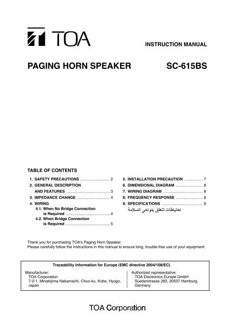
INSTRUCTION MANUAL<br />
<strong>PAGING</strong> <strong>HORN</strong> <strong>SPEAKER</strong><br />
<strong>SC</strong>-<strong>615BS</strong><br />
TABLE OF CONTENTS<br />
1. SAFETY PRECAUTIONS ........................... 2<br />
2. GENERAL DE<strong>SC</strong>RIPTION<br />
AND FEATURES ........................................ 3<br />
3. IMPEDANCE CHANGE .............................. 4<br />
4. WIRING<br />
4.1. When No Bridge Connection<br />
is Required ......................................... 4<br />
4.2. When Bridge Connection<br />
is Required ......................................... 5<br />
5. INSTALLATION PRECAUTION ................. 7<br />
6. DIMENSIONAL DIAGRAM ......................... 8<br />
7. WIRING DIAGRAM ..................................... 8<br />
8. FREQUENCY RESPONSE ......................... 8<br />
9. SPECIFICATIONS ...................................... 9<br />
Thank you for purchasing TOA's Paging Horn Speaker.<br />
Please carefully follow the instructions in this manual to ensure long, trouble-free use of your equipment.<br />
Traceability Information for Europe (EMC directive 2004/108/EC)<br />
Manufacturer:<br />
TOA Corporation<br />
7-2-1, Minatojima Nakamachi, Chuo-ku, Kobe, Hyogo,<br />
Japan<br />
Authorized representative:<br />
TOA Electronics Europe GmbH<br />
Suederstrasse 282, 20537 Hamburg,<br />
Germany
1. SAFETY PRECAUTIONS<br />
• Before installation or use, be sure to carefully read all the instructions in this section for correct and safe<br />
operation.<br />
• Be sure to follow all the precautionary instructions in this section, which contain important warnings and/or<br />
cautions regarding safety.<br />
• After reading, keep this manual handy for future reference.<br />
Safety Symbol and Message Conventions<br />
Safety symbols and messages described below are used in this manual to prevent bodily injury and property<br />
damage which could result from mishandling. Before operating your product, read this manual first and<br />
understand the safety symbols and messages so you are thoroughly aware of the potential safety hazards.<br />
WARNING<br />
Indicates a potentially hazardous situation which, if mishandled, could<br />
result in death or serious personal injury.<br />
When Installing the Unit<br />
• Refer all installation work to the dealer from whom<br />
the speaker was purchased. Installation work<br />
requires extensive technical knowledge and<br />
experience. The speaker may fall off if incorrectly<br />
installed, resulting in possible personal injury.<br />
• Install the speaker only in a location that can<br />
structurally support the full weight of the unit and<br />
mounting bracket. Doing otherwise may result in<br />
the speaker falling down and causing personal<br />
injury and/or property damage.<br />
• When installing the speaker in the snowy area,<br />
take appropriate measures to prevent snow from<br />
lying on the speaker. If the snow lies on it, the<br />
speaker may fall, causing personal injuries.<br />
• Do not use other methods than specified to install<br />
the speaker. Extreme force is applied to the<br />
speaker and the speaker could fall off, possibly<br />
resulting in personal injuries.<br />
• Use screws that are appropriate for the ceiling's or<br />
wall's material and structure. Failure to do so may<br />
cause the speaker to fall, resulting in material<br />
damage and possible personal injury.<br />
• Ensure that all screws are securely tightened. If<br />
they are loose after installation, the speaker could<br />
fall down, possibly resulting in personal injury.<br />
• Do not use anti-rust lubricant. If it contacts resin or<br />
rubber parts, they could deteriorate and cause the<br />
speaker to fall, possibly resulting in personal injury.<br />
• Avoid installing the speaker near seaside or in<br />
locations exposed to corrosive gas. The speaker or<br />
its parts may be subject to corrosion, which might<br />
cause it to fall or result in personal injury.<br />
• Do not install the speaker in indoor swimming pools<br />
or such locations where liquid chemicals are used.<br />
The parts deteriorate if corroded, causing the<br />
speaker to fall, which could result in personal<br />
injury.<br />
When the Unit is in Use<br />
• If any of the following irregularities occurs,<br />
immediately switch off the amplifier's power, and<br />
inform the shop from where the speaker was<br />
purchased. Further using the speaker may result in<br />
fire or electric shock.<br />
· If you detect smoke or a strange smell coming<br />
from the speaker<br />
· If water or any metallic object gets into the<br />
speaker<br />
· If the speaker falls, or the speaker case breaks<br />
• To prevent a fire or electric shock, never open nor<br />
remove the speaker case. Refer all servicing to<br />
your nearest TOA dealer.<br />
• Do not mount the speaker in locations exposed to<br />
constant vibration. The speaker or its mounts can<br />
be damaged by excessive vibration, potentially<br />
causing the speaker to fall, which could result in<br />
personal injury.<br />
2
CAUTION<br />
Indicates a potentially hazardous situation which, if mishandled, could<br />
result in moderate or minor personal injury, and/or property damage.<br />
When Installing the Unit<br />
• Avoid touching the speaker's sharp metal edge to<br />
prevent injury.<br />
• To avoid electric shocks, be sure to switch off the<br />
amplifier's power when connecting speakers.<br />
When the Unit is in Use<br />
• Do not operate the speaker for an extended period<br />
of time with the sound distorting. Doing so may<br />
cause the speaker to heat, resulting in a fire.<br />
• Do not stand or sit on, nor hang down from the<br />
speaker as this may cause it to fall down or drop,<br />
resulting in personal injury and/or property<br />
damage.<br />
• Have the speaker checked periodically by the shop<br />
from where it was purchased. Failure to do so may<br />
result in corrosion or damage to the speaker or the<br />
mounts that could cause it to fall, possibly causing<br />
personal injury.<br />
2. GENERAL DE<strong>SC</strong>RIPTION AND FEATURES<br />
TOA's <strong>SC</strong>-<strong>615BS</strong> Paging horn speaker features an aluminum horn flare and stainless steel bracket for allweather<br />
durability. The TOA's unique oval shape horn enhances excellent speech clarity. Other feature<br />
includes a newly developed diaphragm employing special heat-resistant polyimide film to prevent the<br />
diaphragm from absorbing moisture and deformation. High speaker efficiency has also been realized by<br />
minimizing the gap produced when the diaphragm bobbin is installed in the magnetic circuitry slit. The <strong>SC</strong>-<br />
<strong>615BS</strong> is certified to the European Standard EN 54-24: 2008 and the International Standard ISO 7240-24:<br />
2010, and is compliant with the British Standard BS 5839-8: 2008.<br />
• Compact, highly intelligible speaker suited to public address announcement applications.<br />
• Stainless steel bracket and hardware (screws, bolts), and powder-coated horn ensure superb<br />
weatherproofing and corrosion-resistance.<br />
• Shock-resistant aluminum oval horn.<br />
• Certified to EN 54-24, and ISO 7240-24, and compliant with BS 5839-8.<br />
• Equipped with a large steatite terminal block of screw type and thermal fuse.<br />
• Provided with a cable gland on the terminal cover.<br />
• One cable gland can be added, enabling bridge wiring.<br />
• Impedance change available by a rotary switch located inside the terminal cover.<br />
3
3. IMPEDANCE CHANGE<br />
Input impedance is factory-preset to 670 Ω.<br />
To change the impedance, change the rear panel-mounted rotary switch position using a standard<br />
screwdriver.<br />
Notes<br />
• This speaker is designed to be used for high impedance applications (70 V/100 V). Never connect the<br />
speaker to low impedance line.<br />
• No sound is output from the speaker when the switch is set to the OFF position.<br />
Caution<br />
Never set the switch to "–" position for 100 V line operation, as doing so may result in damage to the speaker.<br />
Line Voltage<br />
Imp.<br />
100 V 70 V<br />
— 15 W 330 Ω<br />
15 W<br />
10 W<br />
5 W<br />
3 W<br />
7.5 W<br />
5 W<br />
2.5 W<br />
1.5 W<br />
670 Ω<br />
1 kΩ<br />
2 kΩ<br />
3.3 kΩ<br />
Bold figures represent factory-preset values.<br />
LINE VOLTAGE<br />
70V 100V IMP.<br />
15W<br />
7.5W<br />
5W<br />
2.5W<br />
1.5W<br />
OFF<br />
15W<br />
10W<br />
5W<br />
3W<br />
330Ω<br />
670Ω<br />
1kΩ<br />
2kΩ<br />
3.3kΩ<br />
4. WIRING<br />
The terminal cover is not mounted to the speaker unit when shipped from the factory.<br />
Note<br />
To complete speaker installation, be sure to attach the terminal cover after finishing cable connections.<br />
If the unit is left without the terminal cover attached, water or moisture may get inside the speaker, causing the<br />
unit malfunction.<br />
4.1. When No Bridge Connection is Required<br />
Unit: mm (in)<br />
Step 1. Strip the speaker cable jacket as shown at right.<br />
Step 2. Run the speaker cable through the cable gland.<br />
8 (0.31)<br />
55 (2.17)<br />
Step 3. Connect the speaker cable according to the polarity indication at the screw terminal.<br />
Terminal cover<br />
Screw<br />
terminal<br />
4<br />
2<br />
Speaker cable<br />
Cable gland<br />
3<br />
EARTH HOT COM<br />
HOT<br />
COM<br />
EARTH<br />
Speaker cable
Step 4. Attach the terminal cover.<br />
Secure the terminal cover using the 4 supplied screws.<br />
In this case, take care not to pinch the wiring, and check that the waterproof gasket is secured into<br />
place.<br />
Note<br />
If wiring or the waterproof gasket is pinched between the terminal cover and the unit case, this causes<br />
water or moisture to get inside the terminal cover.<br />
Terminal cover 5<br />
Cable gland<br />
Screw<br />
Screw<br />
4<br />
Waterproof gasket<br />
Step 5. Securely tighten the cable gland.<br />
Note: If loosely tightened, water or moisture may get inside the terminal cover.<br />
4.2. When Bridge Connection is Required<br />
Step 1. Punch a knockout hole.<br />
Punch out the knockout on the terminal cover by tapping the center of<br />
the knockout with a screwdriver or other tool.<br />
Note<br />
Clean burrs off the knockout hole after removing the knockout.<br />
If the cable gland is attached with the burrs left in the hole, water<br />
may get inside the terminal cover.<br />
Knockout<br />
Terminal cover<br />
5
Step 2. Attach the cable gland to be added.<br />
Notes<br />
• Prepare the cable gland of PG 13.5 size separately.<br />
• Ensure that the cable gland is securely tightened. If loosely tightened, water may get inside the<br />
terminal cover.<br />
Waterproof gasket<br />
Nut<br />
Cable gland<br />
Terminal cover<br />
Step 3. Strip the speaker cable jacket. (Refer to page 4, Step 1.)<br />
Step 4. Run one each of speaker cables through the cable gland.<br />
Terminal cover<br />
4<br />
Speaker cables<br />
Cable glands<br />
Step 5. Connect the speaker cables with the same polarity to each terminal according to the polarity indication<br />
at the screw terminal.<br />
Screw<br />
terminal<br />
5<br />
EARTH HOT COM<br />
EARTH<br />
HOT<br />
COM<br />
Speaker<br />
cables<br />
6
Step 6. Attach the terminal cover.<br />
Secure the terminal cover using the 4 supplied screws.<br />
In this case, take care not to pinch the wiring, and check that the waterproof gasket is secured into<br />
place.<br />
Note<br />
If wiring or the waterproof gasket is pinched between the terminal cover and the unit case, this causes<br />
water or moisture to get inside the terminal cover.<br />
Terminal cover<br />
5 Cable glands<br />
Screw<br />
Screw<br />
4<br />
Waterproof gasket<br />
Step 7. Securely tighten the cable glands.<br />
Note<br />
If loosely tightened, water or moisture may get inside the terminal cover.<br />
5. INSTALLATION PRECAUTION<br />
• When installing the <strong>SC</strong>-<strong>615BS</strong>, be sure the drain hole is positioned<br />
toward the ground. Otherwise, rainwater could enter the speaker<br />
inside, and the aging of parts may cause the unit failure.<br />
[Front view]<br />
Drain hole<br />
Center horn<br />
• Be sure that the bolt projection length from wall surface is less than 12 mm (0.47").<br />
If the length is increased beyond 12 mm (0.47"), the bolt touches the speaker's terminal cover, causing the<br />
speaker mounting angle to be limited.<br />
Less than 12 mm (0.47")<br />
Within 90°<br />
• Do not install the speaker face-up from a horizontal plane. If water accumulates in the horn, this may cause<br />
the speaker malfunction.<br />
7
6. DIMENSIONAL DIAGRAM<br />
172 (6.77)<br />
229 (9.02)<br />
104.5 (4.11)<br />
126 (4.96)<br />
36 (1.42)<br />
130 (5.12)<br />
193 (7.6)<br />
195 (7.68)<br />
141 (5.55)<br />
25 25<br />
(0.98) (0.98)<br />
3-ø9 (0.35)<br />
Unit: mm (in)<br />
7. WIRING DIAGRAM<br />
Thermal fuse (84°C or 183.2°F)<br />
3.3 kΩ<br />
2 kΩ<br />
EARTH<br />
HOT<br />
COM<br />
OFF<br />
1 kΩ<br />
670 Ω<br />
330 Ω<br />
8 Ω<br />
0<br />
Screw<br />
COM<br />
terminal Rotary switch Matching<br />
transformer<br />
(Shown above is the factory default wiring.)<br />
8. FREQUENCY RESPONSE<br />
[dB]<br />
100<br />
90<br />
80<br />
70<br />
60<br />
50<br />
20 50 100 500 1 k 5 k 10 k 20 k<br />
Frequency Response (1 W, 4 m)<br />
[Hz]<br />
8
9. SPECIFICATIONS<br />
Standards Certified to the European Standard EN 54-24:2008<br />
Loudspeaker for voice alarm systems<br />
for fire detection and fire alarm systems<br />
Certification No. 0359-CPD-0109<br />
0359<br />
EN 54-24: 2008<br />
11<br />
0359-CPD-0109<br />
Certified to the International Standard ISO 7240-24: 2010 Sound-system<br />
loudspeakers for fire detection and fire alarm systems<br />
In Compliance with the British Standard BS 5839-8: 2008 14.8<br />
Environment Type Type B (Outdoor applications)<br />
Rated Noise Power 15 W (100 V line and 70 V line)<br />
Rated Impedance 100 V line: 670 Ω (15 W), 1 kΩ (10 W), 2 kΩ (5 W), 3.3 kΩ (3 W)<br />
70 V line: 330 Ω (15 W), 670 Ω (7.5 W), 1 kΩ (5 W), 2 kΩ (2.5 W), 3.3 kΩ (1.5 W)<br />
Sensitivity<br />
109 dB (1 W, 1 m at 500 Hz to 2.5 kHz peak level)<br />
100 dB (1 W, 1 m at 100 Hz to 10 kHz pink noise)<br />
88 dB (1 W, 4 m at 100 Hz to 10 kHz pink noise)<br />
Max.SPL<br />
110 dB (15 W, 1 m at 100 Hz to 10 kHz pink noise)<br />
98 dB (15 W, 4 m at 100 Hz to 10 kHz pink noise)<br />
Frequency Response 315 Hz – 12.5 kHz<br />
Coverage Angle (–6 dB) Horizontal: 360° (500 Hz), 160° (1 kHz), 85° (2 kHz), 45° (4 kHz)<br />
Vertical: 360° (500 Hz), 200° (1 kHz), 115° (2 kHz), 60° (4 kHz)<br />
Operating Temperature –20 ºC to +55 ºC (–4 ºF to +131 ºF)<br />
Dust/Water Protection IP65<br />
Cable Gland Size: PG 13.5<br />
One cable gland is factory-installed.<br />
For bridge connection, one cable gland can be added.*<br />
Cable Connection Screw terminal (Steatite)<br />
Applicable Cable Size Outer diameter: ø8.0 – ø12.5 mm<br />
Conductor:<br />
Solid wire or 7-core wire<br />
No bridge connection: 0.8 – 10 mm 2 (AWG18 – 7) for solid wire,<br />
0.8 – 8 mm 2 (AWG18 – 8) for 7-core wire<br />
Bridge connection: 0.8 – 2.5 mm 2 (AWG18 – 13) for solid wire,<br />
0.8 – 1.5 mm 2 (AWG18 – 15) for 7-core wire<br />
Finish Horn flare: Aluminum, off-white, powder coating<br />
Reflector horn, Trans case, and Terminal cover:<br />
ABS resin, off-white<br />
Bracket, screws and bolts: Stainless steel<br />
Dimensions 172 (w) x 200 (h) x 229 (d) mm (6.77" x 7.87" x 9.02")<br />
Weight<br />
1.5 kg (3.31 lb)<br />
Accessory Terminal cover ..... 1<br />
Option<br />
Swivel bracket: YS-151S (Can be used instead of the supplied bracket.)<br />
Notes<br />
• The design and specifications are subject to change without notice for improvement.<br />
• The specifications data was measured in an anechoic chamber, according to EN 54-24.<br />
• Reference axis: Axis is on the center of horn-mouth and perpendicular to the horn-mouth.<br />
• Reference plane: Plane is on the horn-mouth and perpendicular to the reference axis.<br />
• Horizontal plane: Plane is containing the reference axis and perpendicular to the reference plane.<br />
* Suppliable cable gland's part code and name: 525-52-011-70 Cable gland AVC PGB13.5-12 (GRY)<br />
9
URL: http://www.toa.jp/<br />
533-06-244-30


