Repair welding of elements of the sign "ARBEIT MACHT FREI" of the ...
Repair welding of elements of the sign "ARBEIT MACHT FREI" of the ...
Repair welding of elements of the sign "ARBEIT MACHT FREI" of the ...

Create successful ePaper yourself
Turn your PDF publications into a flip-book with our unique Google optimized e-Paper software.
Eugeniusz Turyk, Agnieszka Żydzik-Białek, Margrit Bormann, Andrzej Jastrzębiowski,<br />
Marta Kościelniak, Tadeusz Kuzio, Bogusław Czwórnóg<br />
<strong>Repair</strong> <strong>welding</strong> <strong>of</strong> <strong>elements</strong> <strong>of</strong> <strong>the</strong> <strong>sign</strong> <strong>ARBEIT</strong> <strong>MACHT</strong> FREI<br />
<strong>of</strong> <strong>the</strong> main gate to <strong>the</strong> former German Nazi concentration<br />
and extermination camp Auschwitz I<br />
Editor’s note<br />
After <strong>the</strong> end <strong>of</strong> <strong>the</strong> Second World War <strong>the</strong> <strong>sign</strong> “<strong>ARBEIT</strong> <strong>MACHT</strong> FREI” on <strong>the</strong> gate<br />
to <strong>the</strong> former German Nazi concentration and extermination camp Auschwitz I became one<br />
<strong>of</strong> <strong>the</strong> most important symbols <strong>of</strong> German Nazi concentration camps, slave labour, inhumane<br />
conditions and mass genocide — <strong>the</strong> Holocaust.<br />
Mieczysław Kościelniak (camp serial number 15261)<br />
“Work squads marching out to work”, Poland, 1950, from<br />
<strong>the</strong> collection <strong>of</strong> <strong>the</strong> Auschwitz-Birkenau State Museum<br />
Fig. 1. Front and back <strong>of</strong> <strong>the</strong> <strong>sign</strong> damaged during <strong>the</strong> <strong>the</strong>ft. Red colour<br />
marks spots where <strong>the</strong> <strong>sign</strong> was cut or where its <strong>elements</strong> were torn<br />
<strong>of</strong>f [1]<br />
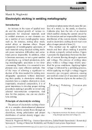
Introduction<br />
In <strong>the</strong> former German Nazi concentration<br />
and extermination camp Auschwitz I in 1940,<br />
a <strong>sign</strong> reading “<strong>ARBEIT</strong> <strong>MACHT</strong> FREI”<br />
(work makes one free) was put up over <strong>the</strong><br />
main gate. The <strong>sign</strong> was made in <strong>the</strong> shop <strong>of</strong><br />
<strong>the</strong> camp’s locksmith under <strong>the</strong> management<br />
<strong>of</strong> Jan Liwacz (camp serial number 1010). At<br />
night, on 17/18 December 2009 <strong>the</strong> <strong>sign</strong> was<br />
stolen from <strong>the</strong> Auschwitz-Birkenau State<br />
Museum in Oświęcim. After recovering it, it<br />
turned out that during <strong>the</strong> <strong>the</strong>ft <strong>the</strong> <strong>sign</strong> (5570<br />
mm in length and 360 mm in height) sustained<br />
<strong>sign</strong>ificant damage – it was cut into three<br />
parts, bent, <strong>the</strong> sections <strong>of</strong> <strong>the</strong> upper<br />
and lower pipes (ϕ 33x3 mm [1])<br />
were twisted and deformed and one<br />
<strong>of</strong> <strong>the</strong> letters (“I” in <strong>the</strong> word FREI)<br />
fell <strong>of</strong>f (Fig. 1).<br />
After <strong>the</strong> <strong>sign</strong> had been recovered,<br />
its exceptional and symbolic<br />
<strong>sign</strong>ificance helped to reach a decision<br />
on correcting <strong>the</strong> <strong>the</strong>ft-related<br />
Mgr Agnieszka Żydzik-Białek, Dipl.-Rest. (FH) Margrit Bormann, mgr Andrzej Jastrzębiowski,<br />
mgr inż. Marta Kościelniak – <strong>the</strong> Auschwitz-Birkenau State Museum in Oświęcim, Conservation<br />
Section; dr hab. inż. Eugeniusz Turyk, mgr inż. Tadeusz Kuzio, dr inż. Bogusław Czwórnóg –<br />
Instytut Spawalnictwa, Gliwice<br />
NR 01/2012<br />
BIULETYN INSTYTUTU SPAWALNICTWA<br />
23
deformities, as <strong>the</strong>y considerably distorted<br />
<strong>the</strong> primary reception <strong>of</strong> <strong>the</strong> <strong>sign</strong>. Afterwards,<br />
all <strong>the</strong> fragments were to be joined to form a<br />
whole <strong>sign</strong> again. Straightening and joining<br />
have an enormous effect on <strong>the</strong> legibility <strong>of</strong><br />
<strong>the</strong> primary functions and meaning <strong>of</strong> <strong>the</strong> <strong>sign</strong>;<br />
<strong>the</strong>refore, <strong>the</strong> activities had to be preceded<br />
by a very thorough investigation. The fundamental<br />
assumption <strong>of</strong> <strong>the</strong> conservation was to<br />
protect all <strong>the</strong> components <strong>of</strong> <strong>the</strong> <strong>sign</strong> – pipes,<br />
letters, welds, and preserve <strong>the</strong> original paint<br />
coatings. At first, <strong>the</strong> conservators thoroughly<br />
documented <strong>the</strong> condition <strong>of</strong> <strong>the</strong> <strong>sign</strong>. In doing<br />
so <strong>the</strong>y used visible light as well as ultraviolet<br />
and infrared photography. The <strong>sign</strong> was<br />
scanned in three dimensions. The tests also<br />
involved analysis <strong>of</strong> <strong>the</strong> chemical composition<br />
and hardness measurements <strong>of</strong> <strong>the</strong> material out<br />
<strong>of</strong> which <strong>the</strong> individual <strong>elements</strong> <strong>of</strong> <strong>the</strong> <strong>sign</strong><br />
were made. Thanks to endoscopy and magnetic<br />
particle inspection it was possible to identify<br />
<strong>the</strong> slightest metal damage, invisible to <strong>the</strong><br />
naked eye. Separate tests were carried out in<br />
relation to <strong>the</strong> protective coatings. All <strong>of</strong> <strong>the</strong>se<br />
activities allowed <strong>the</strong> development <strong>of</strong> a programme<br />
<strong>of</strong> conservation [2].<br />
According to <strong>the</strong> assumptions <strong>of</strong> <strong>the</strong> conservation<br />
programme,<br />
<strong>the</strong> connections<br />
<strong>of</strong> all <strong>the</strong><br />
<strong>elements</strong> <strong>of</strong> <strong>the</strong><br />
<strong>sign</strong> should be<br />
stable, durable,<br />
possibly invisible,<br />
and have no<br />
detrimental effect<br />
on <strong>the</strong> appearance<br />
<strong>of</strong> <strong>the</strong> <strong>sign</strong>. It<br />
was decided that<br />
<strong>the</strong> method employed<br />
to join<br />
Sign<br />
pipe<br />
24 BIULETYN INSTYTUTU SPAWALNICTWA<br />
<strong>the</strong> <strong>elements</strong> should be <strong>the</strong> same as that applied<br />
originally, i.e. <strong>welding</strong>. Such a method should<br />
ensure a relatively narrow heat affected zone,<br />
minimum porosity, and complete penetration<br />
<strong>of</strong> <strong>the</strong> pipe joints (due to changing loads <strong>of</strong> <strong>the</strong><br />
<strong>sign</strong> put up on <strong>the</strong> gate). O<strong>the</strong>r requirements<br />
included entirely crack-free joints and as little<br />
difference in <strong>the</strong> colour <strong>of</strong> <strong>the</strong> welds and <strong>the</strong> parent<br />
metal <strong>of</strong> <strong>the</strong> <strong>elements</strong> made <strong>of</strong> carbon steel.<br />
The Conservation Section <strong>of</strong> <strong>the</strong> Auschwitz<br />
-Birkenau State Museum turned to Instytut<br />
Spawalnictwa with a request to conduct <strong>the</strong>se<br />
works aimed at selecting a technology <strong>of</strong> repair<br />
<strong>welding</strong> <strong>the</strong> <strong>sign</strong> <strong>elements</strong>; <strong>the</strong> technology was<br />
to meet requirements formulated by <strong>the</strong> Conservation<br />
Section. The request also required<br />
technological supervision over <strong>the</strong> repair <strong>welding</strong><br />
<strong>of</strong> <strong>the</strong> <strong>sign</strong> <strong>elements</strong> [5, 6]. The process<br />
and results <strong>of</strong> <strong>the</strong> conservation are presented<br />
below.<br />
Parent metal <strong>of</strong> <strong>sign</strong> <strong>elements</strong><br />
The upper and lower seamed pipes <strong>of</strong> <strong>the</strong> historic<br />
<strong>sign</strong> are made <strong>of</strong> carbon steel having <strong>the</strong><br />
chemical composition as presented in Table 1.<br />
Carbon steel used in <strong>the</strong> production <strong>of</strong> <strong>the</strong><br />
<strong>sign</strong> pipes is characterised by good metallur-<br />
Table 1. Results <strong>of</strong> chemical analysis <strong>of</strong> pipe material [1] and carbon equivalent<br />
Contents <strong>of</strong> chemical <strong>elements</strong> [%]<br />
C Si Mn Cr V Ni Cu<br />
Carbon<br />
equivalent<br />
Ce [%]<br />
upper 0.0585 0.0065 0.3255 0.006 0.002 0.008 0.0228 0.12<br />
lower 0.0956 0.0065 0.4606 0.006 0.002 0.008 0.0203 0.18<br />
Lower pipe – Al content: 0.025%; P content: 0.0218%; S content: 0.0468%.<br />
Upper pipe – Al content: 0.025%; P content: 0.0268%; S content: 0.0661%.<br />
Carbon equivalent: C Mn Cr + Mo + V Ni + Cu<br />
= C + +<br />
+ ,%<br />
6 5 15<br />
Table 2. Results <strong>of</strong> chemical analysis <strong>of</strong> material <strong>of</strong> pipes technological <strong>welding</strong> tests [5]<br />
Test<br />
Contents <strong>of</strong> chemical <strong>elements</strong> [%]<br />
pipe C Si Mn Cr Mo V Ni Cu<br />
Ce [%]<br />
upper 0.065
gical weldability, confirmed by <strong>the</strong> chemical<br />
composition and related carbon equivalent.<br />
For this reason, <strong>welding</strong> <strong>of</strong> <strong>the</strong> steel does not<br />
require any special precautions aimed at preventing<br />
<strong>the</strong> formation <strong>of</strong> hardened structure in<br />
<strong>the</strong> heat affected zone.<br />
On <strong>the</strong> basis <strong>of</strong> a low silicon content<br />
(Si
Fig. 3. End <strong>of</strong> upper part (1GL acc. to 2) after word AR-<br />
BEIT<br />
Fig. 7. 120 mm-long crack <strong>of</strong> lower pipe on section 1DL<br />
acc. to Fig. 2<br />
Fig. 4. Broken end <strong>of</strong> upper pipe (1GP acc. to Fig. 2) before<br />
word <strong>MACHT</strong><br />
Fig. 8. Ends <strong>of</strong> upper and lower pipes (2GL and 2DL acc.<br />
to Fig. 2) after word <strong>MACHT</strong>. Visible bending <strong>of</strong> upper<br />
pipe at angle <strong>of</strong> approx. 90°<br />
Fig. 5. Bent end <strong>of</strong> broken lower pipe (1DL acc. to Fig. 2)<br />
after word <strong>ARBEIT</strong>. Visible deformation <strong>of</strong> letter “T”<br />
Fig. 9. End <strong>of</strong> partly cut and broken upper pipe (2GL acc.<br />
to Fig. 2) after words <strong>MACHT</strong><br />
Fig. 6. End <strong>of</strong> <strong>the</strong> lower pipe (1DL acc. to Fig. 2) partially<br />
cut on along its circumference and <strong>the</strong>n broken<br />
Fig. 10. End <strong>of</strong> partly cut and broken upper pipe (2GP acc.<br />
to Fig. 2) before word FREI<br />
26 BIULETYN INSTYTUTU SPAWALNICTWA<br />
NR 01/2012
Damage was also caused to <strong>the</strong> welded joints<br />
between <strong>the</strong> letters and <strong>the</strong> pipes. During<br />
<strong>the</strong> visual inspection it was possible to notice<br />
cracks – welds partly or fully torn <strong>of</strong>f on <strong>the</strong>ir<br />
whole length. Examples are presented in Figures<br />
12÷15.<br />
Fig. 11. Broken and deformed lower pipe at weld joining<br />
pipe with letter ”I” in word FREI<br />
Fig. 15. Weld joining <strong>the</strong> letter ”I” with upper pipe in<br />
word FREI – letter broken <strong>of</strong>f on <strong>the</strong> whole length <strong>of</strong> welded<br />
joint (part <strong>of</strong> weld remained on pipe)<br />
Fig. 12. Torn <strong>of</strong>f welds joining letter ”R” with lower pipe<br />
in word FREI<br />
It was also possible to observe cracks (Fig.<br />
16) and material torn <strong>of</strong>f along <strong>the</strong> fastening<br />
on <strong>the</strong> right side <strong>the</strong> <strong>sign</strong>.<br />
Fig. 13. Crack (partly torn weld) on <strong>the</strong> length <strong>of</strong> 15 mm<br />
in weld on upper left side <strong>of</strong> letter ”E” in word FREI<br />
Fig. 14. Weld torn <strong>of</strong>f, located on <strong>the</strong> upper right side <strong>of</strong><br />
<strong>the</strong> letter ”E” in word FREI (weld torn <strong>of</strong> on <strong>the</strong> length <strong>of</strong><br />
37.5 mm)<br />
NR 01/2012<br />
BIULETYN INSTYTUTU SPAWALNICTWA<br />
Fig. 16. Cracks in corners <strong>of</strong> right element fastening <strong>sign</strong><br />
to pole – view from <strong>sign</strong> side<br />
In order to eliminate <strong>the</strong> adverse effect <strong>of</strong><br />
rust and protective varnish covering <strong>the</strong> <strong>sign</strong><br />
on <strong>the</strong> quality <strong>of</strong> <strong>the</strong> welded joints after straightening,<br />
prior to <strong>welding</strong> <strong>the</strong> zone directly<br />
adjacent to <strong>the</strong> area <strong>of</strong> planned <strong>welding</strong> underwent<br />
sand-blast cleaning. After removing<br />
paint from <strong>the</strong> existing welds and <strong>the</strong> adjacent<br />
area, it was ascertained that some cracks visible<br />
on <strong>the</strong> surface <strong>of</strong> <strong>the</strong> straightened <strong>elements</strong><br />
were only present in <strong>the</strong> layer <strong>of</strong> <strong>the</strong> paint and<br />
not in <strong>the</strong> metal beneath it. The visual inspection<br />
also revealed <strong>the</strong> presence <strong>of</strong> residual<br />
27
<strong>welding</strong> slag (i.e. slag formed by molten electrode<br />
covering) in <strong>the</strong> welds <strong>of</strong> <strong>the</strong> letters “B”<br />
(from <strong>the</strong> front side <strong>of</strong> <strong>the</strong> <strong>sign</strong>), “E” (from <strong>the</strong><br />
front side <strong>of</strong> <strong>the</strong> <strong>sign</strong>), “I” (from <strong>the</strong> front and<br />
back side <strong>of</strong> <strong>the</strong> <strong>sign</strong>, from <strong>the</strong> bottom) in <strong>the</strong><br />
word <strong>ARBEIT</strong>, “M” (from <strong>the</strong> front side, from<br />
<strong>the</strong> bottom <strong>of</strong> <strong>the</strong> <strong>sign</strong>, from <strong>the</strong> left side) and<br />
<strong>the</strong> letter “C” (from <strong>the</strong> front side, from <strong>the</strong><br />
bottom <strong>of</strong> <strong>the</strong> <strong>sign</strong>), among o<strong>the</strong>rs. On <strong>the</strong> basis<br />
<strong>of</strong> this inspection it was possible to ascertain<br />
that <strong>the</strong> welded joints were welded manually<br />
with covered electrodes. Removal <strong>of</strong> <strong>the</strong><br />
paint revealed <strong>welding</strong> imperfections which<br />
had been formed during <strong>the</strong> original <strong>welding</strong><br />
<strong>of</strong> <strong>the</strong> historic <strong>sign</strong>. These faults included a<br />
burn-through in <strong>the</strong> upper joint <strong>of</strong> <strong>the</strong> letter<br />
“A” in <strong>the</strong> word <strong>ARBEIT</strong> and a gas pore in<br />
<strong>the</strong> welded joint <strong>of</strong> <strong>the</strong> bottom left base <strong>of</strong> <strong>the</strong><br />
letter “R” in <strong>the</strong> same word, from <strong>the</strong> front<br />
side <strong>of</strong> <strong>the</strong> <strong>sign</strong>.<br />
On <strong>the</strong> basis <strong>the</strong> visual inspection <strong>of</strong> <strong>the</strong><br />
<strong>sign</strong>, after its straightening by <strong>the</strong> artistic metalwork<br />
company EDEX-POL in Sułkowice<br />
and sand-blast cleaning <strong>of</strong> <strong>the</strong> zone directly<br />
adjacent to <strong>the</strong> area <strong>of</strong> <strong>the</strong> planned <strong>welding</strong>,<br />
a detailed list <strong>of</strong> <strong>the</strong> necessary repair <strong>welding</strong><br />
was prepared. The scope <strong>of</strong> <strong>the</strong> work included<br />
<strong>the</strong> production <strong>of</strong> butt joints <strong>of</strong> <strong>the</strong> upper and<br />
lower pipes <strong>of</strong> <strong>the</strong> <strong>sign</strong>, <strong>welding</strong> <strong>the</strong> <strong>sign</strong>-fastening<br />
<strong>elements</strong>, as well as <strong>welding</strong> <strong>the</strong> fragments<br />
which had cracked and were torn <strong>of</strong>f<br />
[6].<br />
Tests <strong>of</strong> historic <strong>sign</strong> pipe after hot<br />
straightening<br />
The damaged fragments <strong>of</strong> <strong>the</strong> <strong>sign</strong> underwent<br />
cold or hot straightening. According<br />
to information provided by <strong>the</strong> Conservation<br />
Section, in <strong>the</strong> case <strong>of</strong> hot straightening <strong>the</strong><br />
<strong>elements</strong> were first heated up to a temperature<br />
<strong>of</strong> 830°C÷1050°C (orange colour <strong>of</strong> steel incandescence)<br />
and cooled quickly afterwards.<br />
Visual inspection did not reveal any cracks<br />
in <strong>the</strong> places adjacent to <strong>the</strong> area which had<br />
been heated.<br />
Tests <strong>of</strong> <strong>the</strong> microstructure <strong>of</strong> <strong>the</strong> historic<br />
<strong>sign</strong> pipe were conducted using <strong>the</strong> damaged<br />
section <strong>of</strong> <strong>the</strong> lower pipe, adjacent to <strong>the</strong> letter<br />
“I” (3DP acc. to Fig. 2) in <strong>the</strong> word FREI.<br />
The section in question underwent hot straightening<br />
and next, on <strong>the</strong> basis <strong>of</strong> <strong>the</strong> type<br />
and size <strong>of</strong> <strong>the</strong> damage, was qualified for a<br />
removal and replacement by a 50 mm-long<br />
insert.<br />
Before microstructural analysis <strong>the</strong> pipe<br />
material was tested for <strong>the</strong> contents <strong>of</strong> carbon,<br />
sulphur and phosphorus, which amounted to<br />
0.038%, 0.052% and 0.069% respectively.<br />
The above results, along with <strong>the</strong> results cited<br />
according to <strong>the</strong> study [1], confirmed that<br />
<strong>the</strong> chemical composition <strong>of</strong> <strong>the</strong> pipe being<br />
tested corresponded to low-carbon unalloyed<br />
structural steel. For this reason, after hot straightening<br />
followed by cooling in water, <strong>the</strong><br />
material <strong>of</strong> <strong>the</strong> pipe should be free from disadvantageous<br />
hardened structures. In order<br />
to verify <strong>the</strong> above statement it was necessary<br />
to carry out microscopic metallographic<br />
examination <strong>of</strong> <strong>the</strong> pipe material, revealing<br />
<strong>the</strong> presence <strong>of</strong> ferritic structure with numerous<br />
non-metallic inclusions. The material<br />
<strong>of</strong> <strong>the</strong> pipe after hot straightening and fast<br />
water cooling did not reveal any hardened<br />
structures. The hardness <strong>of</strong> <strong>the</strong> pipe material<br />
measured in <strong>the</strong> metallographic specimen<br />
was between 119 HV10 and 184 HV10. The<br />
microscopic examination and hardness measurements<br />
confirmed that post-straightening<br />
repair <strong>welding</strong> did not require any additional<br />
heat treatment.<br />
28 BIULETYN INSTYTUTU SPAWALNICTWA<br />
NR 01/2012
Initial selection <strong>of</strong> method for <strong>welding</strong><br />
<strong>the</strong> <strong>elements</strong> <strong>of</strong> <strong>the</strong> <strong>sign</strong><br />
The initial selection <strong>of</strong> <strong>the</strong> <strong>welding</strong> method<br />
was based on <strong>the</strong> repair-related requirements<br />
enumerated above and took into consideration<br />
<strong>the</strong> arrangements made with <strong>the</strong> Conservation<br />
Section while preparing expertise and connected<br />
with <strong>the</strong> necessity to ensure a relatively<br />
narrow zone <strong>of</strong> <strong>welding</strong>-related heat effect on<br />
<strong>the</strong> material and paint cover <strong>of</strong> <strong>the</strong> pipe and<br />
a minimum weld reinforcement (aes<strong>the</strong>tical<br />
joint appearance). At this stage also <strong>the</strong> basic<br />
requirements concerning repair <strong>welding</strong> were<br />
specified.<br />
The initial selection <strong>of</strong> <strong>the</strong> repair <strong>welding</strong><br />
method was based on <strong>the</strong> assessment <strong>of</strong> pipe joints<br />
made by means <strong>of</strong> <strong>the</strong> following methods:<br />
oxy-acetylene <strong>welding</strong> (process 311), manual<br />
metal arc <strong>welding</strong> (process 111), semi-automatic<br />
MAG <strong>welding</strong> (process 135), TIG <strong>welding</strong><br />
(process 141), plasma arc <strong>welding</strong> (process 15)<br />
and laser beam <strong>welding</strong> (process 52).<br />
The assessment focused on <strong>the</strong> girth joints<br />
<strong>of</strong> pipes welded at Instytut Spawalnictwa using<br />
oxyacetylene <strong>welding</strong>, manual <strong>welding</strong> with<br />
covered electrodes, TIG <strong>welding</strong> and plasma<br />
arc <strong>welding</strong> as well as joints welded by outside<br />
companies (at <strong>the</strong> request <strong>of</strong> <strong>the</strong> Conservation<br />
Section) with <strong>the</strong> use <strong>of</strong> laser beam <strong>welding</strong>,<br />
MAG <strong>welding</strong> with solid wire electrode, TIG<br />
<strong>welding</strong> and combined <strong>welding</strong> i.e. a penetration<br />
layer and filling layers were made with<br />
TIG <strong>welding</strong> whereas <strong>the</strong> face layer was made<br />
with a laser beam. After analysis <strong>of</strong> <strong>the</strong>se<br />
<strong>welding</strong> methods it was ascertained that <strong>the</strong><br />
methods useful in <strong>the</strong> process <strong>of</strong> making pipe<br />
joints would be TIG <strong>welding</strong>, plasma arc <strong>welding</strong>,<br />
laser <strong>welding</strong> with backing, and a combined<br />
method i.e. penetration by means <strong>of</strong> TIG<br />
<strong>welding</strong> and <strong>the</strong> face layer using laser beam<br />
<strong>welding</strong>. The methods ensured good quality <strong>of</strong><br />
<strong>the</strong> joints <strong>of</strong> <strong>the</strong> <strong>sign</strong>, including <strong>the</strong> pipe joints<br />
with complete penetration, minimum reinforcement<br />
and a relatively narrow heat affected<br />
zone. The torn <strong>of</strong>f letters and <strong>the</strong> cracks in <strong>the</strong><br />
welds joining <strong>the</strong> letters with <strong>the</strong> pipe could be<br />
repaired by means <strong>of</strong> plasma arc <strong>welding</strong> and<br />
TIG <strong>welding</strong> with a filler material, with fillet<br />
welds, <strong>the</strong> same as in <strong>the</strong> case <strong>of</strong> <strong>the</strong> original<br />
<strong>sign</strong>.<br />
Test <strong>welding</strong> <strong>of</strong> pipes nos. 1 and 2 supported<br />
by tests <strong>of</strong> <strong>the</strong> quality <strong>of</strong> welded joints facilitated<br />
<strong>the</strong> selection <strong>of</strong> <strong>welding</strong> consumables<br />
ensuring relatively low porosity <strong>of</strong> welded joints<br />
made <strong>of</strong> effervescing steel. Radiographic<br />
tests revealed <strong>the</strong> quality level B <strong>of</strong> girth joints<br />
made with Castolin Eutectic-manufactured<br />
rods grade CastoTIG 45255, intended for <strong>welding</strong><br />
<strong>of</strong> unalloyed steels and ensuring <strong>the</strong> yield<br />
point <strong>of</strong> weld deposit R0.2 > 385 MPa. The<br />
tensile strength <strong>of</strong> two test pieces <strong>of</strong> <strong>the</strong> joint<br />
from pipe no. 1 was 411.5 MPa and 382.9 MPa<br />
with <strong>the</strong> rupture occurring outside <strong>the</strong> weld.<br />
Positive results <strong>of</strong> radiographic and strength<br />
tests confirmed <strong>the</strong> usability <strong>of</strong> TIG <strong>welding</strong>,<br />
plasma arc <strong>welding</strong> and rods grade CastoTIG<br />
45255W.<br />
The tests also confirmed <strong>the</strong> possibility <strong>of</strong><br />
making irregular decorative spots on <strong>the</strong> faces<br />
<strong>of</strong> welds. The purpose <strong>of</strong> <strong>the</strong>se spots, made<br />
with a pulsed laser, was to mask a characteristic<br />
arrangement <strong>of</strong> crystallisation iso<strong>the</strong>rms<br />
(Fig. 17).<br />
a) b)<br />
Fig. 17. Joint <strong>of</strong> pipes (a) and laser-made decorative spots<br />
on <strong>the</strong> face <strong>of</strong> weld (b)<br />
NR 01/2012<br />
BIULETYN INSTYTUTU SPAWALNICTWA<br />
29
Tests <strong>of</strong> model joints <strong>of</strong> partly torn letters<br />
The <strong>welding</strong> test also involved carrying<br />
out model repair <strong>welding</strong> <strong>of</strong> letters partly and<br />
entirely torn <strong>of</strong>f <strong>the</strong> pipe. At <strong>the</strong> first stage it<br />
was necessary to produce T-shaped joints with<br />
fillet welds, joining <strong>the</strong> letters made <strong>of</strong> 4 mm<br />
-thick steel plate with <strong>the</strong> pipe (33.9x3.2<br />
mm). Afterwards, a passage groove in <strong>the</strong> fillet<br />
weld was made (to model <strong>the</strong> crack in <strong>the</strong><br />
lower and upper part <strong>of</strong> <strong>the</strong> weld). The cuts<br />
were welded with a plasma arc. The technological<br />
conditions <strong>of</strong> plasma <strong>welding</strong> were as<br />
follows: weld groove I, distance 1.0 mm ÷ 1.5<br />
mm, <strong>welding</strong> position PA, tungsten electrode<br />
WTh 20 1.6 mm, plasma gas Ar, shielding<br />
gas Ar+2%H2, filler material – rod CastoTIG<br />
45255W 2.0 mm in diameter, <strong>welding</strong> current<br />
22 A÷26 A, plasma gas flow rate 0.3 l/min ÷<br />
0.4 l/min, shielding gas flow rate 6 l/min. A<br />
sectional view <strong>of</strong> a model crack before and<br />
after <strong>welding</strong> is presented in Figure 18.<br />
a) b)<br />
Fig. 18. Cut in fillet weld, modelling crack along <strong>the</strong> contact<br />
line between letter and pipe (a) and macrostructure <strong>of</strong><br />
plasma-welded cut (b)<br />
The <strong>welding</strong> tests and examinations demonstrated<br />
that <strong>the</strong> cracks in <strong>the</strong> joints between <strong>the</strong><br />
letters and <strong>the</strong> pipe could be repaired by means<br />
<strong>of</strong> plasma arc <strong>welding</strong> and TIG <strong>welding</strong>. The<br />
application <strong>of</strong> <strong>the</strong>se methods ensured proper<br />
fusion and filling <strong>of</strong> <strong>the</strong> weld groove formed<br />
through <strong>the</strong> crack.<br />
Technological supervision<br />
After <strong>the</strong> Conservation Section <strong>of</strong> <strong>the</strong> Museum<br />
had selected a company to perform repair<br />
<strong>welding</strong> i.e. company FormSerwis Sp. z<br />
o.o. (Ltd.) from Bydgoszcz, Instytut Spawalnictwa<br />
carried out <strong>the</strong> following technological<br />
supervisory works:<br />
- verification <strong>of</strong> <strong>welding</strong> procedure specifications<br />
developed by <strong>the</strong> repair <strong>welding</strong> contractor.<br />
The technology developed for <strong>the</strong><br />
<strong>welding</strong> <strong>of</strong> butt joints assumed that <strong>the</strong> root<br />
layer would be TIG welded, whereas <strong>the</strong> face<br />
layer would be laser welded. Afterwards, <strong>the</strong><br />
face <strong>of</strong> <strong>the</strong> weld would be pulsed laser treated<br />
to obtain decorative spots,<br />
- verification <strong>of</strong> qualification certificates <strong>of</strong><br />
personnel performing <strong>the</strong> repair <strong>welding</strong> and<br />
assessment <strong>of</strong> test joints produced within<br />
<strong>the</strong> procedure <strong>of</strong> admission <strong>of</strong> TIG welder<br />
and laser <strong>welding</strong> operator to repair <strong>welding</strong><br />
works,<br />
- pre-<strong>welding</strong> inspection as to <strong>the</strong> completeness<br />
and serviceability <strong>of</strong> <strong>welding</strong> equipment.<br />
- supervision over <strong>the</strong> production <strong>of</strong> <strong>the</strong> joints<br />
<strong>of</strong> <strong>the</strong> <strong>sign</strong> pipes,<br />
- post-weld visual inspection <strong>of</strong> <strong>the</strong> welded<br />
joints <strong>of</strong> <strong>the</strong> <strong>sign</strong>.<br />
Welding station<br />
The <strong>welding</strong> station in a room <strong>of</strong> <strong>the</strong><br />
locksmith’s shop <strong>of</strong> <strong>the</strong> Conservation Section<br />
<strong>of</strong> <strong>the</strong> Museum was equipped by company<br />
FormSerwis Sp. z o.o. with <strong>the</strong> following <strong>welding</strong><br />
equipment:<br />
- device Inverter-TIG-Power 1965 DC-HF<br />
-Puls, manufactured by Italian company CE-<br />
BORA S.p.A., used for TIG <strong>welding</strong>,<br />
- device ALM 200 manufactured by company<br />
ALPHA LASER, Germany, used for laser<br />
<strong>welding</strong> and surfacing by <strong>welding</strong> with a moving<br />
head (Fig. 20), provided with a <strong>welding</strong><br />
30 BIULETYN INSTYTUTU SPAWALNICTWA<br />
NR 01/2012
Fig. 19. Assembly table with fixed <strong>sign</strong><br />
wire feeder. The device is equipped with a<br />
pulsed laser Nd:YAG (wavelength: 1064 nm,<br />
average power 200 W, pulse energy 90 J).<br />
The device is mobile (1400x730x1505 mm,<br />
weight 345 kg), enabling <strong>welding</strong> in various<br />
places, <strong>of</strong>ten difficult to access. The movements<br />
<strong>of</strong> <strong>the</strong> arm with a turn-and-tiltable laser<br />
head are controlled by an operator with a<br />
joystick. Limitations are similar to<br />
those experienced while working<br />
with a TIG <strong>welding</strong> torch.<br />
The <strong>welding</strong> station was also<br />
equipped with an assembly table<br />
provided by <strong>the</strong> Museum Preservation<br />
Department (Fig. 19).<br />
The table was used to fix and position<br />
<strong>the</strong> <strong>sign</strong> while <strong>welding</strong> so<br />
that a joint to be made was in PA<br />
position or a position close to PA<br />
(Fig. 21).<br />
Summary<br />
On <strong>the</strong> basis <strong>of</strong> <strong>the</strong> visual inspection <strong>of</strong> <strong>the</strong><br />
damaged <strong>sign</strong> from <strong>the</strong> main gate to <strong>the</strong> former<br />
German Nazi concentration and extermination<br />
camp Auschwitz I, after its straightening and<br />
sand-blast cleaning, <strong>welding</strong> tests, examination<br />
<strong>of</strong> model joints and technological supervision<br />
over repair <strong>welding</strong>, it was possible<br />
to formulate <strong>the</strong> following conclusions:<br />
Fig. 20. Mobile laser <strong>welding</strong> machine ALM 200<br />
Fig. 21. ALM 200 laser <strong>welding</strong> <strong>of</strong> <strong>sign</strong> fixed on assembly<br />
table<br />
NR 01/2012<br />
BIULETYN INSTYTUTU SPAWALNICTWA<br />
31
1. <strong>Repair</strong> <strong>welding</strong> included <strong>the</strong><br />
production <strong>of</strong> butt joints <strong>of</strong> <strong>the</strong> upper<br />
and lower pipes <strong>of</strong> <strong>the</strong> <strong>sign</strong>, <strong>welding</strong><br />
<strong>of</strong> <strong>the</strong> <strong>sign</strong>-fixing <strong>elements</strong> as well as<br />
<strong>welding</strong> <strong>of</strong> cracks and torn <strong>elements</strong><br />
according to a detailed list prepared<br />
on <strong>the</strong> basis <strong>of</strong> <strong>the</strong> visual inspection<br />
<strong>of</strong> <strong>the</strong> <strong>sign</strong>, following its straightening<br />
and sand-blast cleaning [6].<br />
2. <strong>Repair</strong> <strong>welding</strong> was carried<br />
out by company FormSerwis Sp.<br />
z o.o., following <strong>the</strong> requirements<br />
specified by <strong>the</strong> Conservation Section <strong>of</strong> <strong>the</strong><br />
Auschwitz-Birkenau State Museum [1, 2] and<br />
Instytut Spawalnictwa.<br />
3. Visual inspection <strong>of</strong> <strong>the</strong> repair welded<br />
joints <strong>of</strong> <strong>the</strong> historic <strong>sign</strong> did not reveal any<br />
surface <strong>welding</strong> imperfections and thus confirmed<br />
<strong>the</strong> fulfilment <strong>of</strong> <strong>the</strong> acceptance criteria.<br />
During <strong>the</strong> repair <strong>welding</strong> <strong>the</strong> <strong>sign</strong> did not suffer<br />
from any deformities which would require<br />
straightening. The quality <strong>of</strong> <strong>the</strong> welded joints<br />
<strong>of</strong> <strong>the</strong> <strong>sign</strong> met <strong>the</strong> requirements <strong>of</strong> <strong>the</strong> Conservation<br />
Section <strong>of</strong> <strong>the</strong> Auschwitz-Birkenau<br />
State Museum as to <strong>the</strong> shape, dimensions and<br />
surface appearance.<br />
The conservation, straightening and integration<br />
<strong>of</strong> <strong>the</strong> damaged <strong>sign</strong> were financed<br />
by <strong>the</strong> Auschwitz-Birkenau State Museum in<br />
Oświęcim. All <strong>the</strong> work conducted by Instytut<br />
Spawalnictwa related to material testing,<br />
technology applied for <strong>welding</strong> <strong>of</strong> <strong>the</strong> <strong>sign</strong><br />
<strong>elements</strong>, determination <strong>of</strong> <strong>the</strong> scope <strong>of</strong> repair<br />
<strong>welding</strong> works after straightening <strong>of</strong> <strong>the</strong> <strong>sign</strong>,<br />
and technological supervision over <strong>the</strong> <strong>welding</strong><br />
<strong>of</strong> <strong>the</strong> <strong>sign</strong> [5, 6] were free <strong>of</strong> charge (as<br />
was provided in <strong>the</strong> contract concluded with<br />
<strong>the</strong> Museum).<br />
Prior to its exposition at a new main exhibition<br />
<strong>of</strong> <strong>the</strong> Museum, <strong>the</strong> re-integrated <strong>sign</strong><br />
(Fig. 22) was subjected to fur<strong>the</strong>r conservation.<br />
Fig. 22. Sign after <strong>welding</strong>, removed from assembly table<br />
References<br />
1. Sign <strong>ARBEIT</strong> <strong>MACHT</strong> FREI from <strong>the</strong><br />
main gate to <strong>the</strong> camp AUSCHWITZ I. No.<br />
A-43”. Opracowanie Sekcji Konserwatorskiej<br />
Państwowego Muzeum Auschwitz-Birkenau<br />
w Oświęcimiu, 2010 r.<br />
2. Żydzik-Białek A., Jastrzębiowski A.:<br />
Program prac konserwatorskich. Napis AR-<br />
BEIT <strong>MACHT</strong> FREI z bramy głównej byłego<br />
obozu AUSCHWITZ I. Nr inw. A-43. Sekcja<br />
Konserwatorska Państwowego Muzeum Auschwitz-Birkenau.<br />
2010 r.<br />
3. Photographic documentation <strong>of</strong> <strong>the</strong> current<br />
state <strong>of</strong> <strong>the</strong> object. Conservation Section<br />
<strong>of</strong> <strong>the</strong> Auschwitz-Birkenau State Museum,<br />
Oświęcim, 2011 r.<br />
4. „Mapowanie spawów obrazujące ich<br />
stan zachowania”. Sekcja Konserwatorska<br />
Państwowego Muzeum Auschwitz-Birkenau,<br />
Oświęcim, 2011 r.<br />
5. „Wykonanie badań dotyczących wyboru<br />
technologii spawania elementów napisu AR-<br />
BEIT <strong>MACHT</strong> FREI z bramy głównej byłego<br />
obozu Auschwitz I”. Orzeczenie nr ZT/294/10,<br />
Instytut Spawalnictwa, Gliwice, 2011 r.<br />
6. „Nadzór technologiczny przy spawaniu<br />
naprawczym elementów napisu <strong>ARBEIT</strong><br />
<strong>MACHT</strong> FREI z bramy głównej byłego obozu<br />
Auschwitz I”. Orzeczenie nr ZT/289/11, Instytut<br />
Spawalnictwa, Gliwice, 2011 r.<br />
32 BIULETYN INSTYTUTU SPAWALNICTWA<br />
NR 01/2012