TSA Recommended Security Guidelines for Airport ... - ACConline.org
TSA Recommended Security Guidelines for Airport ... - ACConline.org
TSA Recommended Security Guidelines for Airport ... - ACConline.org

Create successful ePaper yourself
Turn your PDF publications into a flip-book with our unique Google optimized e-Paper software.
NOTICE<br />
THIS PAGE INTENTIONALLY LEFT BLANK<br />
______________________________________________________________________________________________<br />
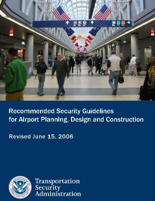
<strong>Recommended</strong> <strong>Security</strong> <strong>Guidelines</strong> <strong>for</strong><br />
<strong>Airport</strong> Planning, Design and Construction<br />
i
NOTICE<br />
NOTICE<br />
This document is distributed under the sponsorship of the Transportation <strong>Security</strong><br />
Administration of the U.S. Department of Homeland <strong>Security</strong> in the interest of<br />
in<strong>for</strong>mation exchange. The U.S. Government assumes no liability <strong>for</strong> the contents<br />
or use.<br />
This document does not create regulatory requirements. There are recommendations and guidelines contained in<br />
this document that might be considered highly beneficial in one airport environment while being virtually<br />
impossible to implement at another airport. The purpose of the document is to provide as extensive a list of options,<br />
ideas, and suggestions as possible <strong>for</strong> the airport architect, designer, planner and engineer to choose from when first<br />
considering security requirements in the early planning and design of new or renovated airport facilities.<br />
This document provides numerous references to and citations from other government and industry sources. These<br />
are not intended to be modified by this document in any way, and are generally intended to refer to the most current<br />
version of such external resources, to which the reader should go <strong>for</strong> detailed in<strong>for</strong>mation.<br />
This document may be downloaded free of charge from the following <strong>TSA</strong> Internet site: http://www.tsa.gov<br />
Or contact the security coordinator at:<br />
<strong>Airport</strong> Consultants Council (ACC): 703-683-5900<br />
<strong>Airport</strong>s Council International – North America (ACI-NA): 202-293-8500<br />
American Association of <strong>Airport</strong> Executives (AAAE): 703-824-0500<br />
______________________________________________________________________________________________<br />
<strong>Recommended</strong> <strong>Security</strong> <strong>Guidelines</strong> <strong>for</strong><br />
<strong>Airport</strong> Planning, Design and Construction<br />
i
THIS PAGE INTENTIONALLY LEFT BLANK<br />
______________________________________________________________________________________________<br />
ii<br />
<strong>Recommended</strong> <strong>Security</strong> <strong>Guidelines</strong> <strong>for</strong><br />
<strong>Airport</strong> Planning, Design and Construction
ACKNOWLEDGEMENTS<br />
ACKNOWLEDGEMENTS<br />
This document is intended to bring to the attention of the airport planning, design, and engineering community the<br />
serious security concerns that must be considered <strong>for</strong> incorporation into an airport design at the earliest possible<br />
planning stage, in order to bring the most efficient and cost-effective security solutions to bear. An undertaking as<br />
extensive and comprehensive as this requires the participation and cooperation of a wide range of aviation security<br />
professionals contributing time, experience, knowledge and insight. We hope that this document accurately captures<br />
the experiences of the past and will help the reader anticipate the needs of the future.<br />
To complete the current revision of this document, an Aviation <strong>Security</strong> Advisory Committee (ASAC) Working<br />
Group was <strong>for</strong>med. Under the auspices of this working group, over 100 persons attended meetings and participated<br />
in document reviews. A few participants, referred to as Section Chiefs, supervised edits of specific sections of the<br />
document. These and other participants rewrote outdated material, edited drafts, and brought current practices, realworld<br />
perspectives and new federal regulations to the table, advising the Working Group of what would, and would<br />
not, work in an operating airport environment.<br />
This document is not intended to be the final word on airport security design; it is meant to be a primer on the<br />
security issues important to airport development and a check-list of the more important things one must consider<br />
when deciding which of the many potential security approaches may be appropriate to a particular airport’s<br />
circumstances and requirements.<br />
We wish to acknowledge the invaluable contribution of all the participating <strong>org</strong>anizations and persons listed below.<br />
Special thanks also go to:<br />
Mike Duffy with the Transportation <strong>Security</strong> Administration (<strong>TSA</strong>), who proposed creation of the working group<br />
and supported this project from start to finish;<br />
Joe Corrao with the <strong>TSA</strong> who served as the Working Group Executive Director;<br />
Joe Kris and Scott Foulger with the <strong>TSA</strong> who served at various times as the <strong>TSA</strong> Working Group Co-Chairs;<br />
Paula Hochstetler with the <strong>Airport</strong> Consultants Council (ACC) who served as the industry Working Group Co-<br />
Chair;<br />
Suzanne Guzik with CTI Consulting who helped assemble and edit the revised draft document;<br />
Bob Mattingly with Sarasota Bradenton International <strong>Airport</strong>, who attended every meeting and made significant<br />
technical contributions to the entire document; and to<br />
The following individuals who served as Section or Appendix Chiefs:<br />
<strong>Airport</strong> Layout & Boundaries - Ken Cox with CTI Consulting<br />
Airside – Ian Redhead with ACI-NA<br />
Landside - Kenneth Hutton with the Metropolitan Washington <strong>Airport</strong>s Authority<br />
Terminal - Art Kosatka with TranSecure<br />
Passenger Screening - Scot Thaxton with the <strong>TSA</strong><br />
Baggage Screening - Mark Torbeck with the <strong>TSA</strong><br />
Cargo Screening - Pam Hamilton with the <strong>TSA</strong><br />
ACAMS - Christer Wilkinson with DMJM Technology<br />
Video Surveillance, Detection & Distribution - James McGuire with MHR International, Inc.<br />
Power, Communication & Cabling Infrastructure - Tom Coleman with DHS TSL & Rebecca Morrison with AAAE<br />
International - James McGuire with MHR International, Inc.<br />
<strong>Airport</strong> Blast Protection - Amber Kasbeer with DHS/<strong>TSA</strong>/TSL & Terry Palmer with Magnusson Klemencic Assoc., Inc.<br />
______________________________________________________________________________________________<br />
<strong>Recommended</strong> <strong>Security</strong> <strong>Guidelines</strong> <strong>for</strong><br />
<strong>Airport</strong> Planning, Design and Construction<br />
iii
ACKNOWLEDGEMENTS<br />
Paula Hochstetler<br />
Ian Redhead<br />
Dean Snyder<br />
Rebecca Morrison<br />
Joe Erhart<br />
Howard Burrows<br />
Mauricio Fernandez<br />
Susan Prediger<br />
Stephen Clarke<br />
Terry Colegrove<br />
Jim Willis<br />
Ken Cox<br />
Suzanne Guzik<br />
Bill Bruneau<br />
Armen DerHohannesian<br />
Jackson Stephens<br />
Dan Ziegelbauer<br />
William A. Fife<br />
Christer Wilkinson<br />
Jozef Grajek<br />
Kelley Fredericks<br />
Rick Marinelli<br />
Steven Urlass<br />
Michael Patrick<br />
Keith Thompson<br />
Marion Kromm White<br />
Mike Bolduc<br />
William Glover<br />
Ron Orchid<br />
Mitch Chokas<br />
Scott Hyde<br />
Theresa Coutu<br />
James Tucci<br />
Michael DiGirolamo<br />
Robert Smallback<br />
Terry Palmer<br />
Dennis Treece<br />
Carl Scarbrough<br />
Geoffrey Baskir<br />
Richard Cullerton<br />
Kenneth Hutton<br />
Jason Terreri<br />
<strong>Airport</strong> Consultants Council<br />
<strong>Airport</strong>s Council Int’l-NA<br />
American Airlines<br />
Amer. Assn of <strong>Airport</strong> Execs<br />
Apple Designs, Inc.<br />
Battelle<br />
Battelle<br />
CAGE Inc.<br />
Carter & Burgess, Inc.<br />
Comm. Infrastructure Designs<br />
Convergent Strategies Consulting<br />
CTI Consulting<br />
CTI Consulting<br />
Denver Int’l <strong>Airport</strong><br />
DerHohannesian + Assoc., LLC<br />
DHS CBP<br />
DHS CBP<br />
DMJM-Harris - NY<br />
DMJM Technology<br />
EJG Aviation<br />
Erie Municipal <strong>Airport</strong> Authority<br />
FAA<br />
FAA<br />
Gensler<br />
Gensler<br />
Gensler<br />
Glover/Resnick & Assoc., Inc.<br />
Glover/Resnick & Assoc., Inc.<br />
Glover/Resnick & Assoc., Inc.<br />
HKS, Inc.<br />
Hartsfield Planning Collaborative<br />
InVision Technologies, Inc.<br />
K&J Safety & <strong>Security</strong> Consulting<br />
Los Angeles World <strong>Airport</strong>s<br />
Lee County Port Auth.<br />
Magnusson Klemencic Assoc.<br />
MassPort Authority<br />
McCarran Int’l <strong>Airport</strong><br />
Metro. Washington <strong>Airport</strong>s Auth.<br />
Metro. Washington <strong>Airport</strong>s Auth.<br />
Metro. Washington <strong>Airport</strong>s Auth.<br />
Metro. Washington <strong>Airport</strong>s Auth.<br />
James McGuire<br />
Michael H. Ross<br />
Mark Forare<br />
Carolyn Strock<br />
Fred Cummings<br />
Shane Shovestull<br />
Jeanne Olivier<br />
G<strong>org</strong>e Reis<br />
Cal Edmonson<br />
Bill Sandifer<br />
Craig Williams<br />
Mike Mini<br />
Frances Sherertz<br />
Donna Edwards<br />
Bob Mattingly<br />
Ted Kleiner<br />
Art Kosatka<br />
Gloria Bender<br />
Eric Miller<br />
Cenk Tunasar<br />
Anthony Cerino<br />
Tom Coleman<br />
Joe Corrao<br />
Michael Duffy<br />
Frederick P. Falcone<br />
Brad Fawsett<br />
Scott Foulger<br />
Pam Hamilton<br />
Amber Kasbeer<br />
David Kasminoff<br />
Rigina Kim<br />
Joseph Kris<br />
Rick Lazarick<br />
Jordan Lerner<br />
Scot Thaxton<br />
Mark Torbeck<br />
Kristina Dores<br />
Michael Pilgrim<br />
Archie Lind<br />
Mike Williams<br />
Franklin M. Sterling<br />
James Williams<br />
MHR International, Inc.<br />
MHR International, Inc.<br />
Miami-Dade Aviation Dept.<br />
Mid-Ohio Valley Regional <strong>Airport</strong><br />
Philadelphia International <strong>Airport</strong><br />
Phoenix Aviation Dept.<br />
Port Authority of NY & NJ<br />
Port Authority of NY & NJ<br />
Raleigh-Durham Int’l <strong>Airport</strong><br />
Reynolds, Smith & Hills, Inc.<br />
Reynolds, Smith & Hills, Inc.<br />
Rhode Island <strong>Airport</strong> Corporation<br />
Sacramento County Apt System<br />
Sandia National Labs<br />
Sarasota Bradenton Int’l Apt<br />
STV Incorporated<br />
TranSecure<br />
TransSolutions<br />
TransSolutions<br />
TransSolutions<br />
<strong>TSA</strong> TSL<br />
<strong>TSA</strong> TSL<br />
<strong>TSA</strong><br />
<strong>TSA</strong><br />
<strong>TSA</strong><br />
<strong>TSA</strong><br />
<strong>TSA</strong><br />
<strong>TSA</strong><br />
<strong>TSA</strong> TSL<br />
<strong>TSA</strong><br />
<strong>TSA</strong><br />
<strong>TSA</strong><br />
<strong>TSA</strong> TSL<br />
<strong>TSA</strong><br />
<strong>TSA</strong><br />
<strong>TSA</strong><br />
Unisys Corp<br />
Unisys Corp<br />
URS Corporation<br />
Williams Gateway <strong>Airport</strong><br />
Williams Sterling, Inc.<br />
Williams Sterling, Inc.<br />
______________________________________________________________________________________________<br />
iv<br />
<strong>Recommended</strong> <strong>Security</strong> <strong>Guidelines</strong> <strong>for</strong><br />
<strong>Airport</strong> Planning, Design and Construction
TABLE OF CONTENTS<br />
TABLE OF CONTENTS<br />
PART I - OVERVIEW<br />
Section A - Introduction ..........................................................................................................1<br />
Section B - Applicability..........................................................................................................1<br />
Section C - Purpose.................................................................................................................2<br />
Section D - Background..........................................................................................................4<br />
Section E - Coordination.........................................................................................................5<br />
Section F - Changing <strong>Security</strong> Concerns and Contingency Measures ..............................6<br />
1. Homeland <strong>Security</strong> Advisory System (HSAS) Threat Conditions .............................................6<br />
2. <strong>TSA</strong> Responsibilities ......................................................................................................................6<br />
3. Planning and Design Considerations...........................................................................................6<br />
PART II - INITIAL PLANNING AND DESIGN CONSIDERATIONS<br />
Section A - General..................................................................................................................7<br />
Section B - Facility Protection................................................................................................8<br />
Section C - Planning Facility Protection................................................................................9<br />
1. <strong>Security</strong> Areas and Boundaries ....................................................................................................9<br />
2. Vulnerability Assessment ............................................................................................................10<br />
3. Protection Criteria ........................................................................................................................11<br />
4. Physical Protection ......................................................................................................................11<br />
5. Crime Prevention ..........................................................................................................................11<br />
6. Recordkeeping..............................................................................................................................11<br />
7. Delegations of Responsibility .....................................................................................................11<br />
8. Design Factors..............................................................................................................................11<br />
______________________________________________________________________________________________<br />
<strong>Recommended</strong> <strong>Security</strong> <strong>Guidelines</strong> <strong>for</strong> May 3, 2006<br />
<strong>Airport</strong> Planning, Design and Construction<br />
v
TABLE OF CONTENTS<br />
PART III - RECOMMENDED GUIDELINES<br />
Section A - <strong>Airport</strong> Layout and Boundaries ........................................................................13<br />
1. General <strong>Airport</strong> Layout..................................................................................................................13<br />
a. Airside ..........................................................................................................................................13<br />
b. Landside.......................................................................................................................................14<br />
c. Terminal........................................................................................................................................14<br />
2. <strong>Security</strong> Areas................................................................................................................................15<br />
a. Air Operations Area (AOA)...........................................................................................................15<br />
b. <strong>Security</strong> Identification Display Area (SIDA)..................................................................................15<br />
c. Secured Area ...............................................................................................................................16<br />
d. Sterile Area...................................................................................................................................16<br />
e. Exclusive Area .............................................................................................................................16<br />
f. <strong>Airport</strong> Tenant <strong>Security</strong> Program (ATSP) Area.............................................................................17<br />
3. Assessment of Vulnerable Areas.................................................................................................17<br />
4. Chemical and Biological Agents..................................................................................................21<br />
5. Boundaries and Access Points....................................................................................................22<br />
a. Physical Barriers ..........................................................................................................................22<br />
1) Fencing.....................................................................................................................................23<br />
2) Buildings...................................................................................................................................26<br />
3) Walls.........................................................................................................................................26<br />
b. Electronic Boundaries ..................................................................................................................27<br />
c. Natural Barriers ............................................................................................................................29<br />
d. Access Points...............................................................................................................................29<br />
1) Gates........................................................................................................................................29<br />
2) Doors........................................................................................................................................30<br />
3) Guard Stations .........................................................................................................................31<br />
4) Electronic Access Points..........................................................................................................31<br />
a) Automatic Gates ...................................................................................................................31<br />
b) Doors with Access Controls..................................................................................................32<br />
c) Sensor Line Gates ................................................................................................................32<br />
d) Automated Portals ................................................................................................................32<br />
5) Vehicle Inspection Stations, Blast Protection, and Road Barriers ...........................................32<br />
e. Other <strong>Security</strong> Measures .............................................................................................................37<br />
1) Fence Clear Zones...................................................................................................................37<br />
2) <strong>Security</strong> Lighting.......................................................................................................................37<br />
3) Locks ........................................................................................................................................37<br />
4) CCTV Coverage .......................................................................................................................38<br />
5) Signage ....................................................................................................................................38<br />
______________________________________________________________________________________________<br />
vi<br />
<strong>Recommended</strong> <strong>Security</strong> <strong>Guidelines</strong> <strong>for</strong><br />
<strong>Airport</strong> Planning, Design and Construction
TABLE OF CONTENTS<br />
6. Facilities, Areas and Geographical Placement...........................................................................41<br />
a. Aircraft Maintenance Facilities .....................................................................................................41<br />
b. Aircraft Movement Areas..............................................................................................................41<br />
c. Aircraft Rescue and Fire Fighting (ARFF) Facilities.....................................................................41<br />
d. <strong>Security</strong> Operations Center (SOC)/<strong>Airport</strong> Emergency Command Post (CP) .............................42<br />
e. <strong>Airport</strong> Personnel Offices .............................................................................................................42<br />
f. Belly Cargo Facility .......................................................................................................................42<br />
g. All-Cargo Area..............................................................................................................................43<br />
h. FAA <strong>Airport</strong> Traffic Control Tower (ATCT) and Offices................................................................43<br />
i. Fuel Facilities.................................................................................................................................43<br />
j. General Aviation (GA) and Fixed Base Operator (FBO) Areas ....................................................43<br />
k. Ground Service Equipment Maintenance (GSEM) Facility ..........................................................43<br />
l. Ground Transportation Staging Area ............................................................................................43<br />
m. Hotels and On-<strong>Airport</strong> Accommodations.....................................................................................44<br />
n. Industrial/Technology Parks.........................................................................................................44<br />
o. In-Flight Catering Facility .............................................................................................................44<br />
p. Intermodal Transportation Area ...................................................................................................44<br />
q. Isolated <strong>Security</strong> Aircraft Parking Position ...................................................................................44<br />
r. Military Facilities............................................................................................................................44<br />
s. Navigational & Communications Equipment................................................................................44<br />
t. Passenger Aircraft Loading/Unloading Parking Areas..................................................................44<br />
u. Passenger Aircraft Overnight Parking Areas ...............................................................................45<br />
v. Rental Car and Vehicle Storage Facilities....................................................................................45<br />
w. State/Government Aircraft Facilities............................................................................................45<br />
x. Terminal Patron Parking Areas ....................................................................................................45<br />
y. Utilities and Related Equipment ...................................................................................................45<br />
Section B - Airside.................................................................................................................47<br />
1. Aircraft Movement and Parking Areas ........................................................................................47<br />
a. Aircraft Movement Areas..............................................................................................................47<br />
b. Passenger Loading/Unloading Aircraft Parking Areas.................................................................47<br />
c. Passenger Aircraft Overnight Parking Areas ...............................................................................47<br />
d. General Aviation (GA) Parking Area ............................................................................................47<br />
e. Isolated/<strong>Security</strong> Parking Position ...............................................................................................48<br />
2. Airside Roads.................................................................................................................................48<br />
3. Airside Vulnerable Areas & Protection........................................................................................48<br />
4. Airside Cargo Areas ......................................................................................................................49<br />
______________________________________________________________________________________________<br />
<strong>Recommended</strong> <strong>Security</strong> <strong>Guidelines</strong> <strong>for</strong> May 3, 2006<br />
<strong>Airport</strong> Planning, Design and Construction<br />
vii
TABLE OF CONTENTS<br />
Section C - Landside .............................................................................................................50<br />
1. Natural Barriers..............................................................................................................................50<br />
2. Landside Roads .............................................................................................................................50<br />
a. Vehicle Inspection Stations..........................................................................................................50<br />
b. Roadway Design ..........................................................................................................................51<br />
3. Landside Parking...........................................................................................................................51<br />
a. Terminal Patron Parking ..............................................................................................................51<br />
b. Employee Parking ........................................................................................................................52<br />
4. Landside Facilities.........................................................................................................................52<br />
a. Ground Transportation Staging Area (G<strong>TSA</strong>)..............................................................................52<br />
b. Hotels and On-<strong>Airport</strong> Accommodations......................................................................................52<br />
c. Intermodal Transportation Area ...................................................................................................52<br />
d. Rental Car and Vehicle Storage Areas ........................................................................................52<br />
5. Entry Control Points (ECPs).........................................................................................................53<br />
a. Gates............................................................................................................................................53<br />
b. Roads...........................................................................................................................................53<br />
6. Interior Spaces...............................................................................................................................53<br />
7. Exterior Spaces..............................................................................................................................53<br />
a. Physical Barriers ..........................................................................................................................53<br />
1) Fencing.....................................................................................................................................53<br />
2) Buildings...................................................................................................................................54<br />
a) Walls .....................................................................................................................................54<br />
b) Exterior Walls........................................................................................................................54<br />
b. Lighting.........................................................................................................................................55<br />
c. Utilities and Related Equipment ...................................................................................................55<br />
8. Systems and Equipment ...............................................................................................................55<br />
a. Electronic Detection and Monitoring ............................................................................................55<br />
b. CCTV............................................................................................................................................55<br />
c. Alarms ..........................................................................................................................................56<br />
9. Emergency Response ...................................................................................................................56<br />
a. Law En<strong>for</strong>cement .........................................................................................................................56<br />
b. Off-<strong>Airport</strong> Emergency Response ................................................................................................56<br />
c. Life Safety Equipment ..................................................................................................................56<br />
d. Emergency Service Coordination ................................................................................................56<br />
e. Threat Containment Unit (TCU) ...................................................................................................56<br />
______________________________________________________________________________________________<br />
viii<br />
<strong>Recommended</strong> <strong>Security</strong> <strong>Guidelines</strong> <strong>for</strong><br />
<strong>Airport</strong> Planning, Design and Construction
TABLE OF CONTENTS<br />
Section D - Terminal..............................................................................................................58<br />
1. Terminal <strong>Security</strong> Architecture ....................................................................................................58<br />
a. Functional Areas ..........................................................................................................................58<br />
b. Physical Boundaries.....................................................................................................................59<br />
c. Bomb/Blast Overview ...................................................................................................................59<br />
d. Limited Concealment Areas/Structures .......................................................................................60<br />
e. Operational Pathways ..................................................................................................................60<br />
f. Minimal Number of <strong>Security</strong> Portals.............................................................................................61<br />
g. Space <strong>for</strong> Expanded, Additional and Contingency Measures......................................................61<br />
2. Terminal Area Users and Infrastructure......................................................................................63<br />
a. Users and Stakeholders...............................................................................................................63<br />
b. Personnel Circulation ...................................................................................................................64<br />
c. Utility Infrastructure ......................................................................................................................64<br />
d. New Construction vs. Alterations .................................................................................................64<br />
3. Sterile Area.....................................................................................................................................65<br />
4. Public Areas ...................................................................................................................................66<br />
a. Public Lobby Areas ......................................................................................................................68<br />
b. Public Emergency Exits ...............................................................................................................70<br />
c. <strong>Security</strong> Doors vs. Fire Doors ......................................................................................................70<br />
d. Concessions Areas ......................................................................................................................70<br />
e. Signage ........................................................................................................................................71<br />
f. Public Lockers...............................................................................................................................73<br />
g. Unclaimed Luggage Facilities ......................................................................................................73<br />
h. VIP Lounges/Hospitality Suites....................................................................................................73<br />
i. Vertical Access..............................................................................................................................73<br />
j. Observation Decks ........................................................................................................................73<br />
5. Nonpublic Areas ............................................................................................................................75<br />
a. Service Corridors, Stairwells and Vertical Circulation..................................................................75<br />
b. <strong>Airport</strong> and Tenant Administrative/Personnel Offices ..................................................................76<br />
c. Tenant Spaces .............................................................................................................................76<br />
d. Law En<strong>for</strong>cement and Public Safety Areas..................................................................................76<br />
1) Public Safety or Police Offices .................................................................................................77<br />
2) Law En<strong>for</strong>cement Parking ........................................................................................................77<br />
3) Remote Law En<strong>for</strong>cement/Public Safety Posts/Areas .............................................................77<br />
4) Other Considerations ...............................................................................................................78<br />
e. Explosives Detection Canine (K-9) Teams and Facilities ............................................................78<br />
f. <strong>Security</strong> Operations Center (SOC) ...............................................................................................78<br />
g. <strong>Airport</strong> Emergency Command Post (CP) .....................................................................................79<br />
1) Location....................................................................................................................................80<br />
2) Space Needs............................................................................................................................80<br />
3) Other Considerations ...............................................................................................................80<br />
h. Family Assistance Center ............................................................................................................80<br />
______________________________________________________________________________________________<br />
<strong>Recommended</strong> <strong>Security</strong> <strong>Guidelines</strong> <strong>for</strong> May 3, 2006<br />
<strong>Airport</strong> Planning, Design and Construction<br />
ix
TABLE OF CONTENTS<br />
______________________________________________________________________________________________<br />
x<br />
i. Federal Inspection Service (FIS) Areas ........................................................................................80<br />
j. Loading Dock & Delivery Areas.....................................................................................................81<br />
6. Common Use Areas.......................................................................................................................84<br />
7. Terminal Vulnerable Areas & Protection.....................................................................................84<br />
8. Chemical and Biological Threats .................................................................................................85<br />
Section E - <strong>Security</strong> Screening.............................................................................................87<br />
1. Passenger <strong>Security</strong> Screening Checkpoints (SSCP).................................................................88<br />
a. General Issues .............................................................................................................................88<br />
b. Regulations and <strong>Guidelines</strong> .........................................................................................................89<br />
c. Essential Coordination .................................................................................................................89<br />
d. Planning Considerations ..............................................................................................................89<br />
1) Level and Type of Risk.............................................................................................................89<br />
2) Operational Types ....................................................................................................................90<br />
3) Location of SSCPs ...................................................................................................................91<br />
4) SSCP Size................................................................................................................................93<br />
e. Elements of the SSCP .................................................................................................................94<br />
f. SSCP Operational Efficiency ......................................................................................................105<br />
1) Designing <strong>for</strong> the Process ......................................................................................................105<br />
2) Length of Response Corridor .................................................................................................106<br />
3) Architectural Design ...............................................................................................................106<br />
4) SSCP Signage .......................................................................................................................106<br />
5) Space <strong>for</strong> <strong>TSA</strong> Staff................................................................................................................106<br />
g. SSCP Layout Standards ............................................................................................................107<br />
h. SSCP Spacing Requirements....................................................................................................112<br />
i. SSCP Project Funding ................................................................................................................112<br />
j. Designing <strong>for</strong> the Future..............................................................................................................112<br />
2. Baggage Screening .....................................................................................................................115<br />
a. Background ................................................................................................................................115<br />
b. Applicable Regulations...............................................................................................................115<br />
1) Regulatory Requirement ........................................................................................................115<br />
2) <strong>TSA</strong> Protocols ........................................................................................................................115<br />
c. Protocols and Concept of Operations ........................................................................................115<br />
1) Checked Baggage Screening Options...................................................................................116<br />
2) ETD and EDS Key Per<strong>for</strong>mance Characteristics...................................................................121<br />
3) Design Goals..........................................................................................................................123<br />
d. Design Mitigation & Lessons Learned .......................................................................................131<br />
1) Avoid Sleep Conveyor Slopes................................................................................................131<br />
2) Manage Belt Speed Transitions .............................................................................................131<br />
3) Photo Eyes Too Close to the Belt ..........................................................................................132<br />
4) Photo Eyes Too Close to the Belt ..........................................................................................133<br />
5) Avoid Static-Plough and Roller Diverters...............................................................................133<br />
6) Use Conveyor Brakes and Variable Frequency Drives (VFD)...............................................134<br />
<strong>Recommended</strong> <strong>Security</strong> <strong>Guidelines</strong> <strong>for</strong><br />
<strong>Airport</strong> Planning, Design and Construction
TABLE OF CONTENTS<br />
7) Avoid Inaccurate Pusher Operation .......................................................................................134<br />
8) Avoid Improper Merging and Too Many Belt Merges ............................................................135<br />
9) Avoid 90-Degree Belt Merges ................................................................................................135<br />
10) Avoid In-Line Decision and Removal Points ........................................................................136<br />
11) Avoid Directly Opposing Diverters .......................................................................................136<br />
12) Lack of a Fail-Safe Decision Point .......................................................................................137<br />
13) Avoid Reinsertion Points between EDS and Decision Point(s)............................................137<br />
14) Avoid Bottlenecks.................................................................................................................138<br />
15) Avoid Using Plexiglas Photo Eye Guards ............................................................................138<br />
16) Avoid Short Reconciliation Lines..........................................................................................139<br />
17) Avoid Non-Powered Rollers .................................................................................................139<br />
18) Avoid Non-Powered Rollers .................................................................................................140<br />
19) Use Tubs When Appropriate................................................................................................140<br />
20) Consider How Bag Orientation to the EDS will be Maintained ............................................141<br />
21) Use Caution with Draft Curtains...........................................................................................142<br />
22) Avoid Tracking without Real-Time Belt Speeds...................................................................142<br />
23) Inefficient Baggage System .................................................................................................142<br />
24) Efficient Baggage System ....................................................................................................143<br />
e. Impact of Various Threat Levels ................................................................................................143<br />
f. Alternate Screening Options (Remote Screening)......................................................................143<br />
1) Remote Baggage Check-In....................................................................................................144<br />
g. Evaluating Design Options.........................................................................................................145<br />
3. Cargo Screening ..........................................................................................................................148<br />
a. Introduction to Cargo <strong>Security</strong> ...................................................................................................148<br />
b. <strong>Airport</strong>-Cargo Processing Facilities............................................................................................148<br />
c. Operational Considerations........................................................................................................148<br />
d. Access Control Considerations..................................................................................................149<br />
e. In<strong>for</strong>mation and Requirement Resources ..................................................................................149<br />
Section F - Access Control and Alarm Monitoring Systems (ACAMS) ..........................150<br />
1. Suggested Support Requirements.............................................................................................150<br />
2. Operational Requirements..........................................................................................................152<br />
3. On-Site Communication Requirements.....................................................................................153<br />
4. Power Requirements ...................................................................................................................154<br />
5. Credential Access Media Requirements & Issues ...................................................................155<br />
6. Identification Systems Requirements .......................................................................................156<br />
7. Special Device Considerations ..................................................................................................156<br />
8. FIS Device Requirements............................................................................................................157<br />
9. Integration with Other Systems..................................................................................................157<br />
10. Command and Control Requirements.....................................................................................159<br />
11. Design Process Outline ............................................................................................................159<br />
______________________________________________________________________________________________<br />
<strong>Recommended</strong> <strong>Security</strong> <strong>Guidelines</strong> <strong>for</strong> May 3, 2006<br />
<strong>Airport</strong> Planning, Design and Construction<br />
xi
TABLE OF CONTENTS<br />
Section G - Video Surveillance, Detection and Distribution Systems ............................162<br />
1. Uses and Purposes of CCTV Systems ......................................................................................162<br />
2. Operational and Technical Issues..............................................................................................162<br />
a. Assessment & Surveillance........................................................................................................162<br />
b. Intelligent Video..........................................................................................................................164<br />
c. Cameras.....................................................................................................................................165<br />
d. Interior ........................................................................................................................................168<br />
e. Exterior.......................................................................................................................................168<br />
f. Lenses........................................................................................................................................168<br />
g. Video Standards.........................................................................................................................169<br />
h.Video Storage .............................................................................................................................169<br />
i. Retrieval and Distribution ............................................................................................................171<br />
j. Video as Evidence.......................................................................................................................172<br />
3. System Design and Infrastructure .............................................................................................172<br />
a. Networks ....................................................................................................................................173<br />
b. Cabling .......................................................................................................................................174<br />
c. Wireless Systems.......................................................................................................................175<br />
d. Choice of Equipment..................................................................................................................177<br />
e. Lighting & Special Operational Conditions.................................................................................177<br />
Section H - Power, Communications & Cabling Infrastructure.......................................180<br />
1. Power ............................................................................................................................................180<br />
2. Communications Infrastructure .................................................................................................181<br />
3. <strong>Security</strong> of <strong>Airport</strong> Networks......................................................................................................184<br />
a. Network Availability ....................................................................................................................184<br />
b. Network <strong>Security</strong> ........................................................................................................................185<br />
c. Network Accessibility..................................................................................................................185<br />
d. In<strong>for</strong>mation Storage Availability .................................................................................................185<br />
4. Future Rough-Ins/Preparations..................................................................................................185<br />
5. Telecom Rooms ...........................................................................................................................186<br />
6. Radio Frequency (RF) .................................................................................................................186<br />
a. Environmental Considerations ...................................................................................................186<br />
1) Electromagnetic Environment ................................................................................................186<br />
2) Physical Environment.............................................................................................................187<br />
b. Regulations ................................................................................................................................187<br />
c. Installation Considerations .........................................................................................................187<br />
d. Unliscensed Wireless LANs.......................................................................................................187<br />
e. Considerations Related to the Use of Radio Frequency ID Devices <strong>for</strong> <strong>Security</strong>......................188<br />
7. In<strong>for</strong>mation Assurance <strong>for</strong> <strong>Airport</strong> (Re)Construction ..............................................................188<br />
a. Threats .......................................................................................................................................188<br />
8. Data Transport Vulnerabilities....................................................................................................188<br />
______________________________________________________________________________________________<br />
xii<br />
<strong>Recommended</strong> <strong>Security</strong> <strong>Guidelines</strong> <strong>for</strong><br />
<strong>Airport</strong> Planning, Design and Construction
TABLE OF CONTENTS<br />
Section I - International Aviation <strong>Security</strong> and Its Implications <strong>for</strong> U.S. <strong>Airport</strong>s .........191<br />
1. Impacts on U.S. <strong>Airport</strong>s of Foreign <strong>Security</strong> Requirements and Initiatives ........................191<br />
2. U.S. FIS and Homeland <strong>Security</strong> Requirements.......................................................................191<br />
a. CBP’s Mission and Requirements .............................................................................................192<br />
b. FIS Space Requirements...........................................................................................................192<br />
c. CBP FIS Flow Process...............................................................................................................192<br />
d. CBP <strong>Airport</strong> Design Review and Construction Management Process.......................................194<br />
e. <strong>Airport</strong> & A&E Responsibilities <strong>for</strong> the Design and Provisioning of FIS Facilities......................196<br />
f. <strong>Airport</strong> FIS Planning and Design Issues .....................................................................................196<br />
g. Lessons Learned from U.S. <strong>Airport</strong>s..........................................................................................198<br />
______________________________________________________________________________________________<br />
<strong>Recommended</strong> <strong>Security</strong> <strong>Guidelines</strong> <strong>for</strong> May 3, 2006<br />
<strong>Airport</strong> Planning, Design and Construction<br />
xiii
TABLE OF CONTENTS<br />
PART IV - APPENDICES<br />
Appendix A - <strong>Airport</strong> Vulnerability Assessment Process<br />
______________________________________________________________________________________________<br />
xiv<br />
Section A - The Vulnerability Assessment............................................................................1<br />
Section B - The Assessment Process ...................................................................................3<br />
Section C - Reducing the Vulnerability of Structures ........................................................11<br />
Section D - Example ..............................................................................................................11<br />
Appendix B - <strong>Airport</strong> <strong>Security</strong> Space Planning<br />
Section A - Introduction ..........................................................................................................1<br />
Section B - Space Planning Aids ...........................................................................................1<br />
1. Planning Passenger Volume ..........................................................................................................1<br />
a. Typical Peak Hour Passengers (TPHP).........................................................................................2<br />
b. Busy Day/Peak Hour (BDPH) ........................................................................................................2<br />
c. Standard Busy Rate (SBR) ............................................................................................................3<br />
d. Busy Hour Rate (BHR)...................................................................................................................3<br />
2. Calculations......................................................................................................................................3<br />
a. Demand Parameters ......................................................................................................................3<br />
b. SSCP Parameters..........................................................................................................................3<br />
c. The Effect of Demand Scale Factor r.............................................................................................4<br />
3. Number of Checkpoints - Centralized (General Configuration)..................................................5<br />
4. Number of Checkpoints - Centralized (X-Ray + Metal Detector).................................................5<br />
5. Number of Checkpoints - Holdroom (X-Ray + Metal Detector) ...................................................6<br />
6. Queue Size........................................................................................................................................7<br />
Appendix C - <strong>Airport</strong> Blast Protection<br />
Section A - Introduction ..........................................................................................................1<br />
1. Why <strong>Airport</strong>s ..................................................................................................................................1<br />
2. Risk Management ............................................................................................................................1<br />
3. Planning Facility Blast Protection..................................................................................................2<br />
Section B - Common <strong>Airport</strong> blast Protection Issues ..........................................................2<br />
Section C – Effective Blast Protection Measures ...............................................................11<br />
Section D - Explosives <strong>Security</strong> Survey..............................................................................23<br />
Section E - Blast Analysis Tools ..........................................................................................24<br />
Appendix D - Checklists of Key Points from Each Section<br />
<strong>Recommended</strong> <strong>Security</strong> <strong>Guidelines</strong> <strong>for</strong><br />
<strong>Airport</strong> Planning, Design and Construction
TABLE OF CONTENTS<br />
Appendix E - Glossary<br />
Appendix F - Bibliography<br />
Appendix G - Chem-Bio Report Card<br />
______________________________________________________________________________________________<br />
<strong>Recommended</strong> <strong>Security</strong> <strong>Guidelines</strong> <strong>for</strong> May 3, 2006<br />
<strong>Airport</strong> Planning, Design and Construction<br />
xv
TABLE OF CONTENTS<br />
FIGURES<br />
Figure II-C-1 - <strong>Security</strong> Areas General Depiction.....................................................................................9<br />
Figure III-A-1 - Chain Link Fence Barbed Wire Configurations............................................................24<br />
Figure III-A-2 - Vertical Bar Fence ...........................................................................................................25<br />
Figure III-A-3 - Fence Post and Rail Rein<strong>for</strong>cement ..............................................................................25<br />
Figure III-A-4 - ASDE Radar......................................................................................................................28<br />
Figure III-A-5 - ASDE Radar & Its Adaptation <strong>for</strong> Surface <strong>Security</strong> and Intrusion Detection ............28<br />
Figure III-A-6 - Types of Road Barriers ...................................................................................................34<br />
Figure III-A-7 - Example of Pop-Up Wedge Vehicle Crash Barrier .......................................................37<br />
Figure III-D-1 - Visual Depiction of Density in Levels of Service..........................................................68<br />
Figure III-E-1 - Sterile Concourse Station SSCP ....................................................................................91<br />
Figure III-E-2 - Holding Area Station SSCP (O&D) .................................................................................92<br />
Figure III-E-3 - Boarding Gate Station SSCP (Small <strong>Airport</strong>)................................................................93<br />
Figure III-E-4 - Typical SSCP Layout and Elements ..............................................................................95<br />
Figure III-E-5 - Typical WTMD Dimensions .............................................................................................96<br />
Figure III-E-6 - Non-Metallic Barrier.........................................................................................................97<br />
Figure III-E-7 - Standard Size and Layout of an X-Ray Implementation ..............................................98<br />
Figure III-E-8 - Typical Divest and Composure Table............................................................................99<br />
Figure III-E-9 - Typical Holding Station .................................................................................................100<br />
Figure III-E-10 - Typical Wanding Station .............................................................................................101<br />
Figure III-E-11 - Typical ETD Machine Layout ......................................................................................102<br />
Figure III-E-12 - Space Required <strong>for</strong> Typical ETP ................................................................................103<br />
Figure III-E-13 - Typical 2-Lane SSCP Designs ....................................................................................107<br />
Figure III-E-14 - Typical 1-Lane SSCP Designs ....................................................................................109<br />
Figure III-E-15 - Typical 2-Lane Long Neck SSCP Design...................................................................110<br />
Figure III-E-16 - Typical 5-Lane SSCP Design ......................................................................................111<br />
Figure III-E-17 - Category 1: Fully Integrated In-Line System............................................................116<br />
Figure III-E-18 - Category 2: In-Line System........................................................................................117<br />
Figure III-E-19 - Category 3: In-Line or Ticket Counter Mounted System ........................................118<br />
Figure III-E-20 - Category 3: Simple In-Line Ticket Counter System ................................................118<br />
______________________________________________________________________________________________<br />
xvi<br />
<strong>Recommended</strong> <strong>Security</strong> <strong>Guidelines</strong> <strong>for</strong><br />
<strong>Airport</strong> Planning, Design and Construction
TABLE OF CONTENTS<br />
Figure III-E-21 - Category 4: Stand-Alone EDS....................................................................................119<br />
Figure III-E-22 - Category 5: Stand-Alone ETD System......................................................................120<br />
Figure III-E-23 - Category 6: Emerging System Technology ..............................................................121<br />
Figure III-E-24 - Photo Eyes Too Close to the Belt ..............................................................................132<br />
Figure III-E-25 - Photo Eyes Too Close to Conveyor Ends .................................................................133<br />
Figure III-E-26 - Roller Diverters (Static Plough not shown)...............................................................133<br />
Figure III-E-27 - Conveyor Brakes and Variable Frequency Drives (VFD is located under the belt)............134<br />
Figure III-E-28 - Inaccurate Pusher Operation......................................................................................134<br />
Figure III-E-29 - Too Many Belt Merges.................................................................................................135<br />
Figure III-E-30 - 90-Degree Belt Merge ..................................................................................................135<br />
Figure III-E-31 - In-Line Decision Points ...............................................................................................136<br />
Figure III-E-32 - Directly Opposing Diverters .......................................................................................136<br />
Figure III-E-33 - Conveyor Section without Decision Point Photo Eye..............................................137<br />
Figure III-E-34 - Avoid Reinsertion Points between EDS and Decision Point(s) ..............................137<br />
Figure III-E-35 - Bottlenecks Caused by Merge....................................................................................138<br />
Figure III-E-36 - Plexiglas Photo Eye Guard .........................................................................................138<br />
Figure III-E-37 - Short Reconciliation Line on Left...............................................................................139<br />
Figure III-E-38 - Non-Powered Rollers...................................................................................................139<br />
Figure III-E-39 - EDS Exit Power Turn ...................................................................................................140<br />
Figure III-E-40 - Irregular Shaped Bags Causing Jams .......................................................................140<br />
Figure III-E-41 - Entrance Point Bag Orientation Jam .........................................................................141<br />
Figure III-E-42 - Well-Designed EDS Entrance Conveyor....................................................................141<br />
Figure III-E-43 - Eliminate Draft Curtains ..............................................................................................142<br />
Figure III-F-1 - Generic Biometric-Based Access Control System.....................................................152<br />
Figure III-G-1 - Examples of Critical Dimensions.................................................................................164<br />
Figure III-G-2 - Dimensions of CCTV Detector Arrays.........................................................................166<br />
Figure III-G-3 - The Electromagnetic Spectrum ...................................................................................177<br />
Figure III-I-1 - Flow Process <strong>for</strong> International Air Passengers Arriving at a U.S. Port of Entry ......193<br />
Appendix A Figure A-1 - CASRAP Assessment Model ...........................................................................2<br />
Appendix A Figure A-2 - Model <strong>for</strong> Assessing Vulnerabilities...............................................................2<br />
______________________________________________________________________________________________<br />
<strong>Recommended</strong> <strong>Security</strong> <strong>Guidelines</strong> <strong>for</strong> May 3, 2006<br />
<strong>Airport</strong> Planning, Design and Construction<br />
xvii
TABLE OF CONTENTS<br />
Appendix A Figure B-1 - Model <strong>for</strong> Assessing Vulnerabilities...............................................................4<br />
Appendix A Figure B-2 - Scenario Evaluation Criteria............................................................................8<br />
Appendix B Figure B-1 - <strong>Recommended</strong> Relationship <strong>for</strong> TPHP Computations from Annual Figures..........2<br />
Appendix B Figure B-2 - Different Arrival Rates to SSCPs - All Cases with 1,380 passengers per hour.......4<br />
Appendix C Figure B-1 - Elevated Roadway ............................................................................................3<br />
Appendix C Figure B-2 - Curbside Drop-Off at Ticketing Level .............................................................4<br />
Appendix C Figure B-3 - Cirbside Pickup at Baggage Claim Level .......................................................4<br />
Appendix C Figure B-4 - Wrapping Process - Kevlar-Carbon Fiber Wrap ............................................5<br />
Appendix C Figure B-5 - Exterior Doors ...................................................................................................6<br />
Appendix C Figure B-6 - Trash Container ................................................................................................7<br />
Appendix C Figure B-7 - Potential Concealment Area at Ticketing Level.............................................7<br />
Appendix C Figure B-8 - Loading Dock ....................................................................................................8<br />
Appendix C Figure B-9 - Fuel Facility .......................................................................................................9<br />
Appendix C Figure B-10 - Air Traffic Control Tower .............................................................................10<br />
Appendix C Figure C-1 - Blast Envelope ................................................................................................12<br />
Appendix C Figure C-2 - FrameGuard Installation Method...............................................................13<br />
Appendix C Figure C-3 - Conventional Window Replacement System...............................................14<br />
Appendix C Figure C-4 - High Energy-Absorbing Cable-Supported Curtain Wall Glazing System .............15<br />
Appendix C Figure C-5 - Column Wrapping Procedure ........................................................................16<br />
Appendix C Figure C-6 - Close-up View of Metal Fabric Catcher System ..........................................17<br />
Appendix C Figure C-7 - Composite Wall of Steel-Plated Walls ..........................................................18<br />
Appendix C Figure C-8 - Catenary Cable Floor Support System.........................................................19<br />
Appendix C Figure C-9 - Vehicle Barrier <strong>for</strong> At-Grade Condition ........................................................20<br />
Appendix C Figure C-10 - Large IED Threat Containment Unit............................................................21<br />
Appendix C Figure C-11 - Small IED Threat Containment Unit ............................................................22<br />
Appendix C Figure C-12 - Blast and Ballistic Screen Assembly <strong>for</strong> Fuel Storage Tanks .................23<br />
______________________________________________________________________________________________<br />
xviii<br />
<strong>Recommended</strong> <strong>Security</strong> <strong>Guidelines</strong> <strong>for</strong><br />
<strong>Airport</strong> Planning, Design and Construction
TABLE OF CONTENTS<br />
TABLES<br />
Table II-C-1 - <strong>Security</strong> Areas Basic Requirements and Descriptions ..................................................10<br />
Table III-A-1 - Fence Types and Fabric ...................................................................................................23<br />
Table III-A-2 - Lethal Radius of Various Explosive Packages...............................................................35<br />
Table III-A-3 - Comparative Effectiveness of Barrier Types..................................................................36<br />
Table III-D-1 - Levels of Service Definitions ...........................................................................................67<br />
Table III-D-2 - Fruin’s Queue Level of Service C = 7-10 sf per person.................................................67<br />
Table III-D-3 - IATA Level of Service C = 11-17 sf per person..............................................................67<br />
Table III-E-1 - Elements of a Standard <strong>TSA</strong> Checkpoint........................................................................94<br />
Table III-E-2 - Currently Approved WTMDs.............................................................................................97<br />
Table III-E-3 - <strong>TSA</strong>-Approved Carry-On Baggage X-Rays .....................................................................99<br />
Table III-E-4 - <strong>TSA</strong>-Approved ETD Machines........................................................................................102<br />
Table III-E-5 - <strong>TSA</strong>-Approved Supplemental X-Rays ...........................................................................104<br />
Table III-E-6 - Typical SSCP Spacing Requirements ...........................................................................112<br />
Table III-E-7 - ETD Key Specification Characteristics .........................................................................121<br />
Table III-E-8 - EDS Key Specification and Per<strong>for</strong>mance Characteristics ..........................................122<br />
Table III-E-9 - EDS Key Baggage Specifications..................................................................................123<br />
Table III-G-1 - Resolution per Minimum Target Dimension in Line-Pairs..........................................163<br />
Table III-G-2 - Horizontal Angular and Linear Field Coverages of Surveillance Cameras...............167<br />
Table III-G-3 - Horizontal and Vertical Resolution of U.S. and European Video Standard ..............169<br />
Table III-G-4 - Examples of Digital Video Storage Options .................................................................171<br />
Table III-G-5 - IEEE Ethernet Standards and Cable Distances <strong>for</strong> Gigabit Service ..........................174<br />
Table III-G-6 - Unlicensed Wireless Network Spectrum Assignments ..............................................175<br />
Appendix A Table B-1 - Examples of Terrorist Attacks and Weapons..................................................6<br />
Appendix A Table B-2 - Examples of Likely Threat Scenarios...............................................................7<br />
Appendix A Table B-3 - Vulnerability Countermeasures ......................................................................10<br />
Appendix C Table C-1 - Examples of Vehicle Explosives Capacity.....................................................12<br />
______________________________________________________________________________________________<br />
<strong>Recommended</strong> <strong>Security</strong> <strong>Guidelines</strong> <strong>for</strong> May 3, 2006<br />
<strong>Airport</strong> Planning, Design and Construction<br />
xix
TABLE OF CONTENTS<br />
THIS PAGE INTENTIONALLY LEFT BLANK<br />
______________________________________________________________________________________________<br />
xx<br />
<strong>Recommended</strong> <strong>Security</strong> <strong>Guidelines</strong> <strong>for</strong><br />
<strong>Airport</strong> Planning, Design and Construction
PART I -OVERVIEW<br />
PART I<br />
OVERVIEW<br />
Section A - Introduction<br />
This document presents recommendations <strong>for</strong> incorporating sound security considerations into the planning, design,<br />
construction, and modification of security-related airport facilities and airport terminal buildings. It consolidates<br />
in<strong>for</strong>mation developed through the participation of the Transportation <strong>Security</strong> Administration (<strong>TSA</strong>) and other<br />
government and aviation industry professionals. The in<strong>for</strong>mation in this document was gained through the<br />
experiences of a broad range of aviation security programs and projects at numerous United States (U.S.) airports,<br />
and through the continuing ef<strong>for</strong>ts of government and industry to develop improved approaches to incorporating<br />
cost-effective security features into the early planning and design of airport facilities. The in<strong>for</strong>mation is presented<br />
here in a single document, which will be revised and updated periodically as regulations, security requirements, and<br />
technology change.<br />
In response to the September 11, 2001 (9/11) terrorist attacks in the U.S., and with the potential <strong>for</strong> future attacks in<br />
this country, Congress passed and signed into law the Aviation and Transportation <strong>Security</strong> Act (A<strong>TSA</strong>), Public Law<br />
107-71, 115 Stat. 597 on November 19, 2001. The A<strong>TSA</strong> established the <strong>TSA</strong> as an operating administration within<br />
the Department of Transportation (DOT), headed by the Under Secretary of Transportation <strong>for</strong> <strong>Security</strong>.<br />
Since that time, the Department of Homeland <strong>Security</strong> (DHS) realigned a patchwork of government activities into a<br />
single department with the primary mission to protect our homeland, resulting in the most significant trans<strong>for</strong>mation<br />
of the U.S. government in over a half-century. To fulfill its mission, DHS identified several goals and objectives<br />
within its Strategic Plan; <strong>TSA</strong> supports these goals and objectives.<br />
There are numerous advantages to incorporating security concerns into airport planning and design at the earliest<br />
phases. Timely consideration of such needs is almost guaranteed to result in cost effective, less obtrusive, and more<br />
efficient security systems. Such systems are less likely to provoke passenger complaints or employee resistance and<br />
are more able to fully meet regulatory and operational requirements. Proper planning can also result in reduced<br />
manpower requirements and consequential reductions in airport and aircraft operator overhead expenses.<br />
A careful review of the prevalent threat environment and consideration of minimum applicable standards prior to<br />
finalization of plans will help to determine an airport’s most appropriate security posture. Such a review may also help to<br />
reduce a later reliance on labor-intensive procedures and equipment. Inclusion of airport security expertise early in the<br />
planning process will result in a better-coordinated and more cost effective approach to security.<br />
This <strong>Recommended</strong> <strong>Security</strong> <strong>Guidelines</strong> document is intended to help the user ensure that security considerations<br />
and requirements are a component of the planning and design of airport infrastructure, facilities and operational<br />
elements.<br />
Section B - Applicability<br />
These recommended guidelines are provided <strong>for</strong> consideration by aviation user-agencies (airport operators, aircraft<br />
operators, airport tenants), airport planners and consultants, designers, architects, and engineers engaged in<br />
renovation and new airport facility planning, design or construction projects. Some of the recommendations<br />
contained in these guidelines may have broad application at many airport facilities, while others may apply only to a<br />
limited number of airports, facilities or security situations. Parties involved in airport security development projects<br />
are encouraged to review these guidelines <strong>for</strong> applicable considerations and coordination since any airport project’s<br />
successful conclusion will have current and future physical and procedural security consequences. In addition, the<br />
concepts found in this document may be considered when per<strong>for</strong>ming assessments of airport security and/or<br />
vulnerability.<br />
Certain portions of this document outline procedural aspects of operational processes, extending beyond the<br />
proposed design and construction concepts. These are integrated here as a brief tutorial in operational subject<br />
matters that may be little known to the designer/architect. The drafters consider it very important to understand the<br />
______________________________________________________________________________________________<br />
<strong>Recommended</strong> <strong>Security</strong> <strong>Guidelines</strong> <strong>for</strong> May 3, 2006<br />
<strong>Airport</strong> Planning, Design and Construction 1
PART I - OVERVIEW<br />
complexities of such processes and the alternatives available to the airport operator – and thus to the designer –<br />
be<strong>for</strong>e a design can appropriately accommodate space allocation, queuing, equipment, power, and communications<br />
requirements, and other security needs. It is hoped that this document will facilitate meaningful discussion between<br />
designers, airport operators and the aircraft operators on ways to meet security requirements in a cost-effective<br />
manner.<br />
This document provides guidelines and recommendations only and is not intended to suggest mandatory measures<br />
<strong>for</strong> any airport. Although this document contains in<strong>for</strong>mation of interest primarily to commercial airports regulated<br />
under Title 49 of the Code of Federal Regulations (CFR), Part 1542 (hereafter referred to as 49 CFR 1542), some<br />
suggestions may be useful <strong>for</strong> consideration by general aviation (GA) airport operators as well.<br />
GA airports may also refer to a document developed by a different ASAC working group in 2004, titled <strong>Security</strong><br />
<strong>Guidelines</strong> <strong>for</strong> General Aviation <strong>Airport</strong>s. To obtain a copy of <strong>Security</strong> <strong>Guidelines</strong> <strong>for</strong> General Aviation <strong>Airport</strong>s,<br />
contact the General Manager <strong>for</strong> General Aviation, Transportation <strong>Security</strong> Administration.<br />
Section I-B - Applicability Checklist:<br />
<strong>Airport</strong>s<br />
• New<br />
• Existing<br />
• Expanding<br />
• Commercial Passenger<br />
• General Aviation<br />
• Major Cargo<br />
• Multi-Modal<br />
Users of this Book<br />
• <strong>Airport</strong> Operators<br />
• Aircraft Operators<br />
• <strong>Airport</strong> Tenants<br />
• Planners<br />
• Designers<br />
• Architects<br />
• Engineers<br />
• Consultants<br />
Projects<br />
• Planning<br />
• Design<br />
• Construction<br />
• Renovation<br />
• Assessment<br />
Facilities<br />
• Terminals<br />
• Cargo/Freight<br />
• Police/Fire<br />
• Maintenance<br />
• Catering<br />
• Roadways/Parking<br />
• Tenant and Other On-<strong>Airport</strong> Facilities<br />
Section C - Purpose<br />
The purpose of this document is to provide guidance <strong>for</strong> professionals responsible <strong>for</strong>, and affected by, the planning<br />
and design of airport facilities. Use of this document at the start of the airport planning and design process helps<br />
ensure that security needs are adequately considered.<br />
This document contains “checklists” to ensure the coordination, consideration and inclusion of security features in<br />
an efficient and effective manner. <strong>Security</strong> features that have been factored into initial airport facility design are<br />
more likely to be cost-effective, better integrated and more operationally useful than those superimposed on existing<br />
structures through add-ons or change orders. Likewise, security features which have been coordinated early in the<br />
planning and design process with the <strong>TSA</strong>, Federal Aviation Administration (FAA) and other concerned regulatory<br />
bodies, as well as with airport tenants (aircraft operators, catering, concessions) and end-users (law en<strong>for</strong>cement,<br />
public safety and regulatory agencies, and airport operations and maintenance personnel) are more likely to be wellreceived<br />
and accepted, and thus more widely used and successful.<br />
These guidelines identify key security concerns and concepts that should be factored into the planning and design of<br />
airport facilities. Essential considerations include:<br />
1. Access to the Air Operations Area (AOA), <strong>Security</strong> Identification Display Area (SIDA) and Secured Area, which are<br />
defined in 49 CFR 1540 and 1542;<br />
______________________________________________________________________________________________<br />
May 3, 2006<br />
<strong>Recommended</strong> <strong>Security</strong> <strong>Guidelines</strong> <strong>for</strong><br />
2 <strong>Airport</strong> Planning, Design and Construction
PART I -OVERVIEW<br />
2. Flow of people from landside to airside and from airside to landside;<br />
3. Efficient security screening of persons and property into sterile areas as described in 49 CFR 1540, including<br />
consideration <strong>for</strong> queuing space during peak loads;<br />
4. Separation of security areas and/or use of required and recommended signage (static and dynamic), as required;<br />
5. Protection of vulnerable areas and assets;<br />
6. Protection of aircraft, people, and property;<br />
7. Blast mitigation measures;<br />
8. Space <strong>for</strong> checked baggage Explosives Detection Systems (EDS) and devices;<br />
9. Space <strong>for</strong> Explosives Trace Detection (ETD) equipment at screening points;<br />
10. Space <strong>for</strong> Explosives Ordnance Disposal (EOD) operations such as robots and Threat Containment Units (TCU).<br />
These guidelines also identify airport areas requiring special attention in the planning process, and are intended to<br />
result in systems that will not hamper operations, cause undue economic burdens, or turn airports into “armed<br />
<strong>for</strong>tresses.” At the same time, the guidelines must not be interpreted to mandate specific requirements to be met by<br />
any airport. There may numerous solutions to any security challenge, and architects, planners, and designers are<br />
urged to examine and consider all potential avenues be<strong>for</strong>e selecting the solution that best addresses their airport’s<br />
needs in a responsive and cost-effective manner.<br />
Users of these guidelines are reminded that the application of physical security equipment and structures (barriers, access<br />
control, screening, and detection equipment) is fully effective only if supported by similarly effective human procedures.<br />
These include access and identification (ID) media systems, challenge procedures, personnel security training and<br />
procedures, maintenance training and procedures, as well as constant supervision and vigilance. Appropriate early<br />
coordination with airport law en<strong>for</strong>cement agencies, fire code officials, building code officials, emergency response<br />
agencies, operations and maintenance personnel, and other end-users should occur <strong>for</strong> effective and efficient airport<br />
security.<br />
This document is designed to be used primarily in digital/electronic <strong>for</strong>m, although it is also easily used by hardcopy<br />
readers. In the electronic version, listings in the Table of Contents are dynamically linked to the internal<br />
section listed. Simply click on the title heading and you will be taken to that section of the document. To return to<br />
the Table of Contents, click the browser’s “back” or “return” button.<br />
Within the body of text throughout the document, you will find language with hyperlinks underlined in blue italics<br />
referring the reader to other related sections and topics. For example, where terminology is being defined and/or<br />
used the first time, or where reference to the complete definition is deemed useful, a hyperlink is provided to that<br />
term’s location in Appendix E - Glossary.<br />
Section I-C - Purpose Checklist:<br />
<br />
Identify Key Concerns & Concepts in order to:<br />
• Restrict access to the AOA, SIDA &<br />
Secured areas<br />
• Control the flow of people<br />
• Provide efficient security screening<br />
• Separate security areas<br />
• Protect vulnerable areas & assets<br />
• Protect aircraft, people & property<br />
• Address blast mitigation measures<br />
• Provide space <strong>for</strong> EDS & ETD devices<br />
• Provide space <strong>for</strong> EOD operations<br />
Identify Early Coordination needs with:<br />
• <strong>Airport</strong> Law En<strong>for</strong>cement<br />
• Emergency Response Agencies<br />
• Fire Code Officials<br />
• Building Code Officials<br />
• Model Code Officials<br />
• Operations and Maintenance Personnel<br />
• Other End-Users<br />
______________________________________________________________________________________________<br />
<strong>Recommended</strong> <strong>Security</strong> <strong>Guidelines</strong> <strong>for</strong> May 3, 2006<br />
<strong>Airport</strong> Planning, Design and Construction 3
PART I - OVERVIEW<br />
Section D - Background<br />
The Aviation <strong>Security</strong> Improvement Act of 1990, Public Law 101-604 directed the FAA to work with the aviation<br />
industry to develop guidelines <strong>for</strong> airport design and construction to allow <strong>for</strong> maximum-security enhancement.<br />
This legislation was influenced by recommendations made by the President’s Commission on Aviation <strong>Security</strong> and<br />
Terrorism and recognized that the designs of many airport structures did not accommodate the application of<br />
appropriate security measures at that time.<br />
The Aviation and Transportation <strong>Security</strong> Act of 2001 (A<strong>TSA</strong>), Public Law 107-71 established the <strong>TSA</strong>. The act<br />
authorizes increased federal responsibility <strong>for</strong> all aspects of aviation security, including a federal take-over of passenger<br />
and baggage screening. The responsibilities of <strong>TSA</strong> were defined further in 2002 with the passage of the Homeland<br />
<strong>Security</strong> Act, Public Law 107-296, which created the DHS. The primary missions of the department include preventing<br />
terrorist attacks within the United States, reducing the vulnerability of the United States to terrorism at home, and<br />
minimizing the damage and assisting in the recovery from any attacks that may occur. DHS’s primary responsibilities<br />
correspond to five major functions established by the bill: in<strong>for</strong>mation analysis and infrastructure protection; chemical,<br />
biological, radiological, nuclear (CBRN), and related countermeasures; border and transportation security; emergency<br />
preparedness and response; and coordination with other parts of the federal government, with state and local governments,<br />
and with the private sector.<br />
Following creation of the DHS and the <strong>TSA</strong>, there has been a focus on protecting the national transportation system<br />
infrastructure as a whole. The federal government has required various agencies to jointly develop national<br />
strategies and plans to ensure an intergraded approach to transportation security. Additional in<strong>for</strong>mation on these<br />
plans and other specific pre-planning considerations should be coordinated with the <strong>TSA</strong> Federal <strong>Security</strong> Director<br />
(FSD) responsible <strong>for</strong> the airport.<br />
Newly available technological tools <strong>for</strong> vulnerability/risk assessment, flow modeling, and bomb blast protection can<br />
reduce guesswork and minimize certain expenditures in new structures. (Refer to Appendix A – <strong>Airport</strong><br />
Vulnerability Assessment Process, Appendix B – <strong>Airport</strong> <strong>Security</strong> Space Planning, and Appendix C – <strong>Airport</strong> Blast<br />
Protection <strong>for</strong> further in<strong>for</strong>mation.)<br />
______________________________________________________________________________________________<br />
May 3, 2006<br />
<strong>Recommended</strong> <strong>Security</strong> <strong>Guidelines</strong> <strong>for</strong><br />
4 <strong>Airport</strong> Planning, Design and Construction
PART I -OVERVIEW<br />
Section E - Coordination<br />
For new construction or extensive renovation, airport facility planners and designers should encourage the early<br />
<strong>for</strong>mation and involvement of an <strong>Airport</strong> <strong>Security</strong> Committee. The committee should include the affected aircraft<br />
operators and tenants, fire code officials, building code officials, local FAA and <strong>TSA</strong>, local emergency response<br />
agencies, aviation security and other regulatory officials. Its role is to assist planners and designers to factor the<br />
appropriate security and safety perspective into designs <strong>for</strong> current security concerns and to accommodate<br />
anticipated long-term expansion and regulatory changes where possible. Early security-oriented reviews of design<br />
plans can alert project managers to potential integrated security approaches that may be effective as well as<br />
operationally and economically suitable. Local security officials, including the <strong>TSA</strong> FSD responsible <strong>for</strong> the airport,<br />
can also assist planners by providing assessments of the security environment. These assessments should focus on<br />
prevalent sources of threat, past history of criminal/violent activities likely to impact airport security, and could<br />
include recommended countermeasures.<br />
Careful attention must be given to coordination with the regulatory requirements found in 49 Code of Federal<br />
Regulations (CFR) 1540, 1542, 1544, 1546 and 1548 (hereafter referred to as 49 CFR 1540, 49 CFR 1542,<br />
49 CFR 1544, 49 CFR 1546 and 49 CFR 1548), and the sometimes-overlapping areas of control and managerial<br />
jurisdiction spelled out in the respective airport’s <strong>Airport</strong> <strong>Security</strong> Program (ASP).<br />
Careful consideration should be given to the needs of law en<strong>for</strong>cement, security, and safety support personnel during<br />
airport facility planning, design, or renovation. Planners and designers are urged to coordinate with local and<br />
federal law en<strong>for</strong>cement and life safety agencies, local emergency response agencies, canine and explosives<br />
ordnance disposal (EOD) response elements, and, where relevant, local representatives of U.S. Federal Inspection<br />
Service (FIS) agencies.<br />
The needs of FIS agencies – U..S. Customs and Border Protection (CBP), U.S. Fish and Wildlife Service (FWS), and<br />
Public Health Service (PHS) – operating at airports are addressed in the CBP <strong>Airport</strong> Technical Design Standards For<br />
Passenger Processing Facilities and separate FWS and PHS standards respectively. These Standards contain the physical<br />
characteristics of the FIS area and set <strong>for</strong>th requirements <strong>for</strong> the design of new or remodeled airport terminal building<br />
facilities to accommodate CBP processing of international passengers and their luggage arriving in the U.S.<br />
The CBP <strong>Airport</strong> Technical Design Standards discuss passenger and baggage flow and terminal building space utilization<br />
including space guidelines <strong>for</strong> processing arriving international passengers and baggage as well as offices, processing<br />
booths, counters, conveyors, security requirements, x-ray systems, access control and other equipment necessary to<br />
support the monitoring, control, and operation of the FIS facility. As of late 2005, the CBP <strong>Airport</strong> Technical Design<br />
Standards were being composed by CBP to incorporate the legacy Agriculture, Customs, and Immigration facility<br />
standards into one set of comprehensive CBP standards that will replace legacy agency standards.<br />
<strong>Airport</strong>s, planning-architectural-engineering firms, and other interested parties should contact CBP Headquarters <strong>for</strong><br />
in<strong>for</strong>mation and guidance relating to the application and interpretation of the Legacy Agency (Agriculture, Customs, and<br />
Immigration) standards on affected airport projects early in the planning and design process.<br />
The reader should refer to the most current FIS guidelines when accommodating those agencies’ requirements in an<br />
airport design. For related in<strong>for</strong>mation contained within this document, refer to Federal Inspection Services Areas on page<br />
80.<br />
Section I-E - Coordination Checklist:<br />
Initial coordination with the <strong>TSA</strong> FSD<br />
Get the early involvement of <strong>Airport</strong> <strong>Security</strong> Committee & others<br />
Assure 49 CFR and ASP requirements are met<br />
Consider the needs of law en<strong>for</strong>cement, emergency response, security and safety support<br />
personnel<br />
Reference CBP <strong>Airport</strong> Technical Design Standards at <strong>Airport</strong>s where FIS areas are involved<br />
______________________________________________________________________________________________<br />
<strong>Recommended</strong> <strong>Security</strong> <strong>Guidelines</strong> <strong>for</strong> May 3, 2006<br />
<strong>Airport</strong> Planning, Design and Construction 5
PART I - OVERVIEW<br />
Section F - Changing <strong>Security</strong> Concerns and Contingency Measures<br />
<strong>Airport</strong> planners and designers are encouraged to consider the potential impact that changing security concerns, as<br />
well as security and safety contingency measures, can have on airport facility design. Planners and designers should<br />
consult with airport security coordinators, airport operators, aircraft operators, <strong>TSA</strong> security and the FAA’s airport<br />
representatives to ensure designs facilitate the implementation of local airport (including affected <strong>for</strong>eign air<br />
carriers) and aircraft operator contingency measure requirements.<br />
1. Homeland <strong>Security</strong> Advisory System (HSAS) Threat Conditions<br />
The U.S. DHS HSAS is composed of five threat conditions, each representing an increasing risk of terrorist<br />
attack:<br />
a. Low Condition GREEN – low risk of terrorist attack<br />
b. Guarded Condition BLUE – general risk of terrorist attack<br />
c. Elevated Condition YELLOW – significant risk of terrorist attack<br />
d. High Condition ORANGE – high risk of terrorist attack<br />
e. Severe Condition RED – severe risk of terrorist attack<br />
2. <strong>TSA</strong> Responsibilities<br />
<strong>Airport</strong> operators, in consultation with their FSD, must develop and incorporate into their <strong>TSA</strong>-approved ASP,<br />
Aviation <strong>Security</strong> (AVSEC) Contingency Plans that are tailored to the airport. AVSEC systems, methods and<br />
procedures should address specific HSAS levels. In developing the plan, the airport operator and FSD must<br />
consider the relative risk to the airport, existing vulnerabilities identified through a vulnerability assessment of<br />
the airport, unique characteristics of the airport, and resources available to the airport.<br />
When the Secretary of the Department of Homeland <strong>Security</strong> declares the nation at an enhanced threat<br />
condition, the airport operator and others must immediately implement the corresponding security measures<br />
contained in the AVSEC Contingency Plan and all appropriate security directives.<br />
In addition, the airport operator is responsible to ensure that an FAA-approved <strong>Airport</strong> Emergency Plan (AEP),<br />
is coordinated with the <strong>TSA</strong> FSD and included in the overall <strong>Airport</strong> Operations Manual <strong>for</strong> FAA certification<br />
of the airport. The AEP will identify the local emergency response agencies (hospitals, emergency medical<br />
services, mutual-aid first responders, military and federal support agencies, etc.) and types of services which<br />
will need to be accommodated and may require additional facilities during emergency conditions.<br />
3. Planning and Design Considerations<br />
Consideration should be given to the systems, methods and procedures that may be required by the airport,<br />
aircraft operators and tenants to implement AVSEC measures approved within their various security programs.<br />
AVSEC measures are intended to be temporary operational security enhancements; however design and<br />
construction of facilities and infrastructure may ensure more efficient implementation or operational control.<br />
Section I-F - <strong>Security</strong> Concerns & Contingency Measures Checklist:<br />
Discuss contingency needs with airport, <strong>TSA</strong>, FAA and aircraft operator officials<br />
Consider potential impact of contingency measures and emergency plans<br />
Consider potential impact on various areas (landside, airside, terminal, etc.)<br />
Consider the latest changes in security concerns<br />
______________________________________________________________________________________________<br />
May 3, 2006<br />
<strong>Recommended</strong> <strong>Security</strong> <strong>Guidelines</strong> <strong>for</strong><br />
6 <strong>Airport</strong> Planning, Design and Construction
PART II – INITIAL PLANNING AND<br />
DESIGN CONSIDERATIONS<br />
PART II<br />
INITIAL PLANNING AND DESIGN CONSIDERATIONS<br />
Section A - General<br />
General planning, design, construction and operational requirements of a commercial airport are established and<br />
overseen by the FAA under airport certification requirements identified in 14 CFR 139. Additional guidance and<br />
in<strong>for</strong>mation is also provided in specific FAA Advisory Circulars (A/C) <strong>for</strong> various elements that need to be<br />
considered from initial planning through completion of a specific project. Since the creation of the <strong>TSA</strong>, the<br />
authority to ensure the inclusion of security systems, methods and procedures within this construction and<br />
operational process is the responsibility of <strong>TSA</strong>.<br />
The Federal <strong>Security</strong> Director (FSD) is the designated <strong>TSA</strong> official that approves the required <strong>Airport</strong> <strong>Security</strong><br />
Program (ASP) document, which identifies how the airport will meet security requirements established by<br />
regulations in 49 CFR 1542. The FSD and local FAA <strong>Airport</strong>s Division officials will be directly involved with the<br />
airport operator and should be consulted during all phases of any project.<br />
Planning <strong>for</strong> security should be an integral part of any project undertaken at an airport. The most efficient and costeffective<br />
method of instituting security measures into any facility or operation is through advance planning and<br />
continuous monitoring throughout the project. Selecting, constructing, or modifying a facility without considering<br />
the security implications of the general public and airport personnel can result in costly modifications and delays.<br />
Physical security approaches should be based on applicable federal, state, and local regulations and policies to<br />
ensure the protection of the general public, airport personnel, and assets (including in<strong>for</strong>mation systems and data).<br />
At a minimum, a physical security approach should include:<br />
1. A vulnerability assessment (refer to Appendix A) to evaluate the security of an existing airport or a<br />
comprehensive security prospectus evaluating a new facility or site;<br />
2. Periodic inspections to ascertain whether a security program and its implementation meet pertinent federal,<br />
state, and local standards or regulations;<br />
3. A comprehensive and continuing security and threat awareness and education ef<strong>for</strong>t to gain the interest, support<br />
and participation of employees, contractors, consultants, and visitors;<br />
4. Implementation of procedures <strong>for</strong> taking immediate, positive and orderly action to safeguard life and assets<br />
during an emergency.<br />
Once a project has been identified, the airport’s planning and design team may consider consulting experts in the<br />
field of civil aviation security. Such expertise is available from several sources, including <strong>TSA</strong>, professional<br />
associations and private consultants. The team should coordinate with the appropriate federal, state and local<br />
security personnel. Coordination should continue through the contracting process, actual construction, installation<br />
and training. Appropriate personnel should be provided with all pertinent in<strong>for</strong>mation, including timelines, status<br />
reports and points of contact.<br />
To ensure a systematic approach to acquiring and analyzing the in<strong>for</strong>mation necessary to support decision-makers in<br />
the protection of assets and the allocation of security resources, all security specialists should refer to the applicable<br />
federal, state, and local requirements and standards referenced in this guide.<br />
Finally, airport security should reflect the risk status and financial resources of an airport. More than 90 percent of<br />
the air carrier airports in the U.S. are small or medium hub airports which may have limited funding and have to<br />
plan their security projects with an eye toward simplicity and manageable cost.<br />
______________________________________________________________________________________________<br />
<strong>Recommended</strong> <strong>Security</strong> <strong>Guidelines</strong> <strong>for</strong> May 3, 2006<br />
<strong>Airport</strong> Planning, Design and Construction 7
PART II – INITIAL PLANNING AND<br />
DESIGN CONSIDERATIONS<br />
Section II-A - General Checklist:<br />
Advance Planning<br />
Continuous Monitoring<br />
Physical <strong>Security</strong> Program<br />
• Vulnerability assessment<br />
• Periodic inspections<br />
• Continuing security awareness/education<br />
• Emergency procedures<br />
Consult with Experts in Aviation<br />
Coordinate with <strong>Security</strong>/Regulatory<br />
Personnel<br />
Refer to Regulatory Requirements &<br />
Standards<br />
Coordinate with the <strong>TSA</strong> FSD<br />
Section B - Facility Protection<br />
The airport has a responsibility to provide a safe operating environment and infrastructure. The extent of facility<br />
protection should be examined by the local <strong>Airport</strong> <strong>Security</strong> Committee, considering the results of a comprehensive<br />
security prospectus of the new facility or vulnerability assessment of the existing facility. High priority should be<br />
placed on protection of the aircraft from the unlawful introduction of weapons, explosives, or other threatening<br />
articles. Refer to Appendix A – <strong>Airport</strong> Vulnerability Assessment Process <strong>for</strong> further in<strong>for</strong>mation.<br />
Perimeter protection (fences, gates, patrol) is the first line of defense in providing physical security <strong>for</strong> personnel,<br />
property, and in<strong>for</strong>mation at a facility.<br />
The second line of defense, and perhaps the most important, is interior controls (e.g., access control, checkpoints).<br />
The monetary value and criticality of the items and areas to be protected, the risk-based threat, the vulnerability of<br />
the facility, and the cost of the controls necessary to reduce that vulnerability will determine the extent of interior<br />
controls.<br />
Section II-B - Facility Protection Checklist:<br />
<strong>Airport</strong> <strong>Security</strong> Committee Review<br />
Perimeter Protection - First Line of Defense<br />
Interior Controls - Second Line of Defense<br />
Cost Analysis<br />
______________________________________________________________________________________________<br />
May 3, 2006<br />
<strong>Recommended</strong> <strong>Security</strong> <strong>Guidelines</strong> <strong>for</strong><br />
8 <strong>Airport</strong> Planning, Design and Construction
PART II – INITIAL PLANNING AND<br />
DESIGN CONSIDERATIONS<br />
Section C - Planning Facility Protection<br />
The objective of planning facility protection is to ensure both the integrity and continuity of operations and the<br />
security of assets.<br />
1. General <strong>Security</strong> Areas and Boundaries<br />
Several elements or components of an airport operation should be considered when planning <strong>for</strong> the protection of an<br />
airport facility. Figure II-C-1 below is a general depiction of the different areas at a typical commercial airport, such<br />
as a terminal, aircraft apron, runways or taxiways, and many other components which are typically more<br />
comprehensively shown on an FAA-approved <strong>Airport</strong> Layout Plan (ALP). The ALP might be one of the first<br />
documents suggested <strong>for</strong> review that will show the airport property and the facilities at a particular airport.<br />
Figure II-C-1 - <strong>Security</strong> Areas General Depiction<br />
a. Establishment of <strong>Security</strong> Areas and Boundaries<br />
Any area designated as requiring control <strong>for</strong> security and/or safety purposes must have identifiable<br />
boundaries <strong>for</strong> that area to be recognized and managed. In some cases, boundaries must meet a regulatory<br />
requirement to prevent or deter access to an area, but in many instances, boundaries may not be hard<br />
physical barriers, such as fences or walls; they might instead be painted lines, lines marked and monitored<br />
by electronic signals, grass or pavement edges, natural boundaries such as water or tree lines, or simply<br />
geographic coordinates.<br />
______________________________________________________________________________________________<br />
<strong>Recommended</strong> <strong>Security</strong> <strong>Guidelines</strong> <strong>for</strong> May 3, 2006<br />
<strong>Airport</strong> Planning, Design and Construction 9
PART II – INITIAL PLANNING AND<br />
DESIGN CONSIDERATIONS<br />
b. <strong>Security</strong> Areas Basic Requirements(refer to 501H<strong>Security</strong> Area Descriptions on page 15 <strong>for</strong><br />
additional in<strong>for</strong>mation)<br />
Table II-C-1 below provides general comparative descriptions and regulatory requirements (including<br />
training, criminal history record checks (CHRC), and ID display) <strong>for</strong> the three basic airport security areas:<br />
Secured Area, SIDA, and AOA. Please discuss security areas at a specific airport with the local airport<br />
security coordinator and local FSD <strong>for</strong> further clarification. Note: Some designers use the term ‘restricted<br />
area’, but that is a broad generic term and does not carry a specific definition in U.S. airport regulations.<br />
(refer to <strong>Security</strong> Area Descriptions on page 15 <strong>for</strong> additional in<strong>for</strong>mation)<br />
Table II-C-1 - <strong>Security</strong> Areas Basic Requirements and Descriptions<br />
Secured Area SIDA AOA<br />
Regulatory<br />
Requirements<br />
Requires:<br />
1) Access controls meeting<br />
49 CFR 1542.207<br />
per<strong>for</strong>mance standards<br />
2) <strong>Security</strong> Training<br />
3) Full CHRC<br />
4) ID Display/Challenge<br />
Requires:<br />
1) No access control<br />
required<br />
2) <strong>Security</strong> Training<br />
3) Full CHRC<br />
4) ID Display/<br />
Challenge<br />
Requires:<br />
1) Basic access<br />
controls meeting<br />
49 CFR 1542<br />
2) Provide <strong>Security</strong><br />
in<strong>for</strong>mation<br />
Securtiy<br />
Level<br />
Relational<br />
Description<br />
Relatively high level of<br />
security including access<br />
controls, training, CHRC<br />
and ID display/challenge.<br />
A Secured area is always a<br />
SIDA, because all 3 required<br />
SIDA elements are present-<br />
Training, CHRC, and ID<br />
display/challenge. However,<br />
the Secured Area goes<br />
beyond SIDA by also requiring<br />
access controls.<br />
SIDA relates to ID<br />
display and CHRC<br />
only. Access controls<br />
are determined by<br />
requirements of AOA<br />
or secured area<br />
location in relation in<br />
to the SIDA.<br />
SIDA lacks access<br />
controls, so a SIDA,<br />
by itself, cannot, be<br />
a secured area.<br />
Broadest application<br />
of security;<br />
requirements are<br />
not specifically set<br />
<strong>for</strong>th in 1542.<br />
The AOA requires<br />
only basic access<br />
controls, but sets no<br />
specific standards.<br />
2. Vulnerability Assessment<br />
A vulnerability assessment can be an excellent tool to assist in determining the extent to which a facility may<br />
require security enhancements, and serves to bring security considerations into the mix early in the design<br />
process rather than as a more expensive retrofit. Many tools and methodologies are available; all are subjective<br />
to varying degrees, largely because in every case, one must first have a firm grasp of both short and long term<br />
threat in order to ask the necessary first three questions: “What is the threat”, “What is an airport’s level of<br />
vulnerability relative to that threat”, and “To what extent will the threat/vulnerability change” The planning<br />
and design team’s response to these questions will be a recommendation of a combination of security measures,<br />
both physical and procedural, seeking balance between strong security and ease of movement <strong>for</strong> both<br />
______________________________________________________________________________________________<br />
May 3, 2006<br />
<strong>Recommended</strong> <strong>Security</strong> <strong>Guidelines</strong> <strong>for</strong><br />
10 <strong>Airport</strong> Planning, Design and Construction
PART II – INITIAL PLANNING AND<br />
DESIGN CONSIDERATIONS<br />
passengers and employees. Refer to Vulnerable Areas on page 17 and Appendix A – <strong>Airport</strong> Vulnerability<br />
Assessment Process <strong>for</strong> further in<strong>for</strong>mation.<br />
3. Protection Criteria<br />
The <strong>Airport</strong> <strong>Security</strong> Committee may offer recommendations on the level of normal protective service, and may<br />
consider the following:<br />
a. Known threat(s) specific to the airport and/or to the airlines serving it;<br />
b. History of criminal or disruptive incidents in the area surrounding the facility, but not primarily directed<br />
toward airport operations;<br />
c. National threats and the general integrity of U.S. Transportation<br />
d. Facility location, size, and configuration;<br />
e. Extent of exterior lighting;<br />
f. Presence of physical barriers;<br />
g. Presence of access control and alarm monitoring systems (ACAMS), closed-circuit television (CCTV)<br />
systems, and other electronic monitoring systems;<br />
h. Presence and capabilities of on-site staff and/or security patrols; and<br />
i. Other locally determined pertinent factors, such as general aviation (GA), commercial operations, etc.<br />
4. Physical Protection<br />
<strong>Airport</strong>s and aircraft operators provide normal and special protection through a combination of: mobile patrol or<br />
fixed posts staffed by police, other security officers, or contract uni<strong>for</strong>med personnel; security systems and<br />
devices; lockable building entrances and gates; and cooperation of local law en<strong>for</strong>cement agencies. The degree<br />
of normal and special protection is determined by completion of a vulnerability assessment and crime<br />
prevention assessment. Refer to Appendix A <strong>for</strong> further in<strong>for</strong>mation.<br />
5. Crime Prevention<br />
The local police department may collect and compile in<strong>for</strong>mation about criminal activity on or against property<br />
under the control of the airport, provide crime prevention in<strong>for</strong>mation programs to occupant and federal<br />
agencies upon request, and conduct crime prevention assessments in cooperation with appropriate law<br />
en<strong>for</strong>cement agencies.<br />
6. Recordkeeping<br />
In addition to physical protection and other protection and prevention criteria, airports may also have a need to<br />
keep records of incidents, personnel access, or other activities. Some of the records (such as personnel access)<br />
may be maintained automatically and/or electronically. In such cases, recordkeeping needs may affect designs<br />
and equipment locations as well as require considerations <strong>for</strong> secure data storage and should be coordinated<br />
early in the design process.<br />
7. Delegations of Responsibility<br />
Some security responsibilities under 49 CFR 1542 may be transferred to a tenant or aircraft operator. Normally,<br />
the airport will retain responsibility <strong>for</strong> law en<strong>for</strong>cement, monitoring of alarms, requests <strong>for</strong> criminal<br />
investigations, and fire and facility safety and health inspections. This type of agreement between airport and<br />
aircraft operator is known as an Exclusive Area Agreement, or in the case of other airport tenants, an <strong>Airport</strong><br />
Tenant <strong>Security</strong> Program (ATSP). There may also be Letters of Understanding among nearby jurisdictions to<br />
provide assistance to each other during emergencies, but typically these are simply promises to give aid, not<br />
delegations of authority.<br />
8. Design Factors<br />
It is important to consider security systems and procedures from the design phase on, so that space allocation,<br />
appropriate cabinetry and furnishings, conduit runs and system wiring, heavy-duty materials, rein<strong>for</strong>cing<br />
devices, seismic requirements, and other necessary construction requirements are provided in the original plans.<br />
______________________________________________________________________________________________<br />
<strong>Recommended</strong> <strong>Security</strong> <strong>Guidelines</strong> <strong>for</strong> May 3, 2006<br />
<strong>Airport</strong> Planning, Design and Construction 11
PART II – INITIAL PLANNING AND<br />
DESIGN CONSIDERATIONS<br />
Consideration of seismic requirements may seem out of place in a security guideline document. However,<br />
continuity of operations is a paramount concern in design and construction of an airport facility. For this reason<br />
a brief discussion of seismic requirements appears in Seismic Requirements on page 20.<br />
Section II-C - Planning Facility Protection Checklist:<br />
Ensure Integrity & Continuity of Operations<br />
Ensure the <strong>Security</strong> of Assets & Facilities<br />
Protection Criteria<br />
• Facility Location, Size & Configuration<br />
• Known Threats<br />
• History of Incidents<br />
• Amount of Lighting<br />
• Presence of Physical Barriers<br />
• Local Pertinent Factors<br />
Physical Protection<br />
• Mobile Patrols<br />
• Guard Stations<br />
• <strong>Security</strong> Systems<br />
• Lockable Access Points<br />
• Local Law En<strong>for</strong>cement Support<br />
Crime Prevention<br />
Recordkeeping<br />
Delegations of Responsibility<br />
• Exclusive Area Agreements<br />
• <strong>Airport</strong> Tenant <strong>Security</strong> Programs<br />
• Letters of Understanding<br />
Design Factors<br />
• Conduit Runs<br />
• Architectural Conflicts<br />
• Wiring Requirements<br />
• Heavy-load Equipment<br />
• Effects on Passenger Flow<br />
• Construction Equipment Needs<br />
• Large-size Material Delivery<br />
• Seismic Requirements<br />
______________________________________________________________________________________________<br />
May 3, 2006<br />
<strong>Recommended</strong> <strong>Security</strong> <strong>Guidelines</strong> <strong>for</strong><br />
12 <strong>Airport</strong> Planning, Design and Construction
PART III – RECOMMENDED GUIDELINES<br />
SECTION A – LAYOUT & BOUNDARIES<br />
PART III<br />
RECOMMENDED GUIDELINES<br />
Section A - <strong>Airport</strong> Layout and Boundaries<br />
The first step in the integration of security into airport planning, design or major renovation is the analysis and<br />
determination of the airport’s general security requirements, layout and boundaries. These decisions are critical to<br />
the efficient, safe and secure operation of an airport. While existing airports may not have great leeway in<br />
redesigning the general layout, adjustments to the location of access roads or types of boundaries <strong>for</strong> security areas<br />
may be beneficial and integrated into adjacent construction projects. Periodic review of an airport’s boundary<br />
system and locations is recommended to assure that the airport’s needs are met, particularly since aviation security<br />
requirements and surrounding environments may frequently change.<br />
1. General <strong>Airport</strong> Layout<br />
The general layout of an airport consists of three (3) areas generally referred to in the industry as Airside,<br />
Landside, and Terminal. While the terminal area generally lies on the boundary of the airside and landside (as<br />
may other buildings), due to the nature of its use and the special requirements that apply to airport terminals, it<br />
is best treated <strong>for</strong> security purposes as a distinct area.<br />
Each major area of the airport (airside, landside, terminal) has its own special requirements. Airside/landside<br />
requirements and operational parameters should be carefully considered when planning and designing a new<br />
airport or facility. The requirements, barrier and boundary measures that delineate airside from landside, may<br />
have major effects on the facility’s efficiency, employee and public accessibility, and overall aesthetics.<br />
Maintaining the integrity of airside/landside boundaries plays a critical role in reducing unauthorized access to,<br />
attacks on, or the introduction of dangerous devices aboard, passenger aircraft. Effective airside security relies<br />
heavily on the integrated application of physical barriers, identification and access control systems, surveillance<br />
or detection equipment, the implementation of security procedures, and efficient use of resources.<br />
a. Airside<br />
The airside of an airport is the movement area of an airport, adjacent terrain and buildings or portions<br />
thereof, access to which is controlled. Typically, the airside is beyond the security screening stations and<br />
restricting perimeters (fencing, walls or other boundaries) and includes runways, taxiways, aprons, aircraft<br />
parking and staging areas and most facilities which service and maintain aircraft. For operational,<br />
geographic, safety, or security reasons, other facilities such as tenant and cargo facilities may be located<br />
within the airside as well.<br />
As the airside generally includes security areas to which certain requirements apply under 49 CFR 1542;<br />
e.g., the Aircraft Operations Area (AOA), <strong>Security</strong> Identification Display Area (SIDA) and Secured Areas,<br />
the airside, by nature, must be nonpublic. Further in<strong>for</strong>mation on these security requirements is contained<br />
in <strong>Security</strong> Areas on page 15.<br />
The choice as to where this airside perimeter fencing or barrier may be located is often subject to the<br />
surrounding environment and access roads and may be one of the most critical decisions in designing or<br />
renovating an airport. In addition to the factors discussed in Facilities, Areas and Geographical Placement<br />
on page 41, the following factors should be considered when determining airside boundaries and<br />
orientation:<br />
1) Dangerous or hazardous areas that could affect the safety or security of a parked or moving aircraft;<br />
2) Concealed/overgrown areas that could hide persons or objects that might endanger aircraft or critical<br />
airport systems;<br />
3) Adjacent facilities having their own security concerns and provisions, e.g., correctional, military or<br />
other facilities that could affect or be affected by the proximity of airside operations;<br />
______________________________________________________________________________________________<br />
<strong>Recommended</strong> <strong>Security</strong> <strong>Guidelines</strong> <strong>for</strong> May 3, 2006<br />
<strong>Airport</strong> Planning, Design and Construction 13
PART III – RECOMMENDED GUIDELINES<br />
SECTION A – LAYOUT & BOUNDARIES<br />
4) Natural features, large metal structures/buildings or electronics facilities that might affect ground or<br />
aircraft communications or navigational systems; (Reduced or limited communications can endanger<br />
not only aircraft and airport personnel safety, but also limit security response capabilities and<br />
in<strong>for</strong>mation availability during emergency as well as routine situations.)<br />
5) Adjacent schools, hotels, parks or community facilities that might affect or be affected by the<br />
proximity of aircraft and the related safety and security concerns. (While safety concerns exist, the<br />
increased possibility of airside penetrations and/or vandalism is a security concern.)<br />
For an airport to obtain the certification required <strong>for</strong> operations, the airside must be able to maintain<br />
required operational clear areas, have adequate emergency response routes and response times, and have in<br />
place required safety measures.<br />
b. Landside<br />
Excluding terminals, which are treated separately below, the landside of an airport is that area of an airport<br />
and buildings to which both traveling passengers and the non-traveling public have unrestricted access.<br />
Typically, the landside facilities include patron and other public parking areas, public access roadways,<br />
rental car facilities, taxi and ground transportation staging areas, and any on-airport hotel facilities.<br />
Since the landside includes all non-airside areas (other than the terminal(s)), its location is determined by<br />
the airside and perimeter boundary. Within landside, factors affecting the location of facilities are<br />
discussed in Facilities, Areas and Geographical Placement on page 41<br />
Since the landside is not directly affected by the operation of aircraft, it generally has less stringent security<br />
requirements than the airside. However, some clear area and communication requirements may still affect<br />
landside design and layout, such as an airside fence/boundary, aircraft approach glide slopes,<br />
communications and navigational equipment locations and non-interference areas, and heightened security<br />
in the terminal area. Further in<strong>for</strong>mation on these requirements is contained in <strong>Security</strong> Areas on page 15.<br />
The landside in general must meet the local jurisdictional standards <strong>for</strong> public safety and security, which<br />
may result in special safety requirements that will interface with the airport’s overall security and fire<br />
safety system.<br />
c. Terminal<br />
An airport terminal is a building or buildings designed to accommodate the enplaning and deplaning<br />
activities of aircraft operator passengers. Larger airports or those with general aviation areas often have<br />
more than one terminal. For purposes of this document, the term “terminal” typically refers to that main<br />
building or group of buildings where the boarding of public, scheduled commercial aircraft occurs or from<br />
which persons who have passed through a security screening process will proceed to boarding facilities<br />
located elsewhere on the airside.<br />
When considering passenger and baggage screening security provisions, it is important <strong>for</strong> planners and<br />
designers to distinguish the commercial terminal from the general aviation terminal where charter and<br />
private passenger activity typically occur. However, it is also important to note that security requirements<br />
may affect charter and private aviation as well as scheduled commercial aviation. Planners and designers<br />
are encouraged to discuss security considerations with the FSD when developing charter or private aviation<br />
facilities as well as when developing facilities intended <strong>for</strong> use by scheduled commercial air carriers or<br />
aircraft operators. .<br />
The terminal is typically the area of the airport with the most security, safety, and operational requirements.<br />
Many of these requirements are closely linked to the location of security areas within, and in close<br />
proximity to, the terminal. Since the terminal usually straddles the boundary between airside and landside,<br />
certain portions must meet the requirements of both of these areas.<br />
When designing a new facility, the terminal should be centrally located on the airport site when possible.<br />
This not only provides <strong>for</strong> efficient aircraft access to most runways and facilities, but can benefit terminal<br />
security as well. A centralized terminal buffers the terminal from outside-airport threats and security risks<br />
due to distance. A fundamental concept in security planning, “distance,” provides the flexibility <strong>for</strong> the<br />
airport operator to put in place systems, measures or procedures to detect, delay, and respond (DDR) to<br />
______________________________________________________________________________________________<br />
May 3, 2006<br />
<strong>Recommended</strong> <strong>Security</strong> <strong>Guidelines</strong> <strong>for</strong><br />
14 <strong>Airport</strong> Planning, Design and Construction
PART III – RECOMMENDED GUIDELINES<br />
SECTION A – LAYOUT & BOUNDARIES<br />
unauthorized penetration. Providing additional “standoff” distance from a potential Large Vehicle<br />
Improvised Explosive Device (LVIED) is highly beneficial when addressing blast protection measures. A<br />
centralized terminal can also minimize the communications interference that might be caused by adjacent,<br />
non-airport facilities.<br />
Section III-A-1 - <strong>Airport</strong> Layout and Boundaries Checklist:<br />
Analysis of General <strong>Security</strong> Requirements<br />
<strong>Security</strong> & Safety Considerations<br />
• Separate dangerous or hazardous areas<br />
• Minimize concealed/overgrown areas<br />
• Effects on/by adjacent facilities<br />
• Natural features that might allow access<br />
• Prevent communications interference due<br />
to natural features, buildings & equipment<br />
• Public safety & security concerns<br />
• Criminal Activity<br />
Airside<br />
• Nonpublic<br />
• Maintain airside/landside boundaries<br />
• Maintain security clear areas and zones<br />
• Adequate emergency response routes<br />
• Required safety measures & clearances<br />
Landside<br />
• Public safety & security<br />
• Maintain airside/landside boundaries<br />
• Maintain security clear zones<br />
• Deter criminal activity<br />
Terminal<br />
• Maintain public/nonpublic boundaries<br />
• Maintain security area boundaries<br />
• Meet security regulations<br />
• Personnel security & safety<br />
• Public security & safety<br />
2. <strong>Security</strong> Areas (Refer also to Figure II-C-1 on page 9)<br />
The <strong>Airport</strong> <strong>Security</strong> Program (ASP) required under 49 CFR 1542.101 contains specific descriptions of the<br />
following areas in which security measures are specified in 49 CFR 1540.<br />
a. Air Operations Area (AOA)<br />
An AOA is a portion of an airport, specified in the ASP, in which security measures specified in 49 CFR<br />
1542 are carried out. This area includes aircraft movement areas, aircraft parking areas, loading ramps, and<br />
safety areas, <strong>for</strong> use by aircraft regulated under 49 CFR 1544 and 49 CFR 1546, and any adjacent areas<br />
(such as general aviation areas) that are not separated by adequate security systems, measures, or<br />
procedures. This area does not include the secured area.<br />
The airport operator is required to control and prevent access to the AOA; control movement within the<br />
AOA; and control unauthorized penetrations of the AOA. <strong>TSA</strong> regulations do not specify how to<br />
accomplish this, but rather, leaves the solution to the local authorities, subject to <strong>TSA</strong> approval.<br />
In most cases, it is advantageous to align the AOA boundary with other boundaries or with physical<br />
barriers. Typically, the AOA is a major portion of the area within the fence or other barrier that defines the<br />
airside/landside boundary of the airport. Exceptions to this may occur when electronic barriers or natural<br />
barriers such as rivers are being used to delineate boundaries. The AOA is required to have a distinct,<br />
securable boundary line. Refer to Boundaries on page 22 <strong>for</strong> more in<strong>for</strong>mation.<br />
When allocating AOA space, and since the AOA requires less specific security measures than SIDAs or<br />
secured areas, consider whether to locate construction staging areas, in-flight kitchens, commissaries, and<br />
other facilities outside those critical areas within the AOA. This will facilitate implementation and may<br />
reduce the cost of access control and identification system measures <strong>for</strong> such areas. Locating most nonterminal<br />
areas outside of the SIDA may also reduce the amount of man-hours needed <strong>for</strong> identification<br />
media issuance and revalidation, background checks, and security training. Further discussion on<br />
Facilities, Areas and Geographical Placement is included on page 41.<br />
b. <strong>Security</strong> Identification Display Area (SIDA)<br />
A SIDA is a portion of an airport, specified in the ASP, in which security measures specified in 49 CFR<br />
1542 are carried out. This area includes the secured area and may include other areas of the airport.<br />
Generally, the SIDA is an area requiring display of an authorized identification media.<br />
______________________________________________________________________________________________<br />
<strong>Recommended</strong> <strong>Security</strong> <strong>Guidelines</strong> <strong>for</strong> May 3, 2006<br />
<strong>Airport</strong> Planning, Design and Construction 15
PART III – RECOMMENDED GUIDELINES<br />
SECTION A – LAYOUT & BOUNDARIES<br />
The airport operator has the responsibility to secure SIDAs and prevent or respond immediately to access<br />
by unauthorized persons and vehicles. SIDAs may lie within AOAs; a secured area is by definition always<br />
a SIDA, in that all SIDA requirements within 49 CFR 1542.205 must be met within a secured area.<br />
In general, SIDA layouts should be held to the smallest manageable size to provide the level of protection<br />
sought <strong>for</strong> the area or facility. The SIDA is the area that requires the greatest continuous procedural<br />
attention from employees. The number of SIDA access points should be limited to the minimum necessary<br />
<strong>for</strong> operational practicality.<br />
c. Secured Area<br />
A Secured Area is a portion of an airport, specified in the ASP, in which certain security measures<br />
specified in 49 CFR 1542 are carried out. This area is where aircraft operators and <strong>for</strong>eign air carriers, that<br />
have a security program under 49 CFR 1544 or 1546, enplane, deplane passengers and sort and load<br />
baggage, and any adjacent areas that are not separated by adequate security measures.<br />
Each secured area must independently meet all the requirements placed upon it by the ASP, including<br />
control of access, challenge procedures, law en<strong>for</strong>cement officer (LEO) response, display of ID, etc.,<br />
particularly where the various secured areas may not enjoy common boundaries or access points. A<br />
secured area is by definition always a SIDA, in that all SIDA requirements within 49 CFR 1542.205 must<br />
be met within a secured area.<br />
Although the secured area generally includes portions of the landside and terminal, it is desirable to locate<br />
secured areas contiguously or as close together as possible to maximize access by response personnel,<br />
utilize common areas of closed circuit television (CCTV) surveillance coverage, and minimize<br />
requirements <strong>for</strong> redundant boundaries and electronic access controls. Where there are several<br />
unconnected secured areas - baggage makeup areas, movement areas, safety areas, etc. - each may require<br />
separate but integrated electronic controls.<br />
d. Sterile Area<br />
A Sterile Area is a portion of an airport, specified in the airport security program that provides passengers<br />
access to boarding aircraft and to which access generally is controlled by <strong>TSA</strong>, or by an aircraft operator<br />
under 49 CFR 1544 or a <strong>for</strong>eign air carrier under 49 CFR 1546, through the screening of persons and<br />
property.<br />
<strong>TSA</strong>, the aircraft operator, or designated <strong>for</strong>eign air carrier must use adequate facilities and procedures to<br />
screen persons and property prior to entry into the Sterile Area to prevent or deter the carriage aboard<br />
aircraft of any explosive, incendiary, or deadly or dangerous weapon on or about each individual’s person<br />
or accessible property. In addition, the aircraft operator must prevent or deter the carriage of any explosive<br />
or incendiary in any checked baggage brought into the sterile area.<br />
Sterile areas require physical, financial and manpower resources dedicated to providing screening. These<br />
should be held to an operational minimum so that appropriate surveillance and control resources can be<br />
concentrated where necessary, rather than scattered among less security-related areas. Sterile areas may<br />
include various revenue-generating facilities, particularly concessions, which may be impacted by periods<br />
of heightened threat. Designers and planners should allow flexibility within sterile areas such that added<br />
security measures during times of heightened alert will have the least possible negative impact.<br />
e. Exclusive Area<br />
An Exclusive Area is any portion of a secured area, AOA, or SIDA, including individual access points, <strong>for</strong><br />
which an aircraft operator or <strong>for</strong>eign air carrier that has a security program under 49 CFR 1544 or 49 CFR<br />
1546 has assumed responsibility under 49 CFR 1542.111.<br />
Within the Exclusive Area, the responsible signatory aircraft operator or designated <strong>for</strong>eign air carrier must<br />
per<strong>for</strong>m security control requirements described in the exclusive area agreement. The aircraft operator, not<br />
the airport, may control access and movement within the Exclusive Area.<br />
Specific requirements and conditions must appear in the exclusive area agreement, which is approved by<br />
<strong>TSA</strong>. Such conditions include a delineation of very specific areas <strong>for</strong> which the aircraft operator assumes<br />
______________________________________________________________________________________________<br />
May 3, 2006<br />
<strong>Recommended</strong> <strong>Security</strong> <strong>Guidelines</strong> <strong>for</strong><br />
16 <strong>Airport</strong> Planning, Design and Construction
PART III – RECOMMENDED GUIDELINES<br />
SECTION A – LAYOUT & BOUNDARIES<br />
security responsibilities. Like SIDAs and Sterile Areas, Exclusive Areas should be held to an operational<br />
minimum so that appropriate surveillance and control resources can be concentrated where necessary,<br />
rather than scattered among less security-related areas.<br />
f. <strong>Airport</strong> Tenant <strong>Security</strong> Program (ATSP) Area<br />
An ATSP Area is an area specified in an agreement between the airport operator and an airport tenant that<br />
specifies the measures by which the tenant will per<strong>for</strong>m specified security functions, authorized by the<br />
<strong>TSA</strong>, under 49 CFR 1542.113.<br />
Subject to a tenant-area-specific security program approved by <strong>TSA</strong>, the airport tenant has responsibility<br />
<strong>for</strong> specific security systems, measures or procedures.<br />
Where tenants other than air carriers elect to undertake under their own security programs 49 CFR 1542,<br />
such areas should be limited to the tenants’ immediate boundaries and sphere of influence, and should<br />
accommodate security requirements <strong>for</strong> contiguous boundaries with other tenants and/or the airport and<br />
airlines.<br />
Section III-A-2- <strong>Security</strong> Areas Checklist:<br />
AOA<br />
• Align AOA boundary with fences or natural<br />
boundaries<br />
SIDA<br />
• Part of AOA<br />
• Smallest manageable contiguous size(s)<br />
Secured Area<br />
• Consider general aviation, cargo,<br />
maintenance, and other facilities in a<br />
manner consistent with latest <strong>TSA</strong><br />
regulation and policy guidance.<br />
Sterile Area<br />
• Minimize size to help surveillance and<br />
control<br />
Exclusive Area<br />
• Minimize areas to be monitored/controlled<br />
ATSP Areas<br />
• Minimize areas to be monitored/controlled<br />
3. Assessment of Vulnerable Areas<br />
a. Basic concepts of security risk management dictate that the security system provide the appropriate level of<br />
security to all of the assets to be protected, in light of the perceived threat to those assets. There<strong>for</strong>e, at the<br />
facility planning stage it is prudent to consider all of the assets (or targets of a terrorist or criminal attack),<br />
considering their relative “value” (or consequence of loss) and economical impact. There are many<br />
possible high value assets at an airport to consider, such as: aircraft (with or without passengers aboard); air<br />
traffic support facilities (tower, radar, weather, communications); terminal building(s), groups of members<br />
of the public or employees; fuel storage; critical infrastructure (power, water, communications) and<br />
railway, roadway or vehicle access way and surrounding waterways/intermodal transportation facilities.<br />
b. One of the fundamental concepts <strong>for</strong> airport security is the establishment of a boundary between the public<br />
areas and the areas controlled <strong>for</strong> security purposes (such as the AOA, Secured Areas, SIDA, ATSP Areas<br />
and Exclusive Areas). Since barriers and controls are required to differentiate these areas and to limit<br />
access to them, this may lead to the assumption that anyone or anything found in the area is authorized.<br />
This suggests a common vulnerability; once inside the controlled area, an intruder may move about without<br />
encountering additional controls. For example, if an intruder breaches the fence line (considered to be<br />
easily and quickly achieved), he may find no further physical barriers to control access to aircraft, the<br />
baggage makeup area (BMA), maintenance facilities, and other areas. <strong>Security</strong> measures often employed<br />
to mitigate this situation include challenge procedures augmented by ramp patrols, electronic monitoring<br />
(such as by CCTV), personnel surveillance, ground radar or intrusion detection sensors, and others, all of<br />
which have planning and design implications.<br />
c. Other means of achieving unauthorized access exist, such as through reverse use or other misuse of<br />
emergency exits (<strong>for</strong> example, from public side to the secured area) or unauthorized use of a controlled<br />
access portal opened by an authorized user, a practice often called “piggybacking.” New construction<br />
designs should minimize the number of emergency exits that lead to the secured area from public areas.<br />
______________________________________________________________________________________________<br />
<strong>Recommended</strong> <strong>Security</strong> <strong>Guidelines</strong> <strong>for</strong> May 3, 2006<br />
<strong>Airport</strong> Planning, Design and Construction 17
PART III – RECOMMENDED GUIDELINES<br />
SECTION A – LAYOUT & BOUNDARIES<br />
Some fire codes allow the use of delayed egress hardware on emergency exit doors. Where authorized <strong>for</strong><br />
use by fire or building code officials, delayed egress hardware should be considered <strong>for</strong> use as a deterrent to<br />
discourage unauthorized, non-emergency use of emergency exit doors. Where necessary, these doors<br />
should be supported by comprehensive surveillance (such as CCTV) on both sides of the door <strong>for</strong> alarm<br />
assessment. Ideally the airside surveillance would include an intruder tracking capability to allow <strong>for</strong><br />
directing the response <strong>for</strong>ce. Attentive planning and incorporation of appropriate surveillance or control<br />
devices can significantly improve the identification and control of piggybacking, as well as the deployment<br />
and efficient use of manpower resources to respond to anomalies. Contact the airport security coordinator<br />
and local FSD <strong>for</strong> current sensor evaluation (pilot program) reports that may be applicable at a particular<br />
airport.<br />
d. Another area of concern is unauthorized entry or breach in the sterile area. Any open boundary between<br />
the public area and the sterile area is a candidate <strong>for</strong> such a breach. Typically, the breach will occur either<br />
through the passenger security screening checkpoint or via the exit lane (bypassing the security<br />
checkpoint). From the planning and design standpoint, the most significant considerations <strong>for</strong><br />
implementing a physical breach control system are: 1) source and location of breach identification alarm<br />
generator; 2) location of physical barriers which respond to the breach alarm; and 3) sufficient separation<br />
distance between 1 & 2 to allow safe and sure closure prior to intruder’s further penetration which could<br />
result in terminal evacuation. Other concerns such as fire and safety codes must also be considered.<br />
e. All public access facilities, within which large congregations of people are customary, suffer from a<br />
fundamental vulnerability to terrorist bombing or armed attack. Considering blast mitigation at the<br />
planning and design stage can reduce this vulnerability significantly. For the threat of large vehicle bombs,<br />
the primary blast mitigating consideration is separation distance. This consideration runs counter to the<br />
passenger convenience consideration of minimized transit distances. [Refer to charts in Appendix C].<br />
Innovative designs that satisfy both passenger convenience and separation distance <strong>for</strong> blast mitigation<br />
should be sought, including potential facility design to minimize large congregations of people close to<br />
points of vehicle access or drop-off, or to redirect or otherwise mitigate blast effects.<br />
f. The threat of an armed attack on the terminal as well as the threat of an abandoned article containing an<br />
explosive device raises attention to another <strong>for</strong>m of vulnerability. As long as there is a “public side” within<br />
the terminal, where congregations are expected, there are limited means by which a security system can<br />
prevent an attack. To assure that LVIEDs, IEDs, or terrorists with weapons do not enter the terminal<br />
requires moving the point of screening “to the front door.” Here again, architects and designers may seek<br />
innovative designs that can accommodate all of the passenger convenience issues, as well as<br />
accommodating screening of all people and items be<strong>for</strong>e entering the terminal (creating a “sterile<br />
terminal”), to significantly reduce this vulnerability. Many other issues that may not be readily apparent<br />
require that a “front door” option be carefully considered in close coordination with aircraft operators, the<br />
airport authority, and the local FSD.<br />
g. A potential vulnerability also exists at any facility using an access media/identification system that grants access<br />
privileges to employees and others. These “insiders” have legitimate needs to access the portions of the airport<br />
controlled <strong>for</strong> security purposes and are granted access to those areas, and in some cases to the workings of the<br />
security system itself. However, threats from insiders, acting alone or in collusion with outsiders, pose a criminal<br />
and terrorist threat to airports. The need to inspect individuals, their identification media, and their possessions<br />
as they cross the security boundary using their access privileges, may increase in the future. The need to identify<br />
and control individuals under escort within the controlled portions of the airport may also increase in the future,<br />
affecting the design of access gates and the procedures used to authorize access to the airside. At the planning<br />
and design stage, one goal should be to minimize the number of access points that employees use to gain access<br />
to their work site in the secure area. Infrastructure provisions <strong>for</strong> screening equipment at these locations would<br />
enable future inspection capability with significantly less impact. The same locations may also be considered as<br />
sites <strong>for</strong> inspection of deliveries of commercial goods. Although challenging in the absence of specific security<br />
requirements, designers and planners should consider throughput in the event security requirements are<br />
mandated <strong>for</strong> employee access portals.<br />
h. There are numerous areas in and around an airport, its terminal building complex, support facilities, utility<br />
tunnels, storm sewers, construction entrances, public roadways, parking lots, maintenance areas, cargo and<br />
______________________________________________________________________________________________<br />
May 3, 2006<br />
<strong>Recommended</strong> <strong>Security</strong> <strong>Guidelines</strong> <strong>for</strong><br />
18 <strong>Airport</strong> Planning, Design and Construction
PART III – RECOMMENDED GUIDELINES<br />
SECTION A – LAYOUT & BOUNDARIES<br />
general aviation facilities, commercial and industrial buildings, etc., which, while not necessarily<br />
recognized as a target of terrorist activity, might still be in the path of such an attack, or at the very least<br />
might be subject of common crime such as theft or vandalism, and thus might require varying levels of<br />
security protection. These may or may not fall under the jurisdiction or responsibility of the airport, but it is<br />
important to look at the entire airport environment, make those determinations, and bring every affected<br />
entity into the early planning discussions, if <strong>for</strong> no other reason than to establish early on where the lines of<br />
responsibility lie. The airport must also keep careful records of these determinations, and consider putting<br />
those agreements and lines of demarcation in writing, possibly as conditions of the lease, or into exclusive<br />
area or ATSP agreements.<br />
i. Utility Infrastructure<br />
1) Utility sources, equipment and supply potential should be protected and/or monitored to the extent<br />
warranted by a threat and vulnerability assessment. Contact the airport security coordinator and local<br />
FSD <strong>for</strong> any current studies relating to utility infrastructure security. The design of these systems<br />
should also reflect their importance <strong>for</strong> mission-critical operations of airports, with due consideration<br />
given to redundancy, backup systems, alternative sources and the required levels of service, response<br />
times during emergency situations, and associated airport and non-airport <strong>org</strong>anizational<br />
responsibilities.<br />
2) In this context, ‘utilities’ encompasses electrical power including both external services and on-airport<br />
generation and distribution systems; lighting; water and drainage systems; fuel farms including<br />
pipeline distribution and pumping stations; telecommunications (voice, video, data) including external<br />
wired and wireless services as well as on-airport networks and trunked radio systems used <strong>for</strong> public<br />
safety functions; and facility heating, ventilation and Cooling (HVAC).<br />
3) Electrical power is critical to an airport’s operation. No major airport should be without alternatives to<br />
its primary electrical power supply, such as linkage to a second substation or, where feasible, a second<br />
regional grid, generated secondary power, and/or battery back-up or an Uninterrupted Power Supply<br />
(UPS) system with appropriate switching capability. Individual battery back-up or UPS units to<br />
support access control systems during power outages are also highly desirable. Furthermore, the<br />
security design must provide distributed essential power <strong>for</strong> priority provisions (i.e., lighting,<br />
communications, etc.). Consideration should also be given to providing essential power to support<br />
defined secondary (limited use) requirements that may be needed during outages.<br />
4) HVAC systems have important functions during extreme weather conditions because they control and<br />
maintain ambient temperatures <strong>for</strong> thousands of passengers and employees. HVAC equipment<br />
provides fresh air or heat circulation, and an attractive target or vector <strong>for</strong> attack. The security design<br />
should consider providing a capability to monitor publicly accessible air intakes (e.g., use of video<br />
cameras), the capability to isolate sections of the building, and to extract and vent sections of the<br />
building by using a positive air pressure. See Appendix G, <strong>Airport</strong> Chem-Bio Protection and Response.<br />
For more on design to prevent or mitigate chem-bio events.<br />
5) Tunnels and drainage provisions provide apertures into the building that may be exploited by an<br />
adversary. <strong>Airport</strong> design should consider the security of the routes by which utilities enter and exit<br />
the terminal building.<br />
6) Fuel supplies may support vehicle and/or aircraft operations that require protecting the pipelines, fuel<br />
farms, or other facilities that are operationally sensitive and vulnerable to attack.<br />
7) Water sources may merit protection, keeping in mind the function of the water. Whether water’s<br />
source is external or internal, the designer should assess the level of risk <strong>for</strong> all aspects of the system.<br />
The designer may consider protecting the water supply from interruption or the introduction of a<br />
contaminant. An alternative source of water may be appropriate, particularly <strong>for</strong> fire-fighting and<br />
other emergency purposes.<br />
8) Telecommunications services and the networks on which they run provide essential services <strong>for</strong> airport<br />
operations. Service entrance points <strong>for</strong> carrier services should be protected against both accidental and<br />
deliberate damage. Telecommunications rooms and operations centers should be designated as<br />
______________________________________________________________________________________________<br />
<strong>Recommended</strong> <strong>Security</strong> <strong>Guidelines</strong> <strong>for</strong> May 3, 2006<br />
<strong>Airport</strong> Planning, Design and Construction 19
PART III – RECOMMENDED GUIDELINES<br />
SECTION A – LAYOUT & BOUNDARIES<br />
“critical assets” and secured by ACAMS and CCTV systems in the same manner as other critical<br />
airport facilities. When network cabling traverses public areas, metal conduit should be used to protect<br />
the cabling.<br />
9) In emergencies, having reliable, robust, and capable wireless communications <strong>for</strong> management,<br />
operations, and public safety functions will be essential. Public safety departments will often have<br />
their own trunked radio systems, which should also support airport operations and other departments.<br />
Dependence on carrier cellular services should be minimized as these networks can be saturated by<br />
traffic during emergencies. A standards-based wireless extension of the airport local area network<br />
(LAN) can be valuable in emergencies provided that operating frequencies and access point coverage<br />
have been properly designed and coordinated with all users including tenants.<br />
10) Seismic Requirements<br />
Seismic requirements, while not innately a security issue, are relevant to security guidelines in that the<br />
continuity of operations of an airport is paramount to airport security.<br />
This section provides in<strong>for</strong>mation referencing various state and federal legislation addressing seismic<br />
safety. While much seismic engineering and mitigation guidance exists in the <strong>for</strong>m of state and local<br />
codes, directives and ordinances, these requirements focus only on acts that are currently in effect, not<br />
those being proposed <strong>for</strong> future planning and design needs.<br />
The existence of these laws does not necessarily indicate that they fully meet their intent, or that they<br />
necessarily accomplish their objectives. Some are considered more or less effective than others, and<br />
even some weaker ones may be en<strong>for</strong>ced to a greater extent than others. Architects, engineers and<br />
contractors should refer to further resources <strong>for</strong> in<strong>for</strong>mation or expert opinion about the<br />
appropriateness and effectiveness of any specific seismic requirement as it affects their airport design.<br />
It is also important to note that the burden of con<strong>for</strong>mance may rest solely on the Architect, Engineer<br />
and Contractor and to remember that the guidelines and regulations supporting the implementation of<br />
individual acts often contain the most important detail.<br />
In recent years en<strong>for</strong>cement of the earthquake protection requirements in the Model Codes <strong>for</strong><br />
nonstructural building components has also become commonplace. Model Codes provide <strong>for</strong><br />
nonstructural, infrastructure elements of the building design, such as electrical enclosures, control<br />
consoles, conduits, cable trays, etc. Architects, Engineers and Contractors are relied upon to know,<br />
understand, design and install earthquake protection in accordance with the requirements of these<br />
Codes.<br />
It is important to note that all of the Seismic Laws and the Executive Orders apply to virtually all new<br />
construction that is federally owned, leased or regulated or other new construction that receives federal<br />
financial assistance through loans, loan guarantees, grants or federal mortgage insurance.<br />
Additionally, several states require seismic mitigation in the design of all projects.<br />
When designing a project, it is important to meet the federal, state and local code and standard<br />
elements applicable to the project location. Although the following list is not intended to be<br />
comprehensive and complete, as an aid to the designer, the <strong>TSA</strong> recommends that the following<br />
sources of in<strong>for</strong>mation be checked to determine the requirements to be applied.<br />
a) Public Laws 95-124 and 101-614 "The Earthquake Hazards Reduction Act of 1977 as Amended"<br />
b) Executive Order 12699 of January 5, 1990 "Seismic Safety of Federal and Federally Assisted or<br />
Regulated New Building Construction"<br />
c) Executive Order 12941 of December 1, 1994 "Seismic Safety of Existing Federally Owned or<br />
Leased Buildings"<br />
d) ICBO (International Conference of Building Officials) "Uni<strong>for</strong>m Building Code (UBC)," 1994,<br />
and amendments to include the 1994 NFPA-13 Standard <strong>for</strong> Building Fire Sprinkler Systems<br />
e) BOCA (Building Officials Code Authority) "National Building Code"<br />
f) SBCCI (Southern Building Code Congress International) "Standard Building Code"<br />
______________________________________________________________________________________________<br />
May 3, 2006<br />
<strong>Recommended</strong> <strong>Security</strong> <strong>Guidelines</strong> <strong>for</strong><br />
20 <strong>Airport</strong> Planning, Design and Construction
PART III – RECOMMENDED GUIDELINES<br />
SECTION A – LAYOUT & BOUNDARIES<br />
g) Section 13080 of the Corps of Engineers Guide Specifications with Fire sprinkler Sections 15330,<br />
15331, and 15332 revised in March 1995 to unequivocally require seismic bracing on the small<br />
diameter piping.<br />
h) Various State Building Codes, e.g., Cali<strong>for</strong>nia, Washington, Alaska, Missouri, New York, etc.,<br />
which may require mitigation elements in addition to the national standards.<br />
Section III-A-3 - Vulnerable Areas Checklist:<br />
Vulnerability Assessment (see Appendix A)<br />
Consider all assets, targets, and their<br />
relative value/loss consequence<br />
• Aircraft<br />
• Communications<br />
• Support Facilities<br />
• Terminal<br />
• Public and Employees<br />
• Fuel Areas<br />
• Utilities<br />
• Roadways and Access Way<br />
• Storage Areas<br />
Establish a security boundary between<br />
public and secured areas<br />
• Barriers<br />
• Patrols<br />
• Surveillance/CCTV<br />
• Sensors<br />
Minimize means of unauthorized access<br />
• Access Controls<br />
• Emergency Exits<br />
• Delays<br />
• Piggybacking<br />
• Surveillance/CCTV<br />
Plan <strong>for</strong> breach control measures and<br />
procedures<br />
• Physical Barriers<br />
• Separation Distance<br />
Reduce bombing/armed attack<br />
vulnerability<br />
• Blast Mitigation<br />
• Separation Distance<br />
• Minimization of Large Congregations<br />
• Placement of Screening Checkpoint<br />
Minimize vulnerability from employees<br />
• Minimize numbers of employee access<br />
points<br />
• Capability <strong>for</strong> Employee Screening<br />
Consider vulnerability of adjacent areas<br />
and paths of travel<br />
4. Chemical and Biological Agents<br />
When considering overall layout, it is prudent to take some precautions to prevent attacks by non-conventional<br />
means, such as the use of chemical and biological agents, to attack civil aviation. The possibilities <strong>for</strong> such<br />
attacks include the use of chemical or biological agents to attack persons in an aircraft in flight, as well as in<br />
public areas of airports, (see Terminal on page 58) or persons in areas controlled <strong>for</strong> security purposes.<br />
Some measures that should be considered to help mitigate a potential chemical/biological attack include:<br />
• Locate mailrooms and airport loading docks at the perimeter of the terminal or at a remote location with<br />
“screening” devices in place that can detect explosives and chemical/biological contaminants.<br />
• If the mailroom and loading docks are in or near the terminal, consider having a dedicated ventilation system<br />
<strong>for</strong> those rooms and dedicate an emergency shut-off device <strong>for</strong> the ventilation system.<br />
• Take measures to seal off these areas from the rest of the terminal to minimize the potential <strong>for</strong> contaminants<br />
to migrate to other areas of the terminal. Maintain a slight negative pressure in these rooms to help prevent<br />
the spread of the contaminants to other areas.<br />
• Locate air intakes to HVAC systems so they are not accessible to the public. Preferably, locate air intake as<br />
high as practical on a wall or on the roof; if vents are ground level, they should be protected if possible with<br />
screens or grates, and turned away from public exposure.<br />
• Coordinate the smoke control system and emergency power with the chemical/biological alarms and<br />
ventilation system.<br />
• Consider installing special air filtration in critical ventilation systems that captures chemical/biological agents.<br />
______________________________________________________________________________________________<br />
<strong>Recommended</strong> <strong>Security</strong> <strong>Guidelines</strong> <strong>for</strong> May 3, 2006<br />
<strong>Airport</strong> Planning, Design and Construction 21
PART III – RECOMMENDED GUIDELINES<br />
SECTION A – LAYOUT & BOUNDARIES<br />
Additionally, at the direction of the Department of Homeland <strong>Security</strong> (DHS) Science and Technology<br />
Directorate through the PROACT (Protective and Responsive Options <strong>for</strong> <strong>Airport</strong> Counter-Terrorism) program,<br />
the Sandia National Laboratories issued “<strong>Guidelines</strong> to Improve <strong>Airport</strong> Preparedness Against Chemical and<br />
Biological Terrorism,” co-authored with the Lawrence Berkeley National laboratories. These guidelines are<br />
available <strong>for</strong> review from the <strong>TSA</strong> Federal <strong>Security</strong> Director at your airport or directly from Sandia National<br />
Laboratories upon request. An extract of the Sandia National Laboratories document is available in Appendix G<br />
of this document.<br />
Section III-A-4 - Chemical & Biological Agent Checklist:<br />
Sources of guidance may include <strong>TSA</strong>, Federal Emergency Management Agency (FEMA),<br />
Federal Bureau of Investigation (FBI), Department of Energy (DOE), Center <strong>for</strong> Disease Control<br />
(CDC) and Office <strong>for</strong> Domestic Preparedness Support.<br />
The Bibliography lists several relevant chem.-bio documents.<br />
Report Card <strong>for</strong> airport Chem-Bio Protection and Response<br />
5. Boundaries and Access Points<br />
To delineate and adequately protect the AOA, SIDA, and other security areas from unauthorized access, it is<br />
important to consider boundary measures such as fencing, walls, or other physical barriers, electronic<br />
boundaries (e.g. sensor lines, alarms), and natural barriers in the planning and design process of an airport.<br />
Access points <strong>for</strong> personnel and vehicles through the boundary lines, such as gates, doors, guard stations, and<br />
electronically controlled or monitored portals must also be considered. In addition, there are other security<br />
measures which should be part of the design that enhance these boundaries and access points such as clear<br />
zones on both sides of fences, security lighting, locks, monitoring systems such as CCTV, and signage.<br />
The choice of an appropriate security boundary design is not only affected by the cost of equipment,<br />
installation, and maintenance, but also by the more important aspects of effectiveness and functionality.<br />
Certainly the highest consideration in an effective boundary measure is its ability to prevent unauthorized<br />
penetration. Thus, any access points through a boundary line must not only be able to prevent access, but<br />
differentiate between an authorized and an unauthorized user. At an airport, access through boundary lines can<br />
be frequent, and must be quick to prevent unacceptable delays. In addition, if a boundary access point is not<br />
user-friendly, it may be abused, disregarded, or subverted and thus, pose a security risk and possible financial<br />
liability to the airport.<br />
Regardless of boundary location or type, the number of access points should be minimized <strong>for</strong> both security and<br />
cost efficiency. Proper planning and design can often create fewer, more functional and maintainable access<br />
points that will benefit the airport in the long run.<br />
Various boundary/barrier and access point types as well as security measures which can enhance them are<br />
described below:<br />
a. Physical Barriers<br />
Physical barriers can be used to deter and delay the access of unauthorized persons into nonpublic areas of<br />
airports. These are usually permanent barriers and designed to be an obvious visual barrier as well as a<br />
physical one. They also serve to meet safety requirements in many cases. Where possible, security fencing<br />
or other physical barriers should be aligned with security area boundaries.<br />
______________________________________________________________________________________________<br />
May 3, 2006<br />
<strong>Recommended</strong> <strong>Security</strong> <strong>Guidelines</strong> <strong>for</strong><br />
22 <strong>Airport</strong> Planning, Design and Construction
PART III – RECOMMENDED GUIDELINES<br />
SECTION A – LAYOUT & BOUNDARIES<br />
1) Fencing<br />
Fencing is available in several designs that are difficult to climb or cut as well as those which are<br />
provided with motion, tension or other electronic sensing means. For fences with sensors, either<br />
mounted on the fencing or covering areas behind fencing, there are other elements to the security<br />
system <strong>for</strong> monitoring of the sensors and response to intrusion alarms. Table III-A-1 below shows<br />
some of the available types of fence fabrics.<br />
Table III-A-1 - Fence Types and Fabric<br />
PRODUCT<br />
APPLICATION<br />
SIZES<br />
WT. /<br />
ROLL<br />
MATERIAL<br />
ATTACHMENT<br />
SPACING<br />
LENGTH<br />
BREAK<br />
LOAD<br />
RAZOR RIBBON<br />
- Single Coil with<br />
Core Wire<br />
RAZOR RIBBON<br />
MAZE - Single Coil<br />
with Wire,<br />
Concertina Style<br />
RAZOR RIBBON<br />
MAZE - Concertina<br />
Style, Double Coil<br />
MIL-B-52775 B<br />
Type II - Austenitic<br />
Double Coil<br />
MIL-B-52775 B<br />
Type IV - Austenitic<br />
Double Coil<br />
Medium <strong>Security</strong><br />
Fence Topping<br />
Ground Barrier<br />
Max. <strong>Security</strong><br />
Fence Topping<br />
Ground Barrier<br />
Max. <strong>Security</strong><br />
Fence Topping<br />
Ground Barrier<br />
Max. <strong>Security</strong><br />
Fence Topping<br />
Ground Barrier<br />
Max. <strong>Security</strong><br />
Fence Topping<br />
18<br />
24<br />
30<br />
24<br />
30<br />
36<br />
24<br />
inside<br />
30<br />
outside<br />
24<br />
inside<br />
30<br />
outside<br />
24<br />
inside<br />
30<br />
outside<br />
13 lbs.<br />
17 lbs.<br />
21 lbs.<br />
15 lbs.<br />
19 lbs.<br />
23 lbs.<br />
34 lbs.<br />
35 lbs.<br />
35 lbs.<br />
AISI 430<br />
Stainless Steel,<br />
.098 dia. high<br />
Tensile Wire<br />
AISI 430<br />
Stainless Steel,<br />
.098 dia. high<br />
Tensile Wire<br />
AISI 430<br />
Stainless Steel,<br />
.098 dia. high<br />
Tensile Wire<br />
AISI 301 / 304<br />
Stainless Steel<br />
.047 dia. Stainless<br />
Wire Rope<br />
AISI 316<br />
Stainless Steel<br />
.047 dia. Stainless<br />
Wire Rope<br />
6 - 16.67<br />
9 - 25<br />
18 - 50<br />
12 - 15<br />
16 - 20<br />
12 - 15<br />
16 - 20<br />
24 - 66<br />
24 - 66<br />
2800<br />
lbs.<br />
2800<br />
lbs.<br />
2800<br />
lbs.<br />
2250<br />
lbs.<br />
2250<br />
lbs.<br />
RAZOR RIBBON<br />
- Single Coil<br />
Min. <strong>Security</strong><br />
Fence Topping.<br />
Commercial Use<br />
18<br />
24<br />
9 lbs.<br />
12 lbs.<br />
AISI 430<br />
Stainless Steel<br />
6 - 16.67<br />
9 - 25<br />
18 - 50<br />
1260<br />
lbs.<br />
BAYONET BARB<br />
- Concertina<br />
Ground Barrier<br />
27 1/2<br />
37 1/2<br />
23 lbs.<br />
34 lbs.<br />
ASTM A 526<br />
Zinc Galvanized<br />
.098 dia. high<br />
Tensile Wire<br />
20 - 50<br />
1300<br />
lbs.<br />
______________________________________________________________________________________________<br />
<strong>Recommended</strong> <strong>Security</strong> <strong>Guidelines</strong> <strong>for</strong> May 3, 2006<br />
<strong>Airport</strong> Planning, Design and Construction 23
PART III – RECOMMENDED GUIDELINES<br />
SECTION A – LAYOUT & BOUNDARIES<br />
Chain link fencing is a common type of fencing and is often the most cost-effective solution when<br />
deterrence, as opposed to the prevention of <strong>for</strong>ced entry, is the primary security objective. Chain link<br />
fences are typically constructed with 7 feet of fabric plus one or more coils of stranded barbed wire on<br />
top, which may be angled outward at a 45 degree incline from the airside. Fences configured in this<br />
manner are shown in Figure III-A-1 below.<br />
Figure III-A-1 - Chain Link Fence Barbed Wire Configurations<br />
Chain link fencing is normally the most suitable and economic physical barrier <strong>for</strong> securing the airside,<br />
although this may vary somewhat with airport-specific conditions and topography. It is also readily<br />
available through a large variety of sources and is easily and inexpensively maintained. This type of<br />
fence provides clear visibility <strong>for</strong> security patrols, and is available in varieties that can be installed in<br />
almost any environment. Barbed wire, razor wire and other available toppings increase intrusion<br />
difficulty. For locations with aesthetic concerns, there are also a large variety of decorative yet<br />
functional styles available as well as opaque styles that limit public visibility of service, storage or<br />
other non-aesthetic areas. On boundaries coinciding with property lines, locate the fence line should<br />
be located inside the airport property line to prevent encroachment on adjacent property by the barbed<br />
wire angled topping or its outriggers.<br />
______________________________________________________________________________________________<br />
May 3, 2006<br />
<strong>Recommended</strong> <strong>Security</strong> <strong>Guidelines</strong> <strong>for</strong><br />
24 <strong>Airport</strong> Planning, Design and Construction
PART III – RECOMMENDED GUIDELINES<br />
SECTION A – LAYOUT & BOUNDARIES<br />
Another common type of fencing is constructed of vertical bars which have curved spiked tops as<br />
shown in Figure III-A-2 below. Depending on the diameter and materials used <strong>for</strong> the bars, this design<br />
can provide additional protection against <strong>for</strong>ced entry.<br />
Figure III-A-2 - Vertical Bar Fence<br />
There are several means of constructing fences to provide a higher level of protection against <strong>for</strong>ced<br />
entry. Chain link fences, <strong>for</strong> example, can be rein<strong>for</strong>ced with posts and rails, as shown in Figure III-A-<br />
3 below, with rails being either solid material or stranded-steel cable encased in hollow pipe. The<br />
posts and rails can also be designed to blend into the fence. This type of rein<strong>for</strong>ced fencing has been<br />
has successfully tested to the U.S. Department of State's K8 Anti-Ram rating, stopping a 15,000 pound<br />
truck traveling at 40 mph within 3 feet of the fence line.<br />
Figure III-A-3 - Fence Post and Rail Rein<strong>for</strong>cement<br />
______________________________________________________________________________________________<br />
<strong>Recommended</strong> <strong>Security</strong> <strong>Guidelines</strong> <strong>for</strong> May 3, 2006<br />
<strong>Airport</strong> Planning, Design and Construction 25
PART III – RECOMMENDED GUIDELINES<br />
SECTION A – LAYOUT & BOUNDARIES<br />
When utilizing fencing as a security boundary, care must be taken to ensure that the provision of<br />
fencing does not conflict with the operational requirements of the airport. Access points must permit<br />
passage of authorized vehicles and persons with relative ease. While the number of access points<br />
should be kept to a minimum, adequate access points must be planned <strong>for</strong> routine operations,<br />
maintenance operations, and emergency operations. For further in<strong>for</strong>mation on fencing access points<br />
see Gates on page 29 or Guard Stations on page 31.<br />
To assist in surveillance and security patrol inspection, keep fences as straight and uncomplicated as<br />
possible. This will minimize installation and maintenance costs.<br />
Wind is often an issue when designing chain link fencing to be instrumented with intrusion detection<br />
sensors, including wind-induced fence motion caused by proximity of fencing to runways. A taut<br />
fence fabric is often required under such circumstances.<br />
Effectiveness of fencing in critical areas can be improved by anchoring or burying the bottom edge of<br />
the fence fabric to prevent it from being pulled out or up to facilitate unauthorized entry. Use of<br />
concrete mow strips below the fence line and/or burying the bottom of the fence fabric can also deter<br />
tunneling underneath the fence by persons and animals. Mowing strips may also reduce security and<br />
maintenance man-hours and costs.<br />
For safety or operational reasons (e.g. presence of navigational systems) some sections of perimeter<br />
fencing may not be able to meet standard security specifications. Special surveillance or detection<br />
measures may need to be applied to improve the safeguarding of these areas.<br />
More specific in<strong>for</strong>mation on fencing materials and installation, including the use of barbed wire<br />
outriggers, is available in FAA Advisory Circular 150/5360-13, Planning and Design <strong>Guidelines</strong> <strong>for</strong><br />
<strong>Airport</strong> Terminal Facilities; and Advisory Circular 150/5370-10, Standards <strong>for</strong> Specifying<br />
Construction of <strong>Airport</strong>s, among others.<br />
In summary, fences are the most basic first line of deterrence and defense. There is excellent guidance<br />
available from the Chain Link Manufacturers Institute, including detailed technical and procurement<br />
guidelines and specifications such as the <strong>Security</strong> Fencing Recommendations..<br />
2) Buildings<br />
Buildings and other fixed structures may be used as a part of the physical barrier and be incorporated<br />
into a fence line if access control or other measures to restrict unauthorized passage through the<br />
buildings or structures are taken at all points of access. Whether those points are located on the airside<br />
or landside boundaries, or perhaps through the middle of such buildings, may be dependent upon the<br />
nature of the business being conducted inside, and the level of continuous access required by<br />
personnel.<br />
3) Walls<br />
Walls are one of the most common types of physical barriers. Various types of walls are used <strong>for</strong><br />
interior as well as exterior security boundary separation. In addition, walls play an important part as<br />
visual barriers and deterrents.<br />
a) Interior Walls<br />
When interior walls are to be used as security barriers, consideration should be made to the type,<br />
construction material used, and their height. When possible, security walls should be full height,<br />
reaching not just suspended ceilings, but complete floor to ceiling or slab.<br />
Interior walls may be used as part of the security boundary, with appropriate attention paid to<br />
maintaining the integrity of the boundary and the level of access control to a degree at least equal to<br />
that of the rest of the boundary.<br />
b) Exterior Walls<br />
While typically not as economical as chain link fencing, the use of exterior walls as physical barriers<br />
and security boundaries is frequently necessary. Walls provide less visibility of storage or secured<br />
areas and can be matched to the surrounding architecture and buildings. In addition, some varieties<br />
of exterior walls are less climbable and thus more secure than security fencing or other barriers that<br />
offer hand-holds.<br />
______________________________________________________________________________________________<br />
May 3, 2006<br />
<strong>Recommended</strong> <strong>Security</strong> <strong>Guidelines</strong> <strong>for</strong><br />
26 <strong>Airport</strong> Planning, Design and Construction
PART III – RECOMMENDED GUIDELINES<br />
SECTION A – LAYOUT & BOUNDARIES<br />
Walls of solid materials should not have hand or foot holds that can be used <strong>for</strong> climbing. The tops<br />
of walls should be narrow to prevent perching, and should have barbed wire or other deterrent<br />
materials. Blast walls are not necessarily good security fences, although appropriate design can aid<br />
in incorporating features of both, spreading the cost over more than one budget.<br />
As in the case of interior walls, exterior building walls may also be used as part of the security<br />
boundary as long as the integrity of the secured area is maintained to at least the level maintained<br />
elsewhere along the boundary.<br />
b. Electronic Boundaries<br />
In the case of boundaries which are monitored by electronic sensors, motion detectors, infrared or<br />
microwave sensors, etc., it is clear that these are intended to serve essentially the same security functions as<br />
other detectors, but are simply employing other technologies, usually with somewhat higher maintenance<br />
costs. Typically they will be used in conjunction with other technologies such as alarms, CCTV, or other<br />
reporting and assessment methods. Nonetheless, there are appropriate places <strong>for</strong> using such applications,<br />
especially where normal conduit and cabling might be impractical, or where excessive trenching might be<br />
required. In addition, new technologies involving existing FAA ground radar surveillance can be<br />
incorporated <strong>for</strong> use in a security mode. See also Radio Technical Commission <strong>for</strong> Aeronautics (RTCA)<br />
Document DO-221, “Guidance and <strong>Recommended</strong> Requirements <strong>for</strong> <strong>Airport</strong> Surface Movement Sensors.”<br />
1) New Electronic Boundary Technologies<br />
This document is focused on planning and design during the initial planning <strong>for</strong> current projects, even<br />
though new facilities such as terminals may sometimes be 4 or 5 years from the drawing board to<br />
processing the first aircraft and its passengers. When planning that terminal, and all other related<br />
facilities requiring a security perspective, one must also take account of continuing developments<br />
throughout the airport industry and the technologies that contribute to its secure well-being. While it<br />
may not be possible, or even prudent, to adopt first-generation beta-version technologies (although<br />
there may also be some corresponding advantages in such an approach), it is virtually certain that<br />
technology developments in many areas will af<strong>for</strong>d new security capabilities and new requirements in<br />
the easily <strong>for</strong>eseeable future.<br />
Among these is a rather broad concept called "data fusion", in which a wide array of sensors,<br />
surveillance techniques, data analysis and communications capabilities and procedures are brought<br />
together to enhance the ability of airport security to monitor and respond to a wide range of alarms,<br />
including the use of automated system analyses and alerts, thereby expanding an operator's "vision"<br />
and capability several fold.<br />
Whether this is a necessary, immediate, or even desirable course of action <strong>for</strong> your airport,<br />
nevertheless as new technology becomes tested and available, it may not only be useful but also very<br />
cost-effective to consider such expansion early-on when designing infrastructure such as cabling to<br />
perimeter locations, power sources, lighting, communications, and more, so as to avoid the need <strong>for</strong><br />
such costly things as re-trenching, replacing limited panels, relocating camera positions, etc.<br />
______________________________________________________________________________________________<br />
<strong>Recommended</strong> <strong>Security</strong> <strong>Guidelines</strong> <strong>for</strong> May 3, 2006<br />
<strong>Airport</strong> Planning, Design and Construction 27
PART III – RECOMMENDED GUIDELINES<br />
SECTION A – LAYOUT & BOUNDARIES<br />
One such technology being tested in a major Category X environment is the adaptation of the existing<br />
FAA ASDE ground surveillance radar signal to also monitor non-aircraft movement on the AOA as<br />
well as along external boundaries of an airport. This concept is illustrated in Figure III-A-4 and<br />
Figure III-A-5 below.<br />
Figure III-A-4 - ASDE Radar<br />
Figure III-A-5 - ASDE Radar & Its Adaptation <strong>for</strong> Surface <strong>Security</strong> and Intrusion Detection<br />
Tests by <strong>TSA</strong>’s Transportation <strong>Security</strong> Laboratory are designed to demonstrate that modified ASDE<br />
radar could differentiate between "approved" and "unauthorized" targets, including persons and ground<br />
vehicles as well as marine craft approaching a waterside perimeter. The radar is intended to determine<br />
the origin and track the paths of movement of these targets. With further development, the system is<br />
expected to classify an object, to predict its likely next movements or directions, and to assist the<br />
______________________________________________________________________________________________<br />
May 3, 2006<br />
<strong>Recommended</strong> <strong>Security</strong> <strong>Guidelines</strong> <strong>for</strong><br />
28 <strong>Airport</strong> Planning, Design and Construction
PART III – RECOMMENDED GUIDELINES<br />
SECTION A – LAYOUT & BOUNDARIES<br />
operator in providing an appropriate level of response. Some of these functions can also be automated<br />
and applied to pre-programmed zones of priority to enhance security decision-making.<br />
c. Natural Barriers<br />
The use of natural barriers may be necessary or advantageous at an airport in areas that cannot structurally<br />
support physical barriers or fencing, or where the use of fencing or physical barriers would cause conflict<br />
with aircraft navigation, communications, or runway clear areas beneath approach paths. With <strong>TSA</strong><br />
approval, natural barriers may be incorporated into the security boundary of an airport in lieu of standard<br />
physical barriers or in conjunction with and as a complement to additional security measures or<br />
procedures.<br />
Natural barriers may include bodies of water, expanses of trees, swampland, dense foliage areas, cliffs, and<br />
other such areas.<br />
Earthen material may also be used to create a visual barrier between any public road and the AOA. This<br />
can be accomplished through various methods such as trenching or the stockpiling of earthed materials.<br />
Trenching may be done below the grade of any adjacent airfield surface such as the perimeter road and at a<br />
slope that would prevent an individual from achieving a visual reference of the airfield. The stockpiling of<br />
material can also be used to create a visual barrier, but must not impact any protected surfaces or create an<br />
impact to the safe and efficient operation of aircraft or any airport operation. It is in the interest of the<br />
airport operator to have an above grade barrier on the airport property <strong>for</strong> ease of maintenance and control.<br />
A fence may be constructed atop the barrier<br />
Using “time and distance” from critical facilities to be protected is another optional natural barrier. This<br />
concept suggests that if an unauthorized entry were to occur at a particular location, the amount of time and<br />
distance, combined with a high level of visibility would significantly reduce the likelihood of the intruder<br />
reaching the critical area without detection and/or intervention. "Time and distance” may be considered as<br />
an enhancement to standard physical barriers/boundaries when barriers or boundaries are relatively<br />
removed from the critical areas they are protecting.<br />
Another common security design principle is known as “DDR: Detect, Delay, Respond”, in which<br />
protection of a relatively remote perimeter or facility may require only moderate security measures if it is<br />
sufficiently removed from the primary security-related areas to allow the airport to detect an intrusion, and<br />
delay its progress until an appropriate security response can be implemented.<br />
d. Access Points<br />
Typically there are access points through fencing or other barriers <strong>for</strong> both vehicles and pedestrians.<br />
Access points through buildings or walls are typically doors; guard points or electronic means or controls<br />
may be also used. In all cases, the access point type and design may be the determining factor in the<br />
effectiveness of the security boundary and control in that area. So, in all cases, the number of access points<br />
should be minimized and their use and conditions closely monitored.<br />
1) Gates<br />
While the number of access points should be kept to a minimum, adequate pedestrian and vehicle<br />
access points must be planned <strong>for</strong> routine operations, maintenance operations, and emergency<br />
operations.<br />
a) Routine Operations<br />
Routine operational gates at an airport are typically those used by operations personnel, police<br />
patrols and response teams, catering, fuel and belly cargo vehicles and tugs, scheduled delivery<br />
vehicles, and ground service equipment and maintenance vehicles.<br />
Most airport gates used <strong>for</strong> routine operations are typically high-throughput and should be<br />
designed <strong>for</strong> high-activity and long-life. These gates will take the most wear and tear, and should<br />
be designed to minimize delays to users, particularly where piggybacking may be a concern.<br />
SIDA, secured area, AOA, and other security boundary gates that are high-throughput are the most<br />
likely candidates <strong>for</strong> automation and electronic access control. See Electronic Access Points on<br />
page 31 <strong>for</strong> further in<strong>for</strong>mation<br />
______________________________________________________________________________________________<br />
<strong>Recommended</strong> <strong>Security</strong> <strong>Guidelines</strong> <strong>for</strong> May 3, 2006<br />
<strong>Airport</strong> Planning, Design and Construction 29
PART III – RECOMMENDED GUIDELINES<br />
SECTION A – LAYOUT & BOUNDARIES<br />
b) Maintenance Operations<br />
Maintenance operations gates at an airport are typically those used by the airport, tenant and FAA<br />
personnel to per<strong>for</strong>m regular and periodic maintenance to remote grounds or equipment. Typical<br />
maintenance tasks include mowing, utility service, navigational and communications equipment<br />
maintenance.<br />
These gates, unless high-throughput or jointly used <strong>for</strong> routine operations, are typically nonautomated,<br />
non-electronic.<br />
c) Emergency Operations<br />
Emergency operations gates are gates used by on-airport and mutual aid emergency response<br />
vehicles responding to emergency situations, especially those involving an aircraft, but may also<br />
be used <strong>for</strong> regular operations<br />
<strong>Airport</strong> emergency operations gate controls may be controlled from an emergency operations<br />
center; or from the ARFF response vehicles themselves.<br />
A capability <strong>for</strong> emergency response vehicles to crash through frangible mounts at emergency<br />
operations gates should be considered during the gate design, as should alarms on those gates.<br />
Consider special paint markings to identify the frangible fence or gate sections to approaching<br />
response vehicles.<br />
Gates should be constructed and installed to the same or greater standard of security as any adjacent<br />
fencing to maintain the integrity of the area.<br />
All gates should be equipped to be securely closed and locked, where enhanced security conditions<br />
require it. Swing gate hinges should be of the non-liftoff type or provided with additional welding to<br />
prevent the gates from being removed.<br />
<strong>Security</strong> provided by gates can be improved if they are designed and installed with no more than 4’-6”<br />
of ground clearance beneath the gate. Where cantilever (slide) and/or rolling gates are used,<br />
consideration should be made during planning and design to curb heights, wheel paths, potential<br />
obstructions, local weather/wind phenomena, and drainage issues throughout the full path of the gate<br />
and in its adjacent areas. Proper drainage grading, planned gaps in curbs, installation of concrete<br />
channels or mow strips below the gate path, and use of bollards to prevent obstructions within the gate<br />
path and protect gate equipment are all design considerations which may prolong the efficient<br />
operation of a slide gate.<br />
If “tailgating” entry is a concern at un-staffed vehicle access points, the first response is usually<br />
procedural rather than design, since it is the responsibility of the person authorized to use the gate to be<br />
certain tailgating does not occur. However, if a fence design solution is desired, an automated twogate<br />
system (also known as a “vehicle entrapment gate”) is one method that could help prevent<br />
“tailgate” entry. Such gates are separated one vehicle length apart and are sequenced so that the<br />
second gate does not open until the first has fully closed. Time-delayed closures are a viable<br />
alternative; sensor arrays have also been used to successfully monitor vehicle movement and assist in<br />
detection of “tailgate” entries. “Tailgating” and “reverse tailgating” (where a vehicle enters a gate<br />
opened by an exiting vehicle) at automated gates may also be reduced by use of a security equipment<br />
layout that provides space <strong>for</strong> waiting vehicles to stop, which obstructs, or at least deters other vehicles<br />
from passing through. CCTV may deter breaches at those facilities, and may provide an improved<br />
response when breaches occur. Additionally, CCTV may provide a visual record that can be used to<br />
document breaches that become the subject of investigations.<br />
More specific in<strong>for</strong>mation on gate materials and installation is available in FAA Advisory Circular<br />
150/5360-13, Planning and Design <strong>Guidelines</strong> <strong>for</strong> <strong>Airport</strong> Terminal Facilities, and Advisory Circular<br />
150/5370-10, Standards <strong>for</strong> Specifying Construction of <strong>Airport</strong>s, among others.<br />
2) Doors<br />
To prevent unauthorized access to the airside, doors leading from unsecured areas of the terminal to<br />
the airside, and which are under visual control of authorized personnel, should be limited to the<br />
operational minimum. Nevertheless, where they are necessary, electronic devices or closely controlled<br />
lock and key procedures may best control these doors. It may, however, be preferable to include the<br />
______________________________________________________________________________________________<br />
May 3, 2006<br />
<strong>Recommended</strong> <strong>Security</strong> <strong>Guidelines</strong> <strong>for</strong><br />
30 <strong>Airport</strong> Planning, Design and Construction
PART III – RECOMMENDED GUIDELINES<br />
SECTION A – LAYOUT & BOUNDARIES<br />
use of electronic control devices, such as CCTV or cardreader/pinpads, to minimize labor costs and to<br />
be able to track personnel using specific doors to the AOA.<br />
Unsupervised emergency exit doors providing egress from the terminal to the airside should be<br />
avoided if possible. If essential, these doors should be equipped with audio and visual alarms.<br />
Consider mounting a police-blue lens (to differentiate security from fire alarms), preferably located on<br />
both sides of the door, which can be monitored from a supervised location such as an airport security<br />
control center. Consider the possibility of CCTV cameras on both sides of certain high risk or high<br />
traffic doors. The use of frangible devices or covers over emergency exit activation bars deters misuse.<br />
Some codes allow <strong>for</strong> special locking arrangements <strong>for</strong> emergency exits that provide delays of up to 45<br />
seconds, depending on local fire and life safety codes, as long as reasonable life safety is assured.<br />
Building codes establish specific per<strong>for</strong>mance requirements <strong>for</strong> doors with delay egress hardware.<br />
Each airport must work with local fire and building code officials to determine the best systems<br />
allowable to accommodate both emergency and security needs. See also Emergency Exits on page 70<br />
<strong>for</strong> in<strong>for</strong>mation regarding NFPA fire codes on emergency exits.<br />
Passenger gates, aircraft loading walkways and other devices used <strong>for</strong> aircraft loading must be capable<br />
of being locked or otherwise secured to prevent unauthorized access to the airside and parked aircraft.<br />
3) Guard Stations<br />
Manned guard stations to control access into a security area may be appropriate at some locations. The<br />
purpose of such guard stations is to provide a point of entry at which personal identification can be<br />
established and persons and vehicles can be permitted to enter according to local security program<br />
requirements which vehicles require search.<br />
a) Devices such as turnstiles, tire shredders, roll gates, pop-up barriers, or a remotely operated drop<br />
arm barrier gate may be used at guard stations to impede passage through the guard station until<br />
access authority is verified.<br />
b) Use of a sheltered checkpoint station is recommended <strong>for</strong> gates secured by security personnel.<br />
The shelter can be designed to permit maximum visibility over the immediate area of the gate and<br />
to provide easy access <strong>for</strong> the guard to carry out the duties of inspecting vehicles and their<br />
contents.<br />
c) Sufficient space should be provided to direct a person or vehicle to one side <strong>for</strong> further inspection<br />
without blocking access <strong>for</strong> those following. Space should also be provided to allow vehicles<br />
refused entry to turn and exit. Vehicle lanes and inspection stations should be provided in<br />
sufficient quantity to meet the expected traffic volumes, average inspection and processing times,<br />
and size of the largest vehicle entering the checkpoint. Stations may employ vehicle manifest preclearance<br />
checkpoints and special expedited clearance lanes <strong>for</strong> recognized deliveries, by<br />
agreement between the airport and the <strong>TSA</strong>. Dependable and instant communications from these<br />
stations to a central location must be installed, maintained, and frequently tested.<br />
d) It is essential to provide communications between any sheltered security checkpoint station and<br />
the airport security services office, as well as to provide a duress alarm by which emergency<br />
assistance may be summoned.<br />
e) In some applications, a vehicle access point may be remotely controlled by use of a card reader or<br />
similar credential verification device, in conjunction with CCTV monitoring taking place at the<br />
<strong>Security</strong>/Communications Center.<br />
4) Electronic Access Points<br />
a) Automatic Gates<br />
In cases where gates are automated and induction loops are used on the airside of gates <strong>for</strong> free<br />
vehicle exit, ensure the loop is located so as to minimize the possibility of objects being thrown or<br />
pushed from the public side to activate the loop. Additional access control measures, such as<br />
microwave, infrared or other vehicle sensors or CCTV monitoring may be desirable in addition to<br />
loops where space is limited or additional security is desired.<br />
Consider means of protecting access control devices (such as card readers or other monitors) serving<br />
exterior vehicle gates to reduce possible physical damage from passing vehicles. Properly placed<br />
______________________________________________________________________________________________<br />
<strong>Recommended</strong> <strong>Security</strong> <strong>Guidelines</strong> <strong>for</strong> May 3, 2006<br />
<strong>Airport</strong> Planning, Design and Construction 31
PART III – RECOMMENDED GUIDELINES<br />
SECTION A – LAYOUT & BOUNDARIES<br />
curbing, bollards, and highway railing are useful <strong>for</strong> this purpose. Consider also protection of<br />
equipment from weather elements, including protection from extreme heat or cold inside equipment<br />
enclosures, which can affect the operation of electronic and mechanical components. Heaters and/or<br />
fans are available as standard options <strong>for</strong> most access control devices, housings and operators.<br />
b) Doors with Access Controls<br />
There are numerous technologies available <strong>for</strong> controlling access through doors (magnetic stripe,<br />
Weigand, proximity, Smart card, etc.) and there are numerous ways of implementing their use at any<br />
kind of doorway – wooden doors, glass, metal, single or double doors, roll-up doors, or indeed at<br />
electronic barriers where there is no physical door at all. The designer should take into account any<br />
existing systems the airport might wish to retain and integrate with new systems, and whether newer<br />
advances in technology might suggest a complete or partial replacement of the old systems to<br />
provide better security and security management. An extensive discussion of this issue is found in<br />
the RTCA document DO-230A, “Standards <strong>for</strong> <strong>Airport</strong> <strong>Security</strong> Access Control Systems.” Recent<br />
technological advances may provide additional solutions including biometrics.<br />
c) Sensor Line Gates<br />
Sensor line gates and/or electronic gates function as typical access controlled gates, except that a<br />
sensor line (microwave, infrared, etc.) is used instead of a mechanical barrier. Depending on the<br />
electronic sensor technology used (see Electronic Boundaries on page 27 <strong>for</strong> further in<strong>for</strong>mation),<br />
sensor line gates may be comparable in cost to mechanical ones.<br />
The use of sensor line gates is typically the most feasible as a second, interior boundary where delays<br />
due to the mechanical operation of a physical gate are not practical, where space is limited, or where<br />
additional vehicle monitoring is desired. Sensor line gates are most often used to control vehicle<br />
access into a secured area or in cargo or maintenance areas where time is critical.<br />
d) Automated Portals<br />
Automated access portals are designed <strong>for</strong> high-throughput, per<strong>for</strong>ming access control and/or<br />
providing sensing technology in a high-speed, multi-user fashion, yet also providing a positive<br />
means of access denial of unauthorized persons. They typically provide an unobstructed pathway<br />
with the capability of preventing access if multiple or unauthorized persons attempt to enter. Where<br />
these are employed, the delay induced by door opening/closing is eliminated. These portals are<br />
designed to replace high-throughput doors where piggybacking is a concern or to add additional<br />
explosives, drug, or weapon sensing technology to high-throughput areas.<br />
There are also portals and sensing technologies under development that are sensitive to the direction<br />
of the intruder’s movement, and automatically provide photographs of security violators, and/or<br />
detain unauthorized individuals. As technology advances, the capability and af<strong>for</strong>dability of<br />
automatic portals will increase and should be evaluated <strong>for</strong> high-throughput and/or special-use access<br />
point locations.<br />
5) Vehicle Inspection Stations, Blast Protection, and Road Barriers<br />
Manned vehicle inspection stations and vehicle crash barriers in roadways may be necessary to control<br />
access in and around the airport terminal and other airport facilities. Additional, non-permanent<br />
measures may also be necessary during elevated threat levels or high-risk areas. This aspect of airport<br />
design should begin with the results of the vulnerability assessment undertaken during the planning<br />
phase.<br />
The purpose of vehicle inspection stations is to provide a location outside of the “blast envelope” in<br />
which to inspect vehicles that are approaching the airport terminal on the access roadway. Vehicle<br />
inspection stations may also be necessary at vehicle parking locations that are located within the blast<br />
envelope. Consideration should be given to including the following features at vehicle inspection<br />
stations.<br />
a) Turnstiles, roll gates, or vehicular crash barriers should be provided that will stop or impede “gate<br />
crashing.”<br />
______________________________________________________________________________________________<br />
May 3, 2006<br />
<strong>Recommended</strong> <strong>Security</strong> <strong>Guidelines</strong> <strong>for</strong><br />
32 <strong>Airport</strong> Planning, Design and Construction
PART III – RECOMMENDED GUIDELINES<br />
SECTION A – LAYOUT & BOUNDARIES<br />
b) A sheltered checkpoint station is recommended. The shelter should be designed to permit<br />
maximum visibility over the immediate area of the station and to provide easy access <strong>for</strong> the guard<br />
to carry out the duties of inspecting vehicles and their contents.<br />
c) Sufficient space should be considered to direct a person or vehicle to one side <strong>for</strong> further<br />
inspection without blocking access <strong>for</strong> those following. Dependable and instant communications<br />
from these stations to the <strong>Security</strong> Operations Center (SOC) or other appropriate central location<br />
should be installed, maintained, and frequently tested. Sufficient space should be provided <strong>for</strong><br />
emergency vehicles and other pre-authorized vehicles to by pass the vehicle inspection stations to<br />
access the terminal.<br />
d) A duress alarm system should be provided.<br />
e) Provide ample vehicle queuing distance and vehicle inspection portals to avoid long traffic<br />
backups and delays.<br />
<strong>Airport</strong>s are faced with the possibility of attack by explosive-laden vehicles. Fortunately, there is a<br />
considerable body of knowledge on blast effects and protective measures available at U.S. government<br />
laboratories and agencies. In addition, the U.S. Department of State (DoS) has developed standards <strong>for</strong><br />
vehicle crash barriers which airport designers can apply with confidence in the level of protection<br />
af<strong>for</strong>ded.<br />
______________________________________________________________________________________________<br />
<strong>Recommended</strong> <strong>Security</strong> <strong>Guidelines</strong> <strong>for</strong> May 3, 2006<br />
<strong>Airport</strong> Planning, Design and Construction 33
PART III – RECOMMENDED GUIDELINES<br />
SECTION A – LAYOUT & BOUNDARIES<br />
Figure III-A-6 below illustrates the types of barriers that might be employed <strong>for</strong> various airport<br />
security applications, depending on the severity of the threat and the level of protection required.<br />
Barriers should also be designed to work with other measures, such as physical setbacks of buildings<br />
and natural barriers such as berms, on developing a blast protection solution.<br />
Figure III-A-6 - Types of Road Barriers<br />
______________________________________________________________________________________________<br />
May 3, 2006<br />
<strong>Recommended</strong> <strong>Security</strong> <strong>Guidelines</strong> <strong>for</strong><br />
34 <strong>Airport</strong> Planning, Design and Construction
PART III – RECOMMENDED GUIDELINES<br />
SECTION A – LAYOUT & BOUNDARIES<br />
Blast effects and protective measures have been extensively studied and tested. Table III-A-2 below<br />
and Table III-A-3 on page 36 show the lethal blast radii <strong>for</strong> various types of threats and the types of<br />
blast-protection measures that barriers might be considered to protect against each type of threat.<br />
Table III-A-2 - Lethal Radius of Various Explosive Packages<br />
Type of Expolsive<br />
Pipe Bomb<br />
Briefcase, Backpack,<br />
or Suitcase Bomb<br />
Compact Sedan<br />
(in trunk)<br />
Full Size Sedan<br />
(in trunk)<br />
Passenger or<br />
Cargo Van<br />
Small Box Van<br />
(14th ft box)<br />
Box Van or<br />
Water/Fuel Truck<br />
Semi-trailer<br />
Expolsive Capacity<br />
in TNT Equivalents<br />
5 lbs.<br />
(2.3 kg)<br />
50 lbs.<br />
(23 kg)<br />
500 lbs.<br />
(227 kg)<br />
1,000 lbs.<br />
(454 kg)<br />
4,000 lbs.<br />
(1,814 kg)<br />
10,000 lbs.<br />
(4,536 kg)<br />
30,000 lbs.<br />
(13,608 kg)<br />
60,000 lbs.<br />
(27,216 kg)<br />
Lethal Air<br />
Blast Range<br />
100 ft.<br />
(30 m)<br />
125 ft.<br />
(38 m)<br />
200 ft.<br />
(61 m)<br />
300 ft.<br />
(91 m)<br />
450 ft.<br />
(137 m)<br />
600 ft.<br />
(183 m)<br />
Source: Transportation <strong>Security</strong> Working Group, Terrorist<br />
Bomb threat Standoff (Card), Government Printing Office<br />
(1999).<br />
______________________________________________________________________________________________<br />
<strong>Recommended</strong> <strong>Security</strong> <strong>Guidelines</strong> <strong>for</strong> May 3, 2006<br />
<strong>Airport</strong> Planning, Design and Construction 35
PART III – RECOMMENDED GUIDELINES<br />
SECTION A – LAYOUT & BOUNDARIES<br />
Table III-A-3 - Comparative Effectiveness of Barrier Types<br />
Vehicle Protection Level (0-10)<br />
Weight<br />
Speed<br />
10<br />
Active Barrier Test Results Passive Barrier Test Results<br />
Concrete Filled<br />
Steel Bollards<br />
Jersey Barrier<br />
Straight<br />
Retaining Wall<br />
Sloped Back<br />
Retaining Wall<br />
Concrete Planter<br />
Retaining Wall<br />
Cable - Beam<br />
Barrier<br />
Rectractable<br />
Bollards<br />
Portable<br />
Barriers<br />
Drum Type<br />
Barriers<br />
Sliding Gate<br />
4,500<br />
4,000<br />
15,000<br />
15,000<br />
15,000<br />
10,000<br />
15,000<br />
15,000<br />
15,000<br />
15,000<br />
30<br />
50<br />
30<br />
40<br />
50<br />
15<br />
30<br />
40<br />
50<br />
50<br />
1<br />
2.6<br />
3.6<br />
6.4<br />
10<br />
.6<br />
3.6<br />
6.4<br />
10<br />
10<br />
Source: Military FM 5-114<br />
DoS per<strong>for</strong>mance requirements <strong>for</strong> vehicle crash barriers are based the kinetic energy represented by<br />
the mass of a vehicle and its impact velocity. These “K” ratings are:<br />
K4<br />
K8<br />
K12<br />
15,000 lb vehicle impacting at 30 mph<br />
15,000 lb vehicle impacting at 40 mph<br />
15,000 lb vehicle impacting at 50 mph<br />
To be certified with a Department of State "K" rating, a barrier must demonstrate the ability to stop a<br />
15,000 vehicle and the bed of the vehicle must not penetrate the barrier by more than 36 inches.<br />
Additional in<strong>for</strong>mation on DoS security measures can be obtained from the Bureau of Diplomatic<br />
<strong>Security</strong>, Physical <strong>Security</strong> Programs, Physical <strong>Security</strong> Division (DS/PSP/PSD).<br />
______________________________________________________________________________________________<br />
May 3, 2006<br />
<strong>Recommended</strong> <strong>Security</strong> <strong>Guidelines</strong> <strong>for</strong><br />
36 <strong>Airport</strong> Planning, Design and Construction
PART III – RECOMMENDED GUIDELINES<br />
SECTION A – LAYOUT & BOUNDARIES<br />
DoS certified barriers can be configured as pop-up wedge type barriers, as illustrated in Figure III-A-7<br />
below, or as vertical bollards or any other configuration which meets the above per<strong>for</strong>mance<br />
requirements.<br />
Figure III-A-7 - Example of Pop-Up Wedge Vehicle Crash Barrier<br />
e. Other <strong>Security</strong> Measures<br />
1) Fence Clear Zones<br />
a) <strong>Security</strong> effectiveness of perimeter fencing is materially improved by the provision of clear zones<br />
on both sides of the fence, particularly in the vicinity of the terminal and any other critical<br />
facilities. Such clearance areas facilitate surveillance and maintenance of fencing and deny cover<br />
to vandals, trespassers and contraband.<br />
b) Within clear zones there should be no climbable objects, trees, or utility poles abutting the fence<br />
line nor areas <strong>for</strong> stackable crates, pallets, storage containers, or other materials. Likewise, the<br />
parking of vehicles along the fence should also be prevented. In addition, landscaping within the<br />
clear zone should be minimized or eliminated to reduce potential hidden locations <strong>for</strong> persons,<br />
objects, fence damage, and vandalism.<br />
c) There have been cases in which individuals have gained access to passenger aircraft by scaling or<br />
crashing through perimeter fencing. To deter or delay attacks, sufficient distance should be<br />
maintained between the perimeter fencing and aircraft parking areas.<br />
2) <strong>Security</strong> Lighting<br />
Lighting of the area on both sides of gates and selected areas of fencing is highly recommended.<br />
Lighting beneficial <strong>for</strong> security inspection, and to assure that fence/gate signage is readable and card<br />
readers, keypads, phones, intercoms, and/or other devices at the gate are visible and usable. Similarly,<br />
sufficient lighting is required <strong>for</strong> any area in which a CCTV camera is intended to monitor activity.<br />
Reduced lighting or sensor activated lighting may be considered in areas which have minimal traffic<br />
throughput in the off-peak hours.<br />
3) Locks<br />
Advanced electronic key technologies should be considered as well as the time-honored deadbolt lock,<br />
built-in door handle lock, or padlock and metallic key to secure a portal, particularly those that are<br />
______________________________________________________________________________________________<br />
<strong>Recommended</strong> <strong>Security</strong> <strong>Guidelines</strong> <strong>for</strong> May 3, 2006<br />
<strong>Airport</strong> Planning, Design and Construction 37
PART III – RECOMMENDED GUIDELINES<br />
SECTION A – LAYOUT & BOUNDARIES<br />
low-risk, low throughput, or significantly distant from the main areas of concern or from the central<br />
control station. Note that securing perimeter access portals through the use of locks necessarily<br />
involves procedural elements such as a key management system and the difficulties of recording usage<br />
at numerous locations and reissuing all keys when some are lost or stolen. An important consideration<br />
in choosing lock systems is total life-cycle cost.<br />
4) CCTV Coverage<br />
a) While gates, like all other access points, should be kept to a minimum and, where physically and<br />
economically feasible, should be considered <strong>for</strong> treatment with access control and CCTV<br />
monitoring, it is recognized that certain low-traffic gates, maintenance access points and gates<br />
well removed from the principal areas of security concern may be candidates <strong>for</strong> greater reliance<br />
on time-and-distance considerations.<br />
b) Further in<strong>for</strong>mation on CCTV Systems and coverage is contained in Surveillance and Video<br />
Detection Systems on page 162.<br />
5) Signage<br />
a) <strong>TSA</strong> requires signage on certain security boundaries and access points. Specific requirements are<br />
found in the ASP pursuant to 1542.201 (secured area) and 1542.203 (AOA). Signs should be<br />
located such that when standing at one sign, the observer should be able to see the next sign in<br />
both directions.<br />
b) The use of signage, even in some non-required locations, provides a deterrent by calling attention<br />
to the boundary and stating the consequences of violating.<br />
c) Many locations with access control or surveillance equipment such as CCTV may warrant signage<br />
<strong>for</strong> either directional or legal purposes (e.g. “Alarm will sound if opened”, “Authorized personnel<br />
only”, “Notice: All activities in this area are being recorded via CCTV”, etc.)<br />
d) While signage <strong>for</strong> security purposes should be designed to draw attention, it should be coordinated<br />
with the airport <strong>for</strong> policy, style and consistency. Based on local environment, the use of multilingual<br />
security signage should also be considered.<br />
e) Refer to the Terminal Section on page 58 <strong>for</strong> additional signage in<strong>for</strong>mation.<br />
______________________________________________________________________________________________<br />
May 3, 2006<br />
<strong>Recommended</strong> <strong>Security</strong> <strong>Guidelines</strong> <strong>for</strong><br />
38 <strong>Airport</strong> Planning, Design and Construction
PART III – RECOMMENDED GUIDELINES<br />
SECTION A – LAYOUT & BOUNDARIES<br />
Section III-A-5 - Boundaries & Access Points Checklist:<br />
<br />
<br />
<br />
<br />
<br />
Boundary Choice Factors<br />
• Equipment Cost<br />
• Installation Cost<br />
• Maintenance Cost<br />
• Effectiveness<br />
• Functionality<br />
Physical Barriers<br />
• Align with security area boundaries<br />
• Fencing<br />
Select fencing type based on threat and vulnerability assessments, aesthetic considerations, and cost<br />
Typically 7’ chain link fabric + 1’ barbed wire<br />
Fence designs are available which are difficult to climb or cut<br />
Select barrier types based on threat and vulnerability assessments, aesthetic considerations, and cost<br />
• Permanent barriers<br />
• Movable barriers<br />
• Bollards<br />
• Vehicle crash barriers<br />
Motion, tension or other electronic sensing means available<br />
Allow access points <strong>for</strong> vehicles and persons<br />
In critical areas, anchor or bury the fence bottom<br />
Keep lines straight and noncomplex<br />
FAA References include:<br />
• Advisory Circular 150/5360-13<br />
• Advisory Circular 150/5370-10<br />
• 49 CFR 1542.201 & 1542.203<br />
• Buildings<br />
May be used as a physical barrier<br />
May be incorporated into a fence line<br />
Assess security access points<br />
• Interior Walls<br />
<strong>Security</strong> walls should be full height, floor-to-solid ceiling or to slab<br />
• Exterior Walls<br />
Aesthetic designs available<br />
Minimize hand & foot holds that can be used <strong>for</strong> climbing<br />
Consider topping walls with barbed wire or other deterrent materials<br />
Electronic Boundaries<br />
• Electronic sensors<br />
• Motion detectors<br />
• Infrared sensors<br />
• Stand-alone or used with other barriers<br />
Natural Barriers<br />
• Bodies of water<br />
• Expanses of trees<br />
• Swampland<br />
• Dense foliage<br />
• Cliffs<br />
• Other areas difficult to traverse<br />
• Natural barriers may provide “time and distance” protection<br />
Access Points<br />
• Minimize the number of access points<br />
• Gates<br />
Plan <strong>for</strong> routine, maintenance, and emergency operations:<br />
• Patrols<br />
• Emergency Response Teams<br />
• Service Vehicles and Tugs<br />
• Delivery Vehicles<br />
______________________________________________________________________________________________<br />
<strong>Recommended</strong> <strong>Security</strong> <strong>Guidelines</strong> <strong>for</strong> May 3, 2006<br />
<strong>Airport</strong> Planning, Design and Construction 39
PART III – RECOMMENDED GUIDELINES<br />
SECTION A – LAYOUT & BOUNDARIES<br />
• Maintenance Vehicles<br />
Design <strong>for</strong> high activity/long gate life<br />
Gate hinges should be non-liftoff or have welding to prevent removal<br />
Automate/Monitor gates as necessary<br />
Reduce ground clearance beneath, typically to no more than 4-6 inches<br />
Two-gate systems can help prevent “tailgate” entry (sally ports)<br />
FAA References include:<br />
• Advisory Circular 150/5300-13<br />
• Advisory Circular 150/5360-9<br />
• Advisory Circular 150/5360-13<br />
• Advisory Circular 150/5370-10<br />
• Doors<br />
Avoid unsupervised emergency exit doors to the AOA<br />
Automate/Monitor doors as necessary<br />
Coordinate hardware with building and fire codes<br />
• Guard Stations<br />
Manned access control and search capability<br />
Size number of inspection lanes against predicted traffic volumes and inspection processing rates<br />
Vehicle lane widths and heights should be matched to largest vehicle accessing the airport<br />
Provide sheltered checkpoint station<br />
Provide adequate secondary inspection space<br />
Dependable communications required<br />
• Electronic Access Points<br />
Automatic Gates<br />
• Locate induction loop to minimize objects from the public-side activating loop<br />
• Consider bollards to reduce equipment damage by vehicles<br />
• Protect of electronic equipment from weather and temperature<br />
Doors with Access Controls<br />
• Numerous technologies available<br />
• See RTCA DO-230A, “Standards <strong>for</strong> <strong>Airport</strong> <strong>Security</strong> Access Control Systems”<br />
Sensor Line Gates<br />
• Function as access-controlled gates<br />
• Reduced delay time <strong>for</strong> access<br />
• Higher risk due to lack of barrier<br />
Automated Portals<br />
• Designed <strong>for</strong> high-throughput<br />
• Can include screening technologies<br />
• Direction sensitive capabilities<br />
• Can detain violators<br />
• Other <strong>Security</strong> Measures<br />
Fencing Clear Zones<br />
• Both sides of fence<br />
• No obstructions<br />
• Minimal landscape<br />
• No climbable objects<br />
<strong>Security</strong> Lighting<br />
• Both sides of gates and fencing is highly recommended<br />
Locks<br />
• Various key technologies available<br />
• Consider total life cycle costs, not just initial capital cost<br />
<br />
<br />
CCTV Coverage<br />
• CCTV can be used to enhance detection and/or response<br />
Signage<br />
• Specific requirements are in ASP<br />
• <strong>TSA</strong>/FAA-required signage per Advisory Circular 150/5360-12C<br />
• Deterrent signage<br />
• Instructional and/or legal signage<br />
• Coordinate with airport signage policy<br />
______________________________________________________________________________________________<br />
May 3, 2006<br />
<strong>Recommended</strong> <strong>Security</strong> <strong>Guidelines</strong> <strong>for</strong><br />
40 <strong>Airport</strong> Planning, Design and Construction
PART III – RECOMMENDED GUIDELINES<br />
SECTION A – LAYOUT & BOUNDARIES<br />
6. Facilities, Areas and Geographical Placement<br />
When determining the security requirements of all airport facilities, examine the interaction and relationships<br />
among the various areas, the types of activity within each area, the flow of public and employee traffic to and<br />
through each area, the flow and type of delivery and maintenance traffic, potential needs <strong>for</strong> and frequency of<br />
security escorts, and the manner in which each such area is addressed in the airport’s ASP. A facility’s<br />
placement in relation to the airside/landside boundary, commercial passenger terminal, and regulated security<br />
areas will heavily affect what security and access control requirements exist and who has responsibility <strong>for</strong><br />
security.<br />
a. Aircraft Maintenance Facilities<br />
Aircraft maintenance facilities may be completely landside, completely airside or part of the<br />
airside/landside boundary line. As these facilities contain aircraft ramp and/or hangar areas as well as<br />
involve public access and supply delivery, their property and/or buildings are typically parts of the<br />
airside/landside boundary line and as such require coordination with the airport operator <strong>for</strong> access control.<br />
<strong>Security</strong> considerations <strong>for</strong> aircraft maintenance facility layout and placement include:<br />
• Compliance with 49 CFR 1542<br />
• Prevention of unauthorized access to the aircraft<br />
• Prevention of unauthorized access to and tampering with aircraft parts and equipment<br />
• Non-reliance on large hangar doors/opening as a security boundary/demarcation line<br />
• Location of loading/delivery docks landside<br />
b. Aircraft Movement Areas<br />
By definition, aircraft movement areas (runways, taxiways, aircraft ramps) are completely airside, are<br />
required to be within the AOA or secured area, and require security measures per 49 CFR 1542 as well as<br />
adherence to appropriate Federal Aviation Regulations (FARs).<br />
Detailed in<strong>for</strong>mation is contained in Aircraft Movement Areas on page 47 under the Airside section.<br />
c. Aircraft Rescue and Fire Fighting (ARFF) Facilities<br />
ARFF stations and their equipment are a requirement of 14 CFR 139, Subpart D, Certification and<br />
Operations: Land <strong>Airport</strong>s Serving Certain Air Carriers, which is administered by FAA. These facilities<br />
are clearly critical to an airport’s operations. Typically, even in a multi-station scenario, the primary ARFF<br />
station may be located straddling the airside and landside boundary. This positioning may be necessary <strong>for</strong><br />
a variety of reasons, but public access to the ARFF station may be needed, as well as <strong>for</strong> mutual aid<br />
responders and <strong>for</strong> ease of landside access to the ARFF station <strong>for</strong> the fire fighters themselves. However,<br />
public access in a multi-station scenario should be limited to the primary ARFF station, not the<br />
substation(s).<br />
Positioning of each ARFF station must consider emergency response times and routes. Thus, stations are<br />
located <strong>for</strong> minimum response times to 14 CFR 139 required locations. ARFF vehicles may need landside<br />
access <strong>for</strong> response to landside incidents.<br />
ARFF stations generally include a training classroom that is often used <strong>for</strong> training airport tenant<br />
employees and related activities. If possible, portions of the ARFF station should be accessible without<br />
requiring persons to pass though access controls. However, other portions of the ARFF station must be<br />
controlled to prevent unauthorized access to the airside.<br />
Similarly, the administrative office area of an ARFF station may be open to public access, enabling persons<br />
having business with ARFF officers to access these areas without access control.<br />
In all cases listed <strong>for</strong> this section, coordinate ARFF facilities with airport staff to determine design direction<br />
and resulting operations.<br />
______________________________________________________________________________________________<br />
<strong>Recommended</strong> <strong>Security</strong> <strong>Guidelines</strong> <strong>for</strong> May 3, 2006<br />
<strong>Airport</strong> Planning, Design and Construction 41
PART III – RECOMMENDED GUIDELINES<br />
SECTION A – LAYOUT & BOUNDARIES<br />
d. <strong>Security</strong> Operations Center (SOC)/<strong>Airport</strong> Emergency Command Post (CP)<br />
The title <strong>for</strong> locations where an airport operates from during normal security operations, as well as during<br />
an emergency, event or incident varies by individual airport. Typical titles <strong>for</strong> facilities where normal<br />
security dispatch and operations occur include <strong>Security</strong> Operations Center (SOC) and <strong>Airport</strong> Operations<br />
Center (AOC). Typical titles <strong>for</strong> facilities where airport emergency operations occur include <strong>Airport</strong><br />
Emergency Command Post (CP) and <strong>Airport</strong> Emergency Operations Center (EOC). For purposes of this<br />
document, the standardized terminology SOC and CP shall be used.<br />
When addressing SOC and CP facilities, it should be noted that demand <strong>for</strong> their use may be <strong>for</strong> a single or<br />
potentially, multiple events happening concurrently. It may also be necessary to address redundant<br />
systems, or at least redundancy of primary components installed in a SOC and/or CP, <strong>for</strong> location in other<br />
areas of the airport is it within a terminal or an alternate facility. In addition, links to other government<br />
emergency facilities may enhance the operation of an airport’s CP.<br />
There are no hard and fast rules <strong>for</strong> these locations though most are in or attached to the main terminal. In<br />
all cases they should be located within a secure area. The designer must be certain to discuss alternative<br />
proposed locations with all departments who will use the SOC and/or CP. Indeed, secondary or satellite<br />
locations may be valuable <strong>for</strong> those instances when the primary SOC or CP is out of service. While ease of<br />
access to the airside is one primary consideration, there are numerous other concerns such as sufficient<br />
operating space <strong>for</strong> police and other support personnel, central location <strong>for</strong> access to or dispatch to any<br />
point on the airport, technical considerations such as cable routing <strong>for</strong> all necessary equipment, or support<br />
services such as restroom or break room amenities. Considerations <strong>for</strong> public accessibility should also be<br />
considered <strong>for</strong> SOC facilities based on procedures <strong>for</strong> such public-related systems and services such as<br />
paging, lost and found, or first aid.<br />
For a full discussion on these areas and their contents, see <strong>Security</strong> Operations Center on page 78 and<br />
<strong>Airport</strong> Emergency Command Post on page 79 under the Terminal section.<br />
e. <strong>Airport</strong> Personnel Offices<br />
Most personnel and administrative offices typically have landside and/or public access during business<br />
hours. During non-business hours they are usually secured, and may be included in the airport’s overall<br />
access control system, particularly if located within the terminal complex. In addition, some personnel<br />
offices, such as airfield maintenance or operations, may be completely airside.<br />
Most airport personnel offices are located in or near the terminal, and are secured (nonpublic) at least part<br />
of the time. See <strong>Airport</strong> Personnel Offices on page 76 under the Terminal Nonpublic Areas section.<br />
f. Belly Cargo Facility<br />
Belly cargo is carried on passenger aircraft rather than all-cargo or freighter aircraft. Belly cargo facilities share<br />
many of the same security requirements as standard cargo areas, and in many airports may be part of one joint<br />
cargo facility or area. However, some airports maintain a completely separate area <strong>for</strong> belly cargo that will<br />
be traveling in passenger aircraft rather than cargo planes. One of the primary differences between most<br />
dedicated belly cargo facilities and other cargo facilities is that the belly cargo facility may not need to be<br />
attached to or adjacent to an aircraft ramp. Since most belly cargo is handled via tugs, a belly cargo facility<br />
can be located either adjacent to the terminal where its aircraft operator aircraft are, or at any point along a<br />
service roadway which connects to the terminal. A standard cargo facility on the other hand may need to<br />
handle aircraft cargo directly where the plane actually pulls up to a fixed or movable loading bridge.<br />
The added flexibility in the location of a belly cargo facility, as well as the fact that it can be separate from<br />
the general cargo facility, enables a belly cargo facility to be designed with potentially higher or stricter<br />
security levels. Since belly cargo usually involves smaller quantities of public air cargo and U.S. mail,<br />
belly cargo facilities can be designed which have the potential <strong>for</strong> 100% Explosives Detection System<br />
(EDS) screening of cargo, and have more flexibility than direct “cargo to plane” operations in that the<br />
facility can be either landside or airside and still be isolated from critical passenger aircraft areas. Refer to<br />
the <strong>Security</strong> Screening section on page 87 <strong>for</strong> further in<strong>for</strong>mation.<br />
A facility <strong>for</strong> shared cargo screening, including belly cargo and regular cargo, should be considered.<br />
______________________________________________________________________________________________<br />
May 3, 2006<br />
<strong>Recommended</strong> <strong>Security</strong> <strong>Guidelines</strong> <strong>for</strong><br />
42 <strong>Airport</strong> Planning, Design and Construction
PART III – RECOMMENDED GUIDELINES<br />
SECTION A – LAYOUT & BOUNDARIES<br />
g. All-Cargo Area<br />
A general all-cargo area includes all the ground space and facilities provided <strong>for</strong> cargo handling. It also<br />
includes airport ramps, cargo buildings and warehouses, parking lots and roads associated therewith.<br />
Refer to the <strong>Security</strong> Screening section on page 87 <strong>for</strong> further in<strong>for</strong>mation.<br />
h. FAA <strong>Airport</strong> Traffic Control Tower (ATCT) and Offices<br />
The FAA ATCT and its administrative offices may be located within or adjacent to a terminal complex or<br />
in an airside or landside area. ATCT location is dependent upon runway configuration and line of site<br />
criteria. ATCT security needs should be addressed by the airport planner and designer such that an<br />
interface takes place with FAA security requirements <strong>for</strong> FAA ATCT design criteria. When the ATCT is<br />
in a remote airport location, it may require significant levels of protection as one of an airport’s most<br />
critical operational facilities. Coordination with the FAA, <strong>TSA</strong> and the airport is necessary in order to<br />
address all ATCT security impacts or requirements to airport operations.<br />
i. Fuel Facilities<br />
Fuel farms are often placed in a remote location of the airport, often with underground hydrant systems feeding fuel<br />
to the ramp areas and require attention. <strong>Security</strong> fences should surround the fuel tanks, and should be accesscontrolled<br />
whenever possible to monitor all movements, including authorized traffic. Where distance precludes<br />
hard wiring to the main system, there are wireless technologies as well as freestanding electronic locking<br />
mechanisms available. Closed circuit television monitoring, alarms and sensing should be considered in and around<br />
fuel farms and storage tanks to alert law en<strong>for</strong>cement/security personnel of potential intruders or tampering.<br />
j. General Aviation (GA) and Fixed Base Operator (FBO) Areas<br />
GA and FBO areas at commercial passenger airports are airport tenant areas typically consisting of aircraft<br />
parking areas, aircraft storage and maintenance hangars, and/or tenant terminal facilities. GA/FBO areas<br />
will typically be part of the airside/landside boundary; with aircraft parking areas/ramps located completely<br />
airside.<br />
For in<strong>for</strong>mation on security at non-commercial general aviation airports, see <strong>TSA</strong> In<strong>for</strong>mation Publication<br />
(IP) A-001, “<strong>Security</strong> <strong>Guidelines</strong> <strong>for</strong> General Aviation <strong>Airport</strong>s", issued in May 2004. The <strong>TSA</strong> document<br />
is available on the Internet at<br />
http://www.tsa.gov/interweb/assetlibrary/security_guidelines_<strong>for</strong>_general_aviation_airports_may_2004_a-001.pdf<br />
This material should be considered a living document which will be updated and modified as new security<br />
enhancements are developed and as input from the industry is received.<br />
Further in<strong>for</strong>mation is in General Aviation (GA) Parking Area on page 47 under the Airside section.<br />
k. Ground Service Equipment Maintenance (GSEM) Facility<br />
Many airports today maintain specialized areas <strong>for</strong> storage and maintenance of ground service equipment<br />
(baggage tugs, push-back vehicles, refueling trucks). These areas are often referred to as Ground Service<br />
Equipment Maintenance (GSEM) facilities and may also be used to service and maintain other airport and<br />
maintenance vehicles. As with other maintenance facilities, these areas may be landside or airside<br />
depending upon their needs, and the amount and frequency of landside/airside travel.<br />
As with other service and maintenance areas, particular attention should be paid to material and vehicle<br />
parking/storage areas and assuring they do not compromise airside fencing clear zones or security.<br />
l. Ground Transportation Staging Area (G<strong>TSA</strong>)<br />
A G<strong>TSA</strong> is a designated area where taxis, limos, buses and other ground transportation vehicles are staged<br />
prior to the terminal. By nature, these areas are always landside as it involves public and private off-airport<br />
transportation services.<br />
Refer to the Ground Transportation Staging Area (G<strong>TSA</strong>) section on page 52 under Landside Facilities.<br />
______________________________________________________________________________________________<br />
<strong>Recommended</strong> <strong>Security</strong> <strong>Guidelines</strong> <strong>for</strong> May 3, 2006<br />
<strong>Airport</strong> Planning, Design and Construction 43
PART III – RECOMMENDED GUIDELINES<br />
SECTION A – LAYOUT & BOUNDARIES<br />
m. Hotels and On-<strong>Airport</strong> Accommodations<br />
By nature, hotels and on-airport accommodations are always landside as they are public facilities.<br />
Refer to the Hotel and On-<strong>Airport</strong> Accommodations above under Landside Facilities.<br />
n. Industrial/Technology Parks<br />
Industrial/technology Parks may be landside, airside or both. Many airports have land available or in use as<br />
industrial/technology parks. Evaluate this land use <strong>for</strong> security impacts to the airport’s operations.<br />
o. In-Flight Catering Facility<br />
On-airport facilities <strong>for</strong> in-flight catering service may be located landside, airside, or may be a boundary<br />
facility with portions of both. Due to the nature of the facility, as well as its typical placement near the<br />
passenger terminal, security needs and choices may require substantial amounts of coordination, both<br />
architecturally and procedurally. Determination of the security risk involving catering operations should be<br />
evaluated in advance of design or construction of these facilities.<br />
p. Intermodal Transportation Area<br />
While intermodal transportation areas vary greatly in function and location, they are typically always<br />
completely landside facilities. The function of an intermodal transportation area is to transfer passengers or<br />
cargo from one mode of transportation to another (i.e., train to plane, bus to plane).<br />
Detailed in<strong>for</strong>mation is contained in Intermodal Transportation Areas under Landside Facilities.<br />
q. Isolated <strong>Security</strong> Aircraft Parking Position<br />
The Isolated <strong>Security</strong> Aircraft Parking Position is a location within the airside used <strong>for</strong> parking an aircraft<br />
when isolation is required due to security or other concerns. This location is subject to special security<br />
requirements as identified in the airport’s ASP.<br />
Detailed in<strong>for</strong>mation is contained in Isolated <strong>Security</strong> Aircraft Parking Position on page 48 within the<br />
Airside section.<br />
r. Military Facilities<br />
Some airports may have adjacent or on-airport military facilities such as Reserve, National Guard or active duty<br />
units. Since each of these situations is unique, and since these facilities may be partially airside, or adjacent;<br />
detailed coordination between the airport, FAA, <strong>TSA</strong>, and the military facility must occur <strong>for</strong> both design and<br />
procedure. Typical areas of coordination include access control, identification systems and background check<br />
requirements, areas of access, security patrol boundaries, blast protection, security response responsibilities, and<br />
joint and/or shared security system data and equipment. Proper coordination should also occur to assure that the<br />
security and safety of such military facilities are not compromised by the placement of airport CCTV and access<br />
control equipment. See Unified Facilities Criteria UFC 4-010-01 <strong>for</strong> Department of Defense (DOD) Minimum<br />
Anti-Terrorism Standards <strong>for</strong> buildings used by the military.<br />
s. Navigational & Communications Equipment<br />
Since the placement of navigational and communications equipment is typically driven by functionality,<br />
not security, most airports typically have equipment both airside and landside. Where equipment cannot be<br />
included within the airside, it should be at a minimum fenced <strong>for</strong> both safety and security. In addition,<br />
electronic monitoring and/or controlling of access to critical equipment may be desirable.<br />
t. Passenger Aircraft Loading/Unloading Parking Areas<br />
Passenger aircraft loading/unloading parking areas are required to be airside and are typically at or near the<br />
passenger terminal, are required to be within the secured area, and require security measures per 49 CFR<br />
1542.<br />
Detailed in<strong>for</strong>mation is contained in Passenger Aircraft Loading/Unloading Parking Areas within Airside.<br />
______________________________________________________________________________________________<br />
May 3, 2006<br />
<strong>Recommended</strong> <strong>Security</strong> <strong>Guidelines</strong> <strong>for</strong><br />
44 <strong>Airport</strong> Planning, Design and Construction
PART III – RECOMMENDED GUIDELINES<br />
SECTION A – LAYOUT & BOUNDARIES<br />
u. Passenger Aircraft Overnight Parking Areas<br />
Passenger aircraft overnight parking areas are required to be airside and are typically adjacent to the passenger<br />
terminal, but may also normally be on a designated ramp located remotely from the terminal. These areas<br />
are required to be within the AOA or secured area, and require security measures per 49 CFR 1542.<br />
Detailed in<strong>for</strong>mation is contained in Passenger Aircraft Overnight Parking Areas within Airside.<br />
v. Rental Car and Vehicle Storage Facilities<br />
Rental car facilities and vehicle storage are usually landside.<br />
See the Rental Car Storage Areas section on page 52 under Landside Facilities.<br />
w. State/Government Aircraft Facilities<br />
Some airports include areas <strong>for</strong> non-military government aircraft support facilities. For the most part, these<br />
facilities should be given the same considerations as GA/Fixed Base Operator (FBO) areas. However,<br />
because of their nature, non-military government aircraft support facilities are typically isolated from other<br />
GA/FBO areas and require stricter, and more extensive, security measures. In many cases these areas will<br />
have their own, independent security/access control/CCTV system, as well as their own monitoring and<br />
security personnel.<br />
x. Terminal Patron Parking Areas<br />
Terminal patron parking areas are public areas and are required to be completely landside. Parking areas<br />
are typically at or near the passenger terminal, but may also be located remotely. <strong>Security</strong> requirements <strong>for</strong><br />
patron parking areas varies greatly dependent upon the area’s proximity to the passenger terminal, security<br />
areas and perimeter fencing, and methods used to control entry to the parking areas.<br />
Detailed in<strong>for</strong>mation is contained in Terminal Patron Parking Areas within Landside.<br />
y. Utilities and Related Equipment<br />
Design and location of utilities and related equipment and service areas should be coordinated with security<br />
and fencing design to minimize security risks and vandalism potential. While it is beneficial from a safety<br />
and vandalism standpoint to locate utility equipment airside when possible, maintenance contracts, and<br />
service personnel identification media issuance and access may require utilities to be landside. Special<br />
emphasis should be given to aboveground electrical substations.<br />
Where underground service ducts, storm drains, sewers, tunnels, air ducts, trash chutes, drainage structures,<br />
and other openings provide access to the airside or other restricted area, security treatments such as bars,<br />
grates, padlock, or other effective means may be required to meet practical maximum opening size<br />
requirements. For structures or openings that involve water flow, consider in the security treatment design the<br />
direction of flow, type, and size of potential debris, and frequency and method of maintenance access required<br />
<strong>for</strong> debris removal, as well as the potential <strong>for</strong> flood and/or erosion during heavy flow/debris periods.<br />
______________________________________________________________________________________________<br />
<strong>Recommended</strong> <strong>Security</strong> <strong>Guidelines</strong> <strong>for</strong> May 3, 2006<br />
<strong>Airport</strong> Planning, Design and Construction 45
PART III – RECOMMENDED GUIDELINES<br />
SECTION A – LAYOUT & BOUNDARIES<br />
Section III-A-6 - Facilities, Areas and Geographical Placement Checklist<br />
Facility Placement Considerations:<br />
• Interaction and relationships among areas<br />
• Types of activity within each area<br />
• Flow of public/employees to/through areas<br />
• Flow and type of delivery traffic<br />
• Flow and type of maintenance traffic<br />
• Need <strong>for</strong> and frequency of security escorts<br />
• How each area is addressed in the ASP<br />
Each <strong>Airport</strong> is Unique<br />
Facilities:<br />
• Aircraft Maintenance Facilities<br />
Airside, Landside or Both<br />
<strong>Security</strong> the responsibility of the<br />
facility<br />
• Aircraft Movement Areas<br />
Airside<br />
Requires controlled access<br />
• Passenger Aircraft Overnight Parking Area<br />
Airside<br />
Requires controlled access<br />
• ARFF Facilities<br />
Either Airside or Both<br />
Consider response routes and times<br />
Facility may require public access<br />
• SOC/CP<br />
Secure location<br />
Consider alternate/back-up locations<br />
Ease of airside access<br />
Sufficient operating space <strong>for</strong><br />
personnel<br />
Central location <strong>for</strong> dispatching<br />
See Terminal Nonpublic Areas<br />
Checklist<br />
• <strong>Airport</strong> Personnel Offices<br />
Airside, Landside or Both<br />
Consider security needs<br />
See Terminal Nonpublic Areas<br />
Checklist<br />
• Belly Cargo Facility<br />
Airside, Landside or Both<br />
Flexible Placement<br />
Terminal Access (via roads) required<br />
Consider cargo screening needs<br />
• Cargo Area<br />
Typically Airside or Both<br />
Screening and inspection needs<br />
Secure cargo-holding area<br />
Postal facility inclusion possible<br />
Doors must be lockable and controlled<br />
Consider fence protection measures<br />
• FAA ATCT and Offices<br />
Landside or Airside<br />
May require airport security controls<br />
• Fuel Area<br />
Landside or Airside<br />
Typically remote from terminal<br />
Safety and security fencing required<br />
Consider access controls to area<br />
• GA Areas<br />
Typically Airside on Both<br />
Boundaries based on function<br />
• GSEM Facility<br />
Landside or Airside<br />
Consider airside travel frequency<br />
Maintain fencing clear zones<br />
• G<strong>TSA</strong><br />
Landside<br />
Public Safety and <strong>Security</strong> Concerns<br />
• Hotels and On-<strong>Airport</strong> Accommodations<br />
Landside<br />
Public Safety and <strong>Security</strong> Concerns<br />
• Industrial/Technology Parks<br />
Landside, Airside or Both<br />
• In-Flight Catering Facility<br />
Landside, Airside or Both<br />
Typically adjacent to terminal<br />
• Intermodal Transportation Area<br />
Typically Landside<br />
• Military Facilities<br />
Substantial coordination required<br />
• Navigation and Communications<br />
Equipment<br />
Airside and Landside<br />
Driven by functionality<br />
Control access to critical equipment<br />
• Rental Car Facilities<br />
Landside<br />
Public Safety and <strong>Security</strong> Concerns<br />
• State/Government Aircraft Facilities<br />
Both airside and landside<br />
<strong>Security</strong> typically independent<br />
Coordinate security requirements<br />
• Utilities and Related Equipment<br />
Locate airside when possible<br />
Control access<br />
Secure access points and equipment<br />
______________________________________________________________________________________________<br />
May 3, 2006<br />
<strong>Recommended</strong> <strong>Security</strong> <strong>Guidelines</strong> <strong>for</strong><br />
46 <strong>Airport</strong> Planning, Design and Construction
PART III – RECOMMENDED GUIDELINES<br />
SECTION B – AIRSIDE<br />
Section B - Airside<br />
The Airside area of an airport involves a complex and integrated system of pavements (runways, taxiways, aircraft<br />
aprons), lighting, commercial operations, flight instrumentation and navigational aids, ground and air traffic control<br />
facilities, cargo operations, and other associated activities that support the operation of an airport. It is important <strong>for</strong><br />
planners and designers to evaluate the effective integration of facilities located on the airside as well as use the<br />
terrain and/or adjacent land or bodies of water to enhance overall security. The responsibility <strong>for</strong> Airside security<br />
may rest with the airport owner or be delegated to a tenant operating on the airside or under a joint use agreement.<br />
Areas and functions which should be included in an airport’s security plan include:<br />
1. Aircraft Movement & Parking Areas (Ref. 14 CFR 139)<br />
While the location of aircraft movement and parking areas is typically dictated by topography and operational<br />
considerations, the placement of the airside/landside boundary and the respective security boundaries must be<br />
considered. The most important of these considerations is the placement of security fencing or other barriers.<br />
The following sections discuss security concerns <strong>for</strong> both normal aircraft movement and parking areas as well<br />
as the aircraft isolated/security parking position.<br />
a. Aircraft Movement Areas<br />
Normal aircraft movement areas include all runways, taxiways, ramps and/or aprons. While there are no specific<br />
security requirements that state how far within the airside/landside security boundary these items must be, there<br />
are other operational requirements that that will affect security design and should be considered.<br />
First and <strong>for</strong>emost among the non-security requirements are the FAA safety and approach runway<br />
protection zone requirements, as described in 14 CFR 77. While the specific distance requirements vary by<br />
runway, taxiway and/or aircraft class and wingspan (See A/C 150/5300-13), they all share the same types<br />
of requirements noted below. While these are not security related areas, their location, orientation and<br />
boundaries may have security implications (i.e., fencing, communications/interference, lighting, sight lines,<br />
etc). FAA protection zones may include: Object Free Area; Building Restriction Lines; Runway Protection<br />
Zone; Runway Safety Area; Glide Slope Critical Area; Localizer Critical Area; and Approach Lighting<br />
System. See FAA AC 150/5300-13.<br />
b. Passenger Loading/Unloading Aircraft Parking Areas<br />
<strong>Security</strong> planning recommendations <strong>for</strong> parking passenger aircraft <strong>for</strong> loading and unloading at or near the<br />
terminal, including aircraft parked at loading bridges, should include consideration of the distance to<br />
fence/public access areas; distance to other parked aircraft awaiting loading, unloading or maintenance;<br />
minimum distance recommendations <strong>for</strong> prevention of vandalism; thrown objects, etc.; and visibility of the<br />
areas around the parked aircraft to monitor <strong>for</strong> unauthorized activity. <strong>Airport</strong>s might want to consider<br />
including this area as part of the airport’s <strong>Security</strong> Identification Display Area (SIDA).<br />
c. Passenger Aircraft Overnight Parking Areas<br />
Passenger aircraft overnight parking areas are generally the same, or not far removed from, the arrival and<br />
departure gates. Where an aircraft must be moved <strong>for</strong> some operational reasons to a parking area other than<br />
the airline’s maintenance or service facility, the design of its security environment should receive the same<br />
attention as the maintenance parking area, since its status as a passenger carrying aircraft has not changed,<br />
only the time spent in waiting. Where aircraft such overnight parking areas are relatively remote, they<br />
should monitored and be well lighted, with no visual obstructions.<br />
d. General Aviation (GA) Parking Area<br />
It is advisable, to the extent possible, to exclude separate general aviation areas from the SIDA of the<br />
airport. However, this is not always possible, as in the case where international general aviation flights,<br />
which would include charters, private and corporate flights, must be directed to the International Arrivals<br />
Building area, (IAB) which is almost always found within or attached to the secured area at the main<br />
terminal complex. The limited security resources of an airport operator should be focused on the critical<br />
passenger aircraft operator areas.<br />
______________________________________________________________________________________________<br />
<strong>Recommended</strong> <strong>Security</strong> <strong>Guidelines</strong> <strong>for</strong> May 3, 2006<br />
<strong>Airport</strong> Planning, Design and Construction 47
PART III – RECOMMENDED GUIDELINES<br />
SECTION B – AIRSIDE<br />
Taxiways leading to the general aviation areas should, if possible, be planned to avoid ramps used by<br />
scheduled commercial passenger aircraft airline operations.<br />
General aviation tenants should always be a part of the planning process <strong>for</strong> security related matters that<br />
may affect their operations.<br />
e. Isolated/<strong>Security</strong> Parking Position<br />
ICAO Standards require the designation of an isolated security aircraft parking position suitable <strong>for</strong> parking<br />
aircraft known or believed to be the subject of unlawful interference, to remove and examine cargo, mail<br />
and stores removed from an aircraft during bomb threat conditions, and or which <strong>for</strong> other reasons need<br />
isolation from normal airport activities. This location is also referred to as a “Hijack/Bomb Threat Aircraft<br />
Location” or “hot spot” in many <strong>Airport</strong> <strong>Security</strong> Programs. Planners and designers are urged to gather<br />
input on ideal locations <strong>for</strong> these positions from those security or law en<strong>for</strong>cement agencies that will<br />
respond to such incidents. (Reference See ICAO Annex 17).<br />
The isolated parking position should be located at the maximum distance possible (ICAO Annex 14 advises<br />
the allowance of at least 328 feet or 100 meters) from other aircraft parking positions, buildings, or public<br />
areas and the airport fence. ICAO Annex 14 advises the allowance of at least 328 feet or 100 meters. If<br />
taxiways and runways pass within this limit they may have to be closed <strong>for</strong> normal operations when a<br />
threatened aircraft is in the area.<br />
The isolated parking position should not be located above underground utilities such as gasoline, aviation<br />
fuel, water mains, or electrical or communications cables.<br />
Isolated aircraft parking areas would ideally be located to eliminate the possibility of unauthorized access<br />
to, or attack on, persons physically reaching or being able to launch an attack against the aircraft.<br />
Consideration should be given to the parking area’s visibility to from public and press areas. Areas visible<br />
from major roadways should also be avoided to prevent roadway obstructions and accidents due to<br />
onlookers.<br />
Availability of surveillance equipment, such as CCTV, to view the “suspect” aircraft and surrounding area<br />
may be beneficial to emergency response and/or negotiations personnel.<br />
Consideration should be given to adjacent areas in which emergency response agencies (both personnel and<br />
vehicles) can enter and be staged during the incident. Communications, utilities and facilities, victim<br />
isolation, treatment and/or interview areas, and other features may be accommodated based on the<br />
respective airport’s Emergency Plan as required under 14 CFR 139 and coordination with local agencies.<br />
The area’s capability <strong>for</strong> cellular, radio and other wired or wireless methods of communication should also<br />
be considered.<br />
2. Airside Roads<br />
Roads located on the airside should be <strong>for</strong> the exclusive use of authorized persons and vehicles. Placement and<br />
quantity of airside roads should not only consider standard operational and maintenance needs, but also<br />
emergency response needs and access to crash sites and isolation areas. Perimeter roads should be airside and<br />
should provide a clear view of fencing. Airside roads are intended principally <strong>for</strong> the use of maintenance<br />
personnel, emergency personnel, and security patrols (an ICAO Recommendation). Where landside roads must<br />
be adjacent to airport fencing, a clear zone adjacent to fences should be established.<br />
3. Airside Vulnerable Areas & Protection<br />
The airport designer, in concert with security and operations leadership, must consider such things as<br />
NAVAIDS, runway lighting and communications equipment, fueling facilities, and FAA’s own air traffic<br />
facilities when developing an overall integrated security plan, as well as meeting the specific and unique<br />
security requirements <strong>for</strong> each such area. There is no single plan template that appropriately or adequately<br />
covers all these issues; it becomes the job of the architect, space planner, and designer to meet with all<br />
interested parties to suggest a balance among all these concerns.<br />
______________________________________________________________________________________________<br />
May 3, 2006<br />
<strong>Recommended</strong> <strong>Security</strong> <strong>Guidelines</strong> <strong>for</strong><br />
48 <strong>Airport</strong> Planning, Design and Construction
PART III – RECOMMENDED GUIDELINES<br />
SECTION B – AIRSIDE<br />
4. Airside Cargo Areas<br />
To the extent possible, air cargo facilities should be significantly separated from critical passenger loading areas<br />
and general aviation areas. In order to enhance security, airports may consider designating the ramp area<br />
adjacent to their air cargo facilities as a SIDA area. Taxiways leading to the cargo areas, if possible, should be<br />
planned to avoid ramps used by commercial passenger aircraft operators. Additional in<strong>for</strong>mation on cargo<br />
security requirements is found in the Cargo Screening Section on page 148.<br />
Section III-B - Airside Checklist:<br />
To support aircraft operations, ramp areas<br />
should be securable<br />
Factors influencing boundary locations:<br />
• Aircraft Movement Areas<br />
Runways, taxiways, ramps and/or<br />
aprons (See A/C 150/5300-13)<br />
FAA safety and operational areas<br />
(See 14 CFR 77)<br />
• Object Free Area<br />
• Building Restriction Lines<br />
• Runway Protection Zone<br />
• Runway Safety Area<br />
• Glide Slope Critical Area<br />
• Localizer Critical Area<br />
• Approach Lighting System<br />
• Passenger Aircraft Parking Areas<br />
Safe distance to fence/public access<br />
areas<br />
Safe distance to other parked aircraft<br />
Safe distance recommendations <strong>for</strong><br />
prevention of vandalism<br />
Maintain visibility of areas around<br />
parked aircraft to monitor <strong>for</strong><br />
unauthorized activity<br />
• General Aviation (GA) Parking Area<br />
Exclude GA from the SIDA<br />
Distance GA from terminal area<br />
Coordinate with tenants<br />
• Isolated/<strong>Security</strong> Parking Position<br />
(See ICAO Standards Annex 14 & 17)<br />
At least 100 meters from other aircraft<br />
and structures<br />
Ensure separation from utilities and<br />
fuel<br />
Use CCTV to view the aircraft and<br />
surrounding area<br />
Accommodate emergency staging<br />
area<br />
Avoid public viewing/proximity to area<br />
Airside Roads<br />
• Restrict access to authorized vehicles<br />
• Perimeter roads should be airside<br />
• Perimeter roads should provide<br />
unobstructed views of the fence<br />
• Positioning of roads should consider:<br />
Patrols<br />
Maintenance Access<br />
Emergency Access and Routes<br />
• Maintain fencing clear area<br />
Airside Vulnerable Areas<br />
• NAVAIDS<br />
• Runway lighting<br />
• Communications equipment<br />
• Fueling facilities<br />
• FAA ATCT<br />
______________________________________________________________________________________________<br />
<strong>Recommended</strong> <strong>Security</strong> <strong>Guidelines</strong> <strong>for</strong> May 3, 2006<br />
<strong>Airport</strong> Planning, Design and Construction 49
PART III – RECOMMENDED GUIDELINES<br />
SECTION C – LANDSIDE<br />
Section C - Landside<br />
Landside – The landside of an airport is that area of an airport and buildings to which both traveling passengers and the<br />
non-traveling public has unrestricted access. Samples of facilities located within the landside are: public and employee<br />
parking, terminal and public roadways, rental car and ground transportation operations, hotel facilities, commercial and<br />
industrial developments.<br />
<strong>Security</strong> in the landside area is difficult to monitor and control due to public accessibility and the limitations of<br />
implementing security measures, often over varied terrain or in some cases urban settings immediately adjacent to<br />
airport properties. There are many obstacles to overcome while keeping focused on terminal design, passenger<br />
throughput and the generation of revenues from sources ranging from retail operations to golf courses.<br />
When considering <strong>TSA</strong> requirements <strong>for</strong> airport security, all landside area operations remain as vulnerable targets and<br />
yet basic tenets of physical security are applicable. Improved technologies and prudent use of CCTV should be<br />
considered <strong>for</strong> airport security in coordination with airport law en<strong>for</strong>cement, airport operations and the cooperation of<br />
tenants.<br />
1. Natural Barriers<br />
The use of natural barriers in the airport landside area may be necessary or advantageous in locations that cannot<br />
structurally support physical barriers or fencing, or where the use of fencing or physical barriers would cause<br />
conflict with aircraft navigation, communications, or runway clear areas beneath approach paths. As is the case in<br />
the airport airside area, with <strong>TSA</strong> approval, natural barriers may be incorporated into the security boundary of an<br />
airport in lieu of standard physical barriers or in conjunction with and as a complement to additional security<br />
measures or procedures.<br />
Refer to Natural Barriers on page 29 <strong>for</strong> a description of possible natural barriers.<br />
2. Landside Roads<br />
When planning landside roadways, attention should be given to adjacent security fencing, airside access, threats to<br />
terminal or aircraft operations. Should security levels be elevated, consider the method and location <strong>for</strong><br />
per<strong>for</strong>ming vehicle inspections. This may involve utility installations, site preparation or security data lines.<br />
When planning landside roads, bear in mind their proximity to security fencing, considerations of potential airside<br />
access where elevated roadways may provide access or threat to adjacent areas of the terminal, or apron and/or<br />
nearby aircraft. When security levels are raised, consider the method and location <strong>for</strong> per<strong>for</strong>ming vehicle<br />
inspections outside of the “blast envelope” established in the Blast Analysis Plan (BAP) <strong>for</strong> the terminal. This can<br />
be accomplished with temporary or permanent inspection stations positioned on the approach roads. Vehicle<br />
inspection stations should possibly include conduit and rough-ins at those locations <strong>for</strong> power, communications<br />
and security data lines.<br />
a. Vehicle Inspection Stations<br />
Manned vehicle inspection stations to control access in and around the airport terminal during elevated<br />
threat levels are necessary at most airports to provide a location outside of the “blast envelope” in which to<br />
inspect vehicles that are approaching the airport terminal on the access roadway. In some instances,<br />
vehicle inspection stations are also necessary at vehicle parking locations if they are located within the blast<br />
envelope. Consideration should be given to including the following features at vehicle inspection stations:<br />
Turnstiles, roll gates, or vehicular crash barriers that will stop or impede “gate crashing”.<br />
A sheltered checkpoint station, if appropriate, is recommended to permit maximum visibility over the<br />
immediate area of the gate and to provide easy access <strong>for</strong> the guard to carry out inspecting duties. A<br />
sheltered checkpoint station could be a portable unit.<br />
Sufficient space should be provided to direct a person or vehicle to one side <strong>for</strong> further inspection without<br />
blocking access <strong>for</strong> those following. Sufficient space should also be provided <strong>for</strong> emergency vehicles and<br />
other pre-authorized vehicles to by-pass the vehicle inspection stations.<br />
______________________________________________________________________________________________<br />
May 3, 2006<br />
<strong>Recommended</strong> <strong>Security</strong> <strong>Guidelines</strong> <strong>for</strong><br />
50 <strong>Airport</strong> Planning, Design and Construction
PART III – RECOMMENDED GUIDELINES<br />
SECTION C – LANDSIDE<br />
It is essential to provide communications, including emergency and duress alarms, between any sheltered<br />
security checkpoint station and the airport security services office, as well as to provide a duress alarm by<br />
which emergency assistance may be summoned.<br />
Provide ample vehicle queuing distance and vehicle inspection portals to avoid long traffic backups and<br />
delays.<br />
b. Roadway Design<br />
Roads to the terminal should allow <strong>for</strong> un-congested flow during peak hours so as to ensure law<br />
en<strong>for</strong>cement personnel have the ability to effectively monitor and move vehicles.<br />
Drop off and loading zones should be set as far away from the terminal as practical to minimize the blast<br />
effects of a vehicle bomb. Consider the use of moving sidewalks or access to luggage carts to help<br />
passengers bridge the gap.<br />
Provide <strong>for</strong> Emergency Vehicle (Fire and Police) Parking / staging areas near the terminal, potential<br />
inspection areas, and congested areas.<br />
During periods of heightened security, ensure vehicles cannot gain access to the terminal by bypassing<br />
inspection area. Be sure to evaluate the ability of the potential to “jump curbs”, travel across open<br />
landscaping, or drive the wrong way down a road.<br />
Minimize traffic to the terminal by offering alternative routes to non-terminal based operations, such as<br />
access to the Air Cargo operations, Rental Car agencies, hotels, etc.<br />
Clearly sign and allow <strong>for</strong> sufficient weaving zones to permit drivers unfamiliar with the airport to find<br />
their destinations quickly and easily. During periods of heightened security, allow exit points or alternate<br />
routes prior to security check points so customers may choose other options or means to access the terminal<br />
(such as buses or walking). This will help alleviate some of the congestion and inspection requirements.<br />
3. Landside Parking<br />
a. Terminal Patron Parking<br />
1) During high-threat periods, special security measures identified in an airport's BAP often prohibit the<br />
parking of unauthorized, un-inspected vehicles close to, beneath or on top of the terminal to minimize<br />
injury or damage from a vehicle bomb. Consider allowing a safe distance outside of the established<br />
“blast envelope” between parking lots and access roadways to the terminal.<br />
2) Parking area entrances and exits should not be placed in front of or near the terminal. Elevated<br />
security levels may require vehicle inspections. Allowing vehicles to go straight into parking areas<br />
may alleviate the number of vehicles the inspectors must examine.<br />
3) Some underground parking facilities and rooftop parking areas in close proximity to the terminal or<br />
other critical infrastructure may also be subjected to special security measures during a high threat<br />
period. Designs should accommodate permitting vehicle access only after a detailed inspection<br />
process, or closing parking areas off, or segmenting them to control access only by authorized<br />
personnel such as employees or other known entities.<br />
a) Parking areas can be sectioned by a variety of mechanical devices. A common method involves<br />
the use of “head knockers”. These devices limit the height of vehicles that can park in a certain<br />
area by suspending an immobile steel bar at the limiting level. Those cars smaller than the bar can<br />
then proceed unhindered.<br />
NOTE: Emergency Responders must be made aware of these limitations, and appropriate access<br />
points must be established <strong>for</strong> their needs.<br />
b) Ensure that restricted parking areas cannot be accessed by curb jumping or entry through the exit<br />
lanes. Fencing, bollards, or landscaping can often provide the security required.<br />
4) Provide sufficient space in parking areas to facilitate the movement of police, fire and emergency<br />
vehicles.<br />
______________________________________________________________________________________________<br />
<strong>Recommended</strong> <strong>Security</strong> <strong>Guidelines</strong> <strong>for</strong> May 3, 2006<br />
<strong>Airport</strong> Planning, Design and Construction 51
PART III – RECOMMENDED GUIDELINES<br />
SECTION C – LANDSIDE<br />
5) General security of parking and toll areas includes the need to consider cash-handling operations, and<br />
the potential <strong>for</strong> criminal activity such as robbery, assault or auto theft, and thus the potential <strong>for</strong><br />
CCTV, lighting, intercoms, and duress buttons to be integrated with the main airport security system.<br />
b. Employee Parking<br />
Protection of employee parking areas, and the employees who use them, is no less important than that of<br />
parking areas <strong>for</strong> the traveling public, and should he treated similarly, especially where they are either<br />
remotely located or accessible to vandalism. Employee parking areas may be designed to include the same<br />
access control system used throughout the airport. Different parking lots can be considered as separate<br />
zones, keeping unauthorized use to a minimum.<br />
4. Landside Facilities<br />
a. Ground Transportation Staging Area (G<strong>TSA</strong>)<br />
G<strong>TSA</strong>s may present security and safety concerns, and should be addressed in the planning and design phases.<br />
The U.S. Department of Transportation has developed security design guidelines <strong>for</strong> rail, bus, and other<br />
types of ground transportation systems which parallel the contents of this Design <strong>Guidelines</strong> document.<br />
The DOT document, “Transit <strong>Security</strong> Design Considerations”, published by the John A. Volpe National<br />
Transportation Systems Center, U.S. Department of Transportation, November 2004, contains much useful<br />
in<strong>for</strong>mation <strong>for</strong> airport planners and designers. The DOT document is available on the Internet at<br />
http://transit-safety.volpe.dot.gov/security/<strong>Security</strong>Initiatives/DesignConsiderations/default.asp<br />
b. Hotels and On-<strong>Airport</strong> Accommodations<br />
<strong>Airport</strong> hotels are often found within or attached to the main terminal building. From a security perspective<br />
they are typically treated no differently than any other commercial activity at the airport. <strong>Security</strong> design<br />
considerations include the potential <strong>for</strong> persons to exit from the hotel on or near the airside, or to pass<br />
contraband from hotel windows to persons on the airside. While direct sight lines to active aircraft movement<br />
areas are often considered an attractive feature of airport hotel design, it is not a particularly desirable feature<br />
from the security point of view, considering potential trajectories from a close-in, publicly accessible, private<br />
hotel room. Other considerations include security design elements to accommodate the hotel’s cash-handling<br />
activities and vendor/supplier traffic at all hours of the day.<br />
c. Intermodal Transportation Area<br />
As cities and airports expand, mass transit systems are increasingly being integrated into the airport access<br />
scheme. The practice of transferring from one mode of transportation to another to reach a destination is<br />
termed intermodal transportation. Typically, light rail or heavy rail systems are being used to bring<br />
travelers to the airport, with automated people movers acting as circulators with a connection to a rail<br />
station.<br />
When planning, designing or renovating an airport, alternative modes <strong>for</strong> moving people in and out of an<br />
airport must be considered. When such intermodal alternatives are being considered, security and safety<br />
concerns must also be part of that consideration. For example, there is a need to provide adequate standoff<br />
distance between the transit station and the airport airside to mitigate against use of the transit vehicle as a<br />
delivery device <strong>for</strong> explosives or other weapons.<br />
d. Rental Car and Vehicle Storage Areas<br />
Rental car storage areas are typically landside, and often are well removed from the terminal and possibly<br />
the airport itself. However, as these areas use not only security features such as fences and gates, but also<br />
access control and/or CCTV systems, the considerations <strong>for</strong> equipment and/or alarm response connections<br />
compatible with those of the airport should be made.<br />
Where these areas are located adjacent to security areas or fencing, bollards, curbing or other structures<br />
should be planned and designed to prevent vehicles from being parked and stored in locations that would<br />
violate the security clear zones. The requirement to maintain this security perimeter may also need to be<br />
incorporated into the respective tenant’s lease agreement.<br />
______________________________________________________________________________________________<br />
May 3, 2006<br />
<strong>Recommended</strong> <strong>Security</strong> <strong>Guidelines</strong> <strong>for</strong><br />
52 <strong>Airport</strong> Planning, Design and Construction
PART III – RECOMMENDED GUIDELINES<br />
SECTION C – LANDSIDE<br />
5. Entry Control Points (ECPs)<br />
Typically there are access points through fencing or other barriers <strong>for</strong> both vehicles and pedestrians. Access points<br />
through buildings or walls are typically doors. In either case, guard points portals or electronic means or controls<br />
may be also used. In all cases, the access point type and design may be the determining factor in the effectiveness<br />
of the security boundary and control in that area. So, in all cases, the number of access points should be minimized<br />
and their use and conditions closely monitored.<br />
ECPs should be sufficiently removed from the terminal and other critical infrastructure such as ATC towers or<br />
radar systems, so that vehicle bombs will have minimal affect on critical operations.<br />
a. Gates<br />
While the number of access points should be kept to a minimum, adequate pedestrian and vehicle access<br />
points must be planned <strong>for</strong> routine operations, maintenance operations, and emergency operations.<br />
Routine operations gates at an airport are typically those used by police patrols and response teams,<br />
catering, fuel and belly freight vehicles and tugs, scheduled delivery vehicles, and ground service<br />
equipment and maintenance vehicles.<br />
Most airport gates used <strong>for</strong> routine operations are typically high-throughput and should be designed <strong>for</strong><br />
high-activity and long-life. These gates will take the most wear and tear, and should be designed to<br />
minimize delays to users.<br />
SIDA, secured area, AOA, and other security boundary gates that are high-throughput are the most likely<br />
candidates <strong>for</strong> automation and electronic access control. Refer to the Electronic Access Points on page 31 <strong>for</strong><br />
further in<strong>for</strong>mation.<br />
b. Roads<br />
Ensure that roadways accessing entry control points to the Airside of the airport have adequate maneuver<br />
room <strong>for</strong> vehicles using the gate. These points may need temporary staging areas <strong>for</strong> vehicle inspections<br />
that do not hinder traffic flow through the gate.<br />
Access to the ECP should not require the use of primary traffic roads to and from the terminal. During<br />
heightened levels of security these roads may become backed up because of vehicle inspections.<br />
6. Interior Spaces<br />
When interior walls are to be used as security barriers, consideration should be made as to not only the wall type<br />
and construction material, but also to the wall’s height. When possible, security walls should be full height,<br />
reaching not just suspended ceilings, but complete floor to ceiling or slab.<br />
Interior walls may be used as part of the security boundary, with appropriate attention paid to maintaining the<br />
integrity of the boundary and the levels of access control to a degree at least equal to that of the rest of the<br />
boundary.<br />
7. Exterior Spaces<br />
a. Physical Barriers<br />
Physical barriers can be used to deter and delay the access of unauthorized persons onto nonpublic areas of<br />
airports. These are usually permanent barriers and designed to be an obvious visual barrier as well as a<br />
physical one. They also serve to meet safety requirements in many cases. Where possible, security fencing or<br />
other physical barriers should be aligned with security area boundaries.<br />
1) Fencing<br />
a) For airports, fencing all or portions of the property involves considerations of the desired level of<br />
security (i.e., deterring intrusions or preventing <strong>for</strong>ces intrusions), whether some or all of the<br />
fencing should be instrumented with alarm sensors and/or video surveillance coverage, the<br />
quantities and costs of the fencing including post-installation maintenance, aesthetic issues, etc.<br />
______________________________________________________________________________________________<br />
<strong>Recommended</strong> <strong>Security</strong> <strong>Guidelines</strong> <strong>for</strong> May 3, 2006<br />
<strong>Airport</strong> Planning, Design and Construction 53
PART III – RECOMMENDED GUIDELINES<br />
SECTION C – LANDSIDE<br />
b) For fences with sensors, there are other elements to the security system <strong>for</strong> monitoring of the<br />
sensors and response to intrusion alarms. See the <strong>Security</strong> Operations Center section on page 78.<br />
c) Access Points - When utilizing fencing as a security boundary, care must be taken to ensure that<br />
the provision of fencing does not conflict with the operational requirements of the airport. Access<br />
points will need to be made in the fence to allow the passage of authorized vehicles and persons.<br />
While the number of access points should be kept to a minimum, adequate access points must be<br />
planned <strong>for</strong> routine operations, maintenance operations, and emergency operations. For further<br />
in<strong>for</strong>mation on fencing access points see Gates or Guard Stations.<br />
d) Alignment - To assist in surveillance and security patrol inspection, keep fences as straight and<br />
uncomplicated as possible, this will also minimize installation and maintenance costs.<br />
e) Clear Zones - <strong>Security</strong> effectiveness of perimeter fencing is materially improved by the provision<br />
of clear zones on both sides of the fence, particularly in the vicinity of the terminal and any other<br />
critical facilities. Such clearance areas facilitate surveillance and maintenance of fencing and deny<br />
cover to vandals and trespassers.<br />
i) Suggested clear distances range from 10 to 30 feet, within which there should be no climbable<br />
objects, trees, or utility poles abutting the fence line nor areas <strong>for</strong> stackable crates, pallets,<br />
storage containers, or other materials. Likewise, the parking of vehicles along the fence<br />
should also be prevented. In addition, landscaping within the clear zone should be minimized<br />
or eliminated to reduce potential hidden locations <strong>for</strong> persons, objects, fence damage, and<br />
vandalism.<br />
ii) There have been cases in which individuals have gained access to passenger aircraft by<br />
scaling or crashing through perimeter fencing. To deter or delay attacks, sufficient distance<br />
should be maintained between the perimeter fencing and aircraft parking areas.<br />
f) Fence Construction - Effectiveness of fencing in critical areas can be improved by anchoring or<br />
burying the bottom edge of the fence fabric to prevent it from being pulled out or up to facilitate<br />
unauthorized entry. Use of concrete mow strips below the fence line and/or burying the bottom of<br />
the fence fabric can also deter tunneling underneath the fence by persons and animals. Mowing<br />
strips may also reduce security and maintenance man-hours and costs.<br />
i) For safety or operational reasons (e.g. presence of navigational systems) some sections of<br />
perimeter fencing may not be able to meet standard security specifications. Special<br />
surveillance or detection measures may need to be applied to improve the safeguarding of<br />
these areas.<br />
ii) More specific in<strong>for</strong>mation on fencing materials and installation, including the use of barbed<br />
wire outriggers, is available in FAA Advisory Circular 150/5360-13, Planning and Design<br />
<strong>Guidelines</strong> <strong>for</strong> <strong>Airport</strong> Terminal Facilities; and Advisory Circular 150/5370-10, Standards <strong>for</strong><br />
Specifying Construction of <strong>Airport</strong>s, among others.<br />
g) Refer to Fencing on page 23 <strong>for</strong> more in<strong>for</strong>mation on security fencing.<br />
2) Buildings<br />
Buildings and other fixed structures may be used as a part of the physical barrier and be incorporated<br />
into a fence line if access control or other measures to restrict unauthorized passage through the<br />
buildings or structures are taken at all points of access. Whether those points are located on the airside<br />
or landside boundaries, or perhaps through the middle of such buildings, may be dependent upon the<br />
nature of the business being conducted inside, and the level of continuous access required by those<br />
personnel.<br />
a) Walls<br />
Walls are one of the most common types of physical barriers. Various types of walls are used <strong>for</strong><br />
interior security boundary separation as well as exterior. In addition, walls play an important part<br />
as visual barriers and deterrents.<br />
b) Exterior Walls<br />
While not typically as economically af<strong>for</strong>dable as chain link fencing, the use of exterior walls as<br />
physical barriers and security boundaries is frequently necessary. Walls provide less visibility of<br />
______________________________________________________________________________________________<br />
May 3, 2006<br />
<strong>Recommended</strong> <strong>Security</strong> <strong>Guidelines</strong> <strong>for</strong><br />
54 <strong>Airport</strong> Planning, Design and Construction
PART III – RECOMMENDED GUIDELINES<br />
SECTION C – LANDSIDE<br />
storage or secured areas and can be matched to the surrounding architecture and buildings. In<br />
addition, some varieties of exterior walls are less climbable and thus more secure than security<br />
fencing or other barriers.<br />
Walls of solid materials should not have hand or foot holds that can be used <strong>for</strong> climbing, and tops<br />
of walls should have barbed wire or other deterrent materials. Jet blast walls are not necessarily<br />
good security fences, although appropriate design can aid in incorporating features of both,<br />
spreading the cost over more than one budget.<br />
As in the case of interior walls, exterior building walls may also be used as part of the security<br />
boundary as long as the integrity of the secured area is maintained to at least the level maintained<br />
elsewhere along the boundary.<br />
b. Lighting<br />
The use of illumination can help both deter criminal activity as well as reduce accidents. Key issues are the<br />
levels of illumination, the reduction of shadows, and the lighting of horizontal surfaces. Areas <strong>for</strong> careful<br />
consideration include parking structures, stairwells, and pedestrian routes. They should be flush mounted<br />
or recessed whenever possible and covered with an impact resistant material.<br />
It is important to be aware of the line of sight between fixtures and the objects in that area which may cast<br />
shadows, such as corners, walls, doors, etc. In addition, consider painting surfaces a light color. This will<br />
help reflect light and give the areas a more secure “feel” <strong>for</strong> people using the space.<br />
c. Utilities and Related Equipment<br />
Design and location of utilities and related equipment and service areas should be coordinated with security<br />
and fencing design to minimize security risks and vandalism potential. While it is beneficial from a safety<br />
and vandalism standpoint to locate utility equipment airside when possible, maintenance contracts and<br />
service personnel identification media issuance and access may require utilities to be landside, although<br />
that must also be secured. Special emphasis should be given to aboveground electrical substations.<br />
Where underground service ducts, storm drains, sewers, tunnels, air ducts, trash chutes, drainage structures,<br />
and other openings providing access to the airside or other restricted area, security treatments such as bars,<br />
grates, padlock, or other effective means may be required to meet practical maximum opening size<br />
requirements. For structures or openings that involve water flow, consider the direction of flow, type, and<br />
size of potential debris, and frequency and method of maintenance access required <strong>for</strong> debris removal as<br />
well as the potential <strong>for</strong> flood and/or erosion during heavy flow/debris periods in the security treatment<br />
design.<br />
8. Systems and Equipment<br />
a. Electronic Detection and Monitoring<br />
In the case of boundaries which are monitored by electronic sensors, motion detectors, infrared sensors, etc., it<br />
is clear that these are intended to serve essentially the same security functions as other detectors, but are<br />
simply employing other technologies, usually with somewhat higher maintenance costs. Typically they will<br />
be used in conjunction with other technologies such as alarms, CCTV, or other reporting and assessment<br />
methods. Nonetheless, there are appropriate places <strong>for</strong> using such applications, especially where normal<br />
conduit and cabling might be impractical, or where excessive trenching might be required.<br />
b. CCTV<br />
Landside areas accessible to the public are the most difficult to control or monitor from a security standpoint<br />
because they must remain accessible to the traveling public and service personnel. Public areas of airports are<br />
not subject to federal security regulations, but during implementation of crisis contingency plans they can be<br />
expected to be affected by special security measures to prevent criminal acts. Prudent use of surveillance<br />
technologies such as CCTV and other technologies should be considered in monitoring areas of concern, in<br />
consultation with airport law en<strong>for</strong>cement, the airport security coordinator, operations personnel, and other<br />
local crime control interests. CCTV should be considered <strong>for</strong> coverage of terminal curbside areas, parking<br />
lots/garages, public transportation areas, loading docks, and service tunnels.<br />
______________________________________________________________________________________________<br />
<strong>Recommended</strong> <strong>Security</strong> <strong>Guidelines</strong> <strong>for</strong> May 3, 2006<br />
<strong>Airport</strong> Planning, Design and Construction 55
PART III – RECOMMENDED GUIDELINES<br />
SECTION C – LANDSIDE<br />
c. Alarms<br />
Place duress alarms in restroom and/or public areas to reduce facilitate police/emergency response time.<br />
9. Emergency Response<br />
a. Law En<strong>for</strong>cement<br />
Provide provisions <strong>for</strong> a remote police substation or presence in the vicinity.<br />
b. Off-<strong>Airport</strong> Emergency Response<br />
While first response to many on-airport emergencies, such as fires, medical events or injuries, and traffic<br />
accidents, will be by on- airport response personnel, local codes, agreements, or unusual situations may<br />
require the response of off- airport emergency or law en<strong>for</strong>cement personnel. In addition, some airport’s<br />
primary response personnel (such as <strong>for</strong> structural fires) may be off-airport <strong>org</strong>anizations, such as Explosives<br />
Ordnance Disposal (EOD) units. Both procedural and design-related coordination must occur, particularly<br />
where off-airport response personnel may need to enter security areas. Where special procedures or design<br />
elements may be required, assure that they are coordinated with <strong>TSA</strong>, FAA, local police, fire, and other offairport<br />
<strong>org</strong>anizations during the preliminary design. Incorporation of airside and landside staging areas helps<br />
reduce congestion of response vehicles and personnel.<br />
Features associated with off-airport emergency response which can be incorporated into an airport’s design<br />
include:<br />
1) The use of special “agency-only” identification media, PIN numbers or card readers that provide<br />
emergency personnel access without the need to issue identification media to individual persons.<br />
2) Installation of a vehicle ID system, such as radio frequency identification tagging (RFID), that enables<br />
emergency vehicles to access security areas and be tracked while on airport property.<br />
3) Incorporation of screening checkpoint “bypass routes” that provide direct sterile area access <strong>for</strong><br />
escorted personnel and personnel with identification media without the need to use the public<br />
checkpoints. These “bypass routes” must be sized to provide quick, unobstructed access <strong>for</strong> police,<br />
fire, medical, and emergency response.<br />
4) To facilitate quicker response or to keep airport and off-airport emergency personnel advised of<br />
incidents, a linked notification system and/or procedure is advised. This will minimize confusion, and<br />
allow <strong>for</strong> added coordination with less risk of secondary incidents and delays. This may be beneficial to<br />
off-airport emergency services requiring access through passenger checkpoints, response to major airportrelated<br />
traffic incidents, on-airport structure fires or medical incidents, and on-airport emergency landings<br />
or crashes which could become off-airport traffic problems.<br />
c. Life Safety Equipment<br />
Consider incorporation of life safety (emergency medical) equipment and/or duress alarms in public and<br />
restroom areas and/or at locations where airport personnel deal directly with money, baggage, ticketing,<br />
and/or disgruntled persons. In addition, emergency phones/intercoms in public areas and parking areas also<br />
should be considered. When possible, life safety equipment, duress alarms, and phones/intercoms should be<br />
complemented by CCTV surveillance to assist emergency dispatch personnel.<br />
d. Emergency Service Coordination<br />
It is important to maintain close coordination with the <strong>Airport</strong> <strong>Security</strong> Coordinator (ASC) and to remain<br />
aware of any constraints placed upon the airport through the ASP, the Emergency Plan, Homeland <strong>Security</strong><br />
Directives and any contingency plans. In addition, the Ground <strong>Security</strong> Coordinator <strong>for</strong> each airline should be<br />
consulted to ensure that their contingency measures have been considered at the design and planning stage.<br />
e. Threat Containment Units (TCU)<br />
While TCU will typically be stored at some location within the terminal, it is important to determine how the<br />
responding bomb squad will gain access to the TCU. The TCU is designed to be hooked to the back of a<br />
______________________________________________________________________________________________<br />
May 3, 2006<br />
<strong>Recommended</strong> <strong>Security</strong> <strong>Guidelines</strong> <strong>for</strong><br />
56 <strong>Airport</strong> Planning, Design and Construction
PART III – RECOMMENDED GUIDELINES<br />
SECTION C – LANDSIDE<br />
vehicle and driven away. The TCU can be pushed by as few as four individuals; however slight inclines can<br />
be difficult to maneuver on. Designers should create appropriate TCU access.<br />
Section III-C - Landside Checklist:<br />
Monitor areas of concern:<br />
• Terminal curbside areas<br />
• Parking lots/garages<br />
• Public transportation areas<br />
• Loading docks<br />
• Service tunnels<br />
Consider life safety measures:<br />
• Duress alarms<br />
• Emergency phones/intercoms<br />
• Medical equipment<br />
Landside Roads<br />
• Minimize proximity to AOA/security fencing<br />
• Pre-terminal screening capability<br />
• CCTV monitoring <strong>for</strong> security/safety<br />
Landside Parking<br />
• Terminal Passenger Parking<br />
Allow significant distance between<br />
parking lots and terminals<br />
Consider CCTV, lighting, intercoms,<br />
and duress alarms <strong>for</strong> toll plazas<br />
Emergency phones/alarms<br />
• Employee Parking<br />
Emergency phones/alarms<br />
<strong>Airport</strong> access control potential<br />
Landside Vulnerable Areas<br />
• Terminal<br />
• Utilities<br />
• Communications<br />
• Catering facilities<br />
• Fuel equipment and lines<br />
• Storage areas<br />
• Loading docks<br />
Landside Facilities<br />
• G<strong>TSA</strong><br />
<strong>Security</strong> and safety concerns include:<br />
• Driver safety<br />
• Deterrence of vandalism, theft or<br />
other illegal activity<br />
• Possibility of terrorist or criminal<br />
assault<br />
Planning/design measures may<br />
include:<br />
• Limitation of concealed areas and<br />
locations<br />
• Provisions <strong>for</strong> open stairwells<br />
• CCTV surveillance of the area<br />
• Duress alarms in restroom and/or<br />
public areas<br />
• Structural layout that minimizes or<br />
distributes congested driver<br />
waiting areas<br />
• Sufficient night lighting<br />
• Hotels and On-<strong>Airport</strong> Accommodations<br />
Possibly connected to terminal<br />
Treated no differently than other<br />
commercial areas<br />
Limit direct line of sight of aircraft<br />
Maximize distance to AOA<br />
• Intermodal Transportation Area<br />
Mass transit and light rail systems<br />
may require secured transitions<br />
Provide adequate standoff distance<br />
between transit station and the AOA<br />
• Rental Car Storage Areas<br />
Protect vehicles and workers<br />
Potential tie-in to airport access<br />
controls<br />
Maintain AOA fencing clear zones<br />
Off-<strong>Airport</strong> Emergency Response<br />
• Consider access routes, methods and<br />
needs<br />
• Design features may include:<br />
Special identification media, PIN<br />
numbers or card readers <strong>for</strong><br />
emergency access<br />
Emergency Access to terminal areas<br />
______________________________________________________________________________________________<br />
<strong>Recommended</strong> <strong>Security</strong> <strong>Guidelines</strong> <strong>for</strong> May 3, 2006<br />
<strong>Airport</strong> Planning, Design and Construction 57
PART III – RECOMMENDED GUIDELINES<br />
SECTION D – TERMINAL<br />
Section D - Terminal<br />
1. Terminal <strong>Security</strong> Architecture<br />
From a security perspective, airport terminals are generally divided into two distinct zones, usually known as<br />
“landside” and “airside”, with the security systems and procedures serving to transition the passenger from<br />
landside security concerns and measures to airside security concerns and measures: a transition from land based<br />
transportation systems to air based systems; a transition in the flow and focus of passenger movement; and a<br />
transition in the management of airport operations as well as evolving governmental security responsibilities.<br />
This transitional aspect of airport terminal planning and design means the planners must accommodate various<br />
activities on both the landside and airside while permitting efficient and secure methods <strong>for</strong> a transition between<br />
the two. The complexity of meeting the functional needs of the owners, operators, airlines, and users of an<br />
airport terminal requires a combination of transition strategies. Successful planning and design processes<br />
include the participation of the airport security committee (if one is in existence), fire protection and law<br />
en<strong>for</strong>cement personnel, aircraft operators, the Transportation <strong>Security</strong> Administration (<strong>TSA</strong>), various state and<br />
Federal government agencies; tenants on both the airside and landside, and both commercial and private aircraft<br />
operators, in developing the appropriate strategies to meet current security requirements and provide the<br />
flexibility <strong>for</strong> future change. This section provides in<strong>for</strong>mation on many of the concepts and methods involved<br />
in security planning and design of terminal building facilities.<br />
a. Functional Areas<br />
The basic functionality of operational areas within airport terminal buildings has not significantly changed<br />
in years. While we have found new ways to process passengers and bags, through the evolution of<br />
automation and technology, the basic functions remain the same. Things are likely to continue to evolve<br />
during the next 3 to 5 years as new technologies are introduced, new regulations are imposed, and airlines<br />
modify service levels both up (to accommodate larger aircraft, such as the Airbus A380) and down (to<br />
accommodate the continuing proliferation of regional jets). The goal of this section is to assist the airport<br />
terminal building designer in understanding the need <strong>for</strong> flexibility and adaptability in the consideration of<br />
these wide ranging and fast changing security requirements, including, inside, between, throughout, and<br />
around multiple terminal buildings. Some design attention must also be given to meeting current security<br />
requirements, but also to allowing the next designer an optimal opportunity <strong>for</strong> upgrades and modifications.<br />
Each airport has a unique road system, architectural design, and structural design. Further, airport<br />
architectural, structural, and civil and security systems interact in almost every aspect of facility design.<br />
Each airport should tailor its security design solutions to suit its fundamental vulnerabilities and needs.<br />
<strong>Airport</strong> planners, architects, and engineers might choose at their own discretion to incorporate such<br />
solutions as:<br />
• Approach roadways and parking facilities that have adequate standoff distances from the terminal<br />
• Blast resistant façade and glazing materials or fabrications<br />
• Surveillance systems (such as CCTV cameras) at curbside and doorways<br />
• Perimeter columns and beams that are resistant to blast<br />
• Vehicle barriers that prevent LVIEDs from driving close or into the terminal<br />
• Vehicle inspection stations with ample vehicle queuing and standoff distances<br />
While each of these design features is individually beneficial, the combined effect of such features offers<br />
significant security improvement. <strong>Airport</strong>s and airport designers should recognize the benefit derived by<br />
incorporating secure design features, including passive measures, that offer protection regardless of the<br />
threat level<br />
______________________________________________________________________________________________<br />
May 3, 2006<br />
<strong>Recommended</strong> <strong>Security</strong> <strong>Guidelines</strong> <strong>for</strong><br />
58 <strong>Airport</strong> Planning, Design and Construction
PART III – RECOMMENDED GUIDELINES<br />
SECTION D – TERMINAL<br />
b. Physical Boundaries<br />
<strong>Airport</strong> terminals vary in usage and configuration, so the implementation of various security measures<br />
could take many <strong>for</strong>ms in response to airport planning and programming issues. One criterion that is<br />
common to all is the typical requirement <strong>for</strong> a physical boundary between differing levels of security, such<br />
as between non-sterile areas and sterile areas. Building enclosures and partitioning typically provide most<br />
of this separation. Large public assembly facilities such as terminals typically have architectural issues of<br />
openness, spatial definition, and circulation. Architectural planners and designers have been innovative in<br />
successfully blending these requirements to create secure facilities.<br />
For further discussion on specific design aspects of boundaries and barriers such as walls and doors, see<br />
<strong>Airport</strong> Layout & Boundaries on page 13; Landside on page 50; <strong>Security</strong> Screening on page 87; ACAMS on<br />
page 150; and Video Surveillance on page 162.<br />
Areas that are unmonitored or accessible to the unscreened public must meet higher levels of security<br />
boundary definition and control than monitored areas such as security checkpoints. Where boundaries are<br />
solid (floor to ceiling) security strategies are primarily concerned with access points through the boundary.<br />
Boundary surfaces must be capable of preventing the passage of objects or weapons.<br />
Where the boundary surface is not the full height of the opening, the boundary must be capable of<br />
preventing objects or weapons from being easily passed over, around or through the boundary and across<br />
security levels.<br />
At security checkpoints there is more flexibility if there is a means of closure <strong>for</strong> the entire checkpoint area.<br />
In such instances divider walls and railings must be substantial enough to direct passenger and public<br />
movement and deny passenger contact across the security boundary. Boundaries may also be used to<br />
contain passengers on the sterile side of a security checkpoint <strong>for</strong> a brief distance to reduce the potential<br />
impact of a security breach, as well as to provide a visual or psychological deterrent to keep unauthorized<br />
persons away from nonpublic areas.<br />
c. Bomb/Blast Analysis Overview<br />
Blast analysis and treatments are addressed at considerably greater length in Appendix C. During<br />
heightened threat levels, vehicle access and parking near the terminal is limited and vehicle inspections are<br />
often implemented. To justify driving or parking close to the terminal, a Blast Analysis Plan (BAP) can be<br />
developed at the direction of the airport operator.<br />
Bomb/blast analysis should be an integral part of the early design process <strong>for</strong> the airport terminal, roadway<br />
layouts, transit station, and parking facilities. It is important that considerations <strong>for</strong> blast-resistant<br />
placement as well as design features that reduce risk and injury due to a bomb blast, or limit available areas<br />
to conceal a bomb, be considered early in the design or renovation. The cost of incorporating blast resistant<br />
features in the initial design is usually much lower than when these are implemented as a retrofit.<br />
The primary objective <strong>for</strong> developing a BAP is to minimize damage by limiting the amount of primary<br />
structure damaged in a blast. In short, a blast analysis predicts the structural damage incurred when bombs<br />
of various sizes are detonated at different distances from the terminal building. The analysis focuses on<br />
evaluating the primary structure - columns, girders, roof beams, and other lateral resistance systems.<br />
When developing and evaluating blast resistant solutions, it is important to:<br />
• Define the threat(s)<br />
• Establish per<strong>for</strong>mance objective(s)<br />
• Develop con<strong>for</strong>mance solution(s)<br />
For example, if the threat is defined as a Large Vehicle Improvised Explosive Device (LVIED), the<br />
per<strong>for</strong>mance objective is “collapse prevention” and the solution may be to provide blast resistant columns<br />
along the curbside of the terminal building. Clearly this is not the only viable solution; each airport must<br />
choose the approach they believe is best <strong>for</strong> their respective facilities.<br />
______________________________________________________________________________________________<br />
<strong>Recommended</strong> <strong>Security</strong> <strong>Guidelines</strong> <strong>for</strong> May 3, 2006<br />
<strong>Airport</strong> Planning, Design and Construction 59
PART III – RECOMMENDED GUIDELINES<br />
SECTION D – TERMINAL<br />
Priority should be given to implementing blast protection measures that:<br />
• Are passive (do not rely on personnel)<br />
• Augment airport operations and functions<br />
• Consist of durable materials (will not fade, discolor, or become brittle with time)<br />
• Enhance terminal architecture and aesthetics<br />
• Provide cost effective overall security solutions<br />
• Provide measurably improved blast protection<br />
<strong>Airport</strong> blast protection measures can be separated into two basic categories:<br />
• Structural - These are blast protection measures that can be employed to reduce the blast envelope<br />
around the terminal or reduce the need <strong>for</strong> vehicle inspections. Blast hardening the perimeter columns<br />
of the terminal would be an example of this type of feature.<br />
• Non-structural – These are blast resistance features that offer some measure of blast protection, but<br />
have no effect on the need to inspect vehicles or restrict parking during heightened threat levels.<br />
Installing blast resistant windows or trash containers would be examples of this type of feature.<br />
In lieu of incorporating blast resistant solutions in the terminal design, as mentioned above, airports may<br />
elect to inspect vehicles that are approaching or parking near the terminal. A “vehicle inspection”<br />
methodology is generally acceptable and viable when heightened threat levels occur. However, this laborintensive<br />
solution tends to be more appropriate <strong>for</strong> short periods of time and when heightened threat levels<br />
occur infrequently. Over the long term, using vehicle inspections as the primary mode of security has<br />
functional drawbacks, such as delay and traffic congestion, high inspection costs, and lost parking revenue.<br />
One must recognize that the layout, roadway, and architecture of many existing airports are not conducive<br />
to implementing certain “blast resistant” solutions. Also, the airport site might be constrained and not<br />
allow much standoff distance between a potential LVIED and the terminal building. While parking above,<br />
below, and directly adjacent to the airport terminal building offers great convenience <strong>for</strong> passengers, these<br />
parking locations are troublesome from a blast vulnerability perspective.<br />
There are methods to retrofit existing columns, walls, and floors to resist blast pressures and catch or<br />
deflect debris. However, one should compare the cost of this type of retrofit against the life-cycle cost of a<br />
long-term vehicle inspection solution.<br />
d. Limited Concealment Areas/Structures<br />
This topic has been touched on previously under Public Areas. Wall configurations, built-in fixtures,<br />
freestanding elements, and furnishings should be designed to deter the concealment of parcels containing<br />
explosives or other dangerous devices. This is particularly applicable to public areas, such as ticket<br />
counters, lobbies, or baggage claim areas.<br />
Spaces, such as storage or custodial rooms, that may border or provide access from public areas to sterile or<br />
secured areas, should have locking doors. Areas that are accessible of necessity, such as restrooms, should<br />
also be designed to minimize the ability to conceal dangerous devices.<br />
Where structures with concealable areas are unavoidable, consider designs that are easily, quickly and<br />
safely searchable. Coordinate furnishings and structure design with local security, search, and threat<br />
response agencies to assure the design meets their requirements and needs. Reduced search times can<br />
minimize airport downtime, passenger inconvenience, and negative publicity.<br />
e. Operational Pathways<br />
Efficient terminal facilities do much more than move persons and baggage through various spaces. A<br />
tremendous amount of activity must occur in support of passenger activities <strong>for</strong> the whole process to<br />
function smoothly. Much of the support activity occurs in areas and pathways that are out of public view<br />
and preclude public access. Aircraft operator and airport personnel need access to various functions of the<br />
______________________________________________________________________________________________<br />
May 3, 2006<br />
<strong>Recommended</strong> <strong>Security</strong> <strong>Guidelines</strong> <strong>for</strong><br />
60 <strong>Airport</strong> Planning, Design and Construction
PART III – RECOMMENDED GUIDELINES<br />
SECTION D – TERMINAL<br />
terminal on a continual basis, sometimes at a hectic pace. Concessionaires within the terminal must have a<br />
means of delivering supplies and materials to various locations without impacting passenger circulation.<br />
<strong>Airport</strong> system monitoring and maintenance functions need to occur away from passengers whenever<br />
possible.<br />
Access to and security of service corridors and nonpublic circulation pathways requires coordination of the<br />
architectural program, aircraft operator functions, and terminal security design. Use of corridors that<br />
provide access to multiple levels of security in the terminal should be avoided but, if necessary, particular<br />
attention should be placed on the control of access to and along the corridor. Access points should be<br />
minimized.<br />
Vertical circulation can be particularly problematic since building functions and levels of security are often<br />
stacked. Code-required exit stairs often double as service corridors requiring particular attention to security<br />
strategies along their length. Exit stairs should only egress to public areas. Automatic exits to aircraft<br />
operations areas (AOA) should be avoided where possible. Elevators have very similar issues. Public<br />
elevators should not cross levels of security, although service elevators typically access all levels.<br />
<strong>Airport</strong> police and other law en<strong>for</strong>cement entities often need secure nonpublic corridors. LEOs must escort<br />
persons from aircraft or various public areas of the building to the terminal police holding areas. This<br />
transport or escorting of persons should be along nonpublic corridors. Terminal police stations should have<br />
direct access to the service corridor system <strong>for</strong> this transport. Likewise, airport police stations should have<br />
direct access to nonpublic parking areas when vehicular transport becomes necessary.<br />
f. Minimal Number of <strong>Security</strong> Portals<br />
Architecture should be designed to minimize the number of security portals and pathways. This can be<br />
done with use of service corridors & stairwells that channel personnel from various areas prior to entrance<br />
into the SIDA or other security area.<br />
Architectural planning and design can reasonably develop several areas of security within the terminal and<br />
develop boundaries between them. The dynamics of airport operation require that all boundaries have<br />
strategies <strong>for</strong> transition across them. The best method is to limit the number of access points to the<br />
operationally necessary minimum. If possible, collect nonpublic circulation prior to access through a<br />
security boundary similar to a public checkpoint. Code-required public exit pathways should be from<br />
higher to lower levels of security whenever possible. If code-required exits must egress to an area where<br />
higher security is imposed, such as from hold rooms to the SIDA, architectural design should accommodate<br />
control and monitoring by the security system.<br />
In some instances an automatic door in a security boundary might be considered, bearing in mind there are<br />
some safety and maintenance challenges. A large cross-sectional area may require an oversized entry such<br />
as a roll-up door. The operation of such an entry should be interlocked with the security system so that<br />
security clearance is required to open the door and closure or alarm is automatic after a programmed delay.<br />
g. Space <strong>for</strong> Expanded, Additional and Contingency <strong>Security</strong> Measures<br />
Architectural planning and design typically establishes contingencies <strong>for</strong> future growth and expansions of a<br />
terminal facility. Planning is done <strong>for</strong> expansions of public and support spaces, growth and distribution of<br />
airport systems, location or expansion of future security checkpoints and additional measures needed<br />
during periods of heightened security. Incorporation of additional space <strong>for</strong> expansion and contingencies<br />
both reduces cost <strong>for</strong> the installation and execution of those measures and minimizes the operational impact<br />
when those measures are added.<br />
Heightened security levels may require the addition of temporary or relocated checkpoints to facilitate<br />
enhanced security processing. This may involve preparing utilities infrastructure <strong>for</strong> additional CCTV<br />
monitoring of landside and airside areas. <strong>Airport</strong> Emergency Command Post (CP) areas will be activated<br />
and may require additional or remote sites, along with the requisite wiring and related security equipment.<br />
The terminal roadway system may require the accommodation of temporary guard stations at the curbside<br />
or other critical areas, with a need <strong>for</strong> additional communications and perhaps heating/cooling.<br />
Communications and data systems may require temporary expansion and/or remote inputs. Concession<br />
spaces that are within sterile areas may need to be relocated to non-sterile areas.<br />
______________________________________________________________________________________________<br />
<strong>Recommended</strong> <strong>Security</strong> <strong>Guidelines</strong> <strong>for</strong> May 3, 2006<br />
<strong>Airport</strong> Planning, Design and Construction 61
PART III – RECOMMENDED GUIDELINES<br />
SECTION D – TERMINAL<br />
Because space is at a premium at an airport, areas designated <strong>for</strong> contingency use could also serve other<br />
purposes, such as public lounges, children’s areas, local artifact or commercial displays, etc., bearing in<br />
mind the need <strong>for</strong> added security measures and boundaries if the need arises.<br />
Early discussions with the <strong>Airport</strong> <strong>Security</strong> Committee, security consultants, and airport planners will<br />
establish the level of activity and types of expanded, additional, and contingent security measures to be<br />
incorporated in architectural design ef<strong>for</strong>ts.<br />
Section III-D-1 - Terminal <strong>Security</strong> Architecture Checklist:<br />
Architecture plays a fundamental role in transitioning from public to secured areas<br />
Design to be flexible; technology, regulations, and threat continues to change<br />
Carefully coordinate locations <strong>for</strong> access points and equipment rooms to minimize crossing<br />
security boundaries during day-to-day operations<br />
Planning and Design Considerations<br />
• Physical Boundaries<br />
• Between different regulatory and physical security levels<br />
• Prevent items from being passed through/over<br />
• Deter public access to nonpublic areas<br />
• Provide visual or psychological deterrent<br />
Bomb/Blast Analysis<br />
• Critical part of early design considerations<br />
• Review bomb/blast analysis periodically<br />
Limited Concealment Areas/Structures<br />
• Minimize areas where objects or persons can be concealed<br />
• Minimize and lock accessible spaces and rooms<br />
• Coordinate with local security, search and threat response agencies<br />
Operational Pathways <strong>for</strong>:<br />
• Passengers<br />
• <strong>Airport</strong> Personnel<br />
• Tenants / Concessions<br />
• Emergency Response Routes<br />
• Delivery Routes<br />
• <strong>Security</strong> Response<br />
• Police Escorts <strong>for</strong> Holding Purposes<br />
Minimum Number of <strong>Security</strong> Portals<br />
• Minimize numbers <strong>for</strong> cost and security<br />
• Reduces cost if personnel screening becomes necessary<br />
• Maximizes use/efficiency of systems<br />
• Remain flexible <strong>for</strong> future expansion<br />
Space <strong>for</strong> Additional <strong>Security</strong> Measures<br />
• Allows growth with minimal impact on operations<br />
• Reduces installation and execution costs<br />
• Reduces time needed <strong>for</strong> additions/expansions<br />
Consider allotting space/accommodations <strong>for</strong>:<br />
• Temporary SSCP<br />
• Additional SSCP locations<br />
• Delivery and personnel screening<br />
• Expansion to planned SSCP (Refer to the SSCP Section on page 88 <strong>for</strong> further in<strong>for</strong>mation)<br />
______________________________________________________________________________________________<br />
May 3, 2006<br />
<strong>Recommended</strong> <strong>Security</strong> <strong>Guidelines</strong> <strong>for</strong><br />
62 <strong>Airport</strong> Planning, Design and Construction
PART III – RECOMMENDED GUIDELINES<br />
SECTION D – TERMINAL<br />
2. Terminal Area Users and Infrastructure<br />
a. Users & Stakeholders<br />
The airport operator and air carriers have the primary responsibility <strong>for</strong> protecting their passengers and<br />
employees, although in many cases they share those responsibilities, such as at the screening checkpoint,<br />
which has changed from an airline function to a Federal responsibility under <strong>TSA</strong>. For some other Federal<br />
stakeholders, the names have changed, but the underlying operational responsibilities are essentially the<br />
same. For example, “Customs and Border Protection” (CBP) and “Immigration and Customs<br />
En<strong>for</strong>cement” (ICE) now look very different on the Federal <strong>org</strong>anizational chart, and have many new<br />
regulations under which they operate. They per<strong>for</strong>m essentially the same functions as their predecessor<br />
agencies, and each still must have its security requirements addressed early in the planning and design<br />
process. These functions will be considered throughout this chapter, particularly in Terminal <strong>Security</strong><br />
Architecture on page 58, and International Aviation <strong>Security</strong> and Its Implications <strong>for</strong> U.S. <strong>Airport</strong>s on page<br />
191.<br />
Other users and stakeholders include virtually everyone who sets foot on the airport, although each will<br />
operate differently <strong>for</strong> various reasons. It is important to note that while the prevailing concept in airport<br />
security <strong>for</strong> several years has been protection of passengers and aircraft from terrorist activities, it is an<br />
equally important function of the security designer to consider protection from all common criminal<br />
activity, including theft, assault, robbery, and a multitude of other day-to-day concerns.<br />
The following are examples of airport security “users,” most of whom have associated access control<br />
requirements; all require serious consideration during the planning and design of airport facilities. Some<br />
represent greater or fewer security requirements than others; all will affect how the facility in which they<br />
function operates. Their concerns are discussed throughout the document:<br />
1) The passenger is the primary “user” of any terminal building, and the underlying reason <strong>for</strong> security<br />
measures to be in place.<br />
2) Coupled with passengers are the general public and “meeters and greeters,” who tend to populate the<br />
non-secure public side of the terminal building or the terminal curbside areas but are nonetheless<br />
highly important security concerns, both as persons to be protected and possibly as threats to be<br />
protected against.<br />
3) <strong>Airport</strong> and airline employees must have access to various security-related areas of the terminal<br />
building to per<strong>for</strong>m their responsibilities. However, not all of the employees require full access to the<br />
entire terminal building and all related facilities.<br />
4) Federal agencies typically have regulatory roles including, but not limited to, passenger and baggage<br />
screening, customs and immigration functions, and regulatory inspections. Each will require various<br />
levels of access to different secured facilities, and occasionally to all areas.<br />
5) Law En<strong>for</strong>cement, usually a function of a local political jurisdiction, typically has airport-wide<br />
responsibilities requiring full access to all facilities and areas.<br />
6) Concessions can be on the public, sterile and/or secure side of screening, and may require design<br />
accommodations that enable certain users access to limited areas and other users to have free access<br />
across security boundaries.<br />
7) Cargo operations are usually remote from the main terminal building areas, and will often have<br />
separate security design requirements unique to the operator. However, each cargo operation must<br />
remain consistent with the <strong>Airport</strong> <strong>Security</strong> Program (ASP) and evolving regulatory requirements that<br />
are currently leaning toward a more hardened perimeter compared to past requirements.<br />
8) Tenants may or may not be aviation-related <strong>org</strong>anizations, and may or may not have specialized<br />
security design requirements, depending on their location in relation to other secured areas and<br />
facilities. Some airports have light industrial zones where the main operations occur outside secured<br />
areas. However, tenants in such areas may have a continuing need to bring various items through the<br />
______________________________________________________________________________________________<br />
<strong>Recommended</strong> <strong>Security</strong> <strong>Guidelines</strong> <strong>for</strong> May 3, 2006<br />
<strong>Airport</strong> Planning, Design and Construction 63
PART III – RECOMMENDED GUIDELINES<br />
SECTION D – TERMINAL<br />
security perimeter to the airport <strong>for</strong> shipment. Similarly, avionics repair shops located in a remote<br />
hangar may require access to aircraft to install and test their work.<br />
9) Fixed Base Operators (FBO) <strong>for</strong> general aviation (GA) aircraft are most often found well removed<br />
from the main terminal complex in larger airports. However, in smaller airports the FBO often operates<br />
from an office or area inside the main terminal with direct access to the secured area and/or AOA.<br />
Furthermore, the FBO has responsibility <strong>for</strong> managing the security concerns surrounding both locally<br />
based and transient GA persons and aircraft.<br />
10) Service and delivery includes persons with continuous security access requirements, such as fuel<br />
trucks, aircraft service vehicles; and persons with only occasional needs, such as concession delivery<br />
vehicles or trash pickup.<br />
11) Emergency Response vehicles and persons might come from dozens of surrounding communities and<br />
facilities to per<strong>for</strong>m mutual-aid responsibilities in the event of an emergency. This fact drives design<br />
considerations <strong>for</strong> ease of perimeter access, direct routes and access to affected facilities, and quick<br />
access to emergency equipment such as water standpipes, electrical connections, stairwells, HVAC<br />
facilities and elevator machine rooms, to name just a few.<br />
b. Personnel Circulation<br />
The security designer faces a challenge in modern terminal buildings to provide ease of personnel<br />
circulation. Many terminal buildings present additional challenges by incorporating vertical circulation<br />
with elevators, escalators and stairwells that service multiple levels on the public side. Circulation must be<br />
enabled without violating the boundaries of sterile or secured areas, particularly those leading to and from<br />
administrative areas, boarding gates and passenger hold-rooms, or at baggage claim locations where<br />
carousels and doors may directly connect public and secured areas.<br />
When considering circulation from a security design perspective, it is important to move people quickly<br />
and efficiently from one public location to another, and to keep them from moving into any area that is, or<br />
leads to, a secured or sterile area. This may involve design solutions such as physically separating them<br />
completely with non-intersecting paths of travel, or it may require methods of access control or directional<br />
channeling. Circulation is a double-edged sword; it must provide an optimal amount of access, while not<br />
compromising security.<br />
c. Utility Infrastructure<br />
<strong>Security</strong> aspects of the planning, design and architectural considerations that support necessary utilities in the<br />
terminal are discussed in Power, Communications & Cabling Infrastructure on page 180.<br />
d. New Construction vs. Alterations<br />
While there is an important distinction between the two concepts of new construction vs. major (or even<br />
minor) renovations to an existing building, there is no significant difference from a security standpoint. No<br />
matter what changes are made to an existing building (renovation and/or expansion), or what features are<br />
provided in a newly designed terminal, they must meet all security requirements, both regulatory and<br />
operational. <strong>Security</strong> alterations to an existing building may be impacted by Building Codes and result in<br />
added modifications and increased costs.<br />
An existing building may have physical constraints that make a particular security concept difficult or<br />
impossible to retrofit. Such constraints may require the designer, in consultation with the airport operator,<br />
to choose an operational alternative that may not be the optimal choice. That choice may be further defined<br />
by such factors as initial cost and funding sources, short or long term maintenance concerns, compatibility<br />
with related systems such as access control and/or CCTV, and the projected lifespan and/or future changes<br />
associated with the building that is being re-designed.<br />
Indeed, those same factors, and possibly others, may help drive similar decision-making processes during<br />
the design of a new terminal building. The difference is that while the constraints of an existing facility<br />
may no longer be a factor, the “clean slate” of a new facility design allows <strong>for</strong> many more technological<br />
and procedural options; each of which may bring many more competing design influences to the table. For<br />
example, in updating an old building, one may consider retaining the same doors at the existing locations.<br />
______________________________________________________________________________________________<br />
May 3, 2006<br />
<strong>Recommended</strong> <strong>Security</strong> <strong>Guidelines</strong> <strong>for</strong><br />
64 <strong>Airport</strong> Planning, Design and Construction
PART III – RECOMMENDED GUIDELINES<br />
SECTION D – TERMINAL<br />
This could enable using existing cable routings, equipment closets, and perhaps the same access control and<br />
CCTV provisions. A new facility, however, provides a multitude of options <strong>for</strong> new vertical or horizontal<br />
circulation patterns, new entries and exits, new capacities <strong>for</strong> various terminal building infrastructure<br />
requirements (i.e., power, water, HVAC, etc.)<br />
In summary, each terminal building project requires a similar decision-making process to determine the<br />
appropriate security requirements, and how they are to be applied. This would apply to new and<br />
renovated/expanded structures. The final decisions and outcome <strong>for</strong> each project will be very different.<br />
This document can help guide the designers through the process.<br />
Section III-D-2 - Terminal Area Users and Infrastructure Checklist:<br />
Meet with all relevant airport users and stakeholders, including tenants and government<br />
agencies.<br />
Personnel circulation includes vertical separation as well as horizontal (elevators, escalators,<br />
stairwells)<br />
Supporting utility infrastructure (power, data, communications) is an equally important<br />
element of security design<br />
New Construction vs. Alterations – both require the same attention to security<br />
3. Sterile Area<br />
At an airport with a security program under 49 CFR 1542, the “sterile area” of the terminal typically refers to<br />
the area between the security screening checkpoint and the loading bridge and/or hold room door. The sterile<br />
area is controlled by inspecting persons and property in accordance with the <strong>TSA</strong>-approved airport security<br />
program (ASP). The primary objective of a sterile area is to provide a passenger holding and containment area,<br />
preventing persons in it from gaining access to weapons or contraband after having passed through the security<br />
screening checkpoint and prior to boarding an aircraft. General security considerations of the sterile area<br />
include:<br />
a. All portals that serve as potential access points to sterile areas (i.e., doors, windows, passageways, etc.)<br />
must be addressed to prevent bypassing the security screening checkpoint. The number of access points<br />
should be limited to the minimum that is operationally necessary.<br />
b. Portals, including gates and fire egress doors, must restrict unauthorized entry by any person to the sterile<br />
are, and to the secured area, which is generally airside. Doors must also comply with local fire and life<br />
safety codes, Americans with Disabilities Act (ADA) requirements, and other applicable requirements.<br />
Guards are generally an expensive alternative to technology in this application. Discussions with local<br />
building and/or life safety code officials should take place early to resolve special design issues, including<br />
the need <strong>for</strong> and how to accomplish the securing of fire doors.<br />
c. Sterile areas should be designed and constructed to prevent articles from being passed from non-sterile<br />
areas to sterile or secured areas. Designs should prevent passage of unauthorized items between non-sterile<br />
and sterile area restrooms, airline lounges and kitchen facilities, such as through plumbing chases, air vents,<br />
drains, trash chutes, utility tunnels or other channels.<br />
d. When planning the construction of non-sterile or public access suspended walkways or balconies over or<br />
adjacent to sterile areas, it is extremely important to consider effective barriers to prevent passing or<br />
throwing items into sterile areas.<br />
e. During planning and layout of sterile areas, consideration must be given to the access needs of airport and<br />
airline personnel, maintenance and concession staff and supplies. Specific items <strong>for</strong> consideration include:<br />
1) Tenant personnel and airport employees who require access into the sterile area from public occupancy<br />
areas;<br />
______________________________________________________________________________________________<br />
<strong>Recommended</strong> <strong>Security</strong> <strong>Guidelines</strong> <strong>for</strong> May 3, 2006<br />
<strong>Airport</strong> Planning, Design and Construction 65
PART III – RECOMMENDED GUIDELINES<br />
SECTION D – TERMINAL<br />
2) Emergency response routes and pathways should be nonpublic, easily accessible, never blocked by<br />
boxes, bins, or other hazards, and provide clear, quick access <strong>for</strong> any emergency equipment needed<br />
(i.e., stretchers, wheel chairs, explosives detection/ transportation equipment, paramedic equipment,<br />
etc.). Routes <strong>for</strong> off-airport response (emergency medical services [EMS] and fire personnel) should<br />
also be considered.<br />
3) Concessionaire deliveries and supplies should be considered as a part of the planning and design<br />
process. Concessionaires are typically located within the sterile areas. Concessionaires and other<br />
airport tenants typically receive deliveries at all times of the day. These deliveries are often from<br />
companies whose delivery personnel change frequently and cannot reliably be given keyed or mediacontrolled<br />
access into the sterile areas. Where possible, deliveries of this type should be limited to a<br />
non-sterile area and screened using appropriate hand searches or explosives or x-ray detection<br />
methods. The planning process should develop strategies <strong>for</strong> concessionaire deliveries, storage areas,<br />
employee access routes, and space flow. These require adequate attention to security levels to prevent<br />
obstructions and patron queuing areas near or in security checkpoint areas, and to eliminate the<br />
occurrence of non-identified/non-credentialed and unscreened delivery and concessions personnel<br />
within the sterile area. All such screening should take place well away from designated passenger<br />
screening areas.<br />
f. During construction or modification of facilities, provisions should be made to ensure that any individual<br />
who has not undergone screening is prevented from having contact with a person who has been screened<br />
and is in the sterile area.<br />
g. <strong>Security</strong> of sterile areas is improved with design solutions that are oriented toward deterring the concealment<br />
of deadly or dangerous devices. Built-in fixtures (i.e., railings, pillars, benches, ashtrays, trash cans, etc.)<br />
designed to deter and/or hinder the concealment of weapons or dangerous devices are widely available.<br />
Section III-D-3 - Sterile Areas Checklist:<br />
Sterile Areas<br />
• Refers to the area between the security<br />
screening checkpoint and the loading<br />
bridge and/or hold room door.<br />
• Primary objective; passenger containment,<br />
preventing access to weapons or<br />
contraband<br />
• Number of access limited to the minimum<br />
operational necessity<br />
• Comply with local fire and life safety<br />
codes, Americans with Disabilities Act<br />
(ADA), etc.<br />
Prevent articles from being passed<br />
from non-sterile areas to sterile or<br />
secured areas<br />
Consider pathways in restrooms,<br />
airline lounges, kitchen facilities,<br />
plumbing chases, air vents, drains,<br />
trash chutes, utility tunnels or other<br />
channels<br />
Consider access needs of airport and<br />
airline personnel, maintenance and<br />
concession staff and supplies<br />
• Tenant personnel and airport employees<br />
who require access into the sterile area<br />
from public occupancy areas<br />
• Emergency response routes and<br />
pathways<br />
• Routes <strong>for</strong> off-airport response,<br />
emergency medical services [EMS] and<br />
fire personnel<br />
• Concessionaires have unique access,<br />
delivery and storage requirements beyond<br />
security, including perishables<br />
• Built-in security-friendly fixtures (i.e.,<br />
railings, pillars, benches, ashtrays, trash<br />
cans, etc.) are widely available<br />
4. Public Areas<br />
One of the most challenging issues faced by the planning and design team is not only to make the best possible<br />
operational, economic and business use of space within the terminal, but in doing so, to provide the passenger<br />
and public an acceptable level of com<strong>for</strong>t <strong>for</strong> their experience. The level of service (LOS) concept in passenger<br />
terminals is generally discussed in terms of space requirements – whether the passengers will fit in that area,<br />
and whether they will be com<strong>for</strong>table.<br />
______________________________________________________________________________________________<br />
May 3, 2006<br />
<strong>Recommended</strong> <strong>Security</strong> <strong>Guidelines</strong> <strong>for</strong><br />
66 <strong>Airport</strong> Planning, Design and Construction
PART III – RECOMMENDED GUIDELINES<br />
SECTION D – TERMINAL<br />
IATA’s <strong>Airport</strong> Terminal Reference Planning Manual defines levels of service as indicated in Table III-D-1<br />
below, with Level C or higher being the typical goal:<br />
Table III-D-1 - Levels of Service Definitions<br />
LOS<br />
A<br />
Definition<br />
Excellent LOS, condition of free flow, no delays, excellent level of com<strong>for</strong>t<br />
B<br />
High LOS, condition of stable flow, very few delays, good level of com<strong>for</strong>t<br />
> C<br />
D<br />
E<br />
F<br />
Good LOS, condition of stable flow, acceptable delays, good level of com<strong>for</strong>t<br />
Adequate LOS; condition of unstable flow, acceptable delays <strong>for</strong> short periods<br />
of time; adequate level of com<strong>for</strong>t<br />
Inadequate LOS; condition of cross-flows, system breakdown and<br />
unacceptable delays, inadequate level of com<strong>for</strong>t<br />
Unacceptable LOS; condition of cross-flows, system breakdown and<br />
unacceptable delays; Unacceptable level of com<strong>for</strong>t<br />
However, there are both qualitative and quantitative components to LOS considerations – whether they will be<br />
com<strong>for</strong>table, whether it is convenient and efficient, and whether the throughput is sufficient to accomplish the goal.<br />
J.J. Fruin’s work, in Pedestrian Planning and Design, was originally based on bus terminals, and looked simply at the<br />
spaces surrounding passengers carrying baggage, while IATA distinguishes between types of queue – (i.e.,<br />
passengers with/without bags). Refer to Table III-D-2 and Table III-D-3 below <strong>for</strong> further in<strong>for</strong>mation.<br />
Table III-D-2 - Fruin’s Queue Level of Service C = 7-10 SF per person<br />
><br />
A<br />
B<br />
C<br />
D<br />
E<br />
F<br />
Description<br />
Free circulation zone<br />
Restricted circulation zone<br />
Personal com<strong>for</strong>t zone<br />
No-touch zone<br />
Touch zone<br />
Body ellipse<br />
SF per person<br />
13 or more<br />
10-13<br />
7-10<br />
3-7<br />
2-3<br />
2 or less<br />
Table III-D-3 - IATA Level of Service C = 11-17 SF per person<br />
Terminal<br />
Area<br />
Allocated Square<br />
Feet per Person<br />
LOS<br />
A<br />
B<br />
> C<br />
D<br />
E<br />
F<br />
Check in Queue Wait/Circulate Hold Room Bag Claim FIS<br />
19 29 15 22 15<br />
17 25 13 19 13<br />
15 20 11 17 11<br />
13 16 9 15 9<br />
11 11 6 13 6<br />
System Breakdown<br />
______________________________________________________________________________________________<br />
<strong>Recommended</strong> <strong>Security</strong> <strong>Guidelines</strong> <strong>for</strong> May 3, 2006<br />
<strong>Airport</strong> Planning, Design and Construction 67
PART III – RECOMMENDED GUIDELINES<br />
SECTION D – TERMINAL<br />
Figure III-D-1 below illustrates the relative space available under Fruin’s concepts; IATA figures would<br />
provide somewhat more space per person. It is difficult to make an objective level of service determination<br />
because, by definition, LOS is subjective. In addition, there is another dimension to that subjectivity, one of<br />
time – whether the space allowed by your calculations allows the necessary movement and speed of throughput<br />
to accomplish the goals set <strong>for</strong> queuing time and reduced congestion at the ticket counter, in the corridors and<br />
concourses, at the screening checkpoint, on elevators and escalators, and anywhere else people are moving<br />
through the terminal buildings.<br />
Fruin s Corridor Level of Service<br />
Pedestrian Planning and Design<br />
LOS A (>35 sf/pax) LOS A (25-35 sf/pax) LOS C (15-25 sf/pax)<br />
LOS D (10-15 sf/pax) LOS E (5-10 sf/pax) LOS F (
PART III – RECOMMENDED GUIDELINES<br />
SECTION D – TERMINAL<br />
2) Configuration of Domestic Baggage Claim Areas<br />
The current designs of the claim areas <strong>for</strong> baggage arriving on domestic flights include vulnerabilities<br />
that should be hardened in new designs. Such features as claim areas accessible from the street, bags<br />
stored on floors, and conveyor belts that loop back through curtains into the SIDA, should be<br />
eliminated or subjected to heightened surveillance and monitoring.<br />
In contrast, claim areas <strong>for</strong> baggage arriving on international flights are completely within the airports’<br />
secure areas where no unscreened persons or bags enter. They are not accessible from the street.<br />
Arriving passengers move from the aircraft to the claim areas without leaving the sterile area, claim<br />
their bags, and then exit to the public area to leave the terminal. International baggage claim is much<br />
less susceptible to unwanted contact or access.<br />
<strong>Airport</strong>s may want to consider whether the design of baggage claim areas and the routing of arriving<br />
passengers should be similar <strong>for</strong> international and domestic arrivals. (International arrival areas must<br />
also incorporate federal inspection services’ functions, which domestic arrival areas need not do.) It is<br />
recognized that it is not practical to re-construct domestic baggage claim areas in most existing<br />
terminals, as stand-alone projects. However, when new terminals are being designed, or existing<br />
terminals are being extensively rebuilt, the secure (international) layout of baggage claim areas can<br />
easily be adapted <strong>for</strong> domestic arrivals.<br />
Some terminals have designed their arrival passenger flows so that both domestic and international arrivals<br />
are channeled directly via secure routings toward their respective bag claim areas, so that there are no exit<br />
lanes adjacent to the screening checkpoint, thus eliminating a common security concern of checkpoint<br />
breaches.<br />
Consider ways of both visually and physically differentiating between public and sterile or non-public areas<br />
in terminal design to deter and prevent entry by unauthorized persons. Segregation of these areas requires a<br />
capability to secure or close down areas not in use.<br />
When selecting architectural and other built-in fixtures and furnishings (e.g., trash receptacles, benches or<br />
seats, pillars, railings) <strong>for</strong> the terminal, avoid those likely to facilitate the concealment of explosives or<br />
other dangerous devices, or those likely to fragment readily, such as aggregate cement/ stone trash<br />
containers. Avoid locating or attaching trash containers and newspaper vending machines to structural<br />
columns because the columns could be damaged significantly if in close proximity to a detonated<br />
improvised explosive device (IED). When possible, deny places to conceal IEDs, incendiary devices or<br />
weapons. Typical hiding places in the past have been restrooms and public lockers, closets, utility rooms,<br />
storage areas, stairwells, and in recessed housing <strong>for</strong> fire extinguisher or fire hose storage. Closets, utility<br />
rooms, access portals, and similar spaces should be locked when not attended.<br />
If assessments by airport security officials or a prior history of incidents indicate an airport is at increased<br />
risk of explosive attacks, planners of new facilities should seek advice from structural and explosives<br />
experts. A blast analysis plan (BAP) and vulnerability assessment in accordance with DHS/<strong>TSA</strong> guidelines<br />
may be desirable.<br />
Advances in technology will result in new ways of doing business. Some airline passengers may check in<br />
at a remote location, such as a downtown hotel ticket office, or a cruise ship terminal. Many airlines offer<br />
an electronic ticketing or boarding pass option, in which checked baggage might not be handled in the<br />
usual fashion at the airport ticket counter. Architects and planners must consider the requirement to<br />
maintain the security of checked baggage arriving through non-traditional airport processes, perhaps<br />
through such approaches as additional curbside check-in locations. This concept is one of “chain of<br />
control” in which control of the baggage must be maintained throughout the system; from the moment the<br />
passenger relinquishes it to the point where they regain it. This concept is addressed in further detail in<br />
Remote Baggage Check-In on page 144.<br />
Seating in public areas should be kept to a minimum to reduce congestion, encourage passengers to proceed<br />
to the gate areas, and facilitate monitoring and patrolling of public areas. Obviously, if landside seating is<br />
denied in order to keep people moving, there should be adequate seating available at their various airside<br />
destinations.<br />
______________________________________________________________________________________________<br />
<strong>Recommended</strong> <strong>Security</strong> <strong>Guidelines</strong> <strong>for</strong> May 3, 2006<br />
<strong>Airport</strong> Planning, Design and Construction 69
PART III – RECOMMENDED GUIDELINES<br />
SECTION D – TERMINAL<br />
Careful consideration should be given to the needs of specific aircraft operators who may need to apply<br />
additional security measures during the passenger check-in process. In some cases, additional space is<br />
required to support aircraft operator interviews of passengers and x-ray or search of baggage prior to<br />
issuance of boarding gate passes. Additional queuing space may also be required.<br />
b. Public Emergency Exits<br />
Evacuation and exit requirements <strong>for</strong> public assembly buildings such as airport terminals are specifically<br />
established in building codes, including required widths and separation distances. However, exits required<br />
by building code might compromise optimal security planning. Without appropriate planning and design,<br />
emergency exit requirements can yield doors that provide unsecured or inadequately secured access to<br />
secured areas.<br />
Consider equipping emergency exit doors with local and/or monitored alarms that can be heard and<br />
responded to quickly by staff. The need and location of such emergency exits must be coordinated closely<br />
with the local Fire Marshall and/or code officials. Whenever possible the terminal building should be<br />
designed such that emergency exits leading into secured areas are minimized and such that exit ways avoid<br />
moving persons from a lower to a higher level of security area (i.e. from non-sterile to sterile or from sterile<br />
to SIDA/AOA). Likewise, screened individuals exiting under emergency conditions should be kept<br />
separate from unscreened individuals where possible. This may minimize the need to fully re-screen all<br />
persons in the case of an emergency or false alarm. Designers should also prevent travel in the reverse<br />
direction through emergency exit routes, to <strong>for</strong>estall undetected entry to secured areas during an<br />
emergency.<br />
Particular attention must be paid to the potential <strong>for</strong> mass evacuation, whether during an actual emergency<br />
or when a concourse may have to be cleared when a breach has occurred. In either such case, the designer<br />
must seek out optimal paths of travel, bearing in mind that those persons cleared from the terminal will<br />
require an area to be held, and possibly require re-screening prior to re-entry.<br />
Where building codes permit, consider emergency exit doors having push-type panic bars with 15-30<br />
second delays, perhaps in conjunction with smoke or rate-of-rise detectors tied to a central monitoring<br />
system. Use of delays, use of monitoring systems such as CCTV, and use of monitored door alarms can<br />
drastically reduce incidence of false alarms and the need <strong>for</strong> officer dispatches and other responses to<br />
security breaches.<br />
c. <strong>Security</strong> Doors vs. Fire Doors<br />
<strong>Security</strong> and safety are sometimes at odds, as airport experience has shown in connection with airport fire<br />
doors leading to the secured area from sterile areas. The problem arises when an emergency exit allows<br />
occupants to discharge into a secured area. Locking an emergency exit is illegal in most, if not all,<br />
jurisdictions. In many airports, delayed egress hardware has been used to restrict non-emergency exit by<br />
passengers; door releases can be delayed from 10-30 seconds to as much as 45 seconds. However, local<br />
fire codes and risk management analyses may not permit use of these devices.<br />
It should be noted that a key component of the physical security system within the federal inspection<br />
services (FIS) area of an international arrivals terminal is the installation of delayed egress and CCTV<br />
monitoring capability on all emergency exits. The FIS area must be secure and sterile to prevent smuggling<br />
aliens, terrorists, criminals and contraband into the United States. Guidance on FIS design requirements is<br />
found in the International Section on page 191.<br />
The planner and designer should keep the number of AOA access points to an operational minimum, and<br />
wherever possible have fire doors open into non-secured areas so that a delayed release is not required.<br />
However, reverse use of such exits – proceeding against the flow to enter the sterile area from the non-secured<br />
area – must also be considered, and surveillance systems or other means employed to detect, deter or prevent a<br />
breach of security.<br />
d. Concessions Areas<br />
Concessionaires are a major source of airport revenue and are typically located throughout an airport<br />
terminal facility on both sides of security. It is usually economically advantageous to the airport to make<br />
______________________________________________________________________________________________<br />
May 3, 2006<br />
<strong>Recommended</strong> <strong>Security</strong> <strong>Guidelines</strong> <strong>for</strong><br />
70 <strong>Airport</strong> Planning, Design and Construction
PART III – RECOMMENDED GUIDELINES<br />
SECTION D – TERMINAL<br />
concessions areas accessible to the broadest possible range of visitors and passengers. Post-9/11 security<br />
requirements suggest revisiting the balance between locating more concessions in the sterile areas, close to<br />
the hold rooms where only passengers are allowed, and placing concessions in public areas ahead of<br />
security screening checkpoints, where persons without boarding passes can contribute to the revenue flow.<br />
In designs where the majority of concessions are within the sterile area, it can be advantageous to design<br />
the concession layout in such a way that temporary, alternate locations <strong>for</strong> the screening checkpoints can be<br />
used during heightened security periods, to remove concessions from the sterile area.<br />
Concessionaires require the movement of personnel, merchandise and supplies (products, foodstuffs,<br />
beverages, money) from delivery/arrival points to the point of use or sale. Some concessionaires require<br />
intermediate storage and processing areas within the terminal as well. Access routes <strong>for</strong> concessionaire<br />
personnel and goods must be carefully planned to facilitate authorized access and prevent unauthorized<br />
access.<br />
Concessions at an airport vary in function and operation. They may be as simple as a shoeshine stand,<br />
automated floral dispensing machine or art/memorabilia display case, or as complex as a restaurant with<br />
multiple daily deliveries from various suppliers and various types and locations of storage. Multiple<br />
security strategies are required depending upon the type and location of the concession, its delivery and<br />
storage requirements, its service circulation (trash, money-handling, storage access), and its individual<br />
security requirements (duress alarms, CCTV, ATM security, armed guard escorts).<br />
Due to the variety of concession types and operations, concessionaires or designated representatives should<br />
be involved in the design and coordination process with the airport owner and airport security personnel.<br />
Since concession companies and types change, designers are encouraged to plan flexibly. The needs of<br />
advertising concessions, cleaning contractors and private (non-airport) maintenance and repair crews that<br />
may serve concessionaires (such as refrigeration contractors or beverage dispensing equipment) should also<br />
be considered in the overall security strategy and design.<br />
Critical concession design and planning considerations include the ability to screen personnel and<br />
deliveries, the security identification media issuance and/or escort needs of delivery personnel, the routes of<br />
delivery and areas of access that unscreened personnel and deliveries may use, and the frequencies and<br />
scheduling of that access. Since delivery personnel frequently change, and some deliveries may require<br />
armed escort (such as some deliveries of alcohol, bank/ATM papers, or U.S. Mail), design considerations<br />
(access point locations and types, loading dock, phone, locations of concessions storage and mail areas)<br />
that complement these procedural issues can minimize the security risks with proper coordination. A key<br />
security risk when deliveries are escorted into the sterile or other security areas is that delivery persons may<br />
be left unattended, or left to “find their own way out.” While this is a procedural problem, early<br />
coordination and planning can provide <strong>for</strong> design-related solutions such as a manned visitor/escort signin/out<br />
station which requires both the escort and escortee to be present both entering and exiting. If the<br />
accommodation <strong>for</strong> such a station is not or considered in the design phase, it may be difficult to execute<br />
later on.<br />
To summarize, concession design considerations include: locating concession storage areas in public or<br />
non-secured/low-risk areas, design/use of a separate loading dock/concessions screening area <strong>for</strong> personnel<br />
and/or packages, location of concessions and/or public mail areas outside of security areas, simplification<br />
and shortness of the delivery access routes and the quantity of security access points which must be used<br />
(an “escort-friendly” design), visitor/escort sign-in/out stations, and careful planning of which concessions<br />
should be within security areas based on their delivery and personnel requirements.<br />
e. Signage<br />
Having clear, easily understood signage is important <strong>for</strong> accommodating the control and expeditious flow<br />
of passengers, meeters-greeters, tenants, contractors, and airport support personnel and their vehicles<br />
during normal operating conditions and especially during emergency and security-related conditions.<br />
<strong>Airport</strong>s will generally have locally established policies and style manuals that govern the type and use of<br />
structures, materials, colors, typefaces, logos, directional symbols and other characteristics of signage.<br />
Wayfinding signage, a primary element of customer service, includes directories, airline signs, concession<br />
______________________________________________________________________________________________<br />
<strong>Recommended</strong> <strong>Security</strong> <strong>Guidelines</strong> <strong>for</strong> May 3, 2006<br />
<strong>Airport</strong> Planning, Design and Construction 71
PART III – RECOMMENDED GUIDELINES<br />
SECTION D – TERMINAL<br />
signs, flight in<strong>for</strong>mation displays (FIDS) and multi-user flight in<strong>for</strong>mation displays (MUFIDS, regulatory<br />
signs, and construction and advertising signs.<br />
In addition to airport preferences, signage must take into account security requirements of the FAA and<br />
<strong>TSA</strong>, certain standards of the U.S. Department of Transportation and State transportation departments, and<br />
requirements of the Americans <strong>for</strong> Disabilities Act (ADA), among others, including airlines and other<br />
tenants, particularly in common-user areas.<br />
It is critical that the designers of any security in<strong>for</strong>mation system completely understand the operational<br />
and functional goals of the architectural and security environment. The analysis of vehicular and<br />
pedestrian traffic flow, decision points, destinations, potential problem areas, message conflicts, and<br />
common nomenclature provide the designer with a basis <strong>for</strong> programming the signs. These elements are<br />
important to security because they convey in<strong>for</strong>mation needed to understand the process required and/or<br />
personal options available, especially when conditions are changing from normal to emergency mode. A<br />
comprehensive in<strong>for</strong>mation system can help to make the security process more user friendly, particularly<br />
among new, infrequent users and the disabled community.<br />
Signage can be classified as (a) static, such as directional symbols and room labels, and (b) dynamic, which<br />
includes constantly updated directories and FIDS and MUFIDS displays. Integrating dynamic signage with<br />
the airport’s in<strong>for</strong>mation systems network can give the airport great flexibility in determining what is<br />
displayed at any particular location and at any given time.<br />
This flexibility can also serve security purposes, because dynamic signage can provide the means <strong>for</strong><br />
delivering security in<strong>for</strong>mation on a timely basis during security events and emergency situations when<br />
warnings and instructions <strong>for</strong> passengers and support personnel can prove most valuable. To be effective,<br />
these capabilities must be identified early in the planning and design process to assure that adequate<br />
bandwidth and cable plant terminations are provided. It will also be necessary to provide the airport’s<br />
<strong>Security</strong> Operations Center with the technical ability, and the operational authority, to control what, where,<br />
and how in<strong>for</strong>mation is routed to interior and exterior signage during such conditions.<br />
There is currently a wide variety of static signage media available to handle security messaging<br />
requirements. However, as in<strong>for</strong>mation dissemination becomes more complicated due to the complexity of<br />
facilities, ingress and egress options, and an abundance of in<strong>for</strong>mation requirements in the multi-lingual<br />
global marketplace, the limitations of static signage are quickly realized. Electronic in<strong>for</strong>mation displays<br />
are becoming a keystone to provide flexible and comprehensive directional, destination, and regulatory<br />
in<strong>for</strong>mation, either pre-programmed or in real-time response to changing conditions such as during an<br />
emergency evacuation generated by a breach of security. Their accommodation within the in<strong>for</strong>mation<br />
systems design of the airport has become equally critical.<br />
1) List of authorities affecting interests in signage at airports:<br />
a) Accessibility<br />
i) Americans with Disabilities Act (ADA)<br />
ii) Americans with Disabilities Act Accessibilities <strong>Guidelines</strong> (ADAAG)<br />
iii) Disability and Senior Citizen Groups<br />
iv) State Accessibility Codes<br />
b) Government Agencies<br />
i) Federal Aviation Administration (FAA)<br />
ii) Department of Transportation (DOT)<br />
iii) Department of Justice (DOJ)<br />
iv) Occupational Safety & Health Administration (OSHA) Port Authority<br />
c) Federal Inspection Services<br />
i) Customs and Border Protection (CBP)<br />
ii) Animal and Plant Health Inspection Service (APHIS)<br />
iii) Fish and Wildlife Service (FWS)<br />
______________________________________________________________________________________________<br />
May 3, 2006<br />
<strong>Recommended</strong> <strong>Security</strong> <strong>Guidelines</strong> <strong>for</strong><br />
72 <strong>Airport</strong> Planning, Design and Construction
PART III – RECOMMENDED GUIDELINES<br />
SECTION D – TERMINAL<br />
iv) Center <strong>for</strong> Disease Control (CDC)<br />
v) Public Health Service (PHS)<br />
d) Building Code Compliance<br />
i) Local building and fire codes<br />
ii) State building and fire codes<br />
iii) Electrical Code<br />
iv) Life Safety<br />
e) <strong>Security</strong><br />
i) <strong>Airport</strong> Police<br />
ii) Transportation <strong>Security</strong> Administration (<strong>TSA</strong>)<br />
iii) Department of Homeland <strong>Security</strong> (DHS)<br />
iv) Foreign Language Specialists (Translation Services)<br />
v) Media Relations/Public Relations<br />
2) Signage specific coordination required:<br />
a) Electrical (providing power and data to signs)<br />
b) Video/Cameras (obstructions)<br />
c) Sprinkler Systems (obstructions)<br />
d) Lighting (obstructions and/or external illumination of signs)<br />
f. Public Lockers<br />
Public lockers have been used to conceal explosive devices in airports and other transportation terminals<br />
around the world. From a security viewpoint, the appropriate location <strong>for</strong> unmonitored public lockers is<br />
within sterile areas beyond the security screening stations. If placement in sterile areas is not possible,<br />
consider eliminating lockers or subjecting them to constant surveillance, as well as structural enhancements<br />
to the surrounding area.<br />
Any such lockers, left-luggage or storage areas should be designed so as to accommodate an appropriate<br />
level of screening required by <strong>TSA</strong> of any packages or luggage that is checked by passengers or is to<br />
remain otherwise unattended.<br />
g. Unclaimed Luggage<br />
Consideration must be given <strong>for</strong> the establishment of facilities <strong>for</strong> passengers to reclaim unclaimed<br />
luggage. The facilities should be on the landside of the passenger screening checkpoint to facilitate ease of<br />
access. In addition, access routes <strong>for</strong> bomb squads and law en<strong>for</strong>cement agencies must be considered<br />
h. VIP Lounges/Hospitality Suites<br />
Some airports feature VIP lounges and/or airline hospitality suites, which are frequently located beyond<br />
security screening checkpoints in the sterile area. Access to these facilities from the sterile area is generally<br />
limited to authorized personnel and passengers who have passed through the security screening checkpoint.<br />
i. Vertical Access<br />
Prevent the traveling public from accessing the airside though connecting elevators, escalators and<br />
stairwells.<br />
j. Observation Decks<br />
Observation decks accessed from the public area are strongly discouraged. Where these exist, they should<br />
be closed to public access. Observation decks accessed from the sterile area present less concern, because<br />
occupants will have passed through a security screening checkpoint be<strong>for</strong>e accessing the observation deck.<br />
______________________________________________________________________________________________<br />
<strong>Recommended</strong> <strong>Security</strong> <strong>Guidelines</strong> <strong>for</strong> May 3, 2006<br />
<strong>Airport</strong> Planning, Design and Construction 73
PART III – RECOMMENDED GUIDELINES<br />
SECTION D – TERMINAL<br />
Section III-D-4 - Public Areas Checklist<br />
Public Areas<br />
• Public Lobby Areas (Ticketing, Bag Claim, Rental Car)<br />
Limit the number of access points<br />
Monitor all access points and conveyor belts via CCTV<br />
Visually differentiate public and secure or restricted areas<br />
Build in a capability to secure areas when not in use<br />
Select furnishings and accessories which avoid the concealment of explosives<br />
Seek advice from structural and explosives experts on minimizing the effects of blast<br />
Ticketing Lobby<br />
• Minimal seating in ticketing lobbies will reduce congestion<br />
• Consider the needs of international or high-risk aircraft operators with extended security measures<br />
during the passenger check-in process<br />
• Additional queuing space may be required<br />
• Public Emergency Exits<br />
Some exit requirements have specific widths and separation distances<br />
Coordinate locations closely with the Fire Marshall and/or Code officials<br />
Emergency exits should avoid moving persons from areas of lower security to areas of higher<br />
security<br />
The number of emergency exits leading into secured areas should be minimized<br />
Exiting screened individuals should be kept separate from unscreened individuals<br />
Consider emergency doors with push-type panic bars with 15-30 second delays (where<br />
allowable)<br />
<strong>Security</strong> Doors vs. Fire Doors<br />
• If the door is not a fire door, make it lockable<br />
• Emergency egress door (fire door) may not be locked<br />
• Concessions Areas<br />
Consider a design to accommodate moving concessions (or screening points) during<br />
heightened security<br />
Some concessions require storage and processing space<br />
Look <strong>for</strong> short delivery and personnel access routes that minimize crossing security<br />
boundaries<br />
Consider type of concession, delivery, storage, moneyhandling and security escorts, ATM<br />
security<br />
Design elements <strong>for</strong> concessions include:<br />
• Locate concessions storage areas in public or nonsecured /low-risk areas<br />
• Separate loading dock/concessions screening area from passengers and secured areas<br />
• Vertical Access: Prevent public access to the airside though connecting elevators, escalators and<br />
stairwells<br />
• Signage: Types of agencies with interests in signage at airports:<br />
Accessibility<br />
• Americans with Disabilities Act (ADA)<br />
• Americans with Disabilities Act Accessibilities <strong>Guidelines</strong> (ADAAG)<br />
• Disability and Senior Citizen Groups<br />
• State Accessibility Codes<br />
Government Agencies<br />
• Federal Aviation Administration (FAA)<br />
• Department of Transportation (DOT)<br />
• Department of Justice (DOJ)<br />
• Occupational Safety & Health Administration (OSHA) Port Authority<br />
Federal Inspection Services<br />
• Customs and Border Protection (CBP)<br />
• Animal and Plant Health Inspection Service (APHIS)<br />
• Fish and Wildlife Service (FWS)<br />
______________________________________________________________________________________________<br />
May 3, 2006<br />
<strong>Recommended</strong> <strong>Security</strong> <strong>Guidelines</strong> <strong>for</strong><br />
74 <strong>Airport</strong> Planning, Design and Construction
PART III – RECOMMENDED GUIDELINES<br />
SECTION D – TERMINAL<br />
• Center <strong>for</strong> Disease Control (CDC)<br />
• Public Health Service (PHS)<br />
Building Code Compliance<br />
• Local building and fire codes<br />
• State building and fire codes<br />
• Electrical Code<br />
• Life Safety<br />
<strong>Security</strong><br />
• <strong>Airport</strong> Police<br />
• Transportation <strong>Security</strong> Administration (<strong>TSA</strong>)<br />
• Department of Homeland <strong>Security</strong> (DHS)<br />
• Foreign Language Specialists (Translation Services)<br />
• Media Relations/Public Relations<br />
Signage specific coordination required:<br />
• Electrical (providing power and data to signs)<br />
• Video/Cameras (obstructions)<br />
• Sprinkler Systems (obstructions)<br />
• Lighting (obstructions and/or external illumination of signs)<br />
• Lockers:<br />
Eliminate public lockers from public areas where possible<br />
• Unclaimed luggage areas – landside, with easy EOD / LEO access<br />
• VIP Lounges/Hospitality Suites<br />
Consider location in relationship to sterile area<br />
Prevent unauthorized access to secured and sterile areas<br />
Provide space <strong>for</strong> monitored baggage holding facilities<br />
• Observations decks are strongly discouraged - Where they exist, they should be closed to public<br />
access<br />
5. Nonpublic Areas<br />
a. Service Corridors, Stairwells and Vertical Circulation<br />
1) Public areas, secure areas, and sterile areas that are separated in the horizontal plane may overlap in the<br />
vertical plane. Even in the horizontal plane, service corridors may transit a portion or the entire length<br />
of the terminal. To avoid opening portals <strong>for</strong> unauthorized access to secured or sterile areas, service<br />
corridors should not cross area boundaries; if crossings are unavoidable, transitions should be<br />
minimized and controlled. (Service corridors may be desirable to enhance aesthetics by concealing<br />
service and delivery activities, and can increase airport efficiency by providing clear, unobstructed<br />
pathways where airport personnel can quickly traverse the terminal.)<br />
2) Service corridors may also be used to minimize quantity and type of security access points. If access<br />
requirements are clustered or grouped by similarities of personnel or tenant areas (such as airline ticket<br />
offices, concession storage areas, concessionaires, or equipment maintenance access points), a<br />
common service corridor may serve multiple entities, and may provide greater security than one access<br />
point per use or user.<br />
3) The planning and design of non-public service corridors should consider their placement and possible<br />
use by airport emergency personnel and law en<strong>for</strong>cement officers (LEOs). While use of service<br />
corridors by emergency and LEO agencies is not a security requirement, proper corridor placement and<br />
design characteristics can enhance response times as well as allow <strong>for</strong> private, non-disruptive transport<br />
of injured persons or security detainees.<br />
4) Vertical circulation and stairwells are more difficult to control than corridors. They typically provide<br />
access not only to multiple floors, but often to multiple security levels as well. In particular, fire stairs<br />
typically connect as many of the building’s floors/levels as possible. Since they are located primarily<br />
to meet code separation requirements and provide egress from the facility, they are not often<br />
conveniently located with regard to security boundaries or airport operation. Thus, additional non-fire<br />
______________________________________________________________________________________________<br />
<strong>Recommended</strong> <strong>Security</strong> <strong>Guidelines</strong> <strong>for</strong> May 3, 2006<br />
<strong>Airport</strong> Planning, Design and Construction 75
PART III – RECOMMENDED GUIDELINES<br />
SECTION D – TERMINAL<br />
stairs, escalators and elevators are often needed as well. Optimally, vertical cores are shared <strong>for</strong> egress<br />
and operational movement.<br />
5) When coordinating stairwells and vertical pathways, care must be given to security treatments and<br />
boundaries. Since many of these vertical pathways function not only as emergency pathways, but also<br />
as service pathways, the quantity and type of security treatments should be carefully considered. In<br />
addition, as with any fire exit, permissible door equipment and delays must be carefully coordinated<br />
with the local code and building officials.<br />
b. <strong>Airport</strong> and Tenant Administrative/Personnel Offices<br />
<strong>Airport</strong>, airline and tenant personnel require support space throughout the terminal facility <strong>for</strong> various<br />
functions. Types of airport personnel offices typically located within an airport terminal include airport<br />
administrative offices, maintenance offices, law en<strong>for</strong>cement, ID offices and security <strong>for</strong>ce offices and<br />
substations, as well as airline and tenant (including government agency) offices.<br />
Office areas are best located close to the primary activity of the occupants. Thus there may be various<br />
office areas within multiple security areas depending upon the function and preferences of the airport<br />
personnel. Office areas should be located and connected via corridors and vertical circulation, as<br />
necessary, to minimize the amount that the office personnel will need to cross security boundaries in their<br />
daily activities. Likewise, office spaces should be planned with consideration <strong>for</strong> their need <strong>for</strong> visitors and<br />
public access, as well as the likelihood that those visitors might be inadvertently left unattended or<br />
unescorted, having unintended access to security area.<br />
Consideration should be given where appropriate to the use of satellite police, ID or first aid offices that<br />
allow <strong>for</strong> easy public access and the possibility of more efficient response times.<br />
Other than the considerations of whether office areas are within security areas, or how frequently office<br />
personnel will cross security boundaries, the security of the office areas themselves is often a concern.<br />
When airport authority/administration offices are located within a public terminal, these areas are often<br />
equipped with security access control equipment and/or monitored by CCTV or patrols. It is typically more<br />
cost effective and efficient to use a single security system <strong>for</strong> all requirements; these areas usually require<br />
security door treatments, duress alarms, and connection to the airport operations center and monitoring<br />
equipment.<br />
Additional potential design considerations include: security of airport personnel and financial records,<br />
security of access control and ID workstations, security of identification media stock and records, safe and<br />
money storage areas, and computer server and equipment areas, especially <strong>for</strong> security-related facilities<br />
such as the access control system.<br />
c. Tenant Spaces<br />
There is no fixed rule on whether tenant spaces require tie-in to the access control system. Indeed, there are<br />
no such regulatory requirements <strong>for</strong> tenant security, although if the airport wishes to include tenant areas, it<br />
is wise to design a single unitary system rather than try to integrate multiple tenants systems. This decision<br />
necessitates early discussions with each tenant, and perhaps a representative of the tenant community as a<br />
whole, to look at such protection requirements as money-handling operations, overnight cargo and<br />
maintenance operations, late night or early morning concession deliveries, etc.<br />
d. Law En<strong>for</strong>cement & Public Safety Areas<br />
Guidance materials encourage the provision of supporting facilities <strong>for</strong> security services at airports serving<br />
civil aviation. ICAO Annex 17 contains “Standards and <strong>Recommended</strong> Practices” (SARPs), and although<br />
the United States is a signatory to ICAO, these are minimum recommendations not specifically required by<br />
<strong>TSA</strong> regulations, which in most cases are generally more exacting.<br />
______________________________________________________________________________________________<br />
May 3, 2006<br />
<strong>Recommended</strong> <strong>Security</strong> <strong>Guidelines</strong> <strong>for</strong><br />
76 <strong>Airport</strong> Planning, Design and Construction
PART III – RECOMMENDED GUIDELINES<br />
SECTION D – TERMINAL<br />
1) Public Safety or Police Offices<br />
a) Office space <strong>for</strong> airport security or law en<strong>for</strong>cement personnel should be provided in or near the<br />
terminal building, and be sized after thorough discussions with police officials and the airport<br />
operator.<br />
b) Police facilities in the terminal complex should be planned to allow public access to a controlled<br />
meeting area to mitigate the effect of a detonated device and/or small arms fire. This might<br />
include ballistic materials, window laminates, and concrete bollards/planters to prevent vehicular<br />
penetration.<br />
c) Satellite police facilities can be distributed throughout the terminal to improve response times to<br />
widely separated facilities, as well as reduce vulnerability to a single point of attack.<br />
d) Physical infrastructure might consider adequate space <strong>for</strong>:<br />
i) Briefing/work room<br />
ii) Training classroom/offices<br />
iii) Property/evidence room(s)<br />
iv) Conference rooms—can be part of CP/operations room(s)<br />
v) Holding cells<br />
vi) Satellite locations, if used<br />
vii) Private Interrogation/Witness Statement room(s)/area<br />
viii) Lockers, showers, and restrooms<br />
ix) General storage areas<br />
x) Secured arms storage<br />
xi) Kitchen/lunchroom facilities<br />
e) Areas requiring access <strong>for</strong> public and tenants, protected with adequate controls, include:<br />
i) Administrative offices<br />
ii) <strong>Security</strong> ID offices (if handled by LEOs)<br />
iii) Lost and found<br />
iv) Training rooms<br />
v) Medical services<br />
f) Consideration must be given to electrical, fiber optic and other utility supply and routes to/from<br />
the police areas. In addition to special consideration of need <strong>for</strong> such additional secure<br />
communications technology as NCIC, FBI, Federal task <strong>for</strong>ces and other liaison, attention must<br />
also be given to the amounts of conduit required to accommodate future expansion in this era of<br />
rapidly increasing security requirements and government liaison.<br />
2) Law En<strong>for</strong>cement Parking<br />
Quickly accessible parking <strong>for</strong> law en<strong>for</strong>cement vehicles is invaluable to improving response<br />
capabilities. When possible, parking should have direct controlled landside/airside access with<br />
dedicated spaces, with quick access capability in both directions integrated with the access control<br />
system. Consideration should also be given <strong>for</strong> helicopter pads (when applicable) to be located in<br />
secure areas, including rooftops if appropriate.<br />
3) Remote Law En<strong>for</strong>cement/Public Safety Posts/Areas<br />
a) In large facilities, remote areas, or where minimized response time is a concern, consider the use<br />
of remote law en<strong>for</strong>cement posts or substations. Such locations should be securable, equipped<br />
with communications and emergency equipment, and contain a concealed duress alarm when<br />
possible.<br />
b) When security personnel are deployed to outdoor posts, shelters are needed to provide protection<br />
against the elements. Shelters should permit maximum visibility over the immediate area as well<br />
as easy access <strong>for</strong> guards.<br />
c) If the terminal building is large (over 300,000 square feet of public area or with large open<br />
distances of 2,000 feet or more), storage areas <strong>for</strong> tactical supplies and equipment should be<br />
distributed in tactically identified areas.<br />
______________________________________________________________________________________________<br />
<strong>Recommended</strong> <strong>Security</strong> <strong>Guidelines</strong> <strong>for</strong> May 3, 2006<br />
<strong>Airport</strong> Planning, Design and Construction 77
PART III – RECOMMENDED GUIDELINES<br />
SECTION D – TERMINAL<br />
4) Other Considerations<br />
a) Communication/Dispatch facilities, equipment repair areas and other support functions near the<br />
police functions should be located away from high threat areas and be considered <strong>for</strong> protection<br />
and control treatments.<br />
b) Many airports, because of size, activities, budget(s), and political or joint working arrangements<br />
with local police <strong>org</strong>anizations, may combine or contract out some security activities. This does<br />
not lessen their need <strong>for</strong> operational space and equipment, and indeed may increase the need <strong>for</strong><br />
inter-jurisdictional communications, emphasizing the requirement to have in-depth discussions<br />
with all affected security and police officials well be<strong>for</strong>e designing their space.<br />
c) Some airports prefer to maintain control of their un-issued ID media stock, access control paper<br />
records, master keys and key control systems, and the ID office itself by putting them behind a<br />
door with a card reader to monitor who has access to the system and its records, especially during<br />
off hours. It is prudent to consider providing secured portals and card readers <strong>for</strong> any facilities<br />
where the airport may wish to have workstations with security system access, particularly where<br />
the ID media stock and personnel data may be stored.<br />
d) Some airports prefer to maintain control of their un-issued ID media stock, access control paper<br />
records, master keys and key control systems, and the ID office itself by putting them behind a<br />
door with a card reader to monitor who has access to the system and its records, especially during<br />
off hours. It is prudent to consider providing secured portals and card readers <strong>for</strong> any facilities<br />
where the airport may wish to have workstations with security system access, particularly where<br />
the ID media stock and personnel data may be stored.<br />
e. Explosives Detection Canine (K-9) Teams and Facilities<br />
1) When an airport has K-9 teams in residence, appropriate accommodations <strong>for</strong> the dogs and handlers<br />
must be provided. Design is dependent to some degree on local weather conditions, number of dogs,<br />
and the layout of the airport. If there is no on-site K-9 operation, but the airport has on-call access to<br />
teams from other jurisdictions <strong>for</strong> emergencies, it would be prudent to specify a non-critical area that<br />
could be easily diverted <strong>for</strong> temporary “visiting” K-9 use.<br />
2) There are no specific technical requirements, but a good rule of thumb is a 4-foot by 8-foot indoor pen<br />
per dog, attached to an outdoor fenced exercise run. Plumbing and drainage is important; the concrete<br />
floor can be epoxy coated <strong>for</strong> ease of cleaning. Fresh air circulation is also important, as is a dry<br />
environment, without mildew or other dampness that can affect a dog’s health.<br />
3) The investment in dogs and their training is large; their area should be secured, and sufficiently<br />
isolated from casual public contact. A separate room <strong>for</strong> veterinarian services should also be provided<br />
<strong>for</strong> health care, grooming, etc.<br />
4) The primary consideration is to provide a relatively "normal" canine housing environment. Dogs<br />
spend the majority of their time not actually per<strong>for</strong>ming explosives detection duties, but either waiting<br />
<strong>for</strong> an assignment or in training exercises. The canine environment should include an administrative<br />
area that houses the dogs’ handlers. While a set-aside training area would also be helpful, it is<br />
common <strong>for</strong> K-9 teams to undertake training exercises at such areas of the airport as parking lots,<br />
cargo ramps, baggage make-up and bag claim areas, to maintain a realistic training environment.<br />
5) The designer must consider providing as much isolation as possible from airport noise and odor<br />
sources, especially jet fuel fumes, since the dog’s sense of smell is critical to its mission. The<br />
administrative area should also have secured storage <strong>for</strong> live or dummy explosives test and training<br />
items; these areas should be coordinated with ATF regulatory requirements <strong>for</strong> storage of explosives.<br />
Also consider reasonable proximity to EOD personnel and to threat containment units, as well as<br />
adequate parking nearby <strong>for</strong> K-9 transport vehicles.<br />
f. <strong>Security</strong> Operations Center (SOC)<br />
A <strong>Security</strong> Operations Center (SOC) is typically the central point <strong>for</strong> all airport security monitoring and<br />
communications. Just as each airport is unique in its layout and security requirements, each airport’s SOC<br />
______________________________________________________________________________________________<br />
May 3, 2006<br />
<strong>Recommended</strong> <strong>Security</strong> <strong>Guidelines</strong> <strong>for</strong><br />
78 <strong>Airport</strong> Planning, Design and Construction
PART III – RECOMMENDED GUIDELINES<br />
SECTION D – TERMINAL<br />
is unique in its features, staffing, and methods of operation. SOCs are sometimes known by other names,<br />
including: <strong>Airport</strong> Communications Center, <strong>Airport</strong> Operations Center, or <strong>Security</strong> Control Center.<br />
An SOC can provide multiple communications links to the airport operator including police, fire, rescue,<br />
airport operations, crash/hijack alert, off-airport emergency assistance and a secure communications<br />
channel, as well as liaison with Federal agencies. The SOC can serve as the point of integration of all<br />
security features and subsystems of the airport security system. Complete and timely detection in<strong>for</strong>mation<br />
can be received at the SOC and used to initiate a prioritized and semi-automated assessment and response.<br />
A successful SOC typically consists of a multi-bay console, video displays, monitors, controllers, and<br />
communications connections (telephone/data, intercom, and radio), all of which have significant design<br />
implications <strong>for</strong> floor space, cabinet space, power, HVAC, fiber optics and other cabling, and conduit<br />
paths. Rear access to the console facilitates equipment installation, maintenance and upgrades.<br />
Connecting all airport security sensors to the SOC facilitates verification of the operability of each of the<br />
sensors. Sensors can periodically be commanded to go into alarm states, with the response checked by the<br />
SOC. This feature could effectively guard against an adversary tampering with or disabling the sensors.<br />
SOC location has a significant effect upon its utility. Ideally, it should be located close to the <strong>Airport</strong><br />
Emergency Command Post, and in a secure area. From the standpoint of cabling interconnections, a<br />
relatively central geographic location serves to maintain reasonable cable lengths to all the detection<br />
devices in an airport security system that report alarms to the SOC. In addition, if facilities other than the<br />
SOC handle the airport’s non-security communication functions (in<strong>for</strong>mation, paging, telephones,<br />
maintenance dispatch, etc.), co-location or geographical placement of the SOC and the other facilities<br />
should be considered such that cabling, equipment, maintenance, and emergency operations can be<br />
installed and operate in a cost-effective manner.<br />
Other communications functions, equipment and operational areas may be co-located with the SOC.<br />
Consider the merit and operational impact of consolidating the following functions within or adjacent to the<br />
SOC:<br />
a) Access terminals <strong>for</strong> law en<strong>for</strong>cement in<strong>for</strong>mational systems such as CAD, NCIC, etc.<br />
b) Automatic Notification System <strong>for</strong> emergency response recall of personnel<br />
c) Direct phone lines to ATCT tower, airlines, airport mini hospital, etc.<br />
d) <strong>Airport</strong> Emergency Command Post<br />
e) Fire Alarm monitoring<br />
f) Flight In<strong>for</strong>mation Display (FIDS) systems; Baggage In<strong>for</strong>mation Display (BIDS) systems<br />
g) ID Department<br />
h) In<strong>for</strong>mation Specialists <strong>for</strong> customer in<strong>for</strong>mation lines, courtesy phones, airport paging<br />
i) Landside/Terminal Operations<br />
j) Maintenance Control/Dispatch or Alarm Monitoring (includes energy management of HVAC systems)<br />
k) Monitoring of public safety, duress or tenant security alarms<br />
l) Personnel Paging System<br />
m) Police and/or <strong>Security</strong> Department<br />
n) Radio Systems<br />
o) Recording Equipment<br />
p) Weather Monitoring/Radar/Alert systems<br />
In sizing the SOC and determining its equipment requirements, it is useful to consider, especially <strong>for</strong> Cat X<br />
and other higher-risk airports, whether there is enough physical room, electronic accommodation and<br />
operational capacity beyond a “normal” emergency load, to handle multiple simultaneous events. For<br />
example, this might include a requirement to provide separate video and communications channels to two<br />
highly diverse locations <strong>for</strong> very different events.<br />
g. <strong>Airport</strong> Emergency Command Post (CP)<br />
A CP is a central location from which command and control of a specific activity is conducted. This<br />
facility supports an airport’s Crisis Management Team during a crisis such as a natural disaster, terrorist<br />
event, hostage situation or aircraft disaster. The space and equipment needs of a CP vary in accordance<br />
with the size, activities and resources of the individual airport. All airports should consider the importance<br />
______________________________________________________________________________________________<br />
<strong>Recommended</strong> <strong>Security</strong> <strong>Guidelines</strong> <strong>for</strong> May 3, 2006<br />
<strong>Airport</strong> Planning, Design and Construction 79
PART III – RECOMMENDED GUIDELINES<br />
SECTION D – TERMINAL<br />
of designating airport space, either on a fully dedicated basis or with the capability to be rapidly converted<br />
and <strong>org</strong>anized as a CP, such as conference or meeting rooms.<br />
1) Location<br />
a) Site selection <strong>for</strong> a CP should emphasize communications capabilities, convenience, security,<br />
facilities, isolation from and protection of the public, and access control.<br />
b) In the event that CP operations must be moved, plan <strong>for</strong> an alternate site capable of supporting the<br />
basic elements of operation. This will require adequate mirroring of the electronic infrastructure,<br />
and the means to switch over to the alternate systems.<br />
c) A location allowing the CP to have a direct view of the airside and the aircraft isolated parking<br />
position is desirable, and may be facilitated by the use of CCTV equipment. The CP location<br />
should be sound proof.<br />
d) A Mobile CP is a viable option at many airports, but requires allotments of support space and a<br />
coordinated communications infrastructure.<br />
2) Space Needs<br />
An ideal CP configuration consists of space sufficient to support the needs of the Crisis Management<br />
Team. A Crisis Management Team is generally composed of an operational group of key decisionmakers),<br />
and may include other personnel, such as hostage negotiators or counter-terrorism experts.<br />
Designer and planner are referred to the requirements of the <strong>Airport</strong> Emergency Plan and the <strong>Airport</strong><br />
<strong>Security</strong> Program to determine the optimum number of persons to be accommodated; in<strong>for</strong>mation<br />
found in Advisory Circular 150/5200-31A, <strong>Airport</strong> Emergency Plan, can assist.<br />
3) Other Considerations<br />
a) In some cases, the use of raised flooring is an option to provide <strong>for</strong> flexible installation of ducts<br />
and cable paths and <strong>for</strong> additional equipment during an incident or a future reconfiguration of the<br />
room.<br />
b) CP electrical power must be uninterrupted, which is accomplished by a dedicated uninterrupted<br />
power supply within the CP itself or by being linked to a "no-break" power source or generator.<br />
c) Secure vehicular access to the CP should be considered.<br />
d) Sufficient controlled vehicular parking areas on either the landside or the airside and in close<br />
proximity should be provided <strong>for</strong> support vehicles (fire, catering, off-airport mobile<br />
communications vehicles, etc.) and key CP vehicles.<br />
e) Consider the placement of an Executive Conference Room adjacent to the CP <strong>for</strong> executive<br />
briefings and conferences.<br />
f) Provide space <strong>for</strong> kitchenette and rest rooms, and rest/sleep facilities <strong>for</strong> long term events.<br />
h. Family Assistance Center<br />
Consideration should be given to dedicated or easily converted space <strong>for</strong> use as a Family Assistance Center<br />
(FAC). The FAC should be easily controlled from an access standpoint, have required communications<br />
links, provide a private and quiet environment, and include space <strong>for</strong> cots and access to restrooms.<br />
Controllable access to the FAC is particularly important to assure the privacy of its users. See the National<br />
Transportation Safety Board’s family assistance documents at www.ntsb.gov.<br />
i. Federal Inspection Service (FIS) Areas<br />
The Federal Inspection Service (FIS) area (if one is to be part of the airport) requires additional planning and<br />
design features to accommodate FIS-specific procedural needs. Typically FIS facilities are located in the<br />
international arrivals building or areas, and are designed <strong>for</strong> law en<strong>for</strong>cement and security situations not<br />
usually encountered in domestic air traffic.<br />
______________________________________________________________________________________________<br />
May 3, 2006<br />
<strong>Recommended</strong> <strong>Security</strong> <strong>Guidelines</strong> <strong>for</strong><br />
80 <strong>Airport</strong> Planning, Design and Construction
PART III – RECOMMENDED GUIDELINES<br />
SECTION D – TERMINAL<br />
Since FIS requirements are almost entirely related to international air service terminals, the subject is<br />
addressed at much greater length in the International <strong>Security</strong> section on page 191. In addition, there is<br />
extensive material provided by Customs and Border Protection (CBP), which publishes a separate document<br />
that more fully specifies additional security design requirements <strong>for</strong> FIS space. Consult with local CBP and<br />
other FIS representatives to assure use of the most current version of standards, and to coordinate<br />
requirements with the CBP and other FIS agencies early in the design process. FAA Advisory Circular<br />
150/5360-13, Planning and Design <strong>Guidelines</strong> <strong>for</strong> <strong>Airport</strong> Terminal Facilities, also provides in<strong>for</strong>mation<br />
relating to the FIS agencies.<br />
j. Loading Dock & Delivery Areas<br />
Loading docks and delivery areas are very active areas at airport terminals. Maintenance personnel,<br />
vendors and suppliers, delivery vehicles, service vehicles such as trash and recycling and many others use<br />
this area daily. People who use the airport loading docks and delivery areas should be appropriately<br />
equipped with identification media and subject to vehicle inspection. Consideration should be given to<br />
using a remote, consolidated distribution center (separated from the terminal or at the far edge of the<br />
terminal) that provides the airport an opportunity to screen deliveries prior to entry to the airport. Some<br />
airports have chosen to implement night deliveries to lighten truck and van traffic around the airport during<br />
the day. Of necessity, the loading dock area must provide access to points of delivery within the terminal,<br />
such as tenants, concessionaires, airlines, and airport staff. Control of this area and the people and goods<br />
being brought into the terminal facility requires a well thought-out security strategy. Depending on the<br />
locations of the dock areas and potential delivery recipients, various methods of transport and security<br />
control may be implemented.<br />
<strong>Security</strong> strategies should allow efficient functioning of the area relative to the location and access of the<br />
dock and the risk assessment at the particular airport. Access control of doors, personnel monitoring by<br />
airport delivery recipients with identification media, screening of delivered merchandise, and CCTV<br />
monitoring are all potential methods of control.<br />
Space should be allocated and configured <strong>for</strong> physical inspection of vehicles and their contents. During<br />
heightened security conditions, physical inspection of all delivery vehicles approaching the terminal might<br />
be required. As such, considerations <strong>for</strong> at least temporary vehicle inspection points should be made.<br />
Another advantage of controlling vehicle access to the terminal loading dock is the reduction of<br />
unnecessary cars and vehicles that may attempt to use the loading dock area as a general temporary parking<br />
area. Vehicles left unattended adjacent to the terminal present a risk of vehicle bombs. CCTV monitoring<br />
of parking areas can alert security personnel to vehicles that have been left <strong>for</strong> extended periods.<br />
Consideration should be given to parking areas that are relatively distant from the loading dock/terminal<br />
building <strong>for</strong> extended parking of service and delivery vehicles.<br />
______________________________________________________________________________________________<br />
<strong>Recommended</strong> <strong>Security</strong> <strong>Guidelines</strong> <strong>for</strong> May 3, 2006<br />
<strong>Airport</strong> Planning, Design and Construction 81
PART III – RECOMMENDED GUIDELINES<br />
SECTION D – TERMINAL<br />
Section III-D-5 - Nonpublic Areas Checklist:<br />
Non-Public Areas<br />
• Service Corridors, Stairwells and Vertical Circulation<br />
Service corridors should not cross boundaries of secure areas<br />
Service corridors may be used to minimize quantity of security access points<br />
Tenant areas can be grouped into common service corridor<br />
Consider corridor placement and use by airport emergency personnel and law en<strong>for</strong>cement<br />
Fire stairs typically connect many of the building’s floors/levels as well as security areas<br />
Stairwells and vertical pathways may require security treatments and boundaries<br />
• <strong>Airport</strong> Personnel Offices<br />
Office areas should connect via corridors and stairs to minimize the need to cross security<br />
boundaries<br />
Office spaces should be planned to accommodate visitors and public access<br />
Consider the use of satellite police, ID or first aid offices<br />
• Tenant Spaces<br />
Some tenant spaces might require tie-in to the airport access control and alarm system<br />
Consider tenant money-handling, overnight operations, early morning concession deliveries<br />
• Law En<strong>for</strong>cement & Public Safety Areas<br />
Public Safety or Police Offices<br />
• Office space <strong>for</strong> airport law en<strong>for</strong>cement in the terminal<br />
• Public access area protected with ballistic materials, laminates, concrete bollards, etc.<br />
• Include adequate space (in no particular order) <strong>for</strong>:<br />
• Briefing/work room<br />
• Training classroom/offices<br />
• Property/evidence room(s)<br />
• Conference rooms—can be part of CP/operations room(s)<br />
• Holding cells<br />
• Possible satellite locations<br />
• Private Interrogation/Witness Statement room(s)/area<br />
• Physical fitness area in conjunction with lockers, showers, and restrooms<br />
• General storage areas<br />
• Secured arms storage<br />
• Kitchen/lunchroom facilities<br />
• Areas requiring access <strong>for</strong> public and tenants but protected with adequate controls are:<br />
• Administrative offices<br />
• <strong>Security</strong> ID offices<br />
• Lost and found<br />
• SIDA/tenant training rooms<br />
• Medical services<br />
• Consider electrical, fiber optic and other utility supply and routes to/from the police areas<br />
Law En<strong>for</strong>cement Parking<br />
• Accessible, with direct landside/SIDA access<br />
Remote Law En<strong>for</strong>cement/Public Safety Posts/Areas<br />
• Consider remote law en<strong>for</strong>cement posts or substations; outdoor shelters<br />
Other Considerations<br />
• Communication/Dispatch facilities<br />
• Equipment repair areas<br />
• Dogs/K-9 Teams<br />
If there is no on-site K-9, specify non-critical area <strong>for</strong> temporary K-9 use<br />
Rule of thumb: a 4- by - 8-foot indoor pen, attached to an outdoor fenced exercise run<br />
Plumbing and drainage is important; the concrete floor can be epoxy coated <strong>for</strong> ease of<br />
cleaning<br />
______________________________________________________________________________________________<br />
May 3, 2006<br />
<strong>Recommended</strong> <strong>Security</strong> <strong>Guidelines</strong> <strong>for</strong><br />
82 <strong>Airport</strong> Planning, Design and Construction
PART III – RECOMMENDED GUIDELINES<br />
SECTION D – TERMINAL<br />
Fresh air circulation, dry environment, without mildew or dampness<br />
The dog area should be secured, and sufficiently isolated from casual public contact<br />
Provide areas <strong>for</strong> veterinarian services and training activities<br />
Isolation from noise and odor sources, especially jet fuel fumes<br />
Secured storage <strong>for</strong> explosives test and training items; coordinated with ATF<br />
Consider proximity to EOD personnel and to threat containment units<br />
• <strong>Security</strong> Operations Center (SOC)<br />
Consider multiple communications options <strong>for</strong> police, fire, rescue, airport operations,<br />
crash/hijack alert, off-airport emergency assistance, and security of communications<br />
Locate close to the <strong>Airport</strong> Emergency Command Post (CP), in a secure area<br />
For cabling interconnections, a central geographic location maintains reasonable cable<br />
lengths<br />
Floor space, cabinets, power, HVAC, fiber optics and cabling, and conduit paths<br />
Rear access to console <strong>for</strong> maintenance and update.<br />
Consider space requirements of consolidating all functions within the SOC:<br />
• <strong>Airport</strong> Police and/or <strong>Security</strong> Department<br />
• Automatic Notification System <strong>for</strong> emergency response recall of personnel<br />
• Direct phone lines to ATC tower, airlines, airport mini hospital, etc.<br />
• Fire Alarm monitoring<br />
• Flight In<strong>for</strong>mation Display (FIDS) systems; Baggage In<strong>for</strong>mation (BIDS) systems<br />
• ID offices<br />
• In<strong>for</strong>mation Specialists <strong>for</strong> customer in<strong>for</strong>mation phones, paging;<br />
• Landside/Terminal Operations<br />
• Maintenance Control/Dispatch (includes total energy management of HVAC systems)<br />
• <strong>Airport</strong> Radio and Personnel Paging Systems<br />
• Recording Equipment<br />
Plan an alternate site capable of supporting the basic operation.<br />
A direct view of the airside and the isolated parking position is desirable.<br />
Space Needs<br />
• Space <strong>for</strong> Crisis Management Team’s Operational Group and Negotiators<br />
• Advisory Circular 150/5200-31A on airport emergency planning can assist<br />
Other Considerations<br />
• Raised flooring is an option <strong>for</strong> installation of ducts and cable paths.<br />
• CP electrical power must be uninterrupted<br />
• Vehicular access to the CP necessary<br />
• Controlled parking <strong>for</strong> support vehicles and key CP vehicles<br />
• Provide space <strong>for</strong> kitchenette and rest rooms.<br />
• Family Assistance Center – designated space in the case of an accident or incident.<br />
FIS areas are designed toward very different law en<strong>for</strong>cement and security situations<br />
FIS agencies publish a separate document that provides their additional security design<br />
guidelines required within their operational spaces<br />
Reference FAA Advisory Circular AC 150/5360-13<br />
• Loading Dock & Delivery Areas<br />
Access control and identification media<br />
Package screening<br />
CCTV<br />
• FIS Areas<br />
SEE: FAA Advisory Circular 150/5360-13, Planning and Design <strong>Guidelines</strong> <strong>for</strong> <strong>Airport</strong> Terminal Facilities.<br />
______________________________________________________________________________________________<br />
<strong>Recommended</strong> <strong>Security</strong> <strong>Guidelines</strong> <strong>for</strong> May 3, 2006<br />
<strong>Airport</strong> Planning, Design and Construction 83
PART III – RECOMMENDED GUIDELINES<br />
SECTION D – TERMINAL<br />
6. Common Use Areas<br />
During the planning and design process, be sure to consider the option <strong>for</strong> the airport and air carriers of<br />
common use facilities, <strong>for</strong> example Common Use Passenger Processing Systems (CUPPS).<br />
<strong>Airport</strong>s now offer Common Use Passenger Processing Systems (CUPPS). This process involves ticketing, gate<br />
use and bag claim functions. CUPPS follows normal procedures <strong>for</strong> handling passengers and yet reduces costs<br />
to airlines while increasing use of an airport’s capital assets – gates, ticket areas and bag claim. CUPPS may<br />
result in a greater number of passengers handled using a reduced number of ticket counter positions and gates;<br />
effectively CUPPS will reduce the need the need <strong>for</strong> territorial expansion or defer expansion to a later date.<br />
Inherent in a CUPPS is the airport’s ownership of computers, cabling, loading bridges, bag belts and the<br />
maintenance thereof. <strong>Airport</strong>s are also branching out by becoming the single-source entity to provide above<br />
and below using services to include fueling airline aircraft. This results in a consolidation of personnel and<br />
equipment necessary to handle airline aircraft.<br />
7. Terminal Vulnerable Areas & Protection<br />
Terminals are not isolated entities but are part of complex, integrated developments that provide the basic and<br />
varied services of a modern airport. This integration of the terminal with other areas suggests there are other<br />
areas outside the terminal where both terminal and overall airport security may be compromised.<br />
Connections from the incoming utility services into the terminal complex are typically most vulnerable in the<br />
areas of power and communications. Trans<strong>for</strong>mers and switching gear, generating equipment and transmission<br />
facilities are points of vulnerability <strong>for</strong> terminal facilities. Planning and design must account <strong>for</strong> these elements<br />
and provide <strong>for</strong> their protection from several kinds of possible failure, including by intentional interference or<br />
natural disaster. Communication is also fundamental to terminal operations and security. Voice and data<br />
switching and transmission facilities must be planned and designed to be as secure and redundant as practicable<br />
to avoid disruption.<br />
Utilities may cross the terminal perimeter through below-grade utility tunnels or ducts, which could provide<br />
surreptitious access to secure areas when they open into areas beyond the security controls. Consider controls<br />
on such access points. .<br />
Loading docks and delivery areas have been discussed in earlier sections in relation to access <strong>for</strong> daily airport<br />
operations. The security of these areas is a strategic necessity that must be developed in early planning.<br />
The terminal also may have walkway or bridge connections to other terminals, hotels, parking structures or<br />
other airport facilities and structures, including underground paths. <strong>Security</strong> strategies must to be developed to<br />
control the movement of people through these connectors, and on the other surfaces of the connectors, such as<br />
roofs or interstitial spaces.<br />
Many airports also provide people-moving systems that move persons within a terminal or from one terminal to<br />
another, whether underground, above ground, or on elevated railways. If exposed, these conveyance systems<br />
can also become points of vulnerability. The planning and design of these systems must consider not only<br />
terminal security, but where the conveyances cross through or above portions of the airside.<br />
______________________________________________________________________________________________<br />
May 3, 2006<br />
<strong>Recommended</strong> <strong>Security</strong> <strong>Guidelines</strong> <strong>for</strong><br />
84 <strong>Airport</strong> Planning, Design and Construction
PART III – RECOMMENDED GUIDELINES<br />
SECTION D – TERMINAL<br />
Section III-D-6 - Terminal Vulnerable Areas and Protection Checklist:<br />
Due to the complex/multi-use function of terminals they contain the broadest range of<br />
vulnerable areas<br />
Each airport is unique and must be evaluated <strong>for</strong> unique or increased vulnerabilities<br />
Terminal Vulnerable Areas<br />
• Connections from the terminal to utility services in power and communications<br />
• Hotels, parking structures or other adjacent facilities and structures<br />
• Loading docks and delivery areas<br />
• Locations <strong>for</strong> person or object concealment<br />
• People moving systems, if exposed, including underground and elevated rail<br />
• Primary trans<strong>for</strong>mers and switching gear<br />
• Secondary generating equipment and transmission facilities<br />
• Utility tunnels or ducts entering a terminal below grade<br />
• Voice and data switching and transmission facilities<br />
• Walkway or bridge connections to other terminals<br />
8. Chemical and Biological Threats<br />
<strong>Airport</strong> planners must also be cognizant of the chemical and biological threats to their facilities. Although it is not<br />
outside the realm of possibility that a chem/bio attack could be launched against any element of an airport to disrupt<br />
the overall operation, the passenger terminal is seen as the most likely target. Preparation <strong>for</strong> the building of a new<br />
terminal or airport facility should be planned to accomplish two objectives:<br />
(1) To deter high-consequence attacks through HVAC system physical security, and;<br />
(2) To mitigate the consequences of an attack through passive protection and active response measures.<br />
In accomplishing the first objective the planner should recognize that protecting a facility against chemical and<br />
biological terrorism would involve substantial ef<strong>for</strong>t and cost. The first step is to identify those groups that should<br />
be involved in the planning ef<strong>for</strong>t: security personnel, HVAC engineers, public safety representatives, maintenance<br />
crews, and airport management. Many of these entities will already be part of the planning process <strong>for</strong> building<br />
development.<br />
The starting point <strong>for</strong> facility protection is gaining an understanding of the threat:<br />
• What are characteristics of chem-bio agents,<br />
• What is the scope of the threat, and;<br />
• What are plausible release devices and plausible attack scenarios<br />
Once the threat is understood, the next step is an assessment of the vulnerability of existing systems: What physical<br />
security measures, airflow characteristics, and response capabilities are already in place, and how might they deter<br />
and/or mitigate the consequences of an attack<br />
The likelihood and/or severity of an attack can be affected by fixed physical characteristics such as HVAC physical<br />
security or HVAC characteristics, by technical capabilities such as the ability to manipulate HVAC systems<br />
remotely, and by personnel alertness, training, and coordination. In<strong>for</strong>mation from several airport departments is<br />
typically needed to successfully complete an assessment.<br />
For existing facilities, the initial assessment should be an overview exercise, with the assessor consulting with<br />
subject matter experts, and perhaps brief orientation tours of selected areas of the facility. A more in-depth<br />
assessment might involve physical examination and/or testing of relevant systems, depending on the extent desired;<br />
including a team of experts and possibly external consultants.<br />
Once the assessment is complete, the next step is facility hardening: What system upgrades and responses would<br />
better deter and/or mitigate the consequences of an attack The facility hardening phase focuses on three elements:<br />
______________________________________________________________________________________________<br />
<strong>Recommended</strong> <strong>Security</strong> <strong>Guidelines</strong> <strong>for</strong> May 3, 2006<br />
<strong>Airport</strong> Planning, Design and Construction 85
PART III – RECOMMENDED GUIDELINES<br />
SECTION D – TERMINAL<br />
• Attack prevention through HVAC system physical security;<br />
• Attack mitigation by passive protection using airflow control, i.e., protection measures that will deter<br />
and/or mitigate the consequences of an attack even without knowledge of the attack; and<br />
• Attack mitigation through active response, i.e., actions to take in the event that a suspected attack is<br />
discovered. These might include quarantine facilities, detoxification facilities, medical mutual aid response<br />
capabilities, and screening of vehicles, among others.<br />
One consideration <strong>for</strong> implementation is the use of chemical and biological detection systems <strong>for</strong> building<br />
protection. As of publication, there are two types of systems currently in operational use. Chemical sensors that can<br />
detect some classes of agents are deployed operationally to provide early warning of chemical releases and to enable<br />
rapid and effective facility responses. For example, such a system has been in operation in the Washington D.C.<br />
Metro <strong>for</strong> several years. As of publication, real-time biodetection equipment is not sufficiently mature <strong>for</strong><br />
operational systems. However, the Department of Homeland <strong>Security</strong> BioWatch program is deploying aerosol<br />
collectors in facilities across the country, including in airports, from which samples are taken periodically to<br />
laboratories <strong>for</strong> analysis and detection of bio-agents. Bio-detection with such a system does not enable rapid<br />
responses, but does allow exposed individuals to be identified and treated be<strong>for</strong>e they become ill, significantly<br />
improving their chances of survival, and also allows contaminated facilities to be identified and isolated, preventing<br />
additional exposures and additional spreading of contamination. <strong>Airport</strong>s should research the potential and<br />
operational uses of detection technologies available at the time.<br />
For a fuller discussion of chem-bio guidance, airport architects, security and emergency planners, and others are<br />
encouraged to obtain a copy of the airport chem-bio protection document, “<strong>Guidelines</strong> to Improve <strong>Airport</strong><br />
Preparedness Against Chemical and Biological Terrorism” (SAND2005-0145 and/or LBNL-54973/Rev 2.1),<br />
developed by Sandia National Laboratories and Lawrence Berkeley National Laboratory under the Department of<br />
Homeland <strong>Security</strong>’s PROACT (Protective and Responsive Options <strong>for</strong> <strong>Airport</strong> Counter-Terrorism) Program.<br />
The report can aid airport planners in defending their facilities against chemical and biological (chem-bio) attack,<br />
given the technologies and capabilities available today. With the report, airport planners should gain an<br />
understanding of the important issues <strong>for</strong> chem-bio defense, and should be able to assess the preparedness of their<br />
airport, to determine whether to bring in consultant expertise, and to target the most effective upgrades <strong>for</strong> their<br />
facilities.<br />
The report has been distributed electronically by the Transportation <strong>Security</strong> Administration (<strong>TSA</strong>) to the <strong>TSA</strong><br />
Federal <strong>Security</strong> Directors at the top threat airports, and by the <strong>Airport</strong>s Council International and the American<br />
Association of <strong>Airport</strong> Executives to airport executives and security planners. If unable to obtain the report through<br />
these sources, a copy may be obtained through Sandia National Laboratories or Lawrence Berkeley Laboratory<br />
directly. An excerpt of the report is available in Appendix G.<br />
Section III-D-7 - Chemical & Biological Agent Checklist:<br />
Sources of guidance may include <strong>TSA</strong>, Federal Emergency Management Agency (FEMA),<br />
Federal Bureau of Investigation (FBI), Department of Energy (DOE), Center <strong>for</strong> Disease Control<br />
(CDC), and Office <strong>for</strong> Domestic Preparedness Support.<br />
Consider HVAC characteristics such as position of vent intakes and whether HVAC supply <strong>for</strong><br />
emergency operations center can be targeted from public spaces.<br />
Consider HVAC system capacity <strong>for</strong> airflow management.<br />
Consider areas <strong>for</strong> quarantine, detox, chem-bio screening of people and vehicles; capacity to<br />
accommodate outside mutual medical aid<br />
See also, Edwards, Dr. Donna M., et al, “<strong>Guidelines</strong> to Improve <strong>Airport</strong> Preparedness Against<br />
Chemical and Biological Terrorism,” Sandia Report SAND2005-3237, Berkeley Lab Report<br />
LBNL-54973 (May 2005), Prepared by Sandia National Laboratories, Albuquerque, New Mexico<br />
87185 and Livermore, Cali<strong>for</strong>nia 94550.<br />
______________________________________________________________________________________________<br />
May 3, 2006<br />
<strong>Recommended</strong> <strong>Security</strong> <strong>Guidelines</strong> <strong>for</strong><br />
86 <strong>Airport</strong> Planning, Design and Construction
PART III – RECOMMENDED GUIDELINES<br />
SECTION E – SECURITY SCREENING<br />
Section E - <strong>Security</strong> Screening: Passenger Checkpoints, Baggage and Cargo<br />
This section addresses the unique characteristics of the three very different aspects of <strong>TSA</strong>–mandated screening:<br />
• The <strong>Security</strong> Screening Checkpoint (SSCP) section on page 88 deals with the area where the traveling<br />
public is subjected to the screening of their persons and property when passing from the public areas prior<br />
to entering the sterile area of the airport to wait <strong>for</strong> departure of their flight. It will examine the space,<br />
layout and infrastructure requirements solely of that area most familiar to the public.<br />
• The Baggage Screening section on page 115 will deal with those areas where checked baggage is screened<br />
<strong>for</strong> explosives and other anomalies prior to loading on an aircraft. There are numerous alternatives to be<br />
considered, depending on types of equipment, space constraints and limitations, infrastructure<br />
requirements, and operational trade-offs.<br />
• The Cargo Screening section on page 148, as its name implies, deals primarily with cargo other than<br />
baggage, in facilities that in some cases may be within the terminal or may be found at relatively remote<br />
locations both inside and outside the immediate airport boundaries. In the latter cases, screening may have<br />
additional operational and procedural requirements if, <strong>for</strong> example, screened cargo must then be transported<br />
from one secure area to another and perhaps stored <strong>for</strong> a period of time until loading and departure.<br />
<strong>Security</strong> screening checkpoint (SSCP) requirements were established in 1973 to deter aircraft hijacking and improve<br />
the safety of the traveling public. These requirements were the responsibility of the aircraft operator to implement<br />
and ensure compliance with the regulations. Following the terrorist attacks of September 11, 2001, Congress<br />
established the Transportation <strong>Security</strong> Administration (<strong>TSA</strong>) and directed <strong>TSA</strong> to federalize passenger and checked<br />
baggage screening operations at most commercial passenger service airports. The passenger screening checkpoint is<br />
an essential component of the overall airport access control system, methods and procedures required by the <strong>Airport</strong><br />
<strong>Security</strong> Program (ASP). When establishing the security areas of the airport, attention should be given as to how the<br />
checkpoint will be controlled during non-screening periods, which may affect the downstream control requirements<br />
as well as equipment needs and design. Refer to the ACAMS section on page 150 <strong>for</strong> further in<strong>for</strong>mation.<br />
In implementing this Congressional mandate, the Transportation <strong>Security</strong> Administration has developed extensive<br />
enhancements of the original design requirements to accommodate a broad range of new technologies and<br />
significant changes in the accompanying personnel requirements. A great deal of experience has been gained<br />
regarding layouts, equipment, operations, and how different designs facilitate or encumber appropriate reactions to<br />
security events.<br />
<strong>TSA</strong> has revised the design criteria applicable to airport security screening checkpoints (SSCP), and the process of<br />
applying these criteria to determine SSCP capacity, personnel requirements and other operational parameters.<br />
Previously, when screening operations were conducted by airline personnel, the federal government’s design criteria<br />
<strong>for</strong> the SSCP were made available to planning and design professionals, who per<strong>for</strong>med the necessary computations<br />
to derive throughput, personnel, and space requirements. Since A<strong>TSA</strong>, <strong>TSA</strong> has specified design criteria at a greater<br />
level of detail, and considers some of these details Sensitive <strong>Security</strong> In<strong>for</strong>mation (SSI) subject to disclosure<br />
restrictions under 49 CFR 1520.<br />
As a result, <strong>TSA</strong> no longer provides computational <strong>for</strong>mulas to the public <strong>for</strong> use in determining SSCP throughput,<br />
personnel, or space requirements. Instead, <strong>TSA</strong> uses proprietary tools to determine these requirements. <strong>TSA</strong><br />
provides the computed requirements to airport planners and designers <strong>for</strong> use in planning and designing airport<br />
facilities.<br />
Computational <strong>for</strong>mulas found in previous editions of this guidance document are no longer recommended, as they<br />
may no longer provide accurate results. (The <strong>for</strong>mer computational <strong>for</strong>mulas are provided in Appendix B <strong>for</strong><br />
historical purposes.) For purposes of roughly estimating the number of screening lanes required in early planning<br />
studies, the post 9 -11 throughput capability when fully loaded of passengers is currently at 175 to 250 passengers<br />
per hour per lane, and the rate continues to improve. (Designers and planners should realize that throughput may<br />
decrease or increase depending on changes in security protocols in response to external events.)<br />
This section does provide revised and updated space layout diagrams <strong>for</strong> use by airport planners and designers;<br />
however, to plan or design a new or modified airport SSCP with confidence, the planner or designer is urged to<br />
consult early with <strong>TSA</strong> Federal <strong>Security</strong> Director (FSD) to obtain project-specific requirements and further<br />
guidance.<br />
______________________________________________________________________________________________<br />
<strong>Recommended</strong> <strong>Security</strong> <strong>Guidelines</strong> <strong>for</strong> May 3, 2006<br />
<strong>Airport</strong> Planning, Design and Construction 87
PART III – RECOMMENDED GUIDELINES<br />
SECTION E – SECURITY SCREENING<br />
1. Passenger <strong>Security</strong> Screening Checkpoints (SSCP)<br />
Over the past several years, a number of critically important checkpoint design elements have been identified and<br />
integrated to create a typical <strong>TSA</strong> <strong>Security</strong> Screening Checkpoint. This section is intended to provide some<br />
lessons learned from that experience, and to present ideas and technology that shape SSCP design. Planners,<br />
architects, and engineers should address a series of key questions:<br />
• What issues need to be addressed in SSCP design<br />
• What regulation references are available <strong>for</strong> the design of SSCPs<br />
• Who are the key people to talk to in the design process<br />
• What elements of airport planning should be considered in determining SSCP location and characteristics,<br />
and how much space should be allocated <strong>for</strong> checkpoints<br />
• What are the component parts of SSCPs, how are they staffed, and how do they work<br />
• What are some examples of successful SSCP designs, and what ideas are being developed <strong>for</strong> the future<br />
• What funding is available to support the component parts of the SSCP<br />
This section will address these issues:<br />
a. General Issues<br />
b. Regulations and <strong>Guidelines</strong><br />
c. Essential Coordination<br />
d. Planning Considerations<br />
e. Elements of the SSCP<br />
f. SSCP Operational Efficiency<br />
g. SSCP Layout Standards<br />
h. SSCP Spacing Requirements<br />
i. SSCP Project Funding<br />
j. Designing <strong>for</strong> the Future<br />
a. General Issues<br />
SSCPs are a critical element of airport terminal security design, and must be included in planning, design,<br />
and engineering considerations from the conception of the project, including early conversations with<br />
airport and airline representatives. <strong>TSA</strong> regulation documents, many of which are non-public, describe<br />
per<strong>for</strong>mance requirements of security screening checkpoints, including airport and airline responsibilities.<br />
<strong>Security</strong> screening is intended to prevent hijacking and deter the carriage aboard airplanes of any explosive,<br />
incendiary, or a deadly or dangerous weapon. SSCPs provide screening of credentialed airport, airline and<br />
concession employees, concession delivery personnel, passengers and their carry-on or personal items.<br />
Non-ticketed visitors are currently not allowed beyond security. Non- ticketed visitors wishing to assist<br />
passengers to their gate must obtain approvals and documentation from the airline prior to entering the<br />
SSCP. Proper SSCP design helps avoid a host of problems <strong>for</strong> the airport and airlines, including terminal<br />
and queuing congestion, delays, and unnecessary security risks. Further, there is a need to design with an<br />
awareness of wheelchairs and other assistance equipment <strong>for</strong> the disabled.<br />
Among the general issues to consider are:<br />
• Cost-effectiveness <strong>for</strong> airlines, airports, and <strong>TSA</strong>.<br />
• Deterrence of potential adversaries, both in terms of actual detection of contraband of any kind, and in<br />
creating the maximum perception of effective security measures.<br />
• Effective and secure handling of goods and services other than individuals, required to cross from nonsterile<br />
area to sterile area;<br />
• Efficient and effective use of space, allowing more space to be available <strong>for</strong> operational or revenuegenerating<br />
uses.<br />
• Flexibility to accommodate highly-specialized equipment that has constantly changing engineering<br />
requirements.<br />
• Minimal interruption or delay to flow of air-travelers and others passing through the terminal from<br />
non-sterile public areas to sterile areas.<br />
• Operational flexibility in response to changes in passenger load, equipment use, and operational<br />
processes, including the increasing use of electronic identification media.<br />
______________________________________________________________________________________________<br />
May 3, 2006<br />
<strong>Recommended</strong> <strong>Security</strong> <strong>Guidelines</strong> <strong>for</strong><br />
88 <strong>Airport</strong> Planning, Design and Construction
PART III – RECOMMENDED GUIDELINES<br />
SECTION E – SECURITY SCREENING<br />
• Prevention of unauthorized breach of exit lanes at SSCPs <strong>for</strong> entry into sterile areas.<br />
• Coordination of HVAC, electrical, telecommunications and electronic components of the SSCP.<br />
• Protection of SSCP integrity when the checkpoint is not in use.<br />
• Space, including the possibility of office space, <strong>for</strong> IT equipment and work areas <strong>for</strong> <strong>TSA</strong> staff.<br />
b. Regulations and <strong>Guidelines</strong><br />
The regulations governing airport security and passenger SSCPs include:<br />
49 CFR 1540 (<strong>Security</strong>: General Rules)<br />
49 CFR 1542 (<strong>Airport</strong> <strong>Security</strong>)<br />
49 CFR 1544 (Aircraft Operator <strong>Security</strong>)<br />
49 CFR 1546 (Foreign Air Carrier <strong>Security</strong>)<br />
While the regulations do not define the technical requirements that govern design of SSCPs, they define in<br />
general terms what must be accomplished by the design. They also provide in<strong>for</strong>mation about how other<br />
jurisdictions approach terminal security. Virtually all <strong>TSA</strong> regulations can be obtained on <strong>TSA</strong> web page,<br />
www.<strong>TSA</strong>.gov.<br />
SSCP guidelines will continue to evolve as new security technologies are proven and incorporated. Prior to<br />
drafting SSCP plans, it is important that airports coordinate with both the local <strong>TSA</strong> Federal <strong>Security</strong><br />
Director (FSD) and <strong>TSA</strong> Aviation Operations in Washington, DC to review guidelines <strong>for</strong> the design of<br />
<strong>Security</strong> Checkpoints. The airport, as a public institution that is part of a city, state or other governmental<br />
entity, may have additional security, construction or code requirements other than those mandated by <strong>TSA</strong>.<br />
c. Essential Coordination<br />
Key individuals in <strong>TSA</strong>, airport and airline operations personnel should be consulted at various stages of<br />
the SSCP design process. The airport is subject to local, city and state building codes, mutual aid<br />
agreements with local law en<strong>for</strong>cement and emergency responders, and may be party to other<br />
arrangements, such as or a joint military presence on the airport, that could strongly affect all areas of<br />
security design.<br />
<strong>TSA</strong> requires all checkpoints to be <strong>for</strong>med as collections of single and double-lane team modules as<br />
illustrated in “SSCP layouts.” Modular design enables a controlled and contained screening environment<br />
where “sterile” and “non sterile” passengers and baggage are separated from each other. Whenever<br />
possible, allowances should be made <strong>for</strong> flexibility and expandability of the checkpoint space to respond to<br />
changes in technology, equipment or processing.<br />
The location of the SSCP relative to concessionaires and other airport services should be resolved early in<br />
the process through conversations with the airport representative, as this will affect airport operations and<br />
revenue.<br />
d. Planning Considerations<br />
Each airport and airport terminal building is unique in terms of physical conditions and operational<br />
requirements. There<strong>for</strong>e, no single SSCP solution will work <strong>for</strong> all airports, or possibly even among<br />
multiple locations within the same airport. This section discusses where and how large an SSCP should be<br />
<strong>for</strong> a variety of conditions.<br />
The location and size of the SSCP depends, among other things, on the type of risk that is present or<br />
anticipated, the type of operations at the airport, the passenger loads, and the character of the overall design<br />
of the airport.<br />
1) Level and Type of Risk<br />
<strong>Airport</strong>s with international flights support complex operations and may be seen as being at a somewhat<br />
higher level of general threat than purely domestic airports. The result may be more types of<br />
equipment and greater staffing in the SSCP and elsewhere, with the resulting need <strong>for</strong> more space.<br />
<strong>Airport</strong>s in rural or less densely populated areas may require simpler equipment and less space and<br />
staffing due to the lower passenger loads and lower throughput. However, the designer should not be<br />
______________________________________________________________________________________________<br />
<strong>Recommended</strong> <strong>Security</strong> <strong>Guidelines</strong> <strong>for</strong> May 3, 2006<br />
<strong>Airport</strong> Planning, Design and Construction 89
PART III – RECOMMENDED GUIDELINES<br />
SECTION E – SECURITY SCREENING<br />
misled into believing that lesser levels of security are there<strong>for</strong>e appropriate, as all airports represent<br />
points of entry into the aviation system, and must meet minimum criteria. Future planning may also<br />
dictate an expandable design.<br />
Some specific local vulnerability may affect the decision <strong>for</strong> a location of the SSCP. Some airports<br />
may install a permanent zone of security screening at or near the entrance wall of the terminal, so that<br />
all interior spaces beyond that point are sterile. The more typical choice is to allow unscreened access<br />
further into the terminal, but may require that space and utility connections be available <strong>for</strong> temporary<br />
installation of SSCPs at the entry of the terminal during periods of elevated threats. If the SSCP is<br />
implemented close to an entrance wall, thoughtful consideration must be given to SSCP queuing to<br />
avoid creating a target by massing people in public areas.<br />
2) Operational Types<br />
<strong>Airport</strong>s can be characterized as Origin and Destination (O&D), Transfer/Hub, or a combination of the<br />
two, with regional and commuter traffic participating in all three.<br />
In Transfer/Hub operations, transfer passengers frequently move from gate to gate without passing<br />
through the airport’s SSCP. If concessionaires are in the sterile area, this pattern is rein<strong>for</strong>ced. If the<br />
main concession is in the non-sterile public area, there may be an incentive <strong>for</strong> passengers to exit the<br />
sterile area and subsequently reenter through the SSCP, burdening it with added traffic that might<br />
otherwise be unnecessary.<br />
Transfer/hub operations benefit from an SSCP that is located so that passengers can move among gates<br />
along multiple concourses without being re-screened. On the other hand, O&D operations may benefit<br />
when SSCPs are located near individual hold rooms and only staffed <strong>for</strong> individual departures. Very<br />
small airports often screen directly be<strong>for</strong>e boarding a flight, and provide little or no hold room space;<br />
these SSCPs may be located directly at the door to the airside.<br />
______________________________________________________________________________________________<br />
May 3, 2006<br />
<strong>Recommended</strong> <strong>Security</strong> <strong>Guidelines</strong> <strong>for</strong><br />
90 <strong>Airport</strong> Planning, Design and Construction
PART III – RECOMMENDED GUIDELINES<br />
SECTION E – SECURITY SCREENING<br />
3) Location of SSCPs (Relative to operational type)<br />
Three basic types of SSCPs can be identified, related to their operational type. The two in widest use<br />
in the United States are the Sterile Concourse Station SSCP and the Holding Area Station SSCP.<br />
a) The Sterile Concourse Station SSCP plan (refer to Figure III-E-1 below) is usually considered the<br />
most desirable from the standpoint of passenger security and economics. It is generally located at<br />
the entry to a concourse or corridor leading to one or more pier(s) or satellite terminal(s) and<br />
permits the screening of all employees, passengers, visitors and deliveries passing through the<br />
SSCP. This configuration is well suited <strong>for</strong> transfer operations. It can control access to a<br />
considerable number of aircraft gates with a minimum amount of inspection equipment and<br />
personnel. Pier and satellite terminal layouts are well suited <strong>for</strong> the Sterile Concourse Station<br />
SSCP; this configuration enables connecting passengers to move between concourses and among<br />
concessionaires without leaving the sterile area, and without being subjected to multiple screening<br />
processes. In general, the more individual SSCP locations that serve multiple locations within an<br />
airport, the more redundancy required in each to handle their individual peaks. The “centralized”<br />
approach in this example can facilitate efficiencies in staff and equipment deployment.<br />
On the other hand, in the event of a security breach, locating and isolating the suspect may be<br />
difficult, since the single large sterile area then contains the entire screened population. In<br />
extreme cases a security breach may lead to total airport shutdown. Zoning the building into areas<br />
that can be closed off in the case of a security breach can mitigate this.<br />
Secured Area / SIDA<br />
Secured Area / SIDA<br />
Sterile Satellite<br />
Concourse or<br />
Terminal<br />
Sterile<br />
Concourses<br />
SSCP<br />
Non-sterile<br />
(Ticketing)<br />
Roadway<br />
Entry<br />
Landside<br />
Roadway<br />
Figure III-E-1 - Sterile Concourse Station SSCP<br />
______________________________________________________________________________________________<br />
<strong>Recommended</strong> <strong>Security</strong> <strong>Guidelines</strong> <strong>for</strong> May 3, 2006<br />
<strong>Airport</strong> Planning, Design and Construction 91
PART III – RECOMMENDED GUIDELINES<br />
SECTION E – SECURITY SCREENING<br />
b) In the Holding Area Station SSCP plan (refer to Figure III-E-2 below), screening is carried out at<br />
the entrance to an area designed to hold passengers awaiting a specific flight. Walls or suitable<br />
barriers usually define this area, and access points must be appropriately controlled. Access<br />
portals from this area to aircraft loading walkways or ramps must remain locked or monitored<br />
until boarding begins, by which time inspection or screening of passengers and carry-on baggage<br />
has been completed. Holding Area Station SSCPs must be secured when not in use to ensure<br />
sterility is maintained; if that is not possible through design, then the hold area must be searched<br />
prior to use. While the Holding Area SSCP plan may require staffing only during the screening<br />
process, multiple hold areas will require multiple staffing. In case of a security breach, restoration<br />
is relatively easy in the Holding Area Station SSCP plan, and operations at other gates/hold rooms<br />
will not be affected. This plan is more likely to benefit small airports with fewer gates and limited<br />
screening requirements.<br />
Secured Area / SIDA<br />
Secured Area / SIDA<br />
Sterile Holding<br />
Area/Room<br />
Sterile<br />
Concourse<br />
SSCP<br />
SSCP<br />
Sterile Mobile<br />
Holding Area<br />
Non-sterile<br />
Roadway<br />
Entry<br />
Landside<br />
Roadway<br />
Figure III-E-2 - Holding Area Station SSCP (O&D)<br />
______________________________________________________________________________________________<br />
May 3, 2006<br />
<strong>Recommended</strong> <strong>Security</strong> <strong>Guidelines</strong> <strong>for</strong><br />
92 <strong>Airport</strong> Planning, Design and Construction
PART III – RECOMMENDED GUIDELINES<br />
SECTION E – SECURITY SCREENING<br />
c) The Boarding Gate Station SSCP plan (refer to Figure III-E-3 below), more commonly utilized by<br />
small regional airports, features the screening of passengers and their belongings immediately<br />
be<strong>for</strong>e boarding at a station established at the gate(s) leading to an aircraft. In this case, the gate<br />
may be a door leading to an aircraft loading walkway or to a ramp area where the aircraft is<br />
parked. Boarding Gate Station SSCPs need be staffed only while screening is in progress but must<br />
be secured when not in use. This approach may be beneficial to smaller airports with limited<br />
screening requirements. Another advantage of this plan is that it af<strong>for</strong>ds the least opportunity <strong>for</strong><br />
the surreptitious transfer of weapons or dangerous devices to passengers after screening.<br />
Secured Area / SIDA<br />
Secured Area / SIDA<br />
SSCP<br />
Not Sterile<br />
Roadway<br />
Entry<br />
Landside<br />
Roadway<br />
Figure III-E-3 - Boarding Gate Station SSCP (Small <strong>Airport</strong>)<br />
4) SSCP Size<br />
While vulnerability assessments and operational characteristics, including level of service, play a large<br />
role in determining the location of SSCPs, it is the current and anticipated passenger load that<br />
ultimately provides the specific in<strong>for</strong>mation with which the SSCP can be sized and designed.<br />
For general planning purposes, except at very low activity airports where manual search procedures<br />
may be employed, an SSCP will generally include a bare minimum of one walk-through metal detector<br />
and one x-ray device.<br />
______________________________________________________________________________________________<br />
<strong>Recommended</strong> <strong>Security</strong> <strong>Guidelines</strong> <strong>for</strong> May 3, 2006<br />
<strong>Airport</strong> Planning, Design and Construction 93
PART III – RECOMMENDED GUIDELINES<br />
SECTION E – SECURITY SCREENING<br />
e. Elements of the SSCP<br />
SSCPs are usually made up of elements that are similar from one installation to the next, whether they are<br />
pieces of equipment or areas of floor space required <strong>for</strong> the operator to function or <strong>for</strong> pedestrian flow. The<br />
size of some elements is nearly universal, such as metal detectors; some can be highly variable, such as<br />
space <strong>for</strong> queuing, which varies with load factors and throughput. The intention of this section is to<br />
provide a checklist of items that the designer will need to consider in an overall SSCP design. Full SSCP<br />
layout diagrams are provided in item 5 “SSCP Layouts” that illustrate options <strong>for</strong> how each of these<br />
elements will be located. Please note that Designers and Planners may suggest preferred equipment<br />
choices, however the <strong>TSA</strong> will make final determination <strong>for</strong> each installation. Table III-E-1 below<br />
indicates the standard elements of a <strong>TSA</strong> checkpoint.<br />
Table III-E-1 - Elements of a Standard <strong>TSA</strong> Checkpoint<br />
Checkpoint Area<br />
Per Single Lane<br />
Per Module<br />
(1 or 2 Lane)<br />
Per Checkpoint<br />
Equipment Elements<br />
(1) Enhanced Walk Through Metal Detector (WTMD)<br />
(1) Carry-On Baggage X-Ray with roller extensions<br />
(1) Explosives Trace Detection (ETD) machine<br />
(1 or 2) Bag Search Tables<br />
(1) Glass Wanding & Holding Stations (1 or 2 sides)<br />
(1) Law En<strong>for</strong>cement Officer (LEO) Station or position<br />
(1) Supervisor Station (at larger airports only)<br />
(1) Private Search Area<br />
(0 2) Supplemental X-ray<br />
1 or 2 lanes: None<br />
3 to 5 lanes: One<br />
6 or more lanes: Two<br />
(1) Data Connections/Cabinet<br />
______________________________________________________________________________________________<br />
May 3, 2006<br />
<strong>Recommended</strong> <strong>Security</strong> <strong>Guidelines</strong> <strong>for</strong><br />
94 <strong>Airport</strong> Planning, Design and Construction
PART III – RECOMMENDED GUIDELINES<br />
SECTION E – SECURITY SCREENING<br />
Conceptual drawing Figure III-E-4 below underscores the point that all elements of the system, no matter<br />
how seemingly insignificant require an allocation of dedicated space. The following diagram shows typical<br />
elements that may be part of the screening process in the direction (top to bottom) that an individual moves<br />
from non-sterile to sterile areas:<br />
Ingress/Public<br />
G<br />
D<br />
F<br />
D<br />
C<br />
B<br />
A<br />
E<br />
H<br />
Legend (Letters refer to those within the<br />
diagram and the following paragraphs):<br />
A = Prescreening Preparation Instruction Zone<br />
B = Queuing Space<br />
C = Walk Through Metal Detector<br />
D = Non Metallic Barrier<br />
E = Non Metallic ADA Gate<br />
F = Carry-on Baggage X-ray Machine<br />
G = Divest & Composure Tables<br />
H = SSCP Adjacent Walls/Barriers<br />
I = Holding Station<br />
J = Wanding Station<br />
K = Explosives Trace Detection (ETD) Machine with table<br />
L = Egress Seating Area<br />
H<br />
K<br />
G<br />
L<br />
I<br />
J<br />
Egress/Sterile<br />
Other elements (not shown in this diagram):<br />
Explosive Trace Portal<br />
Supplemental X-ray<br />
LEO Station<br />
Supervisor Station<br />
Private Search Area<br />
SSCP CCTV Coverage<br />
Data Connections / Cabinet<br />
SSCP Lighting<br />
Wireless Access Point<br />
Exit Travel Lane<br />
Exit Lane Station<br />
Exit Lane CCTV<br />
Integrated Exit Lane Systems<br />
Figure III-E-4 - Typical SSCP Layout and Elements<br />
1) A - Prescreening Preparation Instruction Zone (Refer to Figure III-E-4 above)<br />
This zone is an area in front of the SSCP that uses architectural features, simple signage and<br />
instructional videos, and “ambassador” staff to create a calming atmosphere and more efficient<br />
throughput by instructing and directing passengers <strong>for</strong> efficient screening flow.<br />
2) B - Queuing Space (Refer to Figure III-E-4 above)<br />
An appropriate space allocation should be made on the non-sterile (public) side of the checkpoint <strong>for</strong><br />
passenger queuing. This space should include room <strong>for</strong> tables near the screening equipment, <strong>for</strong><br />
preparing their belongings <strong>for</strong> screening. Emphasis on efficient queue management, passenger<br />
education and divestiture in this area will greatly improve the efficiency of operations <strong>for</strong> all. Note<br />
that staff-support amenities such as a coatroom or lunchroom are in addition to the size requirements<br />
developed from passenger loads, and are generally located away from the SSCP.<br />
SSCP layout can affect the queue dramatically. When evaluating queuing space, <strong>TSA</strong> suggests<br />
estimating 9 SF per passenger. In designing the layout of the queue, be aware of specific path of travel<br />
conflicts: the queue should not interfere with other traffic patterns. In some airports an attended station<br />
be<strong>for</strong>e the queue may be used to check <strong>for</strong> tickets if only ticketed passengers are allowed into the queue.<br />
______________________________________________________________________________________________<br />
<strong>Recommended</strong> <strong>Security</strong> <strong>Guidelines</strong> <strong>for</strong> May 3, 2006<br />
<strong>Airport</strong> Planning, Design and Construction 95
PART III – RECOMMENDED GUIDELINES<br />
SECTION E – SECURITY SCREENING<br />
3) C - Walk Through Metal Detector (WTMD) (Refer to Figure III-E-4 on page 95)<br />
Over the past few years, <strong>TSA</strong> has upgraded all earlier WTMDs to an “enhanced” status. During this<br />
transition, <strong>TSA</strong> referred to the earlier devices as WTMDs and to the newer devices as Enhanced Metal<br />
Detectors, or EMDs. Now that all the deployed devices have been upgraded to “enhanced” status, all<br />
deployed metal detectors are referred to as WTMDs.<br />
The WTMD is a walk-through arch <strong>for</strong> detection of metallic items carried by the individual. With the<br />
deployment of the latest metal detector technology, there are a number of placement requirements that<br />
must be taken into account to minimize environmental and equipment interference:<br />
• The WTMD should be aligned next to the center of the EDS chamber, equidistant from both the<br />
ingress and egress points of the chamber.<br />
• The sides of the WTMD should be given a 12” to 15” clearance from all other equipment, walls,<br />
or columns located in the checkpoint. Certain factors can interfere with WTMD operation and<br />
should be considered when determining the design surrounding the desired WTMD location:<br />
• Electrical fields from escalators, conveyor belts, neon fixtures, trans<strong>for</strong>mers, banks of electrical<br />
circuit breakers, power cables, conduit, speakers, etc., both overhead and below the floor.<br />
• Metal from surrounding architecture, including doors, metallic framing, wall support studs, facade<br />
systems, etc.<br />
• Surface vibrations created by equipment above, below or immediately adjacent to the checkpoint,<br />
including baggage conveyors, subway trains and heavy truck traffic.<br />
• The plugs <strong>for</strong> WTMDs should be secured using twist-lock receptacles. Emergency or backup<br />
power is not required at this time <strong>for</strong> checkpoint areas.<br />
Upon installation, WTMD machines will be bolted or otherwise secured to the floor. Currently, only<br />
the original equipment manufacturer (OEM) is certified to recalibrate these machines; consequently,<br />
WTMDs cannot be moved by anyone except the manufacturer. Typically, <strong>TSA</strong> will deploy different<br />
manufactures’ equipment based on compatibility with existing checkpoint equipment.<br />
Refer to Figure III-E-5 below and Table III-E-2 on page 97 <strong>for</strong> in<strong>for</strong>mation on WTMD dimensions<br />
and currently approved models.<br />
H<br />
WE<br />
Width (W):<br />
Depth (D):<br />
Height (H):<br />
Width Entry (WE):<br />
Weight:<br />
Power:<br />
Allow 33 to 37<br />
Allow 23 to 26<br />
Allow 86 to 88<br />
28 to 30<br />
Approx. 100 lbs.<br />
110 VAC, 30 to 55 watts<br />
W<br />
Front View<br />
D<br />
Side View<br />
Figure III-E-5 - Typical WTMD Dimensions<br />
______________________________________________________________________________________________<br />
May 3, 2006<br />
<strong>Recommended</strong> <strong>Security</strong> <strong>Guidelines</strong> <strong>for</strong><br />
96 <strong>Airport</strong> Planning, Design and Construction
PART III – RECOMMENDED GUIDELINES<br />
SECTION E – SECURITY SCREENING<br />
Table III-E-2 - Currently Approved WTMDs<br />
Manufacturer Model Width Depth Height Width Entry Height Entry Power (110vac)<br />
CEIA<br />
02PN20<br />
32.75<br />
26<br />
87.5<br />
28.25<br />
80.75<br />
30 watts<br />
Garrett<br />
6500i<br />
35<br />
23<br />
87<br />
30<br />
80<br />
55 watts<br />
Metorex<br />
200HDe<br />
36.2<br />
23.4<br />
85.7<br />
30<br />
79.2<br />
45 watts<br />
4) D - Non-Metallic Barriers (Refer to Figure III-E-4 on page 95)<br />
Barriers must be installed to close any gap exceeding 15” across the front width or façade of the<br />
checkpoint, to prevent people and items from passing into the sterile area without also passing through<br />
either an ETP machine or Walk Through Metal Detector. These barriers should be primarily nonmetallic<br />
and rigid enough to prevent vibrations that could interfere with the WTMD. Barriers must<br />
extend from the floor a minimum of 48” high, and be self-supporting to alleviate any potential tripping<br />
hazards. It is recommended that barriers be constructed primarily of transparent material. Standard<br />
barriers come in 2’, 3’ or 4’ widths, but may also be custom designed. Refer to Figure III-E-6 below.<br />
Height:48 Minimum<br />
Figure III-E-6 - Non-Metallic Barrier<br />
5) E - Non-Metallic ADA Gate/Access (Refer to Figure III-E-4 on page 95)<br />
Access <strong>for</strong> disabled passengers through the checkpoint screening process must be provided. As<br />
WTMDs are typically not wide enough to meet Americans with Disabilities Act (ADA) requirements,<br />
a gate or other passageway must be provided next to at least one WTMD so passengers in wheelchairs<br />
can be directed into the wanding or holding station. Limited use of metal should be considered when<br />
designing/fabricating this gate because of the tendency to interfere with adjacent WTMDs.<br />
When planning new checkpoint construction and design, the use of an exit lane <strong>for</strong> wheelchair access<br />
to the sterile area is not acceptable. ADA exit lane access or the use of any special ADA passageways<br />
must be defined during the initial planning engagement ef<strong>for</strong>t. The swing direction of the ADA gate<br />
should con<strong>for</strong>m to local codes. Most approved ADA gates are 45” wide, with a 36” interior swing gate<br />
made of non-metallic, primarily transparent material.<br />
______________________________________________________________________________________________<br />
<strong>Recommended</strong> <strong>Security</strong> <strong>Guidelines</strong> <strong>for</strong> May 3, 2006<br />
<strong>Airport</strong> Planning, Design and Construction 97
PART III – RECOMMENDED GUIDELINES<br />
SECTION E – SECURITY SCREENING<br />
6) F - Carry-On Baggage X-ray Machine (Refer to Figure III-E-4 on page 95)<br />
Space requirements <strong>for</strong> x-ray machines include space <strong>for</strong> loading bags onto the conveyor, area <strong>for</strong> x-<br />
ray equipment, area <strong>for</strong> the operator, area <strong>for</strong> the conveyor exiting the equipment; and areas <strong>for</strong><br />
secondary inspection. The x-ray machine is one of the largest and heaviest components of the SSCP.<br />
Floor structure must be provided or rein<strong>for</strong>ced to support the weight, and electric power must be<br />
provided.<br />
Video monitors are typically mounted to assist an operator in controlling the rate at which the images<br />
flow by. Interpreting the monitor in<strong>for</strong>mation requires concentration. An ergonomic, distraction-free<br />
environment <strong>for</strong> the screener is highly desirable. Interior lighting should be designed to avoid screen<br />
glare on monitors, and the operating space should be designed so that bright sunlight through windows<br />
does not wash out or produce glare on monitors.<br />
The exit conveyor often has two sections, a slow-running section just exiting the x-ray, and a faster<br />
conveyor to carry bags to where they will be retrieved by the passenger. A faster and longer secondsection<br />
conveyor can put bags further past the metal detectors, since people tend to congregate where<br />
the bags stop moving, impeding flow. In general, the location at which bags from the x-ray machine<br />
end up should be planned carefully in relation to overall flow issues, especially where people will exit<br />
primary and secondary row metal detectors. Egress extension rollers can be added; they are currently<br />
available in 3’-3”, 4’-0” and 6’-0” lengths depending upon manufacturer.<br />
Refer to Figure III-E-7 on page 98 and Table III-E-3 on page 99 <strong>for</strong> in<strong>for</strong>mation on X-Ray dimensions<br />
and currently approved models.<br />
Egress<br />
Roller<br />
Table<br />
Width Allow 33 to 42<br />
Length<br />
Allow 19 3 to 32 Pending equipment<br />
type & conveyor sections.<br />
Height Allow 50 to 55<br />
High<br />
Speed<br />
Belt<br />
X-Ray<br />
Hood<br />
Tunnel<br />
Weight<br />
Tunnel Size<br />
Power<br />
880 lbs- 1,380lbs. Allow 1,400 lbs,<br />
on four casters <strong>for</strong> tunnel and conveyors.<br />
24 to 30 W x 16 to 22 H<br />
Standard 110 V, 60 Hz, 15 amp line;<br />
power cord is under exit conveyor on<br />
back end of machine. EDS and metal<br />
detector should be on different circuits<br />
or phases to avoid harmonics.<br />
Belt<br />
Ingress<br />
Roller<br />
Figure III-E-7 - Standard Size and Layout of an X-Ray Implementation<br />
______________________________________________________________________________________________<br />
May 3, 2006<br />
<strong>Recommended</strong> <strong>Security</strong> <strong>Guidelines</strong> <strong>for</strong><br />
98 <strong>Airport</strong> Planning, Design and Construction
PART III – RECOMMENDED GUIDELINES<br />
SECTION E – SECURITY SCREENING<br />
Table III-E-3 - <strong>TSA</strong>-Approved Carry-On Baggage X-Rays<br />
Manufacturer<br />
Model<br />
Length w/o<br />
roller<br />
Width<br />
Height<br />
Weight<br />
(lbs)<br />
Tunnel Size<br />
Power<br />
(110 VAC)<br />
Smiths Heimann<br />
7555i<br />
83.5<br />
39.2<br />
56.8<br />
1279<br />
29.5 x 21.7<br />
<br />
Smiths Heimann<br />
6040i<br />
78.9<br />
33.5<br />
50.6<br />
882<br />
24.2 x 16.1<br />
<br />
Rapiscan<br />
520B<br />
102.0 <br />
33.1<br />
53.0<br />
1232<br />
25.2 x 16.9<br />
10 amps<br />
Rapiscan<br />
522B<br />
109.5 <br />
41.3<br />
58.1<br />
1367<br />
29.5 x 21.6<br />
10 amps<br />
7) G - Divest & Composure Tables (Refer to Figure III-E-4 on page 95)<br />
Divest and composure tables are tables onto which a person divests personal items be<strong>for</strong>e they enter<br />
the x-ray, and from which the passenger retrieves personal items after they have been x-rayed. These<br />
tables currently come in 4’-0” and 6’-0” lengths and should be considered <strong>for</strong> their added value of<br />
throughput efficiencies at all lanes. Lanes that do not have a least one divest and composure table<br />
combined, have the potential <strong>for</strong> added delay while the passenger divests or composes. <strong>TSA</strong> strongly<br />
recommends at least two divest tables aligned directly to the in-feed belt of the x-ray and one<br />
composure table that is flush to the egress extension rollers.<br />
Top View<br />
Figure III-E-8 - Typical Divest and Composure Table<br />
8) H – SSCP Adjacent Walls/Barriers (Refer to Figure III-E-4 on page 95)<br />
Walls surrounding the security checkpoint must be a minimum of 8’ high. Ideally, walls that separate<br />
sterile areas from non-sterile areas should be floor to ceiling, and designed without gaps such that no<br />
prohibited items could be placed into the secure side of the terminal when the SSCP is closed. Exit<br />
lane walls adjacent to the checkpoint are to be 8’ minimum and constructed of transparent material<br />
where possible. Where possible, walls or other barriers adjacent to x-ray operators should prevent<br />
public view of the x-ray monitor screen.<br />
______________________________________________________________________________________________<br />
<strong>Recommended</strong> <strong>Security</strong> <strong>Guidelines</strong> <strong>for</strong> May 3, 2006<br />
<strong>Airport</strong> Planning, Design and Construction 99
PART III – RECOMMENDED GUIDELINES<br />
SECTION E – SECURITY SCREENING<br />
9) I - Holding Stations (Refer to Figure III-E-4 on page 95)<br />
A holding station differs from a wanding station in that it is created specifically to hold passengers<br />
temporarily until screeners are available to escort them to the proper area to conduct secondary<br />
screening.<br />
The holding station must be positioned so passengers can be diverted directly into the area without<br />
obstructing the path of non-alarming passengers, and must prevent the passing of prohibited items to<br />
sterile passengers.<br />
Holding stations should be a minimum of 8’ in length and 3’ in interior width Up to three passengers<br />
can be held simultaneously in an 8’ configuration.<br />
Holding Station walls shall be designed and constructed per the wanding station criteria outlined in<br />
Figure III-E-9 below.<br />
Door<br />
Side View<br />
Top View<br />
Figure III-E-9 - Typical Holding Station<br />
______________________________________________________________________________________________<br />
May 3, 2006<br />
<strong>Recommended</strong> <strong>Security</strong> <strong>Guidelines</strong> <strong>for</strong><br />
100 <strong>Airport</strong> Planning, Design and Construction
PART III – RECOMMENDED GUIDELINES<br />
SECTION E – SECURITY SCREENING<br />
10) J - Wanding Stations (Refer to Figure III-E-4 on page 95)<br />
Wanding stations are used to separate passengers who have alarmed the WTMD and/or require<br />
additional screening via a Hand Held Metal Detector (HHMD or “wand”). Such stations must prevent<br />
the passing of prohibited items to sterile passengers. The station must be positioned so passengers can<br />
be diverted directly into the area without obstructing the path of cleared passengers.<br />
Refer to Figure III-E-10 below <strong>for</strong> layout and dimension in<strong>for</strong>mation.<br />
Wanding Station<br />
Side View<br />
Top View<br />
Figure III-E-10 - Typical Wanding Station<br />
Wanding stations should include a minimum of a 4’ long entry channel to allow queuing space <strong>for</strong><br />
passengers waiting to be screened. Without this “waiting area,” the main screening lanes would need<br />
to be halted whenever the wanding station filled.<br />
Up to three passengers can be screened simultaneously in the typical configuration as illustrated in the<br />
wanding station diagram above. For width-constrained checkpoints, the 2 or 3 -passenger wanding<br />
station can be modified to a linear configuration. In addition to the 4’ long neck, a linear configuration<br />
requires 6’ of length per passenger and 7’ of width to ensure operability.<br />
Wanding station walls should be fastened flush with the floor and be 6’ high. The structure must be<br />
self-supporting to eliminate the need <strong>for</strong> structural supports that may pose tripping hazards to<br />
passengers. Wanding stations should be constructed primarily of transparent materials so passengers<br />
can maintain visual contact with their baggage. The amount of metal, particularly steel, within the<br />
structure should be minimized to reduce interference with the HHMDs. Most wanding stations include<br />
rein<strong>for</strong>ced corner brackets, solid aluminum top cap, and have bottom kick plates. The length and type<br />
of anchor bolts should be suitable to the local floor conditions. Wanding station walls may be custom<br />
designed to these criteria, or obtained from <strong>TSA</strong> approved manufacturers.<br />
Exit doors from the wanding station on the sterile side are strongly suggested, and should be designed<br />
to contain passengers until screening is completed.<br />
______________________________________________________________________________________________<br />
<strong>Recommended</strong> <strong>Security</strong> <strong>Guidelines</strong> <strong>for</strong> May 3, 2006<br />
<strong>Airport</strong> Planning, Design and Construction 101
PART III – RECOMMENDED GUIDELINES<br />
SECTION E – SECURITY SCREENING<br />
11) K - Explosives Trace Detection (ETD) Machines (Refer to Figure III-E-4 on page 95)<br />
Explosives trace detectors (ETDs) are generally placed upon 6’ (L) x 3’ (W) standard stainless steeltopped<br />
tables consisting of two elements: an open bag search area and a protective hood surrounding<br />
the ETD. Two-piece tables are also available. The location of ETD’s should support two lanes and be<br />
located out of the natural flow of exiting passenger traffic to prevent accidental placement of passenger<br />
bags on the ETD table.<br />
Refer to Figure III-E-11 and Table III-E-4 below <strong>for</strong> in<strong>for</strong>mation on ETD dimensions and currently<br />
approved models.<br />
ETD on Table<br />
ETD<br />
ETD Machine Size<br />
Width 15.5 to 28.5<br />
Depth 13.5 to 29<br />
Height 13 to 18.5<br />
Weight (not a structural concern)<br />
Power 110/220 VAC;<br />
DC power available<br />
Figure III-E-11 - Typical ETD Machine Layout<br />
Table III-E-4 - <strong>TSA</strong>-Approved ETD Machines<br />
Manufacturer Model Width Depth Height<br />
Smith (Barringer) Ionscan 400B 15.5 13.5 13<br />
Power<br />
(110 VAC)<br />
6 amps<br />
GE Interlogix (Iontrack)<br />
Itemiser 2-Windows<br />
<br />
Thermo Electron<br />
Egis II<br />
28.5<br />
29<br />
18.5<br />
<br />
12) L -Egress Seating Area (Refer to Figure III-E-4 on page 95)<br />
Planners and designers should allow <strong>for</strong> sufficient floor space to accommodate a seating area after the<br />
passenger completes a screening process. This area may be after each lane, module or combination<br />
thereof; passenger safety and flow should be considered with the location of any seating.<br />
______________________________________________________________________________________________<br />
May 3, 2006<br />
<strong>Recommended</strong> <strong>Security</strong> <strong>Guidelines</strong> <strong>for</strong><br />
102 <strong>Airport</strong> Planning, Design and Construction
PART III – RECOMMENDED GUIDELINES<br />
SECTION E – SECURITY SCREENING<br />
13) Explosive Trace Portal<br />
The <strong>Security</strong> Explosive Trace walk-through Portal (ETP) enables the detection of a broad spectrum of<br />
concealed explosives. This device is similar to the metal detector in terms of walking through an arch.<br />
However, it requires the person being “searched” to pause in the archway. The ETP machine can be<br />
one of the heaviest components of the SSCP. Floor structure must be provided or rein<strong>for</strong>ced to support<br />
the weight, and electric power provided. An air compressor is a key component of the ETP and<br />
depending on the manufacturer; the compressor may be physically separate from the unit itself.<br />
Dimensions, weight and power requirements vary.<br />
Refer to Figure III-E-12 below <strong>for</strong> in<strong>for</strong>mation on ETP dimensions.<br />
Up to 74<br />
Portal<br />
Entry<br />
ETP<br />
Up to 102<br />
Top Plan View<br />
Front Elevation<br />
View<br />
Dimensions<br />
Weight<br />
Power<br />
requirements<br />
Compressor<br />
H=102 x W=48 x D=40 to H=90<br />
x W=74 x D=55<br />
Approximately 631 lbs to 1775 lbs.<br />
208/230 VAC, 50 Hz or 60 Hz / to<br />
208/220 VAC, 50 Hz or 60 Hz /<br />
40 A maximum<br />
30 A, 120 VAC<br />
Figure III-E-12 - Space Required <strong>for</strong> Typical ETP<br />
Allow a minimum of 18” clearance on each side of ETP <strong>for</strong> service and maintenance functions and a<br />
minimum of 6” on top <strong>for</strong> proper airflow.<br />
______________________________________________________________________________________________<br />
<strong>Recommended</strong> <strong>Security</strong> <strong>Guidelines</strong> <strong>for</strong> May 3, 2006<br />
<strong>Airport</strong> Planning, Design and Construction 103
PART III – RECOMMENDED GUIDELINES<br />
SECTION E – SECURITY SCREENING<br />
14) Supplemental X-ray<br />
Currently, supplemental x-rays (refer to Table III-E-5 below) are deployed at checkpoints having three<br />
or more lanes to screen shoes and other items during the secondary screening process, to enhance<br />
throughput at the largest checkpoints. Supplemental x-rays should be positioned at the rear of the<br />
checkpoint such that they can be easily accessed from wanding and holding stations. These machines<br />
are dramatically smaller than standard carry-on baggage EDS machines and are not certified <strong>for</strong> carryon<br />
baggage screening.<br />
Table III-E-5 - <strong>TSA</strong>-Approved Supplemental X-Rays<br />
Manufacturer<br />
Model<br />
Length<br />
w/o roller<br />
Width<br />
Height<br />
Weight<br />
(lbs)<br />
Tunnel Size<br />
(W x H )<br />
Power<br />
(110vac)<br />
Smiths Heimann<br />
6030di<br />
68<br />
31.4<br />
42.5<br />
725<br />
24 x 12.6<br />
<br />
Smiths Heimann<br />
5030S<br />
47.2<br />
27<br />
25<br />
276<br />
20.9 x 12.6<br />
<br />
Rapiscan<br />
519<br />
61.2<br />
31.2<br />
52.6<br />
690<br />
20.5 x 12.6<br />
6 amps<br />
L3 Linescan<br />
222<br />
48.2<br />
30.6<br />
27.5<br />
496<br />
20.5 x 12.9<br />
10 amps<br />
15) Law En<strong>for</strong>cement Officer Station<br />
A law en<strong>for</strong>cement officer (LEO) station may be positioned at the rear (sterile side) of the checkpoint<br />
to enable the LEO to view the entire screening operation. Positioning so the LEO has an unobstructed<br />
view of as much of the checkpoint as possible is critical to the LEO’s ability to identify and respond to<br />
situations that may develop in the checkpoint. After working with the FSD, there are alternatives to<br />
having an LEO at the SSCP.<br />
16) Supervisor Station<br />
The Checkpoint Screening Supervisor (CSS) should have access to a workspace – a podium at a<br />
minimum – positioned at the rear of the checkpoint to enable the CSS to view the entire screening<br />
operation. If there is an LEO position, the CSS can be adjacent.<br />
17) Private Search Areas<br />
A private search area must be made available to accommodate passengers who request a private<br />
search. This area should provide complete privacy and sufficient space, at minimum, <strong>for</strong> one<br />
passenger, two screeners, a chair and a search table. The private search area can be either a modular<br />
paneled system or an adjacent private room. In some limited cases, a curtain may be used.<br />
18) CCTV Coverage<br />
Cameras can increase the public’s sense of security, deter burglary, and capture visual records of<br />
security activity, including breaches. In this type of application, correct placement of one or more<br />
cameras in the SSCP area is critical. For example, a camera that can only show the back view of a<br />
person breaching the SSCP is of very limited value, as opposed to a camera that displays a person’s<br />
face and other identifying characteristics. Additionally, CCTV can monitor unmanned SSCP and<br />
adjacent areas <strong>for</strong> greater security.<br />
19) Data Connections/Cabinet<br />
Connections must be provided to connect security equipment to LANs, phone lines, and remote<br />
screening rooms, and from equipment to the CSS desk and to other selected points in the airport.<br />
Eventually, data from all screening equipment and trace machines will be collected automatically.<br />
Many airports undertaking new construction may install an in<strong>for</strong>mation infrastructure, to which the<br />
SSCP data may be linked. The security infrastructure may be a separate system from the data<br />
infrastructure, protected by firewalls.<br />
______________________________________________________________________________________________<br />
May 3, 2006<br />
<strong>Recommended</strong> <strong>Security</strong> <strong>Guidelines</strong> <strong>for</strong><br />
104 <strong>Airport</strong> Planning, Design and Construction
PART III – RECOMMENDED GUIDELINES<br />
SECTION E – SECURITY SCREENING<br />
20) SSCP Lighting<br />
Lighting in new/renovated security checkpoints areas should meet local code requirements, and ideally<br />
will meet the Occupation Safety & Health Administration (OSHA) 30fc requirement. The minimum<br />
lighting level should be 20fc or local building code if greater.<br />
21) Wireless Access Point<br />
Data and power outlets <strong>for</strong> a wireless data point should be positioned, where possible, at a central point<br />
with line-of-sight to the checkpoint and queuing area. Outlets should be a minimum of 8 feet above<br />
the floor or in the ceiling, with the ceiling being the preferred location. The associated electrical<br />
duplex and data jack should be co-located when possible. There should be one wireless access point<br />
<strong>for</strong> each checkpoint (not each lane). The wireless protocol or model of the wireless devices has not<br />
been specified by <strong>TSA</strong> at this time.<br />
22) Exit Travel Lane<br />
A travel lane should be adequately sized <strong>for</strong> deplaning traffic flow exiting the concourse. This lane<br />
must be sized to meet building code egress path width requirements. The location and size of the exit<br />
travel lane should be considered carefully to support good flow, clear way finding, and enhanced<br />
security.<br />
Some airports have incorporated special measures, such as revolving doors or turnstiles, capable of<br />
blocking entry from the public side while permitting egress <strong>for</strong> those departing the sterile area,<br />
although this must also allow sufficient space <strong>for</strong> the passage of the person with baggage, and<br />
accommodate the disabled.<br />
Control and design of travel and exit lane areas may be affected by the party or element having<br />
operational responsibility to ensure unauthorized entry into the area does not occur. The requirements<br />
may vary if it is the airport operator, air carrier or <strong>TSA</strong> which has total or shared control.<br />
23) Exit Lane Station<br />
An exit lane station is an area, often equipped with a table and chair or podium, <strong>for</strong> a security person to<br />
monitor and deter people attempting to bypass the SSCP by entering the sterile area from the public<br />
side through the exit lane. The security guard should be located to intercept traffic moving in pass-onthe-right<br />
patterns typical in the United States.<br />
24) Exit Lane CCTV<br />
Cameras are increasingly used to monitor the approach of pedestrian traffic attempting to enter the<br />
secure area through the exit lane. Some camera systems are programmed to record all traffic and to<br />
send recently recorded in<strong>for</strong>mation to predefined monitors if a breach alarm is activated.<br />
25) Integrated Exit Lane Systems<br />
As in the non-sterile to sterile movement components, there are integrated systems available <strong>for</strong> exit<br />
lanes. These allow video cameras, sensors, and video monitors, with supporting architectural<br />
elements, to be integrated into the overall SSCP systems, with centralized control.<br />
f. SSCP Operational Efficiency<br />
Good layout designs support screening efficiency. For example, designs should place the x-ray operator in<br />
a position to concentrate on their computer monitor without distraction by persons going through the SSCP.<br />
This position should not be easily approachable <strong>for</strong> questions or conversation by people other than fellow<br />
screeners.<br />
Similarly, the x-ray machine screener should not be located adjacent to a bypass lane, to further <strong>for</strong>estall<br />
distraction. Please note that the design team may recommend a preferred layout, however the <strong>TSA</strong> must<br />
approve the final configuration <strong>for</strong> each installation.<br />
1) Designing <strong>for</strong> the Process<br />
Good design should con<strong>for</strong>m to the activity that it supports. Procedures are in place and being further<br />
refined that outline the process that every person and bag must undergo in order to properly fulfill the<br />
goals of the SSCP. It is critical that the SSCP layout support this process. SSCP layout should<br />
______________________________________________________________________________________________<br />
<strong>Recommended</strong> <strong>Security</strong> <strong>Guidelines</strong> <strong>for</strong> May 3, 2006<br />
<strong>Airport</strong> Planning, Design and Construction 105
PART III – RECOMMENDED GUIDELINES<br />
SECTION E – SECURITY SCREENING<br />
respond to the fact that divesting and placing items on the belt are each discrete activities that take a<br />
certain amount of time. They are also activities that should begin well be<strong>for</strong>e the person to be screened<br />
reaches the WTMD or ETP.<br />
The designer may consider conveyor belts with a somewhat longer “presentation length” on the nonsterile<br />
(public) side, to allow more time and space <strong>for</strong> people in line to begin placing bags on the belt.<br />
2) Length of Response Corridor<br />
Downstream of the SSCP, a length of hallway may be dedicated to detection and detention of persons<br />
attempting to breach the SSCP. In some earlier designs, the SSCPs were located close to boarding<br />
gates. Where these situations exists, consider adding see-through barriers between the SSCP and the<br />
gate, such as a substantial plastic or laminated glass wall or offset panels, so the SSCP can be observed<br />
to facilitate an immediate LEO response to an alarm. In new facility planning and design, consider<br />
separating boarding gates from the SSCPs to provide adequate time <strong>for</strong> response to a breach of the<br />
SSCP. The area might also incorporate CCTV surveillance so that breaches may be monitored until<br />
the incident is resolved.<br />
In all cases, breach alarms should be installed both at existing SSCPs and wiring at locations that may<br />
be designed to house future SSCPs. In this way aircraft, especially those located at more distant gates,<br />
can be quickly protected by the immediate closure and locking of access doors and loading bridges<br />
upon alarm, and avoid delays resulting from a need to re-screen passengers or to conduct extensive<br />
security sweeps of the entire concourse/pier/terminal.<br />
3) Architectural Design to Support Intuitive Processes<br />
Architectural materials and lighting can play key roles in encouraging the successful operation of the<br />
SSCP. A floor color or material, <strong>for</strong> example, creating a large “entrance mat” ahead of the WTMD on<br />
the public side can clearly mark the area that is intended <strong>for</strong> queuing. By using a different floor<br />
material or color in front of the exit lane, it may become more intuitive to those on the non-sterile side<br />
that they are not supposed to go through the exit lane. Other material, spatial, or lighting clues may be<br />
used to rein<strong>for</strong>ce the appropriate paths throughout the SSCP.<br />
4) SSCP Signage<br />
Simple and effective signage can be used to direct and instruct users of the SSCP, increasing the speed<br />
and perception of service. Signage should be kept very simple and should be integrated and approved<br />
relative to the airport’s signage policy. Video monitors may be used to illustrate prohibited items,<br />
divesting, loading bags on the conveyor, and walking through the metal detector.<br />
5) Space <strong>for</strong> <strong>TSA</strong> Staff<br />
Accommodation should be made <strong>for</strong> <strong>TSA</strong> staff space, both <strong>for</strong> storage of personal items and <strong>for</strong><br />
breaks. This area should not be accessible to the public.<br />
______________________________________________________________________________________________<br />
May 3, 2006<br />
<strong>Recommended</strong> <strong>Security</strong> <strong>Guidelines</strong> <strong>for</strong><br />
106 <strong>Airport</strong> Planning, Design and Construction
PART III – RECOMMENDED GUIDELINES<br />
SECTION E – SECURITY SCREENING<br />
g. SSCP Layout Standards<br />
The following section shows typical <strong>TSA</strong> <strong>Airport</strong> Checkpoint Design Layout Standards.<br />
These SSCP examples facilitate procedures in an orderly, consistent manner, reducing mistakes and<br />
enhancing supervision and customer satisfaction.<br />
stanchion<br />
WTMD<br />
WTMD<br />
WTMD<br />
Standard 2 to 2 Design with<br />
Wanding Station<br />
Standard 2 to 1 Design with<br />
Holding Station<br />
Figure III-E-13 - Typical 2-Lane SSCP Designs<br />
Features of the Standard 2 to 2 Design with Wanding Station: (Refer to Figure III-E-13 above)<br />
This is a very common early <strong>TSA</strong> design. Each lane has one WTMD supported by one x-ray unit. The wanding<br />
station is centered directly (4’) from each WTMD. The wanding station is used as a containment and secondary<br />
screening area. Each lane includes two divesting tables and one composure table; however the quantity or overall<br />
length of tables may increase depending on the type of passenger at the peak time of day. Passengers divest on the<br />
non-sterile (public) side, and the time they spend “composing” is significantly higher than the time spent waiting <strong>for</strong><br />
items to go through the x-ray machine. Special consideration is needed to ensure the depth of checkpoints can<br />
support divest and composure tables.<br />
The advantages of this design include open spacing that allows <strong>for</strong> easy flow. Selectees or WTMD alarmed<br />
passengers can easily be diverted into the wanding station where they can undergo secondary screening<br />
immediately. The wanding station is located such that the passenger can easily maintain eye contact with his/her<br />
baggage. The main disadvantage of this design is the fact that it requires the greatest amount of floor space.<br />
______________________________________________________________________________________________<br />
<strong>Recommended</strong> <strong>Security</strong> <strong>Guidelines</strong> <strong>for</strong> May 3, 2006<br />
<strong>Airport</strong> Planning, Design and Construction 107
PART III – RECOMMENDED GUIDELINES<br />
SECTION E – SECURITY SCREENING<br />
Features of the Standard 2 to 1 Design with Holding Station: (Refer to Figure III-E-13 on page 107)<br />
This is a newer <strong>TSA</strong> design that is becoming more prevalent. This configuration consists of one WTMD centered<br />
between two x-ray units. The holding station is centered directly (4’) from the WTMD. The holding station is used<br />
as a containment area until a screener becomes available to conduct secondary screening. This screener escorts the<br />
passenger from the holding station to an area designated <strong>for</strong> secondary screening.<br />
Consideration is needed to ensure that the depth of the checkpoint supports divest and composure tables, as well as<br />
the area necessary to conduct secondary screening. It is important that a stanchion be placed 3 feet in front of the<br />
WTMD that separates passengers in each lane. Without this stanchion, the two lines tend to intermingle and become<br />
inefficient and insecure. Separating the two lanes is advantageous because when one lane’s throughput stops, due to<br />
passengers recomposing or other issues, the WTMD screener can still permit passengers from the unaffected lane to<br />
flow through the WTMD.<br />
The primary advantage of this design is the fact that overall width is only 22 feet. This design also allows great<br />
flexibility <strong>for</strong> screeners to work among different checkpoint lanes.<br />
The disadvantages of this design are the slightly increased depth needed <strong>for</strong> the secondary screening area.<br />
Features of the Standard 2 to 2 Design with Wanding Station and ETP:<br />
This is the same design concept as the Standard 2 to 2 Design with Wanding Station (Figure III-E-13 on page 107),<br />
incorporating provisions <strong>for</strong> an ETP.<br />
Many options exist <strong>for</strong> placement of the ETP, both pre-WTMD and post-WTMD.<br />
Features of the Standard 2 to 2 Design with Holding Station and ETP:<br />
This is the same design concept as the Standard 2 to 2 Design with Holding Station (Figure III-E-13 on page 107),<br />
incorporating provisions <strong>for</strong> an ETP.<br />
The principal disadvantage of this design is the limited range of options <strong>for</strong> ETP placement.<br />
______________________________________________________________________________________________<br />
May 3, 2006<br />
<strong>Recommended</strong> <strong>Security</strong> <strong>Guidelines</strong> <strong>for</strong><br />
108 <strong>Airport</strong> Planning, Design and Construction
PART III – RECOMMENDED GUIDELINES<br />
SECTION E – SECURITY SCREENING<br />
WTMD<br />
WTMD<br />
Standard 1 to 1 Design<br />
with Wanding Station<br />
Standard 1 to 1 Design<br />
with Holding Station<br />
Figure III-E-14 - Typical 1-Lane SSCP Designs<br />
Features of the Standard 1 to 1 Lane Design with Wanding Station: (Refer to Figure III-E-14 above)<br />
This is a very common early <strong>TSA</strong> design <strong>for</strong> one lane. A wanding station is created by placing glass partitions<br />
parallel to an existing airport wall. Two or three positions <strong>for</strong> secondary screening are located in the wanding<br />
station.<br />
An advantage of this design is the secondary screening passenger can easily be diverted into the wanding station<br />
where they can undergo screening immediately.<br />
A disadvantage of this design is the small amount of space available <strong>for</strong> additional technology to be added.<br />
Features of the Standard 1 to 1 lane Design with Holding Station: (Refer to Figure III-E-14 above)<br />
This design is common in space-constrained areas or where a lane is added on either end of a checkpoint. The<br />
design consists of one WTMD and one x-ray unit. The holding station is most often created by a glass partition<br />
placed parallel to an existing airport wall. This design includes two divest tables and one composure table.<br />
The advantage of this scheme is the small amount of floor space needed <strong>for</strong> the width of the lane.<br />
A disadvantage of this design is the small amount of space available <strong>for</strong> additional technology to be added.<br />
______________________________________________________________________________________________<br />
<strong>Recommended</strong> <strong>Security</strong> <strong>Guidelines</strong> <strong>for</strong> May 3, 2006<br />
<strong>Airport</strong> Planning, Design and Construction 109
PART III – RECOMMENDED GUIDELINES<br />
SECTION E – SECURITY SCREENING<br />
Stanchion<br />
WTMD<br />
Standard 2 to 1 with Long Neck Wanding<br />
Station<br />
Figure III-E-15 - Typical 2-Lane Long Neck SSCP Design<br />
Features of the 2 to 1 Design with Long Neck Wanding Station: (Refer to Figure III-E-15 above)<br />
This is the same configuration as a 2 to 1 Design with Wanding Station (Figure III-E-13 on page 107); however<br />
there is an elongated neck, normally 9 to 12 feet long, on the front end of the wanding station. This neck is used to<br />
contain selectees and WTMD alarm passengers <strong>for</strong> secondary screening. The end of the neck is blocked by a door<br />
so the passenger cannot enter the wanding station until a screener is available.<br />
Advantages of this design include the ability to queue passengers in the neck so that throughput of non-alarming<br />
passengers is not affected. The principal disadvantage of this design is the expense of the additional glass required<br />
<strong>for</strong> the elongated neck.<br />
______________________________________________________________________________________________<br />
May 3, 2006<br />
<strong>Recommended</strong> <strong>Security</strong> <strong>Guidelines</strong> <strong>for</strong><br />
110 <strong>Airport</strong> Planning, Design and Construction
PART III – RECOMMENDED GUIDELINES<br />
SECTION E – SECURITY SCREENING<br />
Stanchion<br />
WTMD<br />
WTMD<br />
WTMD<br />
WTMD<br />
Five lane checkpoint with different configurations combined<br />
Figure III-E-16 - Typical 5-Lane SSCP Design<br />
Features of the 5 lane Checkpoint with Different Configurations Combined: (Refer to Figure III-E-16 above)<br />
This layout illustrates the space savings from the combination of different lane configurations.<br />
______________________________________________________________________________________________<br />
<strong>Recommended</strong> <strong>Security</strong> <strong>Guidelines</strong> <strong>for</strong> May 3, 2006<br />
<strong>Airport</strong> Planning, Design and Construction 111
PART III – RECOMMENDED GUIDELINES<br />
SECTION E – SECURITY SCREENING<br />
h. SSCP Spacing Requirements<br />
The following chart is included as a reference to indicate the minimum clearance dimensions required <strong>for</strong><br />
each piece of equipment.<br />
Table III-E-6 - Typical SSCP Spacing Requirements<br />
Approximate<br />
Dimension<br />
Description<br />
Min. Distance From X-Ray Hood to Wall<br />
Min. side-to-side spacing between adjacent X-Ray roller tables<br />
Clearance between WTMD/EMD and X-Ray, barriers/ADA Gate, Walls, columns, and all<br />
other equipment. Barriers should be installed to close gaps greater than 15 . Barriers of<br />
non-metallic materials should be used as they have no effect on the operation of the EMD.<br />
Distance between X-Ray roller table and Glass Wanding Station.<br />
Distance between WTMD/EMD and start of Wanding Station Neck.<br />
Distance between WTMD/EMD and Holding Station.<br />
Interior width of standard two lane Wanding Station.<br />
Interior width of Holding Station.<br />
Min. length of single lane (one sided) Wanding Station.<br />
Min. Length of Wanding Station Neck.<br />
Min. length of Holding Station.<br />
Approximate length of Wanding Station screening area.<br />
Min. opening <strong>for</strong> ADA gate. Total outside width of ADA gate with posts is 3 11 .<br />
Distance from WTMD to ETP.<br />
Min. clearance <strong>for</strong> ETP side panels <strong>for</strong> service and maintenance functions.<br />
Min. clearance on-top of ETP <strong>for</strong> air flow.<br />
i. SSCP Project Funding<br />
The <strong>Airport</strong>, <strong>TSA</strong> and the planner/designer of a SSCP should coordinate and determine responsibility <strong>for</strong><br />
costs involved with design and construction. This coordination is a necessary function <strong>for</strong> determination of<br />
funding responsibility reference components of the SSCP.<br />
j. Designing <strong>for</strong> the Future<br />
There are numerous government and commercial entities continually involved in the development of new<br />
technologies and concepts to enhance security. Some are still in the primary stages of conceptual<br />
development, or are enhanced derivatives of earlier technologies that are being revised after field-testing.<br />
<strong>Airport</strong> security technology is a dynamic and rapidly changing field. No matter how carefully an airport is<br />
designed to take maximum advantage of the current technology, designs must be sufficiently flexible to<br />
meet changing needs and hardware. Machines may get smaller or faster, or both, requiring the entire<br />
______________________________________________________________________________________________<br />
May 3, 2006<br />
<strong>Recommended</strong> <strong>Security</strong> <strong>Guidelines</strong> <strong>for</strong><br />
112 <strong>Airport</strong> Planning, Design and Construction
PART III – RECOMMENDED GUIDELINES<br />
SECTION E – SECURITY SCREENING<br />
airport security managerial infrastructure to make important and often expensive decisions <strong>for</strong><br />
modifications, which the designer must then accommodate. The designer’s task will be easier if the<br />
original design has anticipated the need <strong>for</strong> change.<br />
Evolving technology that may be considered by planners and designers today includes:<br />
1) Bulk Explosives Detectors<br />
Bulk detection refers to technologies that determine the presence of explosives based on unique<br />
characteristics of a physical mass. Examples of bulk detection technologies <strong>for</strong> checkpoint screening<br />
include EDS and nuclear quadropole resonance (NQR), as well as other new technologies under<br />
development. Similar to existing screening concepts, these explosives detection devices will require<br />
areas <strong>for</strong> loading bags onto conveyor, areas <strong>for</strong> equipment, areas <strong>for</strong> the operator, areas <strong>for</strong> conveyor<br />
exiting the equipment and areas <strong>for</strong> secondary inspection which may involve reuniting the person with<br />
the item being searched.<br />
2) Multi-detection Tunnel<br />
A future trend may be the integration of visual type searching of bags with explosives detection and<br />
metal detection devices into a single unified configuration. Some designers envision a short hallway or<br />
tunnel through which a person would walk, undergoing several types of search and detection in series.<br />
For example, part of the hall could be a metal detector, and another could be the trace detection<br />
system. The results of the scan tests could be monitored in a remote room. Simultaneously, the<br />
person’s bags could run along a conveyor parallel to this hall, being scanned with EDS technology.<br />
A benefit of this hallway approach could be a perception of low intrusion on the passenger experience.<br />
A potential shortcoming could be confining designs with poor lighting creating an unpleasant<br />
experience. A challenge to this design is the inherent tendency of an enclosed hallway to prevent a<br />
visual connection between the person and the bags that are on a separate track. Fully or partially<br />
glazed walls could reduce this problem.<br />
At some point technology may be developed to enable a person to walk through the SSCP without<br />
being separated from their personal belongings and bags. In the United States, in some Customs<br />
locations, a person may choose to be subjected to a low-level EDS body search in lieu of a handsearch.<br />
In the current technology, the image of the body is blurred, while metal objects clearly show as<br />
hard images. This technology can also be used to identify concealed drugs on the body. This<br />
technology is not being used in SSCPs yet due to concerns about privacy and civil liberties. However,<br />
products are being developed to address these concerns. This technology may have applications in<br />
future SSCP designs, either as stand-alone units, or as part of the multi-detection hallway design.<br />
3) Remote Screening / Monitoring Room<br />
Portions of the screening process can be automated by use of a remote room or area where security<br />
personnel can assess EDS and CCTV images and monitor SSCPs. Remote screening rooms are<br />
connected via data and communications connections to one or multiple SSCPs and may result in<br />
benefits such as reduced manpower, less operator distraction, and better capability to share screening<br />
personnel between multiple SSCPs during peak periods.<br />
4) Automated Breach Detectors<br />
Some automated breach detectors already exist in airport applications; they use various technologies<br />
such as Doppler wave, infrared and others to allow passage in the appropriate direction while alarming<br />
if there is movement through the zone toward the sterile area.<br />
5) Limited Application Explosives Trace Detectors<br />
Variations of ETDs are being developed that are designed specifically to screen tickets, boarding cards,<br />
documents, or other items handled by passengers.<br />
______________________________________________________________________________________________<br />
<strong>Recommended</strong> <strong>Security</strong> <strong>Guidelines</strong> <strong>for</strong> May 3, 2006<br />
<strong>Airport</strong> Planning, Design and Construction 113
PART III – RECOMMENDED GUIDELINES<br />
SECTION E – SECURITY SCREENING<br />
Section III-E-1 - <strong>Security</strong> Screening Checkpoints (SSCP) Checklist:<br />
Passenger SSCP issues<br />
• General issues<br />
• Regulations & <strong>Guidelines</strong> – 49 CFRs<br />
1542, 1544, 1546<br />
• Essentials<br />
• <strong>TSA</strong>, <strong>Airport</strong> and airline personnel<br />
should be consulted<br />
• Planning Considerations<br />
Level and type of risk<br />
<strong>Airport</strong> operational type<br />
Location of SSCP<br />
• Elements of the SSCP<br />
A - Prescreening preparation<br />
instruction zone<br />
B - Queuing Space<br />
C - Walk through metal detector<br />
(WTMD)<br />
D - Non-metallic barriers<br />
E - Non-metallic ADA Gate/Access<br />
F - Carry-on baggage X-ray<br />
machine<br />
G - Divest & Composure Tables<br />
H - SSCP adjacent walls / barriers<br />
I - Holding Stations<br />
J - Wanding Stations<br />
K - ETD machines<br />
L - Egress Seating Area<br />
ETP<br />
Supplemental X-Ray<br />
LEO Station<br />
Supervisor Station<br />
Private Search Area<br />
CCTV Coverage<br />
Data Connections/Cabinet<br />
SSCP Lighting<br />
Wireless Access Point<br />
Exit Travel Lane<br />
Exit Lane Station<br />
Exit Lane CCTV<br />
Integrated Exit Lane Systems<br />
• SSCP Operational Efficiency<br />
Designing <strong>for</strong> the Process<br />
Length of Response Corridor<br />
Architectural Design to Support<br />
Intuitive Processes<br />
SSCP Signage<br />
Space <strong>for</strong> <strong>TSA</strong> Staff<br />
• SSCP Layout Standards<br />
• SSCP Spacing Requirements<br />
• SSCP Project Funding<br />
• Designing <strong>for</strong> the Future<br />
Bulk Explosives Detectors<br />
Multi-detection tunnel<br />
Remote Screening/monitoring room<br />
______________________________________________________________________________________________<br />
May 3, 2006<br />
<strong>Recommended</strong> <strong>Security</strong> <strong>Guidelines</strong> <strong>for</strong><br />
114 <strong>Airport</strong> Planning, Design and Construction
PART III – RECOMMENDED GUIDELINES<br />
SECTION E – SECURITY SCREENING<br />
2. Baggage Screening<br />
a. Background<br />
To meet the requirement <strong>for</strong> 100 percent checked baggage screening established in the November 2001<br />
A<strong>TSA</strong>, the <strong>TSA</strong> approved the utilization of a variety of screening solutions. Many of these solutions were<br />
intended to be temporary since permanent in-line solutions require two to three years to complete from<br />
design initiation to system installation. Un<strong>for</strong>tunately, a good portion of the implementations were<br />
suboptimal by both operating cost and airport/airline impact metrics. However, this was necessary given<br />
the A<strong>TSA</strong> December 31, 2002 deadline (later extended by one full year) <strong>for</strong> 100 percent checked baggage<br />
screening.<br />
Due to initial program schedule and space constraints at many airports, about 1,200 EDS machines were<br />
installed, primarily at CAT X and CAT 1 airports. Where EDS equipment was deployed, the machines<br />
were usually installed in airport lobbies. These initial deployments, considered standalone, were not<br />
integrated with the baggage handling systems which added to the already congested lobby facilities and<br />
processing times. To mitigate this impact and improve security, <strong>TSA</strong> has engaged with its stakeholders to<br />
improve the overall design of the checked baggage screening system.<br />
The in<strong>for</strong>mation contained within this section provides varying approaches that address the goals and<br />
objectives as stated above.<br />
Remember, the <strong>for</strong>mula <strong>for</strong> success is open communication and regular interface with all<br />
stakeholders throughout the entire design and implementation process.<br />
b. Applicable Regulations<br />
1) Regulatory Requirement<br />
The A<strong>TSA</strong> signed into law on November 19th 2001 (Public Law 107-71, Section 110, Screening)<br />
mandates that the <strong>TSA</strong> shall screen all passengers and property prior to aircraft boarding and loading.<br />
2) <strong>TSA</strong> Protocols<br />
In general, the screening process using screening technologies may take place with stand-alone<br />
machines that are operated manually or via an integrated operation wherein the machines are<br />
incorporated in-line in the baggage system.<br />
c. Protocols and Concept of Operations<br />
Every terminal at every airport is unique. As such, many baggage screening system types need to be<br />
considered to find the optimal solution <strong>for</strong> each unique layout. Deployments are typically based on<br />
passenger demand at peak hours of operation. The effective throughput rate, not the machine scan rate,<br />
should be used in determining the number of certified machines (EDS/ETD) to install in a particular airport<br />
configuration (stakeholder coordination is mandatory to obtain required data).<br />
The following data groups screening systems into five categories that range from high automation and low<br />
labor intensiveness (e.g., high-speed in-line) to low automation and high labor intensiveness (e.g., standalone<br />
EDS and ETD systems). The sixth category addresses emerging high-speed technology. Within each<br />
category, there can be one or more equipment models that contain similar throughputs, false alarm (FA)<br />
rates, and life-cycle costs. These categories of system types and protocols provide ranges <strong>for</strong> throughput<br />
and FAs. These ranges provide the designer with only an overview, and are not intended to address any<br />
one specific airport. To determine specific local needs, stakeholder involvement is critical. Further,<br />
specific airport needs will also help determine the appropriate screening approach.<br />
______________________________________________________________________________________________<br />
<strong>Recommended</strong> <strong>Security</strong> <strong>Guidelines</strong> <strong>for</strong> May 3, 2006<br />
<strong>Airport</strong> Planning, Design and Construction 115
PART III – RECOMMENDED GUIDELINES<br />
SECTION E – SECURITY SCREENING<br />
1) Checked Baggage Screening Options<br />
a) Category 1: Fully Integrated In-Line Systems<br />
This category (refer to Figure III-E-17 below) is the current state-of-the-art. These systems have<br />
multiplexed EDS technology, complex baggage handling system(s), control room(s) (central or<br />
local), On-Screen Resolution (OSR) capability, recirculation system(s), multiple baggage inputs,<br />
and checked baggage resolution room(s). These system capabilities are discussed in greater detail<br />
in this document. (Refer to Table III-E-8 on page 122 and Table III-E-9 on page 123 <strong>for</strong> further<br />
in<strong>for</strong>mation.)<br />
Figure III-E-17 - Category 1: Fully Integrated In-Line System<br />
______________________________________________________________________________________________<br />
May 3, 2006<br />
<strong>Recommended</strong> <strong>Security</strong> <strong>Guidelines</strong> <strong>for</strong><br />
116 <strong>Airport</strong> Planning, Design and Construction
PART III – RECOMMENDED GUIDELINES<br />
SECTION E – SECURITY SCREENING<br />
b) Category 2: In-Line Systems<br />
A mini in-line system (refer to Figure III-E-18 below) would typically employ a simpler conveyor<br />
design and require a smaller footprint. These systems can be located closer to airline ticket<br />
counters, makeup devices, or both, which can help reduce travel time and the likelihood of<br />
improper baggage sorting. Due to the decentralized nature of these systems, staff and equipment<br />
needs will generally be lower than centralized systems given the variable load requirements.<br />
(Refer to Table III-E-8 on page 122 and Table III-E-9 on page 123 <strong>for</strong> further in<strong>for</strong>mation.)<br />
Note: Depending on configuration multiplexing may be a viable consideration<br />
Figure III-E-18 - Category 2: In-Line System<br />
______________________________________________________________________________________________<br />
<strong>Recommended</strong> <strong>Security</strong> <strong>Guidelines</strong> <strong>for</strong> May 3, 2006<br />
<strong>Airport</strong> Planning, Design and Construction 117
PART III – RECOMMENDED GUIDELINES<br />
SECTION E – SECURITY SCREENING<br />
c) Category 3: In-Line or Ticket Counter Mounted Systems<br />
For facilities where architectural conditions exist that may render other systems cost prohibitive, a<br />
solution based on a compact, but low throughput machine placed at or near ticket counters may be<br />
the most viable economical option (refer to Figure III-E-19 below). Their small size and low<br />
weight allow <strong>for</strong> design flexibility and a variety of possible system solutions. These types of<br />
systems also appear well suited <strong>for</strong> curbside deployment, <strong>for</strong> use with self-ticketing e-kiosk<br />
clusters, or low volume international recheck facilities (refer to Figure III-E-20 below). They<br />
offer the lowest capital cost of any in-line system on a per machine basis, but are the least efficient<br />
in terms of throughput. (Refer to Table III-E-8 on page 122 and Table III-E-9 on page 123 <strong>for</strong><br />
further in<strong>for</strong>mation.)<br />
Note: Depending on configuration multiplexing may be a viable consideration.<br />
Figure III-E-19 - Category 3: In-Line or Ticket Counter Mounted System<br />
Figure III-E-20 - Category 3: Simple In-Line Ticket Counter System<br />
______________________________________________________________________________________________<br />
May 3, 2006<br />
<strong>Recommended</strong> <strong>Security</strong> <strong>Guidelines</strong> <strong>for</strong><br />
118 <strong>Airport</strong> Planning, Design and Construction
PART III – RECOMMENDED GUIDELINES<br />
SECTION E – SECURITY SCREENING<br />
d) Category 4: Stand-Alone EDS<br />
For many smaller airports or small operations regardless of airport size, 100 percent EDS<br />
screening using stand-alone EDS (refer to Figure III-E-21 below) in lobbies, baggage makeup<br />
areas, or other appropriate locations may be the most viable cost-effective option. These systems<br />
would operate in a similar manner to lobby screening nodes installed today at many CAT X and<br />
CAT I airports. However, sufficient equipment would be provided to ensure 100 percent EDS<br />
screening of baggage rather than current hybrid screening systems that use EDS as a primary<br />
screening method with overflow demand handled by co-located ETD equipment. (Refer to Table<br />
III-E-8 on page 122 and Table III-E-9 on page 123 <strong>for</strong> further in<strong>for</strong>mation.)<br />
Note: Depending on configuration multiplexing may be a viable consideration<br />
Figure III-E-21 - Category 4: Stand-Alone EDS<br />
______________________________________________________________________________________________<br />
<strong>Recommended</strong> <strong>Security</strong> <strong>Guidelines</strong> <strong>for</strong> May 3, 2006<br />
<strong>Airport</strong> Planning, Design and Construction 119
PART III – RECOMMENDED GUIDELINES<br />
SECTION E – SECURITY SCREENING<br />
e) Category 5: Stand-Alone ETD Systems<br />
As the most labor-intensive category, the final system type considered is 100 percent screening<br />
using stand-alone ETD (refer to Figure III-E-22 below) in lobbies, baggage makeup areas, or<br />
other appropriate locations. Baggage should be screened using an approved protocol currently in<br />
place (contact local Federal <strong>Security</strong> Director [FSD] <strong>for</strong> specifics). These systems are appropriate<br />
<strong>for</strong> small operations and at small airports, due to the low throughput and staff-intensive nature of<br />
the process. For many of these locations, it may be possible to apply a more stringent protocol<br />
with little or no additional staffing or equipment requirements, but potential throughput impact<br />
may occur. (Refer to Table III-E-7 on page 121 <strong>for</strong> further in<strong>for</strong>mation.)<br />
Figure III-E-22 - Category 5: Stand-Alone ETD System<br />
______________________________________________________________________________________________<br />
May 3, 2006<br />
<strong>Recommended</strong> <strong>Security</strong> <strong>Guidelines</strong> <strong>for</strong><br />
120 <strong>Airport</strong> Planning, Design and Construction
PART III – RECOMMENDED GUIDELINES<br />
SECTION E – SECURITY SCREENING<br />
f) Category 6: Emerging System Technology - High-Speed Fully Integrated In-Line Systems<br />
High-speed fully integrated in-line systems (refer to Figure III-E-23 below) are being developed,<br />
and assume the eventual availability of EDS screening technology currently in development under<br />
a number of <strong>TSA</strong> Research and Development (R&D) projects. EDS machines in this category are<br />
being designed to achieve a throughput of 900+ bph with an improved false FA. These high-speed<br />
EDS machines will be integrated into a sophisticated in-line conveyor infrastructure, providing<br />
sufficient queuing capacity (queuing capacity is critical) and OSR circulation time while<br />
maintaining high throughput and accurate bag tracking.<br />
Figure III-E-23 - Category 6: Emerging System Technology<br />
2) ETD and EDS Key Per<strong>for</strong>mance Characteristics<br />
Table III-E-7 below, Table III-E-8 on page 122, and Table III-E-9 on page 123 are key per<strong>for</strong>mance<br />
characteristics tables of currently certified ETD and EDS as of the publication date of this document.<br />
Contact the FSD to obtain the official and current <strong>TSA</strong> list of certified ETD and EDS to include a<br />
specific model’s certified per<strong>for</strong>mance parameters.<br />
Table III-E-7 - ETD Key Specification Characteristics<br />
Notes: Coordination is required with FSD and all other appropriate stakeholders to obtain<br />
equipment requirements (type, number of units, etc.).<br />
The in<strong>for</strong>mation contained in this table was obtained directly from Vendor specification data.<br />
It is recommended that the vendor of choice be contacted <strong>for</strong> up to date in<strong>for</strong>mation.<br />
Manufacturer Model Width Depth Height Power (110vac)<br />
Smith s<br />
Ionscan 400B<br />
15.5<br />
13.5<br />
13<br />
6 amps<br />
GE Ion Track<br />
Itemiser II<br />
18.9<br />
19.8<br />
16.3<br />
2 amps<br />
Thermo Electron<br />
EGIS II<br />
28.5<br />
29<br />
18.5<br />
20 amps<br />
______________________________________________________________________________________________<br />
<strong>Recommended</strong> <strong>Security</strong> <strong>Guidelines</strong> <strong>for</strong> May 3, 2006<br />
<strong>Airport</strong> Planning, Design and Construction 121
PART III – RECOMMENDED GUIDELINES<br />
SECTION E – SECURITY SCREENING<br />
Table III-E-8 - EDS Key Specification and Per<strong>for</strong>mance Characteristics<br />
Notes: False Alarm rates are typically between 10 and 25 percent <strong>for</strong> domestic bag mix, and<br />
higher <strong>for</strong> international bag mix. The actual rate achieved in an inline system will depend on<br />
many factors associated with the design of the entire CBIS. Planners should reference <strong>TSA</strong> s<br />
CBIS per<strong>for</strong>mance in commissioning requirements to determine current minimum throughput<br />
rate design requirements <strong>for</strong> inline systems. Please contact local FSD <strong>for</strong> assistance.<br />
The in<strong>for</strong>mation contained in this table was obtained directly from Vendor specification data.<br />
It is recommended that the vendor of choice be contacted <strong>for</strong> up to date in<strong>for</strong>mation. For new<br />
and emerging technologies see Category 6.<br />
Model<br />
and<br />
Vendor<br />
Throughput<br />
(bph)<br />
Integration<br />
(Category)<br />
Length Width Height<br />
Weight<br />
(lbs)<br />
Power<br />
(V)<br />
Current<br />
(A)<br />
GE/InVision<br />
CTX 2500<br />
100-125<br />
Cat. 2, 3,<br />
& 4<br />
97<br />
75<br />
80<br />
7,350<br />
480V<br />
3-phase<br />
13A<br />
GE/InVision<br />
CTX 5500 DS<br />
(7.15.x<br />
upgrade)<br />
200-250<br />
Cat. 1, 2,<br />
3, & 4<br />
172<br />
75<br />
80<br />
9,350<br />
480V<br />
3-phase<br />
13A<br />
GE/InVision<br />
CTX 9000 DS<br />
400-500<br />
Cat. 1<br />
187.4<br />
95<br />
87.5<br />
17,000<br />
480V<br />
3-phase<br />
40A<br />
L-3 eXaminer<br />
6000<br />
(Entry/exit<br />
specifications<br />
not included)<br />
400-500<br />
Cat. 1&2<br />
(Cat. 4<br />
capable,<br />
not<br />
preferred)<br />
82<br />
(CT<br />
scanner<br />
only)<br />
81<br />
86<br />
6,700<br />
(CT<br />
scanner<br />
only)<br />
208V<br />
30A<br />
Reveal<br />
CT-80<br />
60-80<br />
Categories<br />
2, 3, & 4<br />
95.5<br />
55.3<br />
58.3<br />
3,700<br />
240V<br />
1-phase<br />
15A<br />
AN 6400<br />
(Entry/exit<br />
specifications<br />
not included)<br />
400-500<br />
Cat. 1&2<br />
(Cat. 4<br />
capable,<br />
not<br />
preferred)<br />
86.5<br />
(CT<br />
scanner<br />
only)<br />
81<br />
83.5<br />
6,700<br />
(CT<br />
scanner<br />
only)<br />
208V<br />
40A<br />
______________________________________________________________________________________________<br />
May 3, 2006<br />
<strong>Recommended</strong> <strong>Security</strong> <strong>Guidelines</strong> <strong>for</strong><br />
122 <strong>Airport</strong> Planning, Design and Construction
PART III – RECOMMENDED GUIDELINES<br />
SECTION E – SECURITY SCREENING<br />
Table III-E-9 - EDS Key Baggage Specifications<br />
Note: The in<strong>for</strong>mation contained in this table was obtained directly from Vendor specification<br />
data. It is recommended that the vendor of choice be contacted <strong>for</strong> up to date in<strong>for</strong>mation.<br />
Model and Vendor<br />
Bag Length Bag Width Bag Height Bag Weight<br />
GE/InVision CTX 2500<br />
39.3 25 19 110 lbs.<br />
GE/InVision CTX 5500 DS (7.15.x upgrade)<br />
39.3<br />
25<br />
19<br />
110 lbs.<br />
GE/InVision CTX 9000 DS<br />
51<br />
40.1<br />
23.6<br />
110 lbs.<br />
L-3 eXaminer 6000<br />
54<br />
32.5<br />
24<br />
300 lbs.<br />
Reveal CT-80<br />
47.2<br />
31.5<br />
25<br />
220 lbs.<br />
AN 6400<br />
62<br />
31.5<br />
24.8<br />
300 lbs.<br />
3) Design Goals<br />
a) Design Factors<br />
Several factors will influence the per<strong>for</strong>mance of the design. The designer should take time to<br />
understand how the screening process will work, and the amount of time needed <strong>for</strong> each function.<br />
Only when the entire screening process is understood, can the system be properly designed. Some<br />
of the areas of importance are listed as follows:<br />
i) Alarm rate of EDS equipment,<br />
ii) Maximum input rate of Baggage Handling System (BHS) to EDS (can limit throughput if<br />
not sufficient),<br />
iii) Throughput rate of EDS,<br />
iv) EDS entrance tunnel aperture size<br />
v) EDS reliability and availability,<br />
vi) Expected clear rate of bags from OSR, if applicable,<br />
vii) ETD clearance time,<br />
viii) Number of ETD locations and associated screeners,<br />
ix) Number, location, and capacity of baggage input points (e.g., CBP FIS recheck, ticketing,<br />
curbside, etc.),<br />
x) Speed of conveyors,<br />
xi) Screening location and screening process <strong>for</strong> oversized and out-of-gauge bags,<br />
xii) BHS parts storage,<br />
xiii) EDS parts storage,<br />
xiv) BHS control room,<br />
xv) Remote operator workstation to interface with the EDS equipment,<br />
xvi) Central Monitoring Facility (CMF),<br />
xvii) Multiplexer control (preferable within the CMF control room),<br />
xviii) Checked Baggage Resolution Area (CBRA), and overflow room if required, and<br />
xix) Ingress and egress <strong>for</strong> threat resolution and TCU.<br />
In understanding the system operations, consideration should be given to the possible operational<br />
changes that could occur over the life of the system. For example, as of this writing OSR is an<br />
accepted process <strong>for</strong> clearing a portion of bags that alarm. However, if OSR were to be suspended<br />
as an allowable process, system requirements would change. It is recommended that flexibility be<br />
built into the facilities design, since it is likely that the equipment used <strong>for</strong> screening, as well as<br />
<strong>TSA</strong> protocols, will continue to evolve.<br />
______________________________________________________________________________________________<br />
<strong>Recommended</strong> <strong>Security</strong> <strong>Guidelines</strong> <strong>for</strong> May 3, 2006<br />
<strong>Airport</strong> Planning, Design and Construction 123
PART III – RECOMMENDED GUIDELINES<br />
SECTION E – SECURITY SCREENING<br />
b) Schedule Issues<br />
An important consideration in any master design plan is implementation of the project schedule.<br />
It is imperative that the project manager and designer closely coordinate with the FSD relative to<br />
equipment selection, and the specific lead time required <strong>for</strong> receipt of the selected system(s).<br />
It is also imperative to understand the impact of the Site Acceptance Testing (SAT) process on the<br />
overall schedule. Again, this dictates close coordination with the FSD.<br />
c) Fail-Safe Screening<br />
In the case of EDS screening, a fail-safe system is defined as a system that maintains positive<br />
control of baggage throughout the entire screening process, and is designed with the criteria that<br />
the default bag path results in the safest path over other possible paths.<br />
Fail-safe screening is usually applied to the decision or diversion point where alarmed bags are<br />
separated from cleared bags. This positive control of baggage precludes bags from bypassing the<br />
screening process, as well as the potential introduction of explosives or other dangerous materials<br />
into cleared baggage after screening. Fail-safe design considerations should include the following:<br />
i) System equipment design that ensures default bag delivery from input to EDS and from<br />
EDS to CBRA,<br />
ii) Modes of operation that support fail-safe delivery of all baggage to and from the EDS,<br />
ETD, or both,<br />
iii) Modes of operation that support manual tracking, screening, and delivery of oversize<br />
baggage,<br />
iv) Modes of operation that prevent the possible contamination of cleared baggage, and<br />
v) Positive control of alarmed bags to prevent the inadvertent transfer of alarmed bags to the<br />
cleared line.<br />
d) Maximizing Automation<br />
The primary goals of automating the EDS process are to facilitate fail-safe baggage screening,<br />
increase throughput capacity, and reduce recurring operational costs. Automation of the screening<br />
process also provides the following benefits of efficiency in labor, space allocation, queuing,<br />
power, communication, and alarm resolution:<br />
i) EDS multiplexing and networking to reduce the number of screeners and optimize airport<br />
operations,<br />
ii) Increase in EDS productivity and reduced requirements <strong>for</strong> ETD,<br />
iii) Automated handling of mis-sorted, lost, alarmed baggage, and mis-handled baggage,<br />
iv) Improved standardization, and<br />
v) Flexibility to accommodate advances in technology (e.g., Radio Frequency Identification<br />
([RFID], Global Positioning System [GPS] tracking), and potential increase in screening<br />
throughput and capacity.<br />
e) Baggage Handling<br />
After acceptance by the airline from any location, on or off airport premises, bags need to remain<br />
sterile and secure. Areas must be provided that prevent access by unauthorized individuals.<br />
Securing an area is essential <strong>for</strong> preventing both pilferage and the introduction of items into<br />
baggage after they have cleared screening. Provision of separate, secure storage facilities should<br />
also be considered.<br />
i) Minimizing Baggage Delivery Time from Check-In to Make-Up<br />
In general, most airlines will not increase their flight closeout times or significantly increase<br />
staffing to accommodate the addition of EDS requirements. Factors that need to be<br />
considered to minimize effect of EDS on baggage delivery time include:<br />
______________________________________________________________________________________________<br />
May 3, 2006<br />
<strong>Recommended</strong> <strong>Security</strong> <strong>Guidelines</strong> <strong>for</strong><br />
124 <strong>Airport</strong> Planning, Design and Construction
PART III – RECOMMENDED GUIDELINES<br />
SECTION E – SECURITY SCREENING<br />
• Ticket counter die back process,<br />
• EDS machine processing rates,<br />
• Baggage handling system parameters set to regulate maximum allowable time of bags in<br />
system,<br />
• System conveyors <strong>for</strong> cleared baggage,<br />
• Load balancing of baggage handling and screening loads,<br />
• Immediate separation of cleared from alarmed bags to expedite delivery of cleared bags<br />
to make-up area, and<br />
• Baggage sortation scanning arrays should be located downstream of the EDS areas <strong>for</strong><br />
optimum operations in inline systems.<br />
ii) Diversion of Out-of-Gauge Bags<br />
An out-of-gauge bag is a bag that can be introduced to the BHS, but due to the aperture size<br />
of the EDS tunnel will not physically fit into the entrance of the EDS machine (see Table 3).<br />
Bags that go through the dimensionalizer will be diverted to CBRA. Diverting bags be<strong>for</strong>e<br />
entering the EDS area reduces the frequency of jams caused by over-height and over-length<br />
conditions. BHS systems that generate bag ID, the out-of-gauge bags are differentiated from<br />
screened bags by the use of a specific bag ID.<br />
iii) Oversized Bags<br />
Oversized bags that are too large <strong>for</strong> the BHS will be routed to the CBRA, either by a<br />
dedicated oversized belt or manually delivered.<br />
iv) Diversion of Alarmed Bags<br />
The default conveyor path <strong>for</strong> all bags in the EDS area should ensure that in the event of a<br />
conveyor diverter failure all bags are routed to the CBRA. System design should not allow<br />
unscreened or alarmed bags to pass into the main sortation system or baggage make-up.<br />
Should this situation occur, alarms or other recovery methods must be implemented (see<br />
Section 3.3.10 <strong>for</strong> additional in<strong>for</strong>mation).<br />
The design criteria <strong>for</strong> the diversion of alarmed bags should support fail-safe operations. A<br />
clear chain of custody should be established <strong>for</strong> alarmed bags.<br />
v) Handling of Selectee Bags<br />
Airline passengers matching certain guidelines defined by the <strong>TSA</strong> are considered to be a<br />
selectee passenger. The <strong>TSA</strong> may or may not require special handling or processing of<br />
selectee bags. However, system designs should include the flexibility and capacity to add this<br />
feature (with minor modifications), if special handling is necessary to process these bags<br />
under more restrictive guidelines. The system, as a minimum, should be able to recognize a<br />
selectee bag status, and automatically route that bag to the CBRA.<br />
vi) International Connecting Bags<br />
Bags arriving from <strong>for</strong>eign countries must be screened be<strong>for</strong>e they can continue on U.S.<br />
flights.<br />
International connecting baggage falls into two categories <strong>for</strong> clearance:<br />
• Pre-Cleared Baggage: Bags arriving from international pre-cleared destinations (e.g.,<br />
major Canadian cities, Bahamas) connecting to domestic destinations will require rescreening.<br />
These bags may be screened at a dedicated area on the ramp, or introduced<br />
into the BHS.<br />
• Recheck Baggage (from international arriving flights): Recheck bags may be introduced<br />
at a recheck area just after the passenger clears FIS processing, or may be reintroduced at<br />
the ticket counters.<br />
Peak-hour connecting bags can be estimated using the following data:<br />
______________________________________________________________________________________________<br />
<strong>Recommended</strong> <strong>Security</strong> <strong>Guidelines</strong> <strong>for</strong> May 3, 2006<br />
<strong>Airport</strong> Planning, Design and Construction 125
PART III – RECOMMENDED GUIDELINES<br />
SECTION E – SECURITY SCREENING<br />
• Bags per passenger,<br />
• Airline international arriving flight schedule appropriate <strong>for</strong> the chosen planning horizon<br />
(including arrival time and number of seats on aircraft),<br />
• Load factor (total passengers on each flight, expressed as a percentage of total seats),<br />
• Recheck factor (number of international to domestic connecting passengers, expressed as<br />
a percentage of total passengers), and<br />
• Processing time distribution <strong>for</strong> FIS (<strong>for</strong> recheck baggage).<br />
Note: Domestic connecting bags do not currently require any re-screening.<br />
It is imperative that the FSD be involved throughout the design process.<br />
f) Capacity Concepts<br />
The design should consider sufficient system capacity without overbuilding. Optimal system<br />
design should address the following issues when developing operational per<strong>for</strong>mance criteria (this<br />
is not an inclusive list):<br />
i) Clear definition and analysis of critical operational criteria<br />
ii) Allowances <strong>for</strong> revisions with respect to passenger loads<br />
iii) Forecasted baggage-to-passenger ratios, baggage size and weight, international rechecked<br />
bags, location of baggage check-in (e.g., curbside check-in, ticket counter check-in, remote<br />
check-in)<br />
iv) Peak hour demand (number of originating flights, load factor, and passenger to checked bag<br />
ratio)<br />
v) Existing and planned equipment throughput and reliability rates<br />
vi) Balancing of baggage handling and screening loads<br />
vii) Baggage handling system recirculation parameters <strong>for</strong> metering delivery of bags to EDS<br />
machines<br />
The design should provide <strong>for</strong> adequate system capacity to avoid gridlock. Gridlock can occur<br />
when the actual baggage arrival rate exceeds the maximum designed system or subsystem<br />
capacity, and process rate. To minimize this potential, systems should be designed <strong>for</strong> flexibility<br />
that allows <strong>for</strong> a tempering to excessive peak flows, and the distribution of baggage to use EDS<br />
load balancing in low flow conditions.<br />
Design considerations <strong>for</strong> mitigating excess system demand include:<br />
• Baggage recirculation upstream of the EDS. Recirculation should only be considered <strong>for</strong><br />
unscreened bags. Think of it as a baggage storage loop upstream of the EDS. Recirculating<br />
bags downstream of the EDS quickly leads to unacceptable mixing of cleared,<br />
suspect, unknown, and unscreened bags.<br />
• Adequate queuing conveyors feeding to, and discharging from EDS devices and CBRA,<br />
• System redundancy in critical areas (including redundancy in controls),<br />
• Back-up modes of operation in the event of conveyor or EDS equipment failure,<br />
• Programmable options to provide flexibility in adapting to irregular airport operations,<br />
and<br />
• Catastrophic bypass capabilities that should be designed into all systems to allow<br />
baggage to by-pass the EDS matrix, and arrive directly in the CBRA.<br />
g) System Maintainability<br />
Adequate space and right-of-ways in the EDS areas are needed to allow the following activities:<br />
i) Access to EDS components <strong>for</strong> maintenance and replacement (refer to the EDS Vendors<br />
Installation Manual),<br />
______________________________________________________________________________________________<br />
May 3, 2006<br />
<strong>Recommended</strong> <strong>Security</strong> <strong>Guidelines</strong> <strong>for</strong><br />
126 <strong>Airport</strong> Planning, Design and Construction
PART III – RECOMMENDED GUIDELINES<br />
SECTION E – SECURITY SCREENING<br />
ii) Ready access to conveyor components and devices (e.g., motors, control devices) <strong>for</strong> clearing<br />
bag jams, equipment repairs, and resolving problems (adequate crossovers in the baggage<br />
sortation matrix areas),<br />
iii) Code compliance <strong>for</strong> maintenance and operations egress, and<br />
iv) Access by screeners to clear baggage jams, and conduct daily tests.<br />
h) Ergonomics<br />
The purpose of addressing ergonomics in this document is strictly to highlight to the designer the<br />
importance of this area in developing a BHS.<br />
See the U.S. Department of Labor Occupational Safety & Health Administration (OSHA).<br />
www.osha.gov/SLTC/ergonomics<br />
www.osha.gov/SLTC/etools/baggagehandling/index.html<br />
www.osha.gov/SLTC/etools/computerworkstations/components_monitors.html<br />
i) On-Screen Resolution Facility (OSRF)<br />
EDS images of suspect and alarmed bags are sent to the OSR Facility (OSRF) <strong>for</strong> review by <strong>TSA</strong><br />
operators. There are two system configurations <strong>for</strong> this function:<br />
i) A local OSRF control room is usually associated with a single cluster of EDS while a<br />
centralized OSRF control room monitors several EDS clusters.<br />
ii) Centralized OSRF control rooms require less staffing, due to load sharing of screeners during<br />
off peak periods.<br />
Typically, a centralized OSRF control room will require restrooms, a break room, supervisor<br />
offices, an In<strong>for</strong>mation Technology (IT) room, an uninterruptible power supply (UPS) room, and a<br />
mechanical room and storage space. The number of devices, EDS, OSRF monitoring stations, a<br />
computer interface station (CI), ETD work stations, and printers that can be networked together<br />
will vary depending on the EDS vendor and version of the networking software.<br />
The number of OSRF screener positions needed should be determined based on the number of<br />
EDS machines in the design, the projected bag volume, the expected alarm rate, OSRF clear rate,<br />
and time needed to resolve an alarm. The design of the OSRF control room should be an open<br />
space with a centrally located supervisor position, with line of sight to all workstations. There<br />
should be direct access to either landside or airside, depending on how staff will arrive during shift<br />
changes.<br />
j) Checked Baggage Resolution Area (CBRA)<br />
The CBRA is the area to which EDS alarmed bags, oversized bags and selectee bags are sent <strong>for</strong><br />
ETD screening. The basic layout provides <strong>for</strong> a delivery conveyor with bags to be screened, an<br />
inspection table with ETD equipment, bag status display, EDS control interface work station and<br />
an output conveyor <strong>for</strong> re-introducing cleared bags to the baggage sortation system. A conveyor<br />
line <strong>for</strong> re-introduction of unknown baggage back into the screening matrix is advisable.<br />
The number of ETD screening positions and their configuration is determined by the throughput<br />
and alarm rate of the EDS matrix.<br />
The key to the design of the area is to provide <strong>for</strong> the removal of suspect bags by providing an<br />
unobstructed path to and from the baggage search area sufficient in width and turning radii to<br />
allow <strong>for</strong> access of robotic vehicles. These vehicles are designed to access a typical 6 feet 8<br />
inches tall by 36 inches wide doorway, and should provide 48 inches clear (44 inches minimum)<br />
<strong>for</strong> maneuvering in and around the suspect area.<br />
As most robotic inspection vehicles provide control and video via a fiber-optic umbilical, the path<br />
between the command and control vehicle, and the baggage search area should minimize the<br />
number of turns and elevation changes, and reduce or eliminate the potential snag points. While<br />
most robotic vehicles are capable of climbing stairs and ramps of up to 45 degrees, ramps with a<br />
slope of less than 30 degrees are preferred.<br />
______________________________________________________________________________________________<br />
<strong>Recommended</strong> <strong>Security</strong> <strong>Guidelines</strong> <strong>for</strong> May 3, 2006<br />
<strong>Airport</strong> Planning, Design and Construction 127
PART III – RECOMMENDED GUIDELINES<br />
SECTION E – SECURITY SCREENING<br />
Further consideration needs to be given to the ingress and egress of TCU. For additional<br />
guidance, please contact the FSD.<br />
i) Explosive Resistant Area: Some airports have added explosive resistant areas, and some have<br />
considered hardening the entire baggage inspection area <strong>for</strong> disposition of suspect bags.<br />
These facilities have generally proven prohibitively expensive, or operationally unsuccessful.<br />
Hardened facilities can generally be designed to fully contain the effects of relatively small<br />
explosive charge. This type of containment design will expedite a return to operations.<br />
ii) Bag Re-Introduction Belt: The baggage inspection room should also have a convenient bag<br />
re-insertion conveyor back to the EDS screening area. This is to allow <strong>TSA</strong> screeners to reintroduce<br />
bags from the CBRA to the EDS screening area should a bag arrive without an<br />
image.<br />
k) Suspect Bag Removal<br />
Due to the serious nature of this subject matter, greater detail has been provided in this section.<br />
Please contact all stakeholders to insure that design build-out is predicated upon the accuracy of<br />
in<strong>for</strong>mation relative to local equipment requirements, applicable policy, and Bomb squad<br />
capability.<br />
Unlike the conduct of the baggage screening process, which is established by the <strong>TSA</strong>, the<br />
requirements <strong>for</strong> inspection and removal of suspect bags falls entirely on the local Law<br />
En<strong>for</strong>cement Officer (LEO) Bomb squad. Due to the differences in philosophies of different<br />
agencies, it is important to include discussions with the local LEO Bomb squad so that their<br />
unique requirements can be factored in as early as possible in the design process. Depending on<br />
the familiarity of the local Bomb squad with the airport, airport staff may also need to educate the<br />
Bomb squad on the nuances of airport operations to avoid needlessly complex or expensive design<br />
solutions.<br />
A location <strong>for</strong> parking the Bomb squad command and control vehicle (typically a van), and a TCU<br />
in proximity to the baggage search area is essential. An airside location is generally preferred.<br />
This parking location should permit access to any point in the CBRA within the limits of the 300<br />
feet umbilical connecting the robotic vehicle to the command and control vehicle. Any doors or<br />
closures between the two should provide electric, self-opening doors to enable the robotic vehicle<br />
to have a free and unobstructed access along its path of travel.<br />
While the means to provide <strong>for</strong> removal of a suspect bag to an explosive containment vessel <strong>for</strong><br />
transport to a safe location should be provided, the local Bomb squad may elect to diffuse any<br />
Improvised Explosive Device (IED) in-place in the CBRA. Correspondingly, it is important that<br />
the design of and operation of the CBRA allow <strong>for</strong> only inspection, not storage of bags. This is to<br />
avoid both bag clutter interfering with access by the robotic or human inspection team, or to avoid<br />
confusion as to which bag among the many in the area is the actual suspect. Furthermore, this<br />
access needs to also consider bomb squad access to the baggage delivery conveyor, given the EDS<br />
screener may flag a suspect bag prior to its arrival in the baggage inspection room, and <strong>TSA</strong> hand<br />
inspection.<br />
It should be remembered that once <strong>TSA</strong> screeners discover a suspicious object, they relinquish<br />
control to the Bomb squad, and are unlikely to further handle the suspicious bag that may be open.<br />
As a result, provisions <strong>for</strong> relocation of suspicious objects via conveyors or carts to a more secure<br />
location are unrealistic. Furthermore, within the operating protocol of many Bomb squads, once a<br />
suspicious item is identified, the CBRA itself, and a large perimeter around it is evacuated;<br />
thereby, impacting nearby public areas of the terminal regardless of the size of the threat or any<br />
proposed containment.<br />
Note: Some airports have a conveyor line dedicated to carrying an IED out of the CBRA and<br />
terminal building. The catch is that a person must manually place the probable IED on this<br />
conveyor; so, such hardware may prove to be of little use.<br />
l) Contingency Plans<br />
There are a number of contingency plans that exist in an airport environment that, when executed,<br />
will have a direct impact on checked baggage operations. These plans include those of federal,<br />
______________________________________________________________________________________________<br />
May 3, 2006<br />
<strong>Recommended</strong> <strong>Security</strong> <strong>Guidelines</strong> <strong>for</strong><br />
128 <strong>Airport</strong> Planning, Design and Construction
PART III – RECOMMENDED GUIDELINES<br />
SECTION E – SECURITY SCREENING<br />
state, and local jurisdictions, and must be considered by the designer during the planning phase.<br />
The following list is an example of these plans.<br />
i) Change in the HSAS threat condition<br />
ii) Change to regional or local threat level<br />
iii) <strong>Airport</strong> Operations Emergency Response Plan<br />
iv) Local Standard Operating Procedures (SOP) <strong>for</strong> transportation security incidents<br />
v) <strong>Airport</strong> Emergency/Incident Response Plan<br />
vi) <strong>Airport</strong> Emergency/Incident Recovery Plan<br />
vii) When an incident or change in security level occurs, the following are examples <strong>for</strong> design<br />
consideration:<br />
viii) Temporary screening location <strong>for</strong> baggage<br />
ix) Egress points during emergencies<br />
x) Threat evacuation and associated impact on baggage screening<br />
xi) Emergency-stop (push button) locations<br />
xii) Natural disaster impact on screening space<br />
To meet the needs <strong>for</strong> contingency planning, it is critical that close co-ordination occur between<br />
the airport authority, FSD, and all other federal, state, and local authorities.<br />
m) Environmental Impact<br />
The operational environment of an airport can vary significantly; there<strong>for</strong>e, the following factors<br />
should be considered:<br />
i) Environmental Stress:<br />
• Humidity<br />
• Low pressure altitude<br />
• Loose particle contamination<br />
• Temperature<br />
ii) Mechanical Stress:<br />
• Shock<br />
• Vibration<br />
• Acoustic noise<br />
iii) Electromagnetic Interference (EMI):<br />
• Conducted susceptibility<br />
• Radiated susceptibility<br />
• Power fluctuations<br />
• Conducted emissions<br />
• Radiated emissions<br />
• Electrostatic discharge<br />
Most EDS units are equipped with self-contained air conditioning units that have specific ranges<br />
of operation. These units require a connection to a waste drain <strong>for</strong> condensation. Where ambient<br />
conditions exceed the manufacturer’s recommendations, an environmental enclosure is<br />
recommended to keep the units operating at its maximum efficiency, and reduce maintenance cost<br />
from a complete systems approach. Consideration needs to be given to removing the EDS emitted<br />
heat from the internal air conditioning units.<br />
Rooms will require environmental conditioning and access control. Consideration should be given<br />
to using raised flooring in both the server and control rooms <strong>for</strong> ease of cabling.<br />
n) Communications<br />
Communications capabilities <strong>for</strong> both data and voice <strong>for</strong> checked baggage EDS network(s) will<br />
require advanced design and planning. Established communications standards and policies should<br />
be followed when planning the integration of checked baggage screening systems and equipment<br />
to airport communication infrastructure. Design will include, but not be limited to, the following:<br />
______________________________________________________________________________________________<br />
<strong>Recommended</strong> <strong>Security</strong> <strong>Guidelines</strong> <strong>for</strong> May 3, 2006<br />
<strong>Airport</strong> Planning, Design and Construction 129
PART III – RECOMMENDED GUIDELINES<br />
SECTION E – SECURITY SCREENING<br />
i) BHS<br />
ii) EDS<br />
iii) Baggage Viewing Systems (BVS)<br />
iv) Search Work Station (SWS)<br />
v) <strong>Security</strong> and fire systems<br />
vi) Voice – telephone<br />
vii) <strong>Security</strong> Identification Display Area (SIDA) access systems<br />
viii) Radio Frequency Identification (RFID) tagging systems<br />
ix) CBRA<br />
x) Ticket counters<br />
xi) Checkpoint locations<br />
Refer to Power, Communications, and Cabling Infrastructure on page 180 <strong>for</strong> more in<strong>for</strong>mation.<br />
o) Engineering Issues<br />
i) Maintenance Access and Removal<br />
During the design phase, a rule of thumb is to add 48 inches (4 feet) to each side of the EDS<br />
machine footprint <strong>for</strong> maintenance access. This clearance is typically not required at the<br />
entrance and exit ends of the EDS machine. Additionally, some models currently require<br />
vertical clearances above the EDS machines. The actual, minimum footprint will vary in size<br />
and shape depending on the clearance required to open doors and slide out internal<br />
components. Check with the manufacturers <strong>for</strong> details pertinent to their models.<br />
Sizing the openings into the areas where equipment will be located, or timing the placement<br />
of EDS machines be<strong>for</strong>e constructing enclosing structures, can eliminate cost and problems<br />
associated with getting the equipment into place. Consider including the ability to remove the<br />
equipment, replace or relocate equipment as needed, or during heightened threat conditions.<br />
Check manufacturer specifications <strong>for</strong> necessary turning radius and other clearances.<br />
Consideration during design should be given to providing <strong>for</strong> removal of a complete EDS<br />
machine from the system. Overhead crane rails or openings in the structure should be<br />
considered to avoid having to disassemble the operating system.<br />
ii) Floor Loading<br />
Floor loading <strong>for</strong> EDS security devices can be significant. Given the wide range of possible<br />
floor loading factors, all parties to the installation project should carefully review the devices<br />
that will be used initially, what might ultimately replace them, and what alternative locations<br />
within the structure may be available. It may be possible to distribute the weight using steel<br />
plates in retrofit projects where the existing structure will not support the load.<br />
iii) Systems Integration and Operation<br />
(a) Installation of Equipment / Phased Implementations<br />
Because most screening installations will require integration of existing operations, it is<br />
imperative that the installations have provisions <strong>for</strong> complete checkout prior to<br />
introducing live traffic. The <strong>TSA</strong> document, Per<strong>for</strong>mance and Commissioning Master<br />
Plan, needs to be addressed during proposed implementations to assure compliance with<br />
<strong>TSA</strong> screening requirements (see FSD <strong>for</strong> document). This document is being updated<br />
routinely by the <strong>TSA</strong> as installations come on-line.<br />
(b) Testing of Equipment<br />
The Checked Baggage Inspection Systems Per<strong>for</strong>mance and Commissioning<br />
Requirements document addresses procedures <strong>for</strong> testing of equipment (see FSD <strong>for</strong> a<br />
copy of this document).<br />
(c) On-Going Maintenance<br />
The <strong>TSA</strong> provides <strong>for</strong> on-going maintenance of the EDS machines. During design and<br />
installation provisions <strong>for</strong> spare parts storage needs to be considered.<br />
______________________________________________________________________________________________<br />
May 3, 2006<br />
<strong>Recommended</strong> <strong>Security</strong> <strong>Guidelines</strong> <strong>for</strong><br />
130 <strong>Airport</strong> Planning, Design and Construction
PART III – RECOMMENDED GUIDELINES<br />
SECTION E – SECURITY SCREENING<br />
(d) Accountability <strong>for</strong> the BHS and EDS Integration<br />
Per<strong>for</strong>mance of an installation is shared responsibility between the baggage system and<br />
the EDS personnel. Reporting systems must be developed and implemented to track<br />
system outages, durations, and requirements to restore systems to full operation. From<br />
design concept through commissioning and into operational mode, it is imperative that<br />
adequate and timely communication lines are established to ensure operating system<br />
integrity.<br />
p) Americans with Disabilities Act (ADA)<br />
The purpose of addressing ADA requirements in this document is strictly to highlight to the<br />
designer the importance of this area in developing a baggage screening system.<br />
See the U.S. Department of Justice Americans with Disabilities Act (ADA) and the Americans<br />
with Disabilities Accessibility <strong>Guidelines</strong> (ADAAG) <strong>for</strong> requirements and guidance.<br />
q) Closed Circuit Television (CCTV)<br />
i) Surveillance<br />
In addition, the local airport may require the installation of surveillance CCTV oversight of<br />
the baggage inspection areas to provide <strong>for</strong> defense against claims from passengers of<br />
inspected bags. Delivery and storage of CCTV images needs to be coordinated with local<br />
police and other agencies that may desire CCTV imagery within the terminal, and which may<br />
be able to share a common system.<br />
ii) Operational<br />
CCTV <strong>for</strong> the EDS machines can enhance operational and staffing efficiency by allowing<br />
some EDS faults to be cleared remotely, reducing the need to send a screener out into the<br />
BHS matrix to clear the fault.<br />
d. Design Mitigation & Lessons Learned<br />
In general, the areas of concern addressed in the following lessons learned are baggage tracking issues, the<br />
risk and impact of mixing cleared and non-cleared bags and the movement of checked bags in an orderly,<br />
controlled and timely fashion.<br />
1) Avoid Steep Conveyor Slopes<br />
a) Steep slopes lead to baggage rolling and sliding on the conveyor.<br />
b) Baggage rolling and sliding on the conveyor results in tracking losses, bag jams, and bags<br />
doubling up.<br />
c) Double bags inducted into the EDS often cause machine faults resulting in reduced throughput.<br />
d) Double bags can lead to security violations if a suspect bag and a clear bag slide together and are<br />
cleared together.<br />
e) Diverters and pushers are not effective in pushing double bags.<br />
2) Manage Belt Speed Transitions to Avoid Tracking Loss<br />
a) Large belt RPM transitions from belt to belt cause bag spacing problems which lead to tracking<br />
losses.<br />
b) The most common bags that cause tracking issues are wheels-down bags, odd-shaped and small<br />
bags.<br />
______________________________________________________________________________________________<br />
<strong>Recommended</strong> <strong>Security</strong> <strong>Guidelines</strong> <strong>for</strong> May 3, 2006<br />
<strong>Airport</strong> Planning, Design and Construction 131
PART III – RECOMMENDED GUIDELINES<br />
SECTION E – SECURITY SCREENING<br />
3) Photo Eyes Too Close to the Belt (Refer to Figure III-E-24 below)<br />
a) Often miss the true leading and trailing edges of a bag.<br />
b) Bumps or curls in the conveyor belt can activate such photo eyes.<br />
c) These photo eyes are harder to adjust <strong>for</strong> straps and tags.<br />
d) Above all, they cause tracking losses and can cause bags to creep along the belt reducing bag<br />
spacing.<br />
e) Photo Eyes should be placed in a position capable of detecting the minimum height of an item the<br />
system may receive - typically 3 inches.<br />
Figure III-E-24 - Photo Eyes Too Close to the Belt<br />
______________________________________________________________________________________________<br />
May 3, 2006<br />
<strong>Recommended</strong> <strong>Security</strong> <strong>Guidelines</strong> <strong>for</strong><br />
132 <strong>Airport</strong> Planning, Design and Construction
PART III – RECOMMENDED GUIDELINES<br />
SECTION E – SECURITY SCREENING<br />
4) Avoid Placing Photo Eyes Too Close to Conveyor Ends (Refer to Figure III-E-25 below)<br />
a) Can result in baggage improperly moving to the next conveyor.<br />
b) The photo eye positioning in this example resulted in bags not stopping in time, transferring to the<br />
rollers, and falling on the floor.<br />
Figure III-E-25 - Photo Eyes Too Close to Conveyor Ends<br />
5) Avoid Static-Plough and Roller Diverters (Refer to Figure III-E-26 below)<br />
a) Static-Plough and Roller Diverters have multiple jam points and will cause issues.<br />
b) Use of these diverter types, require frequent manual intervention.<br />
c) They are a safety hazard <strong>for</strong> operators, especially if jam detection is not provided as in this<br />
example.<br />
d) To address this issue, consider using high speed diverters.<br />
Figure III-E-26 - Roller Diverters (Static Plough not shown)<br />
______________________________________________________________________________________________<br />
<strong>Recommended</strong> <strong>Security</strong> <strong>Guidelines</strong> <strong>for</strong> May 3, 2006<br />
<strong>Airport</strong> Planning, Design and Construction 133
PART III – RECOMMENDED GUIDELINES<br />
SECTION E – SECURITY SCREENING<br />
6) Use Conveyor Brakes and Variable Frequency Drives (VFD) (Refer to Figure III-E-27 below)<br />
a) The lack of brakes or Variable Frequency Drives (VFD) can lead to baggage queuing and spacing<br />
problems as un-braked conveyors coast to a halt resulting in tracking losses and machine faults.<br />
b) Where decision points are inserted into a system without brakes or VFD, security violations can<br />
occur when suspect bags coast onto the outbound belts and are carried away by the downstream<br />
conveyors.<br />
Figure III-E-27 - Conveyor Brakes and Variable Frequency Drives (VFD is located under the belt)<br />
7) Avoid Inaccurate Pusher Operation (Refer to Figure III-E-28 below)<br />
a) Improperly timed pushers consistently rotate baggage causing jams on turns and at EDS entrances.<br />
b) If a jam occurs at a decision point, this can result in security violations when a push affects a bag<br />
<strong>for</strong> which it was not intended.<br />
Figure III-E-28 - Inaccurate Pusher Operation<br />
______________________________________________________________________________________________<br />
May 3, 2006<br />
<strong>Recommended</strong> <strong>Security</strong> <strong>Guidelines</strong> <strong>for</strong><br />
134 <strong>Airport</strong> Planning, Design and Construction
PART III – RECOMMENDED GUIDELINES<br />
SECTION E – SECURITY SCREENING<br />
8) Avoid Improper Merging and Too Many Belt Merges (Refer to Figure III-E-29 below)<br />
a) Systems that try to merge many lines together in a short distance end up increasing bag jam rates,<br />
increasing the number of incorrectly tracked bags, and reducing the overall throughput.<br />
b) This is frequently a factor in racetrack or looped systems where insufficient space is given to<br />
accommodate the required number of transitions to and from the loop.<br />
Figure III-E-29 - Too Many Belt Merges<br />
9) Avoid 90-Degree Belt Merges (Refer to Figure III-E-30 below)<br />
a) This type of design is more likely to cause jams and tracking losses than 45-degree merges.<br />
b) Proper placement of corner wheels or rollers reduces the risk of jams.<br />
c) In general, 90-degree merges have proved problematic when integrated into a Checked Baggage<br />
Inspection System.<br />
Figure III-E-30 - 90-Degree Belt Merge<br />
______________________________________________________________________________________________<br />
<strong>Recommended</strong> <strong>Security</strong> <strong>Guidelines</strong> <strong>for</strong> May 3, 2006<br />
<strong>Airport</strong> Planning, Design and Construction 135
PART III – RECOMMENDED GUIDELINES<br />
SECTION E – SECURITY SCREENING<br />
10) Avoid In-Line Decision and Removal Points (Refer to Figure III-E-31 below)<br />
a) Baggage tracking must be 100 percent accurate. <strong>Security</strong> breaches can occur when a suspect bag<br />
traverses the decision point and continues on to the outbound sortation system.<br />
b) This configuration reduces throughput. However, in other configurations it reduces space<br />
requirements, and is appropriate in certain situations.<br />
Figure III-E-31 - In-Line Decision Points<br />
11) Avoid Directly Opposing Diverters (Refer to Figure III-E-32 below)<br />
a) This configuration makes tracking difficult and reduces system throughput.<br />
b) Further, baggage can more easily jam and some baggage will traverse the center conveyor to the<br />
other line.<br />
c) In some configurations weighted vertical belts had to be hung across the diverter chutes so that<br />
bags would not soar over the intended receiving conveyor.<br />
Figure III-E-32 - Directly Opposing Diverters<br />
______________________________________________________________________________________________<br />
May 3, 2006<br />
<strong>Recommended</strong> <strong>Security</strong> <strong>Guidelines</strong> <strong>for</strong><br />
136 <strong>Airport</strong> Planning, Design and Construction
PART III – RECOMMENDED GUIDELINES<br />
SECTION E – SECURITY SCREENING<br />
12) Lack of a Fail-Safe Decision Point (Refer to Figure III-E-33 below)<br />
a) A system lacking a fail-safe configuration must correctly divert 100% of all non-cleared bags to<br />
the CBRA (see full discussion of fail safe system under Design Goal).<br />
b) The simplest way to be ensured that all non-cleared bags are never mixed with cleared bags is the<br />
integration of a fail safe configuration into the baggage system. The most commonly used fail<br />
safe device is a photo eye.<br />
Figure III-E-33 - Conveyor Section without Decision Point Photo Eye<br />
13) Avoid Reinsertion Points between EDS and Decision Point(s) (Refer to Figure III-E-34 below)<br />
a) This configuration reduces throughput and complicates tracking.<br />
b) It complicates operations <strong>for</strong> <strong>TSA</strong> personnel.<br />
c) There is a security risk when bags are incorrectly inserted into the baggage system. A bag incorrectly<br />
placed back into the baggage system could result in a non-cleared bag entering the cleared line.<br />
Figure III-E-34 - Avoid Reinsertion Points between EDS and Decision Point(s)<br />
______________________________________________________________________________________________<br />
<strong>Recommended</strong> <strong>Security</strong> <strong>Guidelines</strong> <strong>for</strong> May 3, 2006<br />
<strong>Airport</strong> Planning, Design and Construction 137
PART III – RECOMMENDED GUIDELINES<br />
SECTION E – SECURITY SCREENING<br />
14) Avoid Bottlenecks (Refer to Figure III-E-35 below)<br />
a) Merging two lines reduces system throughput and leads to frequent cascade stops.<br />
b) Consider using separate conveyors.<br />
Figure III-E-35 - Bottlenecks Caused by Merge<br />
15) Avoid Using Plexiglas Photo Eye Guards (Refer to Figure III-E-36 below)<br />
a) Some photo eyes have been covered with clear Plexiglas sheets in an attempt to reduce bag jams.<br />
b) This results in a maintenance problem. The sheets get so scratched and scarred that they stop the<br />
photo eyes from working properly.<br />
Figure III-E-36 - Plexiglas Photo Eye Guard<br />
______________________________________________________________________________________________<br />
May 3, 2006<br />
<strong>Recommended</strong> <strong>Security</strong> <strong>Guidelines</strong> <strong>for</strong><br />
138 <strong>Airport</strong> Planning, Design and Construction
PART III – RECOMMENDED GUIDELINES<br />
SECTION E – SECURITY SCREENING<br />
16) Avoid Short Reconciliation Lines (Refer to Figure III-E-37 below)<br />
a) With a short reconciliation belt, a baggage flow increase would cause the system to stop and<br />
immediately cause dieback, possibly to outbound sortation.<br />
Figure III-E-37 - Short Reconciliation Line on Left<br />
17) Avoid Non-Powered Rollers (Refer to Figure III-E-38 below)<br />
a) Non-powered rollers cause bag jams and tracking losses as bags slow, hang, and get caught on the<br />
rollers<br />
b) Frequent cleaning is also required as bag tags and other stickers get caught and adhere to the<br />
rollers.<br />
Figure III-E-38 - Non-Powered Rollers<br />
______________________________________________________________________________________________<br />
<strong>Recommended</strong> <strong>Security</strong> <strong>Guidelines</strong> <strong>for</strong> May 3, 2006<br />
<strong>Airport</strong> Planning, Design and Construction 139
PART III – RECOMMENDED GUIDELINES<br />
SECTION E – SECURITY SCREENING<br />
18) Avoid Power Turns at the EDS Exit (Refer to Figure III-E-39 below)<br />
a) Bag jams are frequent. In this configuration longer length bags cause frequent jams.<br />
b) There have been at least two instances when the power turn and EDS tunnel ripped off the floor<br />
from the <strong>for</strong>ces exerted in the jam.<br />
Figure III-E-39 - EDS Exit Power Turn<br />
19) Use Tubs When Appropriate (Refer to Figure III-E-40 below)<br />
a) CBIS are not the simple non-tracked dump the bags to the carousels of yesterday. Bags must<br />
maintain positive tracking, and jams minimized.<br />
b) Vendors should work with airports to encourage tub use whenever bags are irregularly shaped, and<br />
straps or obtrusions are present.<br />
Figure III-E-40 - Irregular Shaped Bags Causing Jams<br />
______________________________________________________________________________________________<br />
May 3, 2006<br />
<strong>Recommended</strong> <strong>Security</strong> <strong>Guidelines</strong> <strong>for</strong><br />
140 <strong>Airport</strong> Planning, Design and Construction
PART III – RECOMMENDED GUIDELINES<br />
SECTION E – SECURITY SCREENING<br />
20) Consider How Bag Orientation to the EDS will be Maintained (Refer to Figure III-E-41 and Figure<br />
III-E-42 below)<br />
a) Bags should be aligned, centered, and queued properly to achieve maximum throughput.<br />
b) Entrance bag jams affect the entire system as diebacks occur until the jam can be cleared.<br />
Figure III-E-41 - Entrance Point Bag Orientation Jam<br />
c) Bump-outs shown in the <strong>for</strong>eground nudge tubs off the side wall. The iron arms just beyond the<br />
bump-outs center all the tubs.<br />
d) The tapered sidewall in front of the EDS cleanly lets the tub enter the EDS. Almost no bag jams<br />
occur with this system.<br />
e) EDS faults are reduced and image errors are almost eliminated.<br />
f) The drawback, of course, is that the airlines must all use one standard size tub.<br />
Figure III-E-42 - Well-Designed EDS Entrance Conveyor<br />
______________________________________________________________________________________________<br />
<strong>Recommended</strong> <strong>Security</strong> <strong>Guidelines</strong> <strong>for</strong> May 3, 2006<br />
<strong>Airport</strong> Planning, Design and Construction 141
PART III – RECOMMENDED GUIDELINES<br />
SECTION E – SECURITY SCREENING<br />
21) Use Caution with Draft Curtains (Refer to Figure III-E-43 below)<br />
a) Draft curtains should be cut to remain clear of nearest Photo eye (PE).<br />
b) The weight of draft curtains can cause small and light bags to jam and to slip on the belt causing<br />
tracking losses whether the bag is in a tub or not.<br />
c) Even heavy bags are affected by curtains. At one airport, draft curtains were used over a belt<br />
running at 240 bags per minute (bpm) where the bag window <strong>for</strong> tracking was plus or minus six<br />
inches. Almost 75 percent of bags were lost in tracking at the curtains.<br />
d) The best solution is often to eliminate draft curtains in the tracking zone.<br />
Figure III-E-43 - Eliminate Draft Curtains<br />
22) Avoid Tracking without Real-Time Belt Speeds<br />
a) Tracking baggage by measuring the speed of conveyors at installation, and hard coding that speed<br />
into the Programmable Logic Controller (PLC) will result in disaster<br />
b) Belts stretch and slip over time, motors age and change speed, and gear boxes and pulleys wear.<br />
The conveyor speed measured today will not be the speed measured a week or a month from now.<br />
<strong>Airport</strong>s have installed systems with no belt tachometers, no star wheels or encoders of any type.<br />
These airports have suffered tracking losses so frequently that reconciliation has been overloaded<br />
with clear bags, and worse, suspect bags have gone to the outbound sortation system. Use real<br />
time belt speeds in the design configuration of the PLC to avoid these problems.<br />
23) Inefficient Baggage System<br />
The most inefficient system mixes all bags of all statuses together. An example of this type of mixing<br />
is described below.<br />
Baggage is introduced onto the far side of the loop. Baggage then circulates to the near side,<br />
where it is pushed at a 90 degree angle to the EDS, which spans the racetrack. All baggage is<br />
screened, and suspect, clear, and pending bags merge onto the far side of the racetrack with<br />
incoming unscreened luggage. Clear bags proceed to the side of the loop, and are pushed to<br />
outbound sortation. Suspect bags proceed back to the near side of the loop to CBRA. Once<br />
suspect bags are resolved, they return to the far side of the loop, mixing with clear, suspect,<br />
incoming, and pending bags be<strong>for</strong>e being diverted. Only three-quarter of the design throughput<br />
goal was achieved.<br />
______________________________________________________________________________________________<br />
May 3, 2006<br />
<strong>Recommended</strong> <strong>Security</strong> <strong>Guidelines</strong> <strong>for</strong><br />
142 <strong>Airport</strong> Planning, Design and Construction
PART III – RECOMMENDED GUIDELINES<br />
SECTION E – SECURITY SCREENING<br />
24) Efficient Baggage System<br />
The most efficient system will quickly separate baggage based upon the screening status as described<br />
below:<br />
Within a few queue conveyors of the EDS exit, Level 1 clear bags are diverted from the stream<br />
directly to outbound sortation. Remaining bags are allowed sufficient travel time to accomplish<br />
OSRF. The <strong>TSA</strong> recommends a 45 second minimum. Then, Level 2 clear bags are diverted to<br />
outbound sortation. At this point, lost in tracking, fault, and otherwise unknown bags are<br />
automatically routed back to the EDS entrance <strong>for</strong> re-screening. Finally, Level 2 suspect bags<br />
continue to CBRA.<br />
The following are some examples of important issues that must be addressed:<br />
a) Construction schedules must allow sufficient time <strong>for</strong> thorough test and inspection<br />
b) BHS specifications should be developed with <strong>TSA</strong> criteria <strong>for</strong> CBIS per<strong>for</strong>mance, as defined in<br />
the <strong>TSA</strong> Master Test Plan<br />
c) The commissioning process should be clear and open to all stakeholders, including Chief<br />
Technology Officer (CTO), local <strong>TSA</strong>, the airport authority, BHS contractors, and users of the<br />
system. Commissioning requirements should be made known to all parties be<strong>for</strong>e bidding takes<br />
place.<br />
d) The selection of a CBIS contractor is critical. <strong>Airport</strong>s with operational CBIS should be consulted<br />
and visited.<br />
e) CBIS must be placed under configuration management and properly maintained. All belt speeds,<br />
belt textures, motor gear boxes, and PLC programming should remain consistent to ensure<br />
acceptable per<strong>for</strong>mance. Even small changes within the tracking zone can affect system<br />
per<strong>for</strong>mance. Complete Operation and Maintenance (O&M) manuals, with a maintenance<br />
schedule, as-built drawings, and current PLC program, should be required <strong>for</strong> all installs.<br />
f) The maximum possible decision time should be provided be<strong>for</strong>e bags are recombined and sorted.<br />
g) Immediately merging the outputs of EDS should be avoided as it has proven to be a complicated<br />
mixing of bags with different statuses. The best systems seen to date allow <strong>for</strong> one minute of<br />
travel and decision time, then divert clear bags, and then merge suspect lines <strong>for</strong> baggage transport<br />
to CBRA.<br />
h) Bag ID and screening status displays should be a consideration <strong>for</strong> installation on all incoming<br />
reconciliation lines. Better in<strong>for</strong>mation at CBRA results in higher system throughput. This<br />
capability will enhance CBRA results in higher system throughput.<br />
i) Investment in PLC error logging and reporting or some other <strong>for</strong>m of system diagnostic capability<br />
has proven valuable. It allows <strong>for</strong> monitoring of EDS and BHS per<strong>for</strong>mance, so that developing<br />
problems can be spotted early, directing preventative maintenance ef<strong>for</strong>ts.<br />
e. Impact of Various Threat Levels on Screening Operations<br />
Occasionally security threat levels will vary resulting in either an increase or reduction in security<br />
requirements. The impact of these changes may affect baggage screening time thus affecting flow. This<br />
dictates that the designer recognizes the need <strong>for</strong> overall design flexibility. For example:<br />
1) Temporary space <strong>for</strong> baggage staging<br />
2) CBRA search area(s)<br />
3) Suspect bag retention and removal area<br />
4) Reasonable vehicle access (e.g., Tug, pick-up, police vehicle)<br />
f. Alternative Screening Options (Remote Screening)<br />
Remote sites such as cruise ship terminals, airport parking areas and structures, hotels, train, ferry and bus<br />
terminals, car rental facilities, and other satellite ground transportation centers are all part of an inter-modal<br />
network that can connect travelers to an airport terminal. Many of these sites are either the points of origin,<br />
______________________________________________________________________________________________<br />
<strong>Recommended</strong> <strong>Security</strong> <strong>Guidelines</strong> <strong>for</strong> May 3, 2006<br />
<strong>Airport</strong> Planning, Design and Construction 143
PART III – RECOMMENDED GUIDELINES<br />
SECTION E – SECURITY SCREENING<br />
or the link between modes of transit <strong>for</strong> those accessing the airport. In either case a trend <strong>for</strong> checking in<br />
baggage at such sites could be expected and attributed to both broadened security measures, and the<br />
improved levels of service travelers experience by not having to move their baggage from one mode to the<br />
other, particularly over extended distances and periods of time.<br />
To meet such a demand, planners and designers should consider the many issues affecting the various<br />
stakeholders involved in providing such a service including, but not limited to: the traveler, the airport and<br />
terminal operator, aircraft operators and <strong>for</strong>eign air carriers, baggage handlers, the other connecting<br />
transportation service providers, the Federal Aviation Administration (FAA), and the <strong>TSA</strong>. It can be<br />
expected that the authorized handler(s) of remote checked baggage will be required to seal, secure, and use<br />
specific travel routes <strong>for</strong> moving bags to the airport. Ensuring the remote location can adequately provide<br />
<strong>for</strong> such requirements should be reviewed early in the planning of a remote check-in location. Remote<br />
baggage check-in is likely to include operational movements that cut across several airport areas as defined<br />
in Sections A through I.<br />
The following is a discussion of some additional considerations associated with providing remote baggage<br />
check-in.<br />
1) Remote Baggage Check-In<br />
Checking and screening bags at the point of remote check-in.<br />
• The checking-in and screening of airport bound baggage at remote locations can change the<br />
requirements <strong>for</strong> airport and terminal baggage handling and screening in several ways. It addition,<br />
it can reduce the demand <strong>for</strong> screening equipment, screening staff, capacity of the baggage system,<br />
and spatial requirements associated with such reductions. Conversely, remote sites will need to<br />
include the ability to securely handle baggage that will be screened, sealed, kept sterile, and<br />
transported to the airport and terminal. In either case, providing a secure area so that pre-screened<br />
bags can be loaded into the baggage sortation system(s), from a single location or multiple<br />
locations should be given consideration.<br />
• Other factors include coordination of assumptions <strong>for</strong> cut-off times <strong>for</strong> accepting remote checked<br />
baggage; peak hour demands on the baggage system associated with loading significant amounts<br />
of remote checked baggage, passenger-bag reconciliation, and storage of early bag check-in.<br />
• Incorporating such a remote check-in plan should be coordinated with all stakeholders of the<br />
remote location to determine the appropriateness of this operating plan, particularly the owner and<br />
operator of the remote site. It is essential to identify the chain of custody <strong>for</strong> remote checked bags<br />
when reviewing such a plan with the <strong>TSA</strong>, and the airport operator. The ability to staff and<br />
provide appropriate facilities <strong>for</strong> the <strong>TSA</strong>, or an approved contractor, should be assessed early in<br />
the development of a remote check-in operation.<br />
• The spatial program <strong>for</strong> remote sites is likely to follow those of terminal based locations, including<br />
appropriate room <strong>for</strong> equipment, staffing, all required operations, and ensuring a secure, sterile<br />
environment to transfer bags to the mode of travel being used to transport bags to the airport.<br />
Checking bags at remote point of check-in and moving bags to be screened at the airport.<br />
• Remote checked baggage can be loaded into the baggage handling and screening process in a<br />
number of ways, including a separate baggage screening facility, which will accept remote<br />
checked baggage, screen it, and then distribute to sortation devices. This separate facility could be<br />
sited at the border of the landside and non-secure areas and the airside, secure, sterile areas. It<br />
would include access controls, spatial and equipment needs <strong>for</strong> screeners and baggage handlers, as<br />
well as other standard needs <strong>for</strong> operating and maintaining a baggage handling system based on<br />
the specific in-line screening technology. The capacity of the facility should handle peak hour<br />
loads based on remote demands, including provision <strong>for</strong> multiple bag drop-off loading areas from<br />
several remote locations. Consideration <strong>for</strong> storage of early checked bags should be given.<br />
• Remote baggage could be loaded directly into the baggage handling system provided the point of<br />
entry is secure so the chain of custody is not broken. Once the remote checked bag has been<br />
______________________________________________________________________________________________<br />
May 3, 2006<br />
<strong>Recommended</strong> <strong>Security</strong> <strong>Guidelines</strong> <strong>for</strong><br />
144 <strong>Airport</strong> Planning, Design and Construction
PART III – RECOMMENDED GUIDELINES<br />
SECTION E – SECURITY SCREENING<br />
accepted from the traveler, the opportunity <strong>for</strong> introducing of any contact with that bag by anyone<br />
other than the authorized handler must be precluded. Planners and designers must consider such<br />
requirements when planning remote check-in locations, and determining airport curbside, and<br />
other terminal and sterile locations <strong>for</strong> loading remote bags into the baggage handling and<br />
screening process.<br />
• In certain markets, remote baggage check-in could occur at several different locations, with<br />
different handlers, including some baggage that is pre-screened, and others that require screening<br />
at the airport. The ability to handle both conditions should be considered as part of current or<br />
future operations.<br />
• It should be noted that this document focuses on the remote baggage check-in issues associated<br />
with the airport. Some considerations are provided <strong>for</strong> the remote site, and it is essential that a<br />
coordinated ef<strong>for</strong>t by the airport operator, the <strong>TSA</strong>, and the FAA be undertaken <strong>for</strong> each remote<br />
site be<strong>for</strong>e advancing such a plan.<br />
g. Evaluating Design Options<br />
1) Define Per<strong>for</strong>mance Goals<br />
The first step in evaluating a design is to identify the functional per<strong>for</strong>mance that needs to be achieved<br />
from the system. The designers of the system should meet with the airport, air carriers, the <strong>TSA</strong>, and<br />
other key stakeholders to agree on the per<strong>for</strong>mance goals.<br />
Items that should be considered include:<br />
a) The timeframe <strong>for</strong> a bag to be checked-in (or rechecked) by the passenger, transit on the BHS,<br />
screened by the <strong>TSA</strong>, and arrival at the final make-up area(s),<br />
b) The percentage of time the required screening equipment capacity is available <strong>for</strong> use,<br />
c) Capability and efficiency of the baggage system to queue, track, and convey bags,<br />
d) EDS mean downtime,<br />
e) The time required in the system <strong>for</strong> OSR to be per<strong>for</strong>med by <strong>TSA</strong>,<br />
f) Efficient use of staffing resources,<br />
g) Efficiency of design architecture(s), and<br />
h) Availability of the entire CBIS - not just the availability of individual EDS machines or other<br />
CBIS components.<br />
2) Determine the Appropriate Planning Horizon<br />
Machine and BHS design requirements should be based on the expected demand over a reasonable<br />
planning horizon that accounts <strong>for</strong> the existing capabilities of the equipment to be used, as well as the<br />
future use of existing airport facilities. It is recommended that a design day flight schedule be<br />
established to represent the traffic loads.<br />
The flight schedule should reasonably represent the expected loads when the system is expected to be<br />
in full operation. This is an important step in the design process: if the expected flight activity is<br />
underestimated, then the system will likely not meet the goals during actual operations. If the<br />
projected flight activity is overestimated, then the system may be over-designed, and not make good<br />
use of the available space and funding available to develop the system.<br />
Over the accepted planning horizon, some annual growth over current flight activity is generally<br />
considered to be reasonable, at least to estimate demand levels when the system will become<br />
operational. When projecting future demand, planners should also consider possible technological and<br />
protocol changes that will impact future processing, throughput, and alarm rates.<br />
3) Evaluating the Per<strong>for</strong>mance of the Proposed Solution<br />
It is recommended that advanced planning tools such as spreadsheet analysis, queuing <strong>for</strong>mulas, or<br />
simulation models be used to evaluate the per<strong>for</strong>mance of the entire CBIS. Through the use of these<br />
tools, many aspects of the system can be evaluated, including the number of EDS machines, ETD<br />
______________________________________________________________________________________________<br />
<strong>Recommended</strong> <strong>Security</strong> <strong>Guidelines</strong> <strong>for</strong> May 3, 2006<br />
<strong>Airport</strong> Planning, Design and Construction 145
PART III – RECOMMENDED GUIDELINES<br />
SECTION E – SECURITY SCREENING<br />
machines, and overall baggage handling system requirements needed to best achieve the per<strong>for</strong>mance<br />
goals <strong>for</strong> the system.<br />
The choice of the analytical tool should be based on which tool most cost effectively can quantify the<br />
per<strong>for</strong>mance of the proposed system, or proposed design alternatives, relative to the system<br />
per<strong>for</strong>mance goals established <strong>for</strong> the project.<br />
Spreadsheet analysis and queuing models are most appropriate <strong>for</strong> identifying initial system<br />
requirements, or evaluating simple systems.<br />
For complicated systems, including all in-line applications, it is recommended to use simulation<br />
models that can estimate peak queue lengths, account <strong>for</strong> the variability of the baggage handling and<br />
screening processes, and incorporate the interaction of bags with each other and the baggage handling<br />
system.<br />
______________________________________________________________________________________________<br />
May 3, 2006<br />
<strong>Recommended</strong> <strong>Security</strong> <strong>Guidelines</strong> <strong>for</strong><br />
146 <strong>Airport</strong> Planning, Design and Construction
PART III – RECOMMENDED GUIDELINES<br />
SECTION E – SECURITY SCREENING<br />
Section III-E-2 - Baggage Screening Checklist:<br />
Applicable Regulations<br />
• Regulatory Requirement<br />
• <strong>TSA</strong> Protocols<br />
Protocols and Concept of Operations<br />
• Checked Baggage Screening Options<br />
Category 1: Fully Integrated In-Line<br />
Systems<br />
Category 2: In-Line Systems<br />
Category 3: In-Line or Ticket<br />
Counter Mounted Systems<br />
Category 4: Stand-Alone EDS<br />
Category 5: Stand-Alone ETD<br />
Systems<br />
Category 6: Emerging System<br />
Technology<br />
• ETD and EDS Key Per<strong>for</strong>mance<br />
Characteristics<br />
• Design Goals<br />
Schedule Issues<br />
Fail safe Screening<br />
Maximizing Automation<br />
Baggage Handling<br />
• Minimizing Baggage Delivery Time<br />
from Check-In to Make-Up<br />
• Diversion of Out-of-Gauge Bags<br />
• Oversized Bags<br />
• Diversion of Alarmed Bags<br />
• Handling of Selectee Bags<br />
• International Connecting Bags<br />
Capacity Concepts<br />
System Maintainability<br />
Ergonomics<br />
OSRF<br />
CBRA<br />
Suspect Bag Removal<br />
Contingency Plans<br />
Environmental Impact<br />
Communications<br />
Engineering Issues<br />
• Maintenance Access and Removal<br />
• Floor Loading<br />
• Systems Integration and Operation<br />
ADA<br />
CCTV<br />
• Surveillance<br />
• Operational<br />
Design Mitigation<br />
• Lessons Learned<br />
Avoid Steep Conveyor Slopes<br />
Manage Belt Speed Transitions to<br />
Avoid Tracking Loss<br />
Photo Eyes Too Close to the Belt<br />
Avoid Placing Photo Eyes Too<br />
Close to Conveyor Ends<br />
Avoid Static-Plough and Roller<br />
Diverters<br />
Use Conveyor Brakes and VFD<br />
Avoid Inaccurate Pusher Operation<br />
Avoid Improper Merging and Too<br />
Many Merges<br />
Avoid 90 Degree Merges<br />
Avoid In-Line Decision and Removal<br />
Points<br />
Avoid Directly Opposing Diverters<br />
Lack of Decision Point Fail-Safe<br />
Avoid Re-Insertion Points Between<br />
EDS and Decision Point(s)<br />
Avoid Bottlenecks<br />
Avoid Using Plexiglas Photo Eye<br />
Guards<br />
Avoid Short Reconciliation Lines<br />
Avoid Non-Powered Rollers<br />
Avoid Power Turns at the EDS Exit<br />
Use Tubs When Appropriate<br />
Consider How Bag Orientation to<br />
EDS Will be Maintained<br />
Use Caution with Draft Curtains<br />
Avoid Tracking without Real-Time<br />
Belt Speeds<br />
Inefficient Baggage System<br />
Efficient Baggage System<br />
Impact of Various Threat Levels on<br />
Screening Operations<br />
• Temporary space <strong>for</strong> baggage staging<br />
• CBRA search area(s)<br />
• Suspect bag retention and removal area<br />
• Reasonable vehicle access (e.g., Tug,<br />
pick-up, police vehicle)<br />
Alternative Screening Options (Remote<br />
Screening)<br />
• Remote Baggage Check-In<br />
Evaluating Design Options<br />
• Define Per<strong>for</strong>mance Goals<br />
• Determine the Appropriate Planning<br />
Horizon<br />
• Evaluating the Per<strong>for</strong>mance of the<br />
Proposed Solution<br />
______________________________________________________________________________________________<br />
<strong>Recommended</strong> <strong>Security</strong> <strong>Guidelines</strong> <strong>for</strong> May 3, 2006<br />
<strong>Airport</strong> Planning, Design and Construction 147
PART III – RECOMMENDED GUIDELINES<br />
SECTION E – SECURITY SCREENING<br />
3. Cargo Screening<br />
a. Introduction to Cargo <strong>Security</strong><br />
The Aviation and Transportation <strong>Security</strong> Act (A<strong>TSA</strong>) directed <strong>TSA</strong> to implement measures to enhance the<br />
security of air cargo transported in both passenger and all-cargo aircraft. In discharging this responsibility,<br />
<strong>TSA</strong> conducted analyses of internal and external threats, risk and vulnerability assessments, and security<br />
measures already in place. Proposed rulemaking would require the adoption of security measure<br />
throughout the air cargo supply chain; these security measures will be applicable to airport operators,<br />
aircraft operators, <strong>for</strong>eign air carriers, and indirect air carriers. This ef<strong>for</strong>t is on-going and likely to<br />
continue and affect planning and design considerations in the future. Early coordination with all<br />
stakeholders involved in a specific project at an airport, as well as the <strong>TSA</strong> Federal <strong>Security</strong> Director<br />
responsible <strong>for</strong> the airport, to ensure all security requirements and concerns are addressed is recommended.<br />
b. <strong>Airport</strong> - Cargo Processing Facilities<br />
Many cargo security controls present in the supply chain take place prior to the arrival of cargo at an airport<br />
facility. In fact, about 80% of all cargo transported on passenger aircraft arrives at the airport from<br />
Indirect Air Carriers (IACs), who have their own distinct and extensive security requirements <strong>for</strong> cargo. In<br />
addition to those security controls applied by parties prior to the arrival of the cargo at the airport, further<br />
security safeguards should be planned <strong>for</strong> at, and immediately around the airport itself.<br />
The location of a facility is an essential element to be considered when planning cargo facility design.<br />
Because security control requirements <strong>for</strong> facilities within and part of the airport perimeter are generally<br />
more stringent than those required <strong>for</strong> off airport facilities, serious evaluation should be given to the<br />
placement of cargo facilities within the airport perimeter whenever possible. In the interest of maximum<br />
security value <strong>for</strong> the cargo facilities located off airport it is suggested those facilities adopt security<br />
controls equal to or above those applied to on-airport facilities.<br />
c. Operational Considerations<br />
At many airports, cargo operations increase at times when passenger movements decrease – such as late<br />
evening and early morning hours. There<strong>for</strong>e during planning, consideration should be given to facility<br />
security on a “24/7” basis. Such items as adequate ramp and exterior lighting should be planned <strong>for</strong>. If<br />
possible during the airport design phase take into account the business of airport tenants. For example,<br />
U.S. Postal facilities requirements will vary from a small package acceptance counter operated by a<br />
commercial carrier, which will differ from a large all-cargo carrier sort center. Facilities should be<br />
designed to allow <strong>for</strong> expansion of current and future operational practices - such as an increase in the<br />
amount of cargo screened by aviation personnel. The ability to identify authorized individuals versus<br />
unauthorized persons should also be taken into account. Personnel movement (both employee and<br />
customer) should be thought of as well as volume and size of vehicle movements from and in the public<br />
side so as to minimize any disruption to the pace of operations. Additionally, consideration should be<br />
given to allow <strong>for</strong> the security of a building in an emergency situation.<br />
Cargo buildings which are part of the airport perimeter should be secured so that they are adequately<br />
protected against unauthorized entry. The ability to significantly limit the immediate access (due to such<br />
circumstances such as an increase in the national terrorism threat level) to the AOA, secured areas, and<br />
areas which are used to store and stage cargo should also be planned <strong>for</strong>. Creating access points on the<br />
public side of buildings thereby making the interior of the facility itself a controlled area should be<br />
considered. Requiring contractors and customers to utilize a separate entrance from employees should also<br />
be taken into account. <strong>Airport</strong> designers should determine the applicability of a staging area <strong>for</strong> the<br />
contractors to drop off cargo but limits their access to the facility. The use of emerging technology such as<br />
biometric security systems should be considered when evaluating employee/ contractor access points.<br />
<strong>Security</strong> cameras should be given consideration <strong>for</strong> surveillance in areas controlled <strong>for</strong> security purposes as<br />
well as other areas of concerns where cargo movement occurs; the need to prevent tampering, theft or to<br />
meet continual control requirements may be facilitated through such systems. <strong>Security</strong> cameras provide<br />
additional benefits by identifying threats, detecting unauthorized access, the assistance of emergency<br />
response units and as a deterrent <strong>for</strong> theft.<br />
______________________________________________________________________________________________<br />
May 3, 2006<br />
<strong>Recommended</strong> <strong>Security</strong> <strong>Guidelines</strong> <strong>for</strong><br />
148 <strong>Airport</strong> Planning, Design and Construction
PART III – RECOMMENDED GUIDELINES<br />
SECTION E – SECURITY SCREENING<br />
d. Access Control Considerations<br />
Cargo facility access points must be capable of being secured when not in use in order to prevent<br />
unauthorized access. When cargo doors, gates or other access points must be kept open (such as <strong>for</strong><br />
ventilation), controls must still be in place to prevent unauthorized access. For instance, a lockable fence<br />
could be used to allow <strong>for</strong> increased ventilation and also secure a vehicle access point into a warehouse<br />
normally secured through a roll down garage door type barrier. Electronic intrusion detection systems<br />
(augmented by appropriate alarm assessment and response capabilities) may be an option as well.<br />
Personnel doors used by employees as primary access points to cargo buildings should be located so that<br />
they can be controlled and secured when required. In order to facilitate ease of monitoring consider<br />
limiting the number of entry points <strong>for</strong> employees. For large cargo facilities consider parking or drop off<br />
areas <strong>for</strong> employees. <strong>Security</strong> is more easily applied when only 20 buses have access to a restricted area<br />
rather than 500 individual cars. Location of these facilities may require the transporting of employees<br />
through active aircraft parking and movement areas requiring operational authorization not normally<br />
granted to personal vehicles. When considering employee facilities, consider the distance of the parking to<br />
the facility.<br />
Consideration should be given to building designs that would eliminate the need <strong>for</strong> fencing. For example,<br />
when a facility is used as an air side perimeter barrier, consider attaching the building to a terminal or<br />
another cargo facility. Where fencing is utilized, take into account the lifespan of cargo fencing exposed to<br />
vehicle misuse in high traffic areas. This may be extended through the use of properly placed curbing,<br />
bollards, or highway railing. Fencing should be secured at the bottom as to prevent lift up and intrusion.<br />
Landscape should also be accounted <strong>for</strong> when constructing a new facility. Landscaping design which could<br />
unintentionally allow <strong>for</strong> concealment of unauthorized persons or items at areas immediately adjacent to<br />
the public side of cargo facilities should be avoided whenever possible.<br />
Operations within cargo building should also be taken into consideration when designing airport facilities.<br />
Cargo handling and control must be measured in the overall allocation of space and manner of transit from<br />
cargo make-up to aircraft loading. This might include space <strong>for</strong> bulk pallet inspections, and secure cargo<br />
hold areas. The ability to easily distinguish between public and non-public areas within a building will<br />
allow <strong>for</strong> ease in distinguishing authorized and unauthorized personnel. Space should be considered <strong>for</strong><br />
documentation and storage requirements, as well as general administrative needs accomplished by<br />
administrative staff. These actions are separate from the storage and screening of the cargo done by an<br />
operational employee. As the amount of air cargo screened increases due to government requirements<br />
and/or industry initiatives additional facility space may be needed to accommodate additional screening.<br />
Planning should take into account any equipment that may be used <strong>for</strong> screening as well as the footprint<br />
and personnel the equipment may dictate. Some equipment does not function properly in the adverse<br />
climate that is sometimes found in cargo buildings. Consideration should be given to the location of the<br />
equipment within the cargo facilities and the possibility of creating a protective and secure environment<br />
area within the facility. Equipment should not be placed in areas that could disrupt operations or increase<br />
the likelihood of damage from operational procedures. The facility should be able to expand with the<br />
addition of manpower, cargo holds, clearance, separation of cargo and or in-line screening systems.<br />
e. In<strong>for</strong>mation and Requirement Resources<br />
The Federal <strong>Security</strong> Director should be consulted when designing cargo facilities. Federal <strong>Security</strong><br />
Directors have first hand knowledge of the security needs and requirements specific to their airports.<br />
Federal and/or local authorities may develop and disseminate in<strong>for</strong>mation that would require preplanning<br />
by the airport or the aircraft operator to carry out additional security measures intended to respond to an<br />
elevated threat.<br />
______________________________________________________________________________________________<br />
<strong>Recommended</strong> <strong>Security</strong> <strong>Guidelines</strong> <strong>for</strong> May 3, 2006<br />
<strong>Airport</strong> Planning, Design and Construction 149
PART III – RECOMMENDED GUIDELINES<br />
SECTION E – SECURITY SCREENING<br />
Section III-E-3 - Cargo Screening Checklist:<br />
Access points addressed<br />
Access points <strong>for</strong> employees/ contractors<br />
Space <strong>for</strong> additional technology, staffing requirements<br />
Sorting areas, separate from acceptance areas<br />
Separation and security of cargo prior to and post inspection<br />
Accessibility of building to commercial entities/ employees<br />
Perimeter needs<br />
Facilities <strong>for</strong> employees<br />
Postal facility inclusion<br />
Emergency response factors<br />
Inclusion of specialized personnel in determining security concerns<br />
Section F - Access Control and Alarm Monitoring Systems (ACAMS)<br />
In addition to the airport operator’s Access Control and Alarm Monitoring System (ACAMS), airports often involve<br />
other tenants and agencies with independent, and frequently differing, ACAMS needs and/or requirements.<br />
Consideration should be made early during any project’s planning and design phases to evaluate the benefits, needs<br />
and feasibility of independent versus integrated ACAMS (and CCTV) equipment. The level of integration can vary<br />
from solely monitoring/status capability to full single-system functionality, and has cost as well as operational and<br />
security implications. The decision may also depend to some degree on the proximity of the facility to the airport<br />
operator’s own areas of security interest, passenger enplanement facilities, and the agreement between the airport<br />
operator and tenant as to the demarcation of responsibilities.<br />
Technical details concerning many elements of airport access control systems discussed in this section are available<br />
in the RTCA <strong>Airport</strong> Access Control Systems Standard 230A (An update to this document, Standards 230B, is<br />
currently underway).<br />
1. Suggested Support Requirements<br />
a. Nature and purpose of ACAMS systems<br />
<strong>Airport</strong> access control systems (ACAMS) are systems to control the passage of staff (not passengers) into<br />
secure and sterile areas in line with the regulatory requirements of 49 CFR 1542 et al and the airports<br />
specific ASP. These systems are not designed to control the access of passengers and specifically not <strong>for</strong><br />
the “Trusted” or “Registered” travel program.<br />
b. Regulatory requirements overview<br />
In addition to the regulatory requirements, these systems are also the subject of a number of security<br />
directives which describe special requirements. For security reasons these special requirements are not<br />
described in this document. Such requirements can be obtained on a need to know basis only from the<br />
Federal <strong>Security</strong> Director associated with the airport in question. Note that general aviation (GA) only<br />
airports do not normally require access control systems. <strong>Security</strong> guidelines <strong>for</strong> general aviation airports<br />
are, however, available.<br />
c. Other standards<br />
This section only outlines the requirements and provides general guidance. There are three other sources of<br />
in<strong>for</strong>mation <strong>for</strong> the design of access control systems: namely (1) the RTCA 230 standard which specifies<br />
technical standards <strong>for</strong> operating systems, and (2) the <strong>Airport</strong> <strong>Security</strong> Policy and Guidance handbook only<br />
______________________________________________________________________________________________<br />
May 3, 2006<br />
<strong>Recommended</strong> <strong>Security</strong> <strong>Guidelines</strong> <strong>for</strong><br />
150 <strong>Airport</strong> Planning, Design and Construction
PART III – RECOMMENDED GUIDELINES<br />
SECTION F - ACAMS<br />
available from the <strong>TSA</strong> on the same conditions as the <strong>Security</strong> Directives listed mentioned above, and (3)<br />
the <strong>TSA</strong> Guidance Package – Biometrics <strong>for</strong> Access Control dated 31 March 2005 which is publicly<br />
available.<br />
Biometric identification is emerging as a critical feature of security systems. Passports containing<br />
biometric identification data are now being issued <strong>for</strong> international travelers, and this trend will increase as<br />
nations agree on what biometric means are to be used and how the resulting data are to be protected from<br />
abuse. This trend will impact airports - the ICAO has already declared its preference <strong>for</strong> facial recognition,<br />
with iris scan and fingerprints as backup, and U.S. standards <strong>for</strong> staff access control can be expected once<br />
the results of <strong>TSA</strong> biometric evaluation pilot programs are evaluated.<br />
The following sections are taken from the <strong>TSA</strong> biometric Guidance Package, which all airport planners and<br />
designers concerned with access control security, should read and taken in account in their planning.<br />
This guidance package addresses biometrics <strong>for</strong> airport access control. Access control addresses the<br />
examination of one or more of three factors regarding an individual’s identity: something they know,<br />
something they have, or something they are. Biometrics is the field of technology devoted to identifying<br />
individuals using biological traits or “something they are.” It uses automated methods of recognizing a<br />
person based on one or more physiological or behavioral characteristics.<br />
On December 17, 2004, President Bush signed into law the Intelligence Re<strong>for</strong>m and Terrorism Prevention<br />
Act of 2004. The legislative language of this act in Title IV – Transportation <strong>Security</strong>, Section 4011 –<br />
Provision <strong>for</strong> the Use of Biometric or Other Technology, directs <strong>TSA</strong> to “issue, not later than March 31,<br />
2005, guidance <strong>for</strong> use of biometric technology in airport access control systems.” <strong>TSA</strong> provides this<br />
guidance document <strong>for</strong> airport operators to use to improve upon their existing access control systems by<br />
incorporating biometric technologies. Such improvements are not required.<br />
Regulations governing airport security: These are found in 49 CFR 1542 requires airport operators to adopt<br />
and carry out a security program approved by <strong>TSA</strong>. Specifically, airport operators with a complete<br />
program must, among other items, ensure that its security program defines how the airport will:<br />
• Establish a secured area – Air Operations Area (AOA) and/or <strong>Security</strong> Identification Display<br />
Area (SIDA);<br />
• Control entry into the secured area via access control systems; and<br />
• Per<strong>for</strong>m the access control functions required and procedures to control movement within the<br />
secured area, including identification media.<br />
A majority of airports in the U.S. fall under the Part 1542 regulations and thus have some type of access<br />
control system <strong>for</strong> their secured areas. Currently, very few of these airports have access control systems<br />
with biometrics, some of which were implemented through <strong>TSA</strong> pilot programs at a limited number of<br />
access points.<br />
Section 4011(a) (5) of the Intelligence Re<strong>for</strong>m and Terrorism Prevention Act (the “Intel Bill”) directs the<br />
Assistant Secretary of Homeland <strong>Security</strong> (<strong>TSA</strong>), in consultation with representatives of the aviation<br />
industry, biometric identifier industry, and the National Institute of Standards and Technology (NIST), to<br />
issue guidance to establish, at a minimum:<br />
(A) comprehensive technical and operational system requirements and per<strong>for</strong>mance standards <strong>for</strong><br />
the use of biometric identifier technology in airport access control systems (including airport<br />
perimeter access control systems) to ensure that the biometric identifier systems are effective,<br />
reliable, and secure;<br />
(B) A list of products and vendors that meet the requirements and standards;<br />
(C) procedures <strong>for</strong> implementing biometric identifier systems to ensure that individuals do not use<br />
an assumed identity to enroll in a biometric identifier system and to resolve failures to enroll,<br />
false matches, and false non-matches; and<br />
(D) Best practices <strong>for</strong> incorporating biometric identifier technology into airport access control<br />
systems in the most effective manner, including a process to best utilize existing airport<br />
______________________________________________________________________________________________<br />
<strong>Recommended</strong> <strong>Security</strong> <strong>Guidelines</strong> <strong>for</strong> May 3, 2006<br />
<strong>Airport</strong> Planning, Design and Construction 151
PART III – RECOMMENDED GUIDELINES<br />
SECTION F - ACAMS<br />
access control systems, facilities, and equipment and existing data networks connecting<br />
airports.”<br />
The <strong>TSA</strong> guidance is primarily directed to two groups: (1) airport operators, who own and operate the<br />
access control systems at their airports; and (2) manufacturers of biometric devices, who need to submit<br />
their devices <strong>for</strong> qualification (including per<strong>for</strong>mance testing) in order to be potentially placed on a <strong>TSA</strong><br />
biometric Qualified Products List (QPL). A major component of the <strong>TSA</strong> guidance is to provide criteria<br />
that a manufacturer of biometrics devices will be expected to meet in order to have itself and its device(s)<br />
included on the QPL. Manufacturers will find this <strong>TSA</strong> guidance crucial to understanding the technical and<br />
operational requirements that their biometric devices should meet and the standards to which they should<br />
con<strong>for</strong>m. (Note that as used in this document, the term “airport operators” may also include other<br />
<strong>org</strong>anizations/subcontractors designated and approve to per<strong>for</strong>m access control administrative functions.)<br />
<strong>Airport</strong> operators who choose to incorporate biometrics are encouraged to use this guidance to procure and<br />
integrate the biometric component into their legacy (i.e., existing) access control systems and to update<br />
their airport security programs. The end users of biometric access control systems are airport, air carrier<br />
and airport tenant employees, who access secure areas of airports.<br />
Figure III-F-1 below provides a graphical view of the relationship between the airport access control<br />
system (as a whole), the biometric sub-system boundary, and the biometric device. Note that Figure III-F-<br />
1 is a generic diagram and that specific implementations may vary from this particular depiction.<br />
User<br />
Biometric<br />
Trait<br />
Biometric Sub-system<br />
I<br />
Biometric Device<br />
Biometric<br />
processor<br />
Biometric<br />
Sensor<br />
F<br />
Enrollment<br />
Biometric<br />
Sensor<br />
Biometric<br />
Characteristic<br />
Trait<br />
E<br />
Token ID Card<br />
A<br />
B<br />
Biometric<br />
decision<br />
Database<br />
Biometric<br />
Enrollment<br />
Processor<br />
(Server)<br />
Applicant<br />
ID Reader<br />
B<br />
C<br />
H<br />
Lock Control<br />
Panel<br />
D<br />
ACS<br />
Network<br />
Biographical<br />
In<strong>for</strong>mation<br />
Access Control<br />
System<br />
Processor<br />
(Server)<br />
Access Control<br />
System<br />
(ACS)<br />
Database<br />
Figure III-F-1 - Generic Biometric-Based Access Control System<br />
2. Operational Requirements<br />
a. Primary Roles<br />
______________________________________________________________________________________________<br />
May 3, 2006<br />
<strong>Recommended</strong> <strong>Security</strong> <strong>Guidelines</strong> <strong>for</strong><br />
152 <strong>Airport</strong> Planning, Design and Construction
PART III – RECOMMENDED GUIDELINES<br />
SECTION F - ACAMS<br />
In general access control systems have three roles: to monitor access to the secure and sterile areas, to<br />
annunciate any security violations and to record and log events. Normally at all but the smallest airports<br />
this is achieved by an electronic access control system.<br />
b. Monitoring<br />
The prime purpose of access control systems is to control access by authorized staff (of various types) to<br />
secure and sterile areas. This is typically done by means of an identity access media or combined access/ID<br />
media card which is presented to a card reader at a portal.<br />
The system verifies that the holder of the access/ID media is entitled to pass through the portal and either<br />
unlocks it to allow passage, or denies passage and provides a local indication of this denial. The same<br />
access/ID media can be used at staffed security portals such as vehicle gates.<br />
Note that it is not a requirement of such systems to monitor and control all access points. Some infrequent<br />
use access points can be secured by conventional means, e.g. padlocks.<br />
Most airports also use such access system to control access to AOA areas not designated as secure areas,<br />
and also to administrative areas. This is not a regulatory requirement.<br />
c. Annunciating<br />
The annunciation function is similarly simple. It is to annunciate whenever persons enter secure or sterile<br />
zones without permission and also to annunciate whenever repeated attempts are made to enter an access<br />
point in the face of a denial. This annunciation can be accomplished locally by means of a local alarm, and<br />
remotely at a “dispatch” or control center monitoring the alarms and capable of dispatching appropriate<br />
personnel to the scene of the breach or attempted breach.<br />
d. Recording<br />
The recording function is to record and automatically log all attempts to enter secure and sterile area as<br />
appropriate, whenever successful or unsuccessful.<br />
e. ID/Access Media Management<br />
The system should provide means to manage the ID/access media issued to staff and to control their rights<br />
to access certain doors, can limit these by location and time, and restrict the duration of the validity of the<br />
card. Such ID/access media should only be issued to staff following the successful completion of the<br />
required background and security checks.<br />
These requirements are described further in sections below. The system should be capable of almost<br />
immediate repudiation of a ID media holders access rights, partially or completely on request from an<br />
authorized person, typically airport security staff or the <strong>TSA</strong>.<br />
f. Per<strong>for</strong>mance criteria<br />
<strong>Airport</strong> security systems should be high availability systems operating 24/7/365. System availability<br />
should meet or exceed 99.99%: higher per<strong>for</strong>mance requirements should be considered <strong>for</strong> higher risk<br />
airports. Detailed per<strong>for</strong>mance and maintenance criteria are in the RTCA 230 document referenced above.<br />
g. <strong>Security</strong> zone area support requirements<br />
At present the airports are divided into a number of zones areas by the current regulations. These are<br />
subject to change. The current security zones are Sterile, Secure, SIDA and AOA. Cargo areas are also<br />
included depending upon their location within the security areas. The system should support the control<br />
and monitoring of access to these areas and should also be capable of supporting additional areas which<br />
may be so designated by regulation or the <strong>TSA</strong>.<br />
3. On-Site Communication Requirements<br />
In general, on-site communication requirements of access control systems at airports have two components, the<br />
requirement to link the devices at portals to local control panels (secondary or horizontal wiring) and the<br />
______________________________________________________________________________________________<br />
<strong>Recommended</strong> <strong>Security</strong> <strong>Guidelines</strong> <strong>for</strong> May 3, 2006<br />
<strong>Airport</strong> Planning, Design and Construction 153
PART III – RECOMMENDED GUIDELINES<br />
SECTION F - ACAMS<br />
requirement to link these devices back to a central server (vertical, backbone or primary wiring). Note that this<br />
subject is covered in detail in the RTCA access control systems standard 230A.<br />
a. Backbone Infrastructure<br />
Current access controls systems, with the exception of the smallest, use a standard IP based backbone<br />
communication structure. Legacy systems use a variety of techniques. These will be covered in section 7<br />
below. As such new systems can easily share a common communication infrastructure (see the Power,<br />
Communications and Cabling section on page 180) <strong>for</strong> communicating between the main server, which<br />
typically holds the access control data base and the local communication controllers.<br />
b. Secondary Infrastructure<br />
Current access systems are in a transition phase. Most systems currently available use proprietary<br />
standards and legacy communication systems from local control panels to devices and door controllers. As<br />
a result they typically cannot share a common communication infrastructure.<br />
However, new systems which use an IP based secondary communication structure are coming onto the<br />
marketplace. These could share a common infrastructure if such was extended to the secondary<br />
distribution. Note that not all facilities have such a common secondary infrastructure.<br />
c. Use of shared communications infrastructure<br />
The current RTCA standard 230 specifies specific requirements in this regard. These indicate how the use<br />
of a common infra-structure should be deployed so as to maintain a high level of security appropriate <strong>for</strong><br />
ACAMS systems. Essentially this allows the use of shared cable but requires physical separation of control<br />
of the fiber and copper. Technical details are to be found in this the RTCA standard.<br />
d. Use of common and shared networks<br />
The Current RTCA standard specifically recommends against the use of shared networks <strong>for</strong> access control<br />
systems except <strong>for</strong> special reasons. This is due to the inherent risks associated with sharing such a network<br />
with conventional IT systems. However, some airports have taken the step of sharing such a network with<br />
other security systems, such as CCTV, where the risk is substantially less and have separated out the<br />
applications by VLANS and the like, at the cost of some increased administrative complexity.<br />
e. Use of wireless technologies<br />
Wireless technology is convenient and often less expensive to deploy than conventional technology. But it<br />
has inherent risks. Any omni-directional transmission, in which the majority of Wifi type systems are<br />
included, is at risk from a denial of services attack, even if the best possible security and encryption<br />
measures are deployed. Thus, wireless transmission should not be used <strong>for</strong> critical transmission wherever<br />
possible.<br />
Point to point uni-directional links wireless links do not suffer from these problems to the same extent.<br />
Free space optics which use transmissions at a different frequency are even more secure, but do not operate<br />
in all weather circumstances. These issues are under review <strong>for</strong> the next version of the RTCA standard<br />
230.<br />
f. Maintenance considerations<br />
Modern communication technology offers a wide choice of devices and options. However these can come<br />
with a maintenance and administration administrative complexity. Smaller airports may wish to consider if<br />
this complexity is worth the benefit that these system bring.<br />
4. Power Requirements<br />
In general, access control systems have three power requirements:<br />
• At the server<br />
• At the local control panel<br />
• At the portal<br />
______________________________________________________________________________________________<br />
May 3, 2006<br />
<strong>Recommended</strong> <strong>Security</strong> <strong>Guidelines</strong> <strong>for</strong><br />
154 <strong>Airport</strong> Planning, Design and Construction
PART III – RECOMMENDED GUIDELINES<br />
SECTION F - ACAMS<br />
Each requires power to operate. This power should be provided via a UPS, and be connected to backed-up<br />
power to ensure continuous operation even during a power failure.<br />
a. Server/head end<br />
Servers are usually located in a main equipment room which has backed up and UPS power. ACAMS<br />
servers and communication controllers do not require large amounts of power but their requirements need<br />
to be factored in to the total power requirements. A UPS <strong>for</strong> a processor should provide at least four hours<br />
of system service.<br />
b. Local device controller<br />
Local Device controllers are usually located in communication closets. Most local panels run on their own<br />
local power supply with a built in UPS. The load is typically not large.<br />
c. Device power requirements<br />
Door and portal devices are of two types, those which require little power, such as door sensors and card/ID<br />
media readers, and those which require more power such as magnetic locks. (Vehicle gates are another<br />
category and are discussed in <strong>Airport</strong> Layout and Boundaries on page 13). Depending on the system the<br />
power, typically 24VDC is either generated locally from a backed up supply or centrally at the nearest<br />
closet via a UPS. Magnetic locks and the like have a significant power use and provision of a UPS<br />
capability of any reasonable time duration is a design issue.<br />
Conversely, the power requirements of sensors and ID media readers is such that techniques such as power<br />
over Ethernet could be applied if the device were on IP based communication, (which many are not)<br />
otherwise conventional low voltage wiring from the communication closet can be deployed. See the RTCA<br />
standards document 230 <strong>for</strong> more details.<br />
5. Credential Access Media Requirements & Issues<br />
a. Existing access media<br />
Most airports still use magnetic stripe or proximity technology credentials. The technology in this area<br />
continues to evolve and improve. The airport, the design and planning team, and the local FSD should<br />
evaluate the existing access media to determine whether change is needed and what new media should be<br />
incorporated in the overall airport security system.<br />
b. New federal credential standards<br />
The situation with regard to federal standards <strong>for</strong> credentials is still unclear. This issue is being addressed<br />
by the committee that is currently updating the RTCA standards document 230A. In the meantime, there<br />
are two sources of standards <strong>for</strong> government credentials, namely the GSC-IS V 2.1 standard and the FIPS<br />
201 standard. Neither is mandatory at the time this document was published but may have become since.<br />
Support of the latter would probably require an IP based communication link from each reader.<br />
c. TWIC program<br />
The <strong>TSA</strong> has had a TWIC pilot program underway to support a nationwide identity credential. No reports<br />
have yet been published of its results. If this program goes ahead it will require on line links back to a <strong>TSA</strong><br />
data base, a card probably compatible with FIPS201 and a biometric reader. However, at present there is<br />
no regulatory requirement or security directive requiring same.<br />
d. Biometrics<br />
Biometrics is an additional <strong>for</strong>m of authentication of an individual. They are a requirement at the higher<br />
security levels of FIPS 201 and the GSA specifications. There is no current regulatory requirement <strong>for</strong><br />
biometrics, but some airports have chosen this option. Additional guidance on this issue is provided in the<br />
<strong>TSA</strong> guidelines <strong>for</strong> biometrics at airports and the RTCA standard.<br />
Note that installing biometrics at each portal will may potentially require the installation of an additional IP<br />
capable link to that portal.<br />
______________________________________________________________________________________________<br />
<strong>Recommended</strong> <strong>Security</strong> <strong>Guidelines</strong> <strong>for</strong> May 3, 2006<br />
<strong>Airport</strong> Planning, Design and Construction 155
PART III – RECOMMENDED GUIDELINES<br />
SECTION F - ACAMS<br />
e. Environmental requirements<br />
If the airport access control system is to be used outside, and not just inside a facility, attention should be<br />
made to local environmental constraints, such as ambient temperature, lightning, wind, sand, snow and salt<br />
spray. These would have an impact on both the type of credential and the biometric which could be<br />
deployed: in many cases the per<strong>for</strong>mance of the reader and credential is impacted negatively. This issue is<br />
covered further in the RTCA standard 230.<br />
6. Identification Systems Requirements<br />
a. Regulatory Summary<br />
There are specific requirements in 49 CFR 1542 relating to the issuance of security access credentials at<br />
airports. These regulations are supplemented by a number of security directives. The details of which are<br />
omitted here <strong>for</strong> security reasons. These regulations include verification of identity, CHRC either manually<br />
or via the Transportation <strong>Security</strong> Clearing House clearing house, and comparison against updates and<br />
check lists produced regularly by the <strong>TSA</strong>.<br />
b. Required links to federal systems<br />
There are no direct links required at this time between ACAMS and federal systems. However larger<br />
airports currently use commercial “live scan” fingerprint systems to link into the “clearing house” set of<br />
systems maintained under federal contract by the Transportation <strong>Security</strong> Clearing House. These<br />
fingerprint systems need to be provided with secure access to this system via public networks. Note that<br />
some states have additional requirements, <strong>for</strong> example transmission to local Departments of Justice.<br />
c. Identification (ID) media system operational requirements<br />
At larger airports some identification (ID) offices have such a high turn over (a.k.a. churn), or an inherently<br />
high transaction rate, that they resemble state Department of Motor Vehicles offices. If an airport has such<br />
a transaction rate then similar special facilities, including queuing and multiple service counters need to be<br />
provided. At smaller airports credential requirements are often minimal and a single workstation usually<br />
suffices.<br />
7. Special Device Considerations<br />
a. Anti-tailgating devices<br />
The purpose of anti-tailgating devices is to stop people and vehicles tailgating through a portal. Vehicle<br />
anti-tailgating measures are covered in <strong>Airport</strong> Layout and Boundaries on page 13. Personnel antitailgating<br />
devices are of two types:<br />
• Anti-tailgating devices such as turnstiles specially manufactured <strong>for</strong> that purpose<br />
• Additional general-purpose sensors/devices attached to existing portal<br />
Devices are typically interfaced into an ACAMS system in a conventional manner. However, in contrast,<br />
additional devices usually require additional add-on equipment and processing in order to effectively detect<br />
or deter a “tailgate”. Several systems based on video analysis may need operator interpretation.<br />
b. ADA issues<br />
A subset of the access portals at any airports are required to be ADA compliant. This requires additional<br />
equipment at the portals and additional clearances. In addition some states have additional requirements,<br />
over an above that specified in the ADA regulations.<br />
c. Fire door and Emergency exit issues<br />
In general it is not good practice to have a fire door regularly used as an operational door. However,<br />
certain terminal topographies make this difficult to avoid and still remain within local fire codes. Included<br />
in these measures are crash bars linked to the ACAMS system to detect operation of these doors. This is<br />
especially important on fire doors which give access to secure areas and the AOA. (See Terminal on page<br />
58 <strong>for</strong> further discussion of fire doors and emergency exits)<br />
______________________________________________________________________________________________<br />
May 3, 2006<br />
<strong>Recommended</strong> <strong>Security</strong> <strong>Guidelines</strong> <strong>for</strong><br />
156 <strong>Airport</strong> Planning, Design and Construction
PART III – RECOMMENDED GUIDELINES<br />
SECTION F - ACAMS<br />
d. Elevators<br />
Elevators should, all other things being equal, not allow access from public to secure areas. Un<strong>for</strong>tunately<br />
this is not always possible, and dual use elevators are not uncommon. In the event of dual use, the controls<br />
to access the secure and sterile areas need to be under the control of the ACAMS wherever practical. In<br />
addition, airports should consider occupancy detection, so that an elevator cannot be boarded at a public<br />
floor and then brought down to a secure floor with a passenger without warning or positive controls.<br />
e. Environmental requirements<br />
Use of access control systems inside facilities has presents minimal environmental issues. Use outside or in<br />
exposed baggage handling areas with dirt, dust heat and or snow is an issue. Devices and credentials<br />
should be selected accordingly As of August 2005 the HDS transportation <strong>Security</strong> Laboratory is<br />
completing the “20 airport Access control projects” as mandated by A<strong>TSA</strong>. This should give additional<br />
in<strong>for</strong>mation on this issue. The RTCA standard 230 covers these requirements.<br />
f. Legacy system integration<br />
Except in some completely green field sites there will almost certainly be some <strong>for</strong>m of legacy system at<br />
some locations which should be interfaced to a new ACAMS system. Interfacing of such systems can be<br />
complex and is covered in the RTCA standard. In general however, the simpler the interface the better.<br />
8. Federal Inspection Services (FIS) Device Requirements<br />
a. Special security requirements<br />
FIS Areas <strong>for</strong>m another category of security area. The requirements <strong>for</strong> security, and the delineation of<br />
these areas, are described in detail in the CBP publication: <strong>Airport</strong> Technical Design standards. These<br />
requirements are <strong>for</strong> the separate securing and monitoring of the inspection area, and the passageways to<br />
and from the incoming international aircraft to this area.<br />
b. Special command and control requirements<br />
These are enumerated in detail in the CBP publication referenced above which lists the locations at which<br />
the alarms should be monitored, normally the CBP Coordination Center, (previously often known as the<br />
Joint Agency Coordination Center). However, it should be noted that most of the security requirements in<br />
this publication are met by most modern access control systems, and by any system con<strong>for</strong>ming to the<br />
RTCA standards.<br />
One specific difference from the existing regulations, but not current practice, is to require CCTV coverage<br />
on both sides of the doors entering into the CBP “sterile” area. In addition, the CBP agency requires<br />
additional access control on its internal offices within this area. This is again in line with current practice.<br />
Finally the CBP publication lists specific requirements <strong>for</strong> the control of doors and portals associated with a<br />
swing gate: i.e. is a gate which can be used <strong>for</strong> both international and domestic flights. This requires<br />
special measures to ensure that the separation between domestic and international arrivals traffic is<br />
maintained.<br />
c. Additional details<br />
For additional details, see International <strong>Security</strong> on page 191.<br />
9. Integration with Other Systems<br />
<strong>Security</strong> systems with which access control integration is typically required include CCTV, Perimeter, Duress<br />
Alarms, and others identified below.<br />
In addition to the design and technical characteristics of physical security systems, airports and their architectsengineers<br />
must also address issues of access to and the release and dissemination of security operational and<br />
event in<strong>for</strong>mation. Much security event data will be treated as <strong>Security</strong> Sensitive In<strong>for</strong>mation (SSI) at the<br />
federal level, with restrictions on access and public release including possible restrictions on access by airport<br />
security personnel. Some in<strong>for</strong>mation, particularly video imagery, may also raise privacy issues with<br />
______________________________________________________________________________________________<br />
<strong>Recommended</strong> <strong>Security</strong> <strong>Guidelines</strong> <strong>for</strong> May 3, 2006<br />
<strong>Airport</strong> Planning, Design and Construction 157
PART III – RECOMMENDED GUIDELINES<br />
SECTION F - ACAMS<br />
corresponding restrictions on sharing and/or releasing such imagery to the public. These operational and<br />
procedural issues should be addressed by airports in <strong>for</strong>mulating their <strong>Airport</strong> <strong>Security</strong> Plans.<br />
a. CCTV<br />
CCTV is widely used in association with ACAMS systems in order to effectively monitor an access portal.<br />
Details of video surveillance requirements are given in Video Surveillance on page 162. From an access<br />
control system point of view there are three main requirements:<br />
1) The CCTV cameras must be located to give as good a view as possible over the each portal, so that it<br />
can be monitored effectively. Selection of each location and camera type depends on operational mode<br />
and local topology.<br />
2) The CCTV system should be linked with the ACAMS such that when an alarm or other identified<br />
event occurs the video from the CCTV camera(s) are automatically switched on and the video<br />
presented at the appropriate monitoring location. (See subsection 11 below <strong>for</strong> dispatch requirements.)<br />
3) The video system should not only annunciate this alarm but also record the video clip(s) associated<br />
with each alarm and store and name these clips using the same name as the access control event so as<br />
to ease facilitate latter recovery of the clip. This name should be meaningful and related to the event.<br />
The video system should automatically switch to its highest frame rate <strong>for</strong> this clip. The duration of<br />
this clip should be configurable per portal.<br />
4) Issues related to the sharing and release of video imagery taken by security cameras are addressed in<br />
Video Surveillance on page 162.<br />
b. Perimeter Intrusion Detection systems (PIDS)<br />
Perimeter intrusion systems are typically found on the airfield perimeter. These can be monitored by a<br />
separate system but most airports have chosen to link these into a single system <strong>for</strong> convenience purposes.<br />
Numerous perimeter intrusion technologies are available. See Video Surveillance on page 162 <strong>for</strong> further<br />
details.<br />
c. Duress alarms<br />
Duress alarms can be installed at various locations throughout an airport. This includes checkpoints, on<br />
which see below, but could also include dispatch offices, and even the check-in and ticket counters.<br />
Location and installation of these devices is airport and operational model dependant. These devices are<br />
usually linked back into an ACAMS system to provide a common annunciation point <strong>for</strong> operational<br />
effectiveness and convenience.<br />
d. Vehicle gates<br />
Vehicle gates are described in detail is <strong>Airport</strong> Layout and Boundaries on page 13. Because of the<br />
regulatory requirements and security directives associated with security gates, there is a clear requirement<br />
to link these back to the ACAMS system to provide the same level of control as at normal portals. Other<br />
special considerations apply which are covered in <strong>Airport</strong> Layout and Boundaries on page 13.<br />
e. EDS support: <strong>TSA</strong> and EOD support<br />
Some airports have chosen to install ACAMS devices in EDS areas and EOD areas so as to secure the areas<br />
and prevent theft and interference with equipment. This decision is based on local conditions and<br />
operational practices.<br />
f. Checkpoint breakthrough control<br />
Design issues associated with the <strong>Security</strong> Screening Checkpoint are covered in detail in <strong>Security</strong><br />
Screening on page 87.<br />
From an ACAMS point of view a potential application at a passenger screening checkpoint is that in the<br />
event of a breakthrough, or other event, at a passenger screening checkpoint is that the associated<br />
concourse portals can be promptly secured. The ability to achieve this depends on the concourse’s<br />
topology and local fire codes.<br />
______________________________________________________________________________________________<br />
May 3, 2006<br />
<strong>Recommended</strong> <strong>Security</strong> <strong>Guidelines</strong> <strong>for</strong><br />
158 <strong>Airport</strong> Planning, Design and Construction
PART III – RECOMMENDED GUIDELINES<br />
SECTION F - ACAMS<br />
The objective is to automatically shut and secure all doors leading from the concourse to secure areas and<br />
to office space. This radically reduces the area which has to be evacuated and searched in the event of such<br />
an incident.<br />
In addition, depending on concourse layout, it may be appropriate to automatically partition the concourse,<br />
by means of automated doors etc, so as to further restrict area required to searched/evacuated as required.<br />
Placement and design of such doors need to be carefully coordinated with local fire codes and ADA<br />
requirements.<br />
g. Integration risk reduction<br />
Integration between systems has proven to be one of the most problems problem-prone areas of airport<br />
security from a technical point of view. Some of these problems have been caused by an over enthusiasm<br />
with technology and an underestimation of implementation issues.<br />
10. Command and Control Requirements<br />
For technical requirements on integration see the RTCA access control system standards document. CBP<br />
monitoring locations are covered in section 8 above.<br />
a. Monitoring locations<br />
An access system is required to be monitored at some location so that appropriate responses can be made to<br />
alarms, and staff and resources dispatched accordingly.<br />
There is typically a control and command center of some type, often called an SOC or <strong>Security</strong> Operations<br />
Center. This center can be located either located in the facility being monitored, or as is more normal,<br />
centralized at one location <strong>for</strong> an entire airport. Typically, at these locations, not just access control, but<br />
CCTV and other systems are monitored. See Terminal on page 58 <strong>for</strong> further discussion of this issue.<br />
b. ACAMS Administration and management locations<br />
In addition to the monitoring and dispatch locations there is a need to have a location identified from which<br />
the ACAMS system can be administered. This need not be in the control center. At smaller airports it can<br />
be located in the identification (ID) office.<br />
c. Primary and Alternate Operation centers<br />
Because of the importance of the dispatch center, several airports have chosen to implement two such<br />
centers and primary and an alternate to use in the event that the primary is not available <strong>for</strong> whatever<br />
reason. The alternate center need not have the same scale as the primary center but should have the same<br />
system connectivity to access control and other systems.<br />
11. Design Process Outline<br />
ACAMS systems at airports are unusual in that they are effectively closely regulated. The current conventional<br />
design process includes:<br />
• Operations requirements definition<br />
• Conceptual Design<br />
• Detail design<br />
• Implementation<br />
• Commissioning<br />
Other specific issues which must be considered as parts of design include ASP and AEP; security boundaries<br />
placement; and technology choices.<br />
a. ASP and AEP<br />
The security operations of any regulated airport is described in a <strong>TSA</strong> approved ASP, an SSI protected<br />
document.<br />
Access control is a significant part of this plan. If an airport already has an ASP, then any new facility’s<br />
security provisions should, under normal circumstances, be in line with this document.<br />
______________________________________________________________________________________________<br />
<strong>Recommended</strong> <strong>Security</strong> <strong>Guidelines</strong> <strong>for</strong> May 3, 2006<br />
<strong>Airport</strong> Planning, Design and Construction 159
PART III – RECOMMENDED GUIDELINES<br />
SECTION F - ACAMS<br />
In addition, most airports also have a specific AEP as required by 14 CFR Part 139. Again if an airport<br />
already has an AEP, then any new facility’s security provisions should, under normal circumstances, be in<br />
line with this plan.<br />
b. <strong>Security</strong> Boundaries Placement<br />
A key issue in the deployment of security measures is the accurate predetermination of security boundaries<br />
<strong>for</strong> the various security zones as specified in the regulations. These include the:<br />
• Secured area<br />
• Sterile area<br />
• AOA<br />
If CBP facilities are included in the project, the boundaries of this area also need to be planned.<br />
c. Technology Choice<br />
The selection of technology <strong>for</strong> access systems is complicated by two factors:<br />
• The uncertainty with regard to the technologies and standards that will be regulatory may be required<br />
in the future<br />
• The state of the industry is currently in rapid flux and offers a variety of options.<br />
Given that an airport access system typically lasts less than 10 years be<strong>for</strong>e replacement, significant care<br />
and attention needs to be given to the choice of supplier, credential and supporting infrastructure to support<br />
a system <strong>for</strong> that duration, without replacement.<br />
For all choices of equipment there should be a balance between cost, security and functionality and<br />
flexibility/expandability.<br />
______________________________________________________________________________________________<br />
May 3, 2006<br />
<strong>Recommended</strong> <strong>Security</strong> <strong>Guidelines</strong> <strong>for</strong><br />
160 <strong>Airport</strong> Planning, Design and Construction
PART III – RECOMMENDED GUIDELINES<br />
SECTION F - ACAMS<br />
Section III-F - ACAMS Checklist:<br />
Power Requirements<br />
• Emergency power systems/battery backup<br />
<strong>for</strong> servers<br />
• Emergency power systems/battery backup<br />
<strong>for</strong> control panels<br />
• Emergency power systems/battery backup<br />
<strong>for</strong> operating stations<br />
• Emergency power systems/battery backup<br />
<strong>for</strong> door hardware<br />
Data and Communications requirements<br />
• Sever to panel communications<br />
• Panel to door communications<br />
• Server to dispatch area requirements<br />
• Wherever possible a security network<br />
should run on physically separate<br />
dedicated and protected systems from<br />
non-security systems.<br />
<strong>Security</strong> System Infrastructure<br />
• Separation from non security infrastructure<br />
• Controlled access<br />
• Access <strong>for</strong> maintenance<br />
• Secure access <strong>for</strong> management<br />
Potential Equipment Placement Locations<br />
• Terminal Area Access Points<br />
Secure area access Personnel Doors<br />
AOA access Personnel Doors<br />
Sterile Area Access Personnel Doors<br />
Concourse area entrances (grills)<br />
Inbound/Outbound Baggage Doors<br />
Inbound/outbound Baggage Doors<br />
control<br />
Loading Dock Doors to<br />
Secure/Sterile/SIDA/AOA<br />
Service Corridor and Stairwell Doors<br />
Administrative Office Doors<br />
Telecom Room Doors<br />
Maintenance Area/Equipment Room<br />
Doors<br />
Tenant and Concessions Area Doors<br />
Roof Access Points<br />
Manhole access points<br />
Fire/Emergency Exit Doors<br />
Material Storage/Safe Areas<br />
Display/Museum/Art Cases<br />
Hazardous material storage areas<br />
CBP areas<br />
<strong>TSA</strong> offices<br />
EDS operation areas<br />
• Terminal Duress/Convenience Alarms<br />
Passenger Screening Checkpoints<br />
Baggage Screening Areas<br />
Ticketing/Rental Car Counters<br />
Administrative/In<strong>for</strong>mation Desks<br />
Companion Care/Family Restrooms<br />
Police Substations/First Aid Areas<br />
Chapels<br />
Concession/Retail Cash Registers<br />
Dispatch and communication locations<br />
• Site Access Points<br />
AOA/SIDA/Secure Vehicle Gates<br />
Maintenance/Personnel Gates<br />
Non-Terminal AOA/SIDA Doors<br />
Site Telecom Room Doors<br />
Maintenance Building Doors<br />
Tenant Facility Doors<br />
Navaids and FAA facilities<br />
Cargo Facilities<br />
Perimeter gates<br />
• Site Alarm Points<br />
Material Storage Areas<br />
Parking Management/Tenant Safes<br />
Critical Equipment Locations<br />
• Site Duress/Convenience Alarms<br />
Parking Toll Booths<br />
Parking Management Office Money-<br />
Handling/Storage Areas<br />
Public Parking and Garage Areas<br />
Ground Transportation/Taxicab Booth<br />
Areas<br />
Administrative/Reception Areas<br />
Tenant/Cargo Cash Register Areas<br />
<strong>Airport</strong>/Tenant Guard Booths<br />
Dispatch requirements<br />
• Monitoring locations should be in a secure<br />
area<br />
• Monitoring location should be separate<br />
from normal offices<br />
• Monitoring locations should be part of an<br />
integrated incident dispatch program<br />
• Monitoring locations should have relevant<br />
CCTV access capability<br />
• Alternate monitoring capability location<br />
should be provided.<br />
• Monitoring location should be separate<br />
from admin and identification (ID)<br />
locations<br />
______________________________________________________________________________________________<br />
<strong>Recommended</strong> <strong>Security</strong> <strong>Guidelines</strong> <strong>for</strong> May 3, 2006<br />
<strong>Airport</strong> Planning, Design and Construction 161
PART III – RECOMMENDED GUIDELINES<br />
SECTION G – VIDEO SURVEILLANCE,<br />
DETECTION AND DISTRIBUTION<br />
Section G - Video Surveillance, Detection and Distribution Systems<br />
<strong>Airport</strong> planners and designers are continuously challenged by evolving technology during lengthy design and<br />
construction projects. Every airport wants to open with modern systems in place, but design and purchasing<br />
commitment must be made years earlier. System and equipment specifications drafted during Schematic Design and<br />
Design Development can be superseded by new technology and by new standards by the time construction is<br />
completed.<br />
This is often the case with the technologies treated in this section - video surveillance, computer networking, and<br />
in<strong>for</strong>mation distribution – where new (and potentially disruptive) capabilities are created on relatively short time<br />
cycles. To cope with this situation, designers should systematically monitor technology trends which may impact<br />
their systems and determine which near-term developments can be considered <strong>for</strong> their projects without jeopardizing<br />
project per<strong>for</strong>mance, schedule, and cost. It is not a simple task, but properly done it can minimize the cost of having<br />
to upgrade or replace equipment which may only recently have become operational.<br />
1. Uses and Purposes of CCTV Systems<br />
CCTV surveillance systems have proven their worth <strong>for</strong> facility security over a period of more than 40 years.<br />
The equipment is relatively inexpensive compared to other means of surveillance, provides detailed images of<br />
scenes <strong>for</strong> positive assessment of what is happening, operates <strong>for</strong> years with minimal maintenance, and requires<br />
minimal operator training.<br />
CCTV systems are now used at airports <strong>for</strong> a variety of purposes including:<br />
• Area surveillance in terminals,<br />
• Roadway and curbside baggage,<br />
• Cargo loading docks,<br />
• Tenant access points,<br />
• Baggage handling areas,<br />
• Access points to the SIDA, AOA and other security areas,<br />
• Monitoring passenger traffic inside the SIDA,<br />
• Gate activities,<br />
• Monitoring of fenced perimeters,<br />
• Vehicle traffic control,<br />
• Rental Car Facilities<br />
• Fuel Farm Areas<br />
• Passenger parking garage and parking lot monitoring, and<br />
• Employee parking areas.<br />
2. Operational and Technical Issues<br />
a. Assessment & Surveillance<br />
The per<strong>for</strong>mance of a surveillance system depends on a number of factors including the characteristics of<br />
the object to be observed (e.g., its size, reflectance, and contrast); local environmental conditions (e.g.,<br />
atmospheric clarity and scene illumination); camera characteristics (e.g., detector size, sensitivity, and<br />
resolution); characteristics of the camera objective lens (e.g., focal length and relative aperture);<br />
characteristics of a display or monitor (e.g., resolution and contrast); and the ability of the human eye to<br />
resolve target details (which also depends on whether this is done in daylight or at night).<br />
The technical standard <strong>for</strong> assessing the per<strong>for</strong>mance of an imaging sensor is its Modulation Transfer<br />
Function (MTF), which measures the spatial frequency modulation response of the imager. MTF can be<br />
thought of as a curve, indicating <strong>for</strong> each spatial frequency the ratio of the contrast modulation of the output<br />
image to the contrast modulation of the input image. It is <strong>for</strong>mally defined as the magnitude of the Fourier<br />
trans<strong>for</strong>m of the line spread function of the imaging system.<br />
MTF is not a practical tool <strong>for</strong> airport security personnel because of its complexity, because commercial<br />
video cameras and lenses rarely disclose MTF per<strong>for</strong>mance, and because MTF has no real-world analog,<br />
i.e., airport personnel will not be able to relate MTF values to what they actually see.<br />
______________________________________________________________________________________________<br />
May 3, 2006<br />
<strong>Recommended</strong> <strong>Security</strong> <strong>Guidelines</strong> <strong>for</strong><br />
162 <strong>Airport</strong> Planning, Design and Construction
PART III – RECOMMENDED GUIDELINES<br />
SECTION G – VIDEO SURVEILLANCE,<br />
DETECTION AND DISTRIBUTION<br />
For airport security, a key issue in establishing surveillance requirements is resolution, i.e., the ability to<br />
resolve operationally-significant details at a specified distance. The U.S. military faced the same dilemma<br />
in the 1960s when it was developing electro-optical sensors <strong>for</strong> night operations. The military solution was<br />
a set of criteria, known as the Johnson Criteria, which express imaging per<strong>for</strong>mance in terms of real-world<br />
target characteristics and observer requirements. This solution is still applicable and is taught in the<br />
engineering departments of military schools in several countries.<br />
Various levels of target discrimination, each requiring a different amount of “in<strong>for</strong>mation”, were defined by<br />
J. Johnson of the Army Warfare Division, Night Vision Laboratory (1966), to be:<br />
1) Detection - an object is present,<br />
2) Orientation - the longitudinal axis of the target can be sensed,<br />
3) Recognition - the class of target can be discerned,<br />
4) Identification - target types within a class can be determined.<br />
The Johnson Criteria <strong>for</strong> imaging per<strong>for</strong>mance are shown in Table III-G-1 below <strong>for</strong> nominal civilian<br />
targets with two probability levels of an observer’s confidence. The table assumes 2 TV pixels per line<br />
pair.<br />
Table III-G-1 - Resolution per Minimum Target Dimension in Line-Pairs<br />
Observer’s<br />
Requirements<br />
Observer’s<br />
Confidence Level<br />
Truck or<br />
SUV Target<br />
Person -<br />
Standing Target<br />
1.50<br />
3.20<br />
1.80<br />
3.80<br />
3.80<br />
7.60<br />
Detection<br />
0.50<br />
0.95<br />
0.50<br />
0.95<br />
0.50<br />
0.95<br />
0.90<br />
2.00<br />
1.25<br />
3.00<br />
4.50<br />
8.00<br />
Orientation<br />
Recognition<br />
Identification<br />
0.50<br />
8.00<br />
8.00<br />
0.95<br />
13.00<br />
26 <strong>for</strong> surveillance,<br />
up to 40 <strong>for</strong> legal<br />
evidence<br />
The amount of “in<strong>for</strong>mation” required by an observer increases as the operational requirement progresses<br />
from detection to identification, and as the confidence level of the observer in what he or she sees also<br />
increases (expressed as a probability value). These relationships are shown in the following table, with the<br />
data <strong>for</strong> military targets in the Johnson tests having been adjusted <strong>for</strong> the nominal civilian targets shapes.<br />
If airport surveillance requirements are drafted using the above terminology, the parties designing the<br />
security system will be in a position to specify the proper equipment and the airport will be in a position to<br />
evaluate the proposed design in operational terms.<br />
Resolution is an important per<strong>for</strong>mance parameter but it is not the only parameter to be considered in<br />
establishing system requirements. Field-of-view, also known as angular coverage, should also be<br />
addressed, especially <strong>for</strong> fixed video cameras.<br />
______________________________________________________________________________________________<br />
<strong>Recommended</strong> <strong>Security</strong> <strong>Guidelines</strong> <strong>for</strong> May 3, 2006<br />
<strong>Airport</strong> Planning, Design and Construction 163
PART III – RECOMMENDED GUIDELINES<br />
SECTION G – VIDEO SURVEILLANCE,<br />
DETECTION AND DISTRIBUTION<br />
In Figure III-G-1 below, the black bars represent “line-pairs” across a critical dimension of the target<br />
which relate to the probability that an observer can detect or recognize the target. For modern solid-state<br />
video cameras, a line-pair is equivalent to two pixels of the detector array.<br />
1 line-pair (2 TV pixels)<br />
1 line-pair (2 TV pixels)<br />
Figure III-G-1 - Examples of Critical Dimensions<br />
b. Intelligent Video<br />
Intelligent video originated with motion detection circuits which detected changes in the characteristic of<br />
the video signal in a defined area of the screen, known as a window. An operator could then be alerted to<br />
an event as it happened, greatly reducing the need <strong>for</strong> operators to stare at video monitors <strong>for</strong> long periods<br />
of time. The effectiveness of this technology has improved, especially in digital systems where software<br />
has been developed to cope with shadowing, blowing trees, and other environmental effects which created<br />
false positive alerts in early systems.<br />
Digital video systems are now able to detect multiple objects in a scene (and exclude areas of the scene),<br />
track objects as they move across the scene, generate position coordinates <strong>for</strong> these objects as they move as<br />
well as speed data, and in some cases distinguish types of targets by class – a field known as pattern<br />
recognition, where the technology is progressing rapidly.<br />
For most systems, these intelligent video functions apply to cameras which are not moving. That is<br />
changing. Object detection and tracking can now be done across multiple cameras and even as these<br />
cameras are panned and tilted, with the object data handed off and object track integrity maintained as<br />
objects move from the field of view of one camera to other cameras along the track.<br />
Intelligent video is also able to analyze an object and make a determination if it is possible threat, based on<br />
“rules” established by airport security. A basic application of this is the monitoring of passenger traffic in a<br />
jetway - if persons exiting an aircraft reverse course, the camera monitoring that jetway will see the change<br />
in course and the object tracking software can “decide” to notify an operator in the <strong>Security</strong> Operations<br />
Center. More sophisticated behavioral “rules” are under development and will appear on the market as<br />
digital CCTV equipment continues to improve.<br />
Intelligent video can also “associate” behavior or events, including events detected by other sensors such as<br />
infrared (thermal) imaging cameras and ground surveillance radars, to further aid security operations.<br />
Within DHS, HSARPA is pursuing a research project, known as the Automated Scene Understanding<br />
Program (ASUP), to develop intelligent surveillance systems capable of correlating and interpreting<br />
fragments of in<strong>for</strong>mation derived from video, radar, seismic, acoustic and other monitoring technologies.<br />
______________________________________________________________________________________________<br />
May 3, 2006<br />
<strong>Recommended</strong> <strong>Security</strong> <strong>Guidelines</strong> <strong>for</strong><br />
164 <strong>Airport</strong> Planning, Design and Construction
PART III – RECOMMENDED GUIDELINES<br />
SECTION G – VIDEO SURVEILLANCE,<br />
DETECTION AND DISTRIBUTION<br />
The intent is to reduce thousands of objects, tracks, events, situations, behaviors and scenarios to the few<br />
that matter — so that security teams can respond be<strong>for</strong>e an attack occurs.<br />
The key to “fusing” these sensor inputs is 3D visualization, in which a facility is diagrammatically shown<br />
in 3D on a monitor alongside a live image of a scene such as a jetway, ramp area, or facility access gate.<br />
The 3D image is able to zoom globally, from a virtual point above the airport to a specific access gate,<br />
based on in<strong>for</strong>mation from access control devices or radio frequency tags (known as RFID). Persons or<br />
devices, including baggage, which have RFID tags can be tracked across an airport using wireless networks<br />
and located precisely at all times.<br />
All of these features and advanced capabilities come at a price. <strong>Airport</strong>s need to carefully weigh the<br />
benefits and costs, especially with regard to how these features and capabilities are to be implemented and<br />
the downstream support requirements.<br />
A program which is to be implemented entirely in software may have a cost advantage, depending on<br />
software licensing rates, but it may also impact hardware by requiring more powerful CPUs and increased<br />
hard drive capacity, or reduction in the number of video cameras which a server can support<br />
simultaneously.<br />
A program which is to be implemented as a new hardware appliance may impact available equipment<br />
space, electrical power, and network interfacing, in addition to requiring maintenance of the new<br />
equipment.<br />
These types of issues should be considered in evaluating new system features and capabilities. <strong>Airport</strong><br />
security should be more concerned with the potential operational “value added” than technical details such<br />
as software algorithms. In the case of object detection and tracking, <strong>for</strong> example, it might be operationally<br />
useful to express the requirements as:<br />
• detect and track at least one attempted intrusion in the of the perimeter fence segments simultaneously,<br />
and<br />
• maintain tracks and generate horizontal position coordinates <strong>for</strong> intruders as they move inside the<br />
airport property, and<br />
• superimpose the intruder tracks on maps and/or drawings of the airport and its facilities at operator<br />
monitors in the SOC, and<br />
• Demonstrate 3D visualization of the events, in real time, on the operator monitors.<br />
<strong>Airport</strong> security is faced with rapidly changing technology and rapid changes in the cost of deploying this<br />
technology. Both present challenges, and emphasize the need <strong>for</strong> properly engineering the security<br />
infrastructure so that new capabilities can be adopted as they become cost-effective.<br />
c. Cameras<br />
The type of detector used in a surveillance camera should be matched to the operational requirements.<br />
Some applications require low-light sensitivity, some will require small size to fit within dome housings,<br />
and some will require large detector arrays to be effective with long focal length optics.<br />
Twenty years ago, the detectors in most surveillance cameras were based on the classical vidicon tube.<br />
Modern surveillance cameras use solid-state detectors, primarily charge-coupled devices (CCDs) but with<br />
an increasing use of complementary metal-oxide semiconductor (CMOS) arrays.<br />
CCDs generally have greater sensitivity than CMOS arrays, which is an advantage <strong>for</strong> surveillance under<br />
the low scene illumination often found at airport perimeters. Compared to CCDs, CMOS offers a higher<br />
pixel density, a broader dynamic light range, uses less power and is potentially less expensive because it<br />
can be fabricated with common computer technology.<br />
Camera per<strong>for</strong>mance is a function of scene illumination and how a camera is positioned and mounted to<br />
view the scene. Scene illumination is especially critical at low light levels. Many designers assume that<br />
the ambient light in an area represents the light that is sensed by the camera. Cameras also sense reflective<br />
light, and the amount of reflected light depends on reflectivity of the surroundings. Dark areas, such as<br />
asphalt parking lots, have reflectivities as low as 0.05 (5 percent). If the ambient light at the darkest point<br />
______________________________________________________________________________________________<br />
<strong>Recommended</strong> <strong>Security</strong> <strong>Guidelines</strong> <strong>for</strong> May 3, 2006<br />
<strong>Airport</strong> Planning, Design and Construction 165
PART III – RECOMMENDED GUIDELINES<br />
SECTION G – VIDEO SURVEILLANCE,<br />
DETECTION AND DISTRIBUTION<br />
in a parking lot is .01 foot candle (fc), <strong>for</strong> a reflectivity of 0.05 a camera will sense only 0005 fc of the<br />
reflected light. Effective night operations are critical <strong>for</strong> airport security, and the surveillance cameras must<br />
be specified based on a realistic understanding of the actual environment.<br />
For very low-light conditions, CCDs and CMOS arrays can be fitted with image intensifier modules to<br />
operate down to starlight scene illumination levels, but at significantly higher cost to acquire. Intensifier<br />
modules also increase operating cost because their reliability is less than un-intensified cameras. Adding<br />
supplemental lighting to permit the use of normal CCD/CMOS cameras should be considered as a costeffective<br />
alternative to using intensified cameras.<br />
For situations where no light is available, or where an alternative detection mode is desirable, cameras are<br />
available which operate in the 3 to 5 micron and 8 to 12 micron infrared bands. These cameras sense<br />
thermal energy and are commonly called thermal imagers. Because they operate at wavelengths longer<br />
than the wavelength of visible light, the resolution of infrared cameras is proportionately less than the<br />
resolution of CCD/CMOS imagers.<br />
The common sizes of CCD/CMOS arrays used in surveillance cameras are shown in Figure III-G-2 below.<br />
Array cost is primarily a function of the number of good arrays a manufacturer can realize from a silicon<br />
wafer, i.e., the yield factor. Cost is proportionate to yield, and this favors the smaller array sizes. As a<br />
result, most surveillance cameras use 1/4-in and 1/3-in arrays, especially dome cameras.<br />
12.8<br />
2.4<br />
3.2<br />
6.0<br />
3.6<br />
4.8<br />
6.0<br />
4.8<br />
6.4<br />
8.0<br />
6.6<br />
8.8<br />
11.0<br />
9.6<br />
16.0<br />
Units: mm<br />
Figure III-G-2 - Dimensions of CCTV Detector Arrays<br />
Detector size and the horizontal dimension of the detector in particular, plus the focal length of the<br />
camera’s objective lens will determine the surveillance field coverage of a camera. The proper<br />
combination of detector size and focal length should be determined by what is to be viewed, at what<br />
distance, and with what resolution. In some instances the angular or horizontal coverage of the camera will<br />
be most important, especially <strong>for</strong> area coverage. In other cases, the ability to resolve target details will set<br />
the requirement. Camera and lens selection can also be constrained by factors such as space availability.<br />
Magnification is a popular specification <strong>for</strong> camera lenses, but it is not a substitute <strong>for</strong> a definition of the<br />
operational requirements which should determine the needed coverage and magnification. The best<br />
assurance of having the proper camera and lens combination and realizing the expected per<strong>for</strong>mance is to<br />
test units under actual operating conditions.<br />
In the case of cameras equipped with zoom objective lenses, magnification is often given as a combination<br />
of both optical zoom and electronic zoom. Increasing the focal length of a zoom lens will result in more<br />
“in<strong>for</strong>mation” about the target being focused on the detector. Increasing the apparent magnification<br />
electronically, however, simply increases the size of the pixels. It adds no new “in<strong>for</strong>mation” about the<br />
target and is not a substitute <strong>for</strong> a proper optical zoom range.<br />
Since the purpose of surveillance cameras is to monitor intruders, using the Johnson criteria above, it<br />
should be possible to calculate the required camera-lens combination <strong>for</strong> the image quality needed at the<br />
distances and <strong>for</strong> the areas of coverage associated with each planned installation.<br />
______________________________________________________________________________________________<br />
May 3, 2006<br />
<strong>Recommended</strong> <strong>Security</strong> <strong>Guidelines</strong> <strong>for</strong><br />
166 <strong>Airport</strong> Planning, Design and Construction
PART III – RECOMMENDED GUIDELINES<br />
SECTION G – VIDEO SURVEILLANCE,<br />
DETECTION AND DISTRIBUTION<br />
Video surveillance cameras should be sited <strong>for</strong> overlapping coverage to the extent practicable, as protection<br />
against any camera failing and also to provide alternate views of detected objects to enhance their detection<br />
and tracking. The extent of overlapping coverage should be shown in diagrams.<br />
Table III-G-2 below shows how horizontal angular and linear field coverages vary with detector size <strong>for</strong> a<br />
sampling of objective lens focal lengths. Coverages are a function of detector width and lens focal length<br />
Table III-G-2 - Horizontal Angular and Linear Field Coverages of Surveillance Cameras<br />
CCD/CMOS Camera Arrays<br />
Camera Size<br />
Detector Width<br />
1/4-in 1/3-in 1/2-in 2/3-in 1-in<br />
3.2 mm 4.8 mm 6.4 mm 8.8 mm 12.8 mm<br />
Lens Focal<br />
Length (mm)<br />
Horizontal Angular Field of View (degrees)<br />
5<br />
35.5<br />
51.3<br />
65.2<br />
82.7<br />
104.0<br />
10<br />
18.2<br />
27.0<br />
35.5<br />
47.5<br />
65.2<br />
25<br />
7.3<br />
11.0<br />
14.6<br />
20.0<br />
28.7<br />
50<br />
3.7<br />
5.5<br />
7.3<br />
10.1<br />
14.6<br />
75<br />
2.4<br />
3.7<br />
4.9<br />
6.7<br />
9.8<br />
100<br />
1.8<br />
2.7<br />
3.7<br />
5.0<br />
7.3<br />
200<br />
0.9<br />
1.4<br />
1.8<br />
2.5<br />
3.7<br />
300<br />
0.6<br />
0.9<br />
1.2<br />
1.7<br />
2.4<br />
500<br />
0.4<br />
0.6<br />
0.7<br />
1.0<br />
1.5<br />
1000<br />
0.2<br />
0.3<br />
0.4<br />
0.5<br />
0.7<br />
Lens Focal<br />
Length (mm)<br />
Linear Field Coverage at 1000 ft (ft)<br />
5<br />
640.0<br />
960.0<br />
1280.0<br />
1760.0<br />
2560.0<br />
10<br />
320.0<br />
480.0<br />
640.0<br />
880.0<br />
1280.0<br />
25<br />
128.0<br />
192.0<br />
256.0<br />
352.0<br />
512.0<br />
50<br />
64.0<br />
96.0<br />
128.0<br />
176.0<br />
256.0<br />
75<br />
42.7<br />
64.0<br />
85.3<br />
117.3<br />
170.7<br />
100<br />
32.0<br />
48.0<br />
64.0<br />
88.0<br />
128.0<br />
200<br />
16.0<br />
24.0<br />
32.0<br />
44.0<br />
64.0<br />
300<br />
10.7<br />
16.0<br />
21.3<br />
29.3<br />
42.7<br />
500<br />
6.4<br />
9.6<br />
12.8<br />
17.6<br />
25.6<br />
1000<br />
3.2<br />
4.8<br />
6.4<br />
8.8<br />
12.8<br />
For airport operations, the parameters of a CCD/CMOS camera which are operationally significant include:<br />
• Detector array size: CCD/CMOS arrays are available in different sizes, as the above table shows. The<br />
size of the detector, and most often its width (horizontal dimension) will determine angular and linear<br />
field coverage that can be achieved with a given objective lens.<br />
• Effective picture elements (pixels): The number of horizontal pixels times the number of vertical<br />
pixels in a scene.<br />
______________________________________________________________________________________________<br />
<strong>Recommended</strong> <strong>Security</strong> <strong>Guidelines</strong> <strong>for</strong> May 3, 2006<br />
<strong>Airport</strong> Planning, Design and Construction 167
PART III – RECOMMENDED GUIDELINES<br />
SECTION G – VIDEO SURVEILLANCE,<br />
DETECTION AND DISTRIBUTION<br />
• Minimum resolution: The smallest division, to which a measurement can be determined, generally<br />
expressed as TV lines.<br />
• Sensitivity: A measure of the minimum change in an input signal that an instrument can detect.<br />
Camera sensitivity defines the minimum amount of light required to realize the camera’s per<strong>for</strong>mance,<br />
and this relationship is not linear, i.e., a relatively small change in light reaching the camera detector<br />
can result in a much greater loss in camera per<strong>for</strong>mance.<br />
• Many cameras are now equipped to clip, or attenuate, illumination spikes in scene so that imagery is<br />
maintained as a camera is panned or when cars appear in the scene with headlights pointed at the<br />
cameras. Where such illumination spikes likely to occur, airport security in establishing its<br />
requirements should advise the surveillance system designer of such conditions.<br />
• Some color cameras now change automatically to monochrome operation, in order to maximize<br />
resolution, when a low-light illumination threshold is reached.<br />
• Dynamic range: The ratio of the full-scale range (FSR) of a data converter to the smallest difference<br />
the detector can resolve. Dynamic range is generally expressed in decibels. Operationally, <strong>for</strong> airport<br />
security it will be important to have sufficient dynamic range to operate from minimum illumination,<br />
such as street lamps at night, to full sun conditions. In high sun environments, this may require the use<br />
of neutral density filters in the lens to avoid saturating the camera detector if the maximum<br />
illumination cannot be controlled by a mechanical iris.<br />
• Signal-to-noise ratio: The ratio of total signal to noise expressed in decibels (dB).<br />
• Minimum scene illumination: For a given lens f/#, the minimum amount of scene illumination<br />
required to produce an image at full video bandwidth.<br />
• Backlight compensation: The dynamic range available to prevent a backlit subject from darkening an<br />
image or saturating the detector. This parameter is important when strong point light sources are<br />
present in the scene.<br />
d. Interior<br />
In most cases, a camera can be used within a facility as well as outdoors, the difference being the type of<br />
housing required <strong>for</strong> the particular environment. Consideration should be given to using the same cameras<br />
indoors and outdoors to simplify maintenance and to minimize replacement costs.<br />
Indoor environmental conditions are generally under the airport operator’s control. In most instances,<br />
special environmental conditioning should not be unnecessary. Housings still may be required to protect<br />
cameras from accidental or deliberate damage, even to the extent of armoring cameras against weapon<br />
attacks, and all such housings should include locks.<br />
e. Exterior<br />
Outdoor cameras will be subject to local temperature, wind, rain and snow. They may also be installed on<br />
poles or sides of buildings were access is limited or difficult. Cameras which are externally mounted may<br />
be susceptible to environmental elements such as moisture and wind-induced motion. These issues need to<br />
be addressed in the design phase.<br />
To enable such cameras to operate reliably, it is advisable to install them in environmental enclosures<br />
which, depending on local conditions, may include internal heaters, cooling devices, windshield wipers,<br />
sunshades, etc. The security system design should address these issues and also address how maintenance<br />
is to be per<strong>for</strong>med.<br />
f. Lenses<br />
Camera lens types can be classified as:<br />
1) Fixed focal length lenses: The lens is manufactured to a specified focal length selected <strong>for</strong> the<br />
particular application.<br />
2) Varifocal lenses: The focal length of a lens can be adjusted manually over a specific range, e.g.,<br />
between 25 and 100 mm, to tailor the coverage to the scene to be monitored.<br />
______________________________________________________________________________________________<br />
May 3, 2006<br />
<strong>Recommended</strong> <strong>Security</strong> <strong>Guidelines</strong> <strong>for</strong><br />
168 <strong>Airport</strong> Planning, Design and Construction
PART III – RECOMMENDED GUIDELINES<br />
SECTION G – VIDEO SURVEILLANCE,<br />
DETECTION AND DISTRIBUTION<br />
3) Zoom lenses: A zoom lens is a varifocal type in which the zoom function is motorized so that it can be<br />
controlled remotely by an operator in the <strong>Security</strong> Operations Center (SOC).<br />
For airport security operations, the parameters of a lens which are operationally significant include:<br />
• Focal length: This parameter, expressed in millimeters (mm), will determine the angular field of view,<br />
in degrees, and linear field coverage, in feet or meters, as well as the viewing magnification.<br />
• Relative aperture: Also known as the f/#, this parameter is the ratio of the lens focal length to the<br />
diameter of its clear aperture. It is a measure of the ability of a lens to capture light, and is especially<br />
important <strong>for</strong> viewing under overcast or low-light conditions. Doubling the numerical aperture, from<br />
f/2 to f/4, will halve the amount of light transmitted by the lens to the camera detector and that can<br />
easily impact camera per<strong>for</strong>mance.<br />
• For zoom lenses, the relative aperture is normally stated at the minimum focal length setting, e.g., f/1.4<br />
at 25 mm, and as the focal length increases so will the numerical f/#. Zooming a lens from 25 mm to<br />
100 mm, <strong>for</strong> example, will increase the numerical aperture from f/1.4 to f/5.6. It will also decrease the<br />
light gathering ability of a lens so that a lens which per<strong>for</strong>ms effectively at a focal length of 25 mm<br />
may not per<strong>for</strong>m well at a higher numerical aperture under the same scene illumination. This factor<br />
should be considered in selecting zoom lenses.<br />
• Iris range and control: An iris is an internal diaphragm used to control the transmission of light<br />
through a lens. The iris range, normally expressed as in relative aperture terms, e.g., f/1.4 to f/400, is<br />
important <strong>for</strong> areas subject to intense sunlight or strong supplemental lighting. Motorized lenses<br />
normally provide <strong>for</strong> an iris to be controlled automatically based on the level of scene illumination.<br />
g. Video Standards<br />
The resolution and frame rates <strong>for</strong> U.S. and European video standards streams are shown in Table III-G-3<br />
below.<br />
Table III-G-3 - Horizontal and Vertical Resolution of U.S. and European Video Standards<br />
Standard<br />
Resolution<br />
CCD/CMOS Array<br />
Depth<br />
256 Colors<br />
Video<br />
Rate<br />
H Pixel V Pixel bits frame/sec<br />
USA<br />
VGA<br />
640<br />
480<br />
8<br />
30<br />
NTSC/<br />
QCIF<br />
176<br />
112<br />
8<br />
30<br />
RS170<br />
CIF<br />
352<br />
240<br />
8<br />
30<br />
4CIF<br />
704<br />
480<br />
8<br />
30<br />
RGB<br />
768<br />
480<br />
8<br />
30<br />
Europe<br />
VGA<br />
720<br />
576<br />
8<br />
25<br />
PAL<br />
QCIF<br />
176<br />
144<br />
8<br />
25<br />
CIF<br />
352<br />
288<br />
8<br />
25<br />
4CIF<br />
704<br />
576<br />
8<br />
25<br />
RGB<br />
768<br />
580<br />
8<br />
25<br />
h. Video Storage<br />
Video storage, whether in analog (tape) or digital (hard drive or tape) <strong>for</strong>mats, can present significant design,<br />
management, and cost challenges, especially <strong>for</strong> airports having several hundred or more video cameras.<br />
How a video stream is compressed and stored in digital <strong>for</strong>mat depends on (a) the type of video camera, (b)<br />
the storage architecture, and (c) if the video is transmitted over an IT network, the available network<br />
transmission bandwidth.<br />
The output of analog video cameras, especially <strong>for</strong> legacy systems, will normally be transmitted to a video<br />
matrix switch, to be distributed to monitors and recording devices. If the video storage is done digitally,<br />
______________________________________________________________________________________________<br />
<strong>Recommended</strong> <strong>Security</strong> <strong>Guidelines</strong> <strong>for</strong> May 3, 2006<br />
<strong>Airport</strong> Planning, Design and Construction 169
PART III – RECOMMENDED GUIDELINES<br />
SECTION G – VIDEO SURVEILLANCE,<br />
DETECTION AND DISTRIBUTION<br />
either using digital video recorders (DVRs) or a networked storage array, then the conversion from analog<br />
to digital <strong>for</strong>mat and the compression of the digital stream will be done at the point of reception either<br />
within a DVR or similar device or using an external converter and server. The analog output of the<br />
cameras will not be changed.<br />
If IP cameras are used, then the digital conversion and compression will normally be done at the cameras,<br />
with the output <strong>for</strong>matted <strong>for</strong> transmission over a local area network. In this case, the bandwidth and<br />
processing capabilities of the camera electronics will determine the maximum resolution and frame rate<br />
which can be displayed and recorded. Unlike analog video cameras, it is common practice <strong>for</strong> IP cameras<br />
to be specified with several resolution-frame rate combinations which reflect the limitations of the<br />
embedded electronics, <strong>for</strong> example, 4CIF resolution at 7 fps or CIF resolution at 30 fps, but not 4CIF at 30<br />
fps. It is important <strong>for</strong> the airport user to understand these specifications and to relate them to the<br />
operational per<strong>for</strong>mance requirements.<br />
There are several different algorithms available <strong>for</strong> compressing video streams to minimize the required<br />
storage. The airport operator can also adopt various storage scenarios to further reduce the amount of<br />
storage required. These scenarios can include varying the resolution of the stored images, or varying the<br />
video frame rate, or storing only images which in which motion events have been identified.<br />
Table III-G-4 on page 171 illustrates the storage capacity that would be required <strong>for</strong> several storage options<br />
at airports operating 100 and 500 video surveillance cameras. The table assumes that the incoming video<br />
streams are compressed using algorithms such as MPEG4 and MJPEG2000 with 30 days of storage<br />
required and U.S. NTSC/RS-170 video. In Table III-G-4, a 30 day period <strong>for</strong> storage is used as a baseline<br />
because it is a common expression of airport operators when the design process begins.<br />
Given the variations in compression algorithms and how they are implemented, as well as their constant<br />
updatings, the capacity numbers should be considered illustrative rather than absolute. The relationships of<br />
the storage options, however, provide guidance <strong>for</strong> airport security designers in selecting an appropriate<br />
storage strategy compatible with budgets and operational requirements.<br />
______________________________________________________________________________________________<br />
May 3, 2006<br />
<strong>Recommended</strong> <strong>Security</strong> <strong>Guidelines</strong> <strong>for</strong><br />
170 <strong>Airport</strong> Planning, Design and Construction
Table III-G-4 - Examples of Digital Video Storage Options<br />
PART III – RECOMMENDED GUIDELINES<br />
SECTION G – VIDEO SURVEILLANCE,<br />
DETECTION AND DISTRIBUTION<br />
Resolution, Storage Period, and Frame Rate Options<br />
Camera<br />
Resolution<br />
H<br />
Pixel<br />
V<br />
Pixel<br />
Required Storage<br />
in Terabytes (TB)<br />
100<br />
Cameras<br />
500<br />
Cameras<br />
1<br />
1a<br />
1b<br />
All images @ 30 fps<br />
4CIF - 30 days storage<br />
CIF - 30 days storage<br />
704<br />
352<br />
480<br />
240<br />
159 797<br />
40 199<br />
2<br />
Motion-event images only @ 30 fps<br />
2a<br />
4CIF - 30 days storage<br />
704<br />
480<br />
24 122<br />
2b<br />
CIF - 30 days storage<br />
352<br />
240<br />
6 30<br />
3<br />
Hybrid Storage Strategy @ 30 fps<br />
4CIF - all images stored <strong>for</strong> 3 days, plus<br />
704<br />
480<br />
16 83<br />
4CIF - motion-event images stored <strong>for</strong> 27 days<br />
704<br />
480<br />
22 110<br />
Total<br />
38 193<br />
4<br />
Hybrid Storage Strategy, variable frame rate<br />
4CIF - all images stored <strong>for</strong> 3 days @ 30 fps<br />
704<br />
480<br />
16 83<br />
4CIF - motion-event images stored <strong>for</strong> 7 days @ 30 fps<br />
704<br />
480<br />
6 29<br />
4CIF - motion-event images stored <strong>for</strong> 20 days @ 5 fps<br />
704<br />
480<br />
3 14<br />
Total<br />
25 126<br />
Option 1 shows the amount of hard disk or tape storage that would be required <strong>for</strong> high resolution, fullscreen<br />
images (4CIF) and <strong>for</strong> quarter-screen images (CIF) if all images are to be stored.<br />
Option 2 takes the numbers from Option 1 and eliminates those images which are not tagged as having<br />
motion in the scene. The amount of motion content will vary from camera to camera by location and by<br />
time of day. An average of 15 percent motion content is used in Option 2 but each airport camera<br />
application has to be considered individually be the video system designer.<br />
Option 3 still calls <strong>for</strong> storing only motion-event imagery, but at full resolution <strong>for</strong> the nominal 30 day<br />
period. In many applications, reducing image resolution to quarter-screen will not be possible, especially if<br />
the imagery may be used to identify persons <strong>for</strong> law en<strong>for</strong>cement purposes.<br />
Option 4 is similar to Option 3 with the exception that the frame rate after day 1o has been reduced to 5 fps,<br />
which is satisfactory <strong>for</strong> many archival security requirements.<br />
The resulting savings is hard disk cost, equipment rack space and electrical power, and equipment<br />
maintenance which can result from hybrid storage strategies suggest that scenarios of this type, tuned <strong>for</strong><br />
the airport’s particular needs, should be investigated by airport operators be<strong>for</strong>e specifications <strong>for</strong> video<br />
storage are established <strong>for</strong> design purposes.<br />
i. Retrieval and Distribution<br />
For airport video to serve the needs of law en<strong>for</strong>cement, the means of storage and access to the stored<br />
imagery will require special attention once image quality requirements have has been resolved. If the video<br />
imagery is stored digitally, issues of “secure storage” and in<strong>for</strong>mation “authentication” will arise and will<br />
require that the airport establish consistent, valid, and verifiable procedures <strong>for</strong> controlling access to, and<br />
authenticating, the digitally-stored imagery. A digitally-stored image is easily edited to the point that even<br />
<strong>for</strong>ensic experts cannot agree whether an image has been manipulated. Access to servers and digital<br />
______________________________________________________________________________________________<br />
<strong>Recommended</strong> <strong>Security</strong> <strong>Guidelines</strong> <strong>for</strong> May 3, 2006<br />
<strong>Airport</strong> Planning, Design and Construction 171
PART III – RECOMMENDED GUIDELINES<br />
SECTION G – VIDEO SURVEILLANCE,<br />
DETECTION AND DISTRIBUTION<br />
storage volumes may require special physical storage and access control provisions such as biometric<br />
identification of authorized personnel.<br />
Video image transfers across the airport network or over the Internet present special problems which should<br />
be addressed by both airport security and by the airport IT department. This may require that such transfers<br />
be encrypted using a U.S. Government approved technique such as the Advanced Encryption Standard<br />
(AES) developed by the National Institutes of Standards & Technology (NIST).<br />
Video image distribution within government agencies and with non-governmental agencies may involved<br />
<strong>Security</strong> Sensitive In<strong>for</strong>mation (SSI), which is controlled by 49 CFR 1520 governs the maintenance,<br />
safeguarding, and disclosure of records and in<strong>for</strong>mation that <strong>TSA</strong> has determined to be Sensitive <strong>Security</strong><br />
In<strong>for</strong>mation (SSI). SSI is sensitive but unclassified in<strong>for</strong>mation related to transportation security that is<br />
provided to entities in the transportation sector on a need-to-know basis in order to carry out their security<br />
obligations. This part does not apply to the maintenance, safeguarding, or disclosure of classified national<br />
security in<strong>for</strong>mation, as defined by Executive Order 12968, or to other sensitive unclassified in<strong>for</strong>mation<br />
that is not SSI, but that nonetheless may be exempt from public disclosure under the Freedom of<br />
In<strong>for</strong>mation Act. In addition, in the case of in<strong>for</strong>mation that has been designated as protected critical<br />
infrastructure in<strong>for</strong>mation (PCII) under section 214 of the Homeland <strong>Security</strong> Act, the receipt,<br />
maintenance, or disclosure of such in<strong>for</strong>mation by a Federal agency or employee is governed by section<br />
214 and any implementing regulations, not by this part.<br />
j. Video as Evidence<br />
There are several issues which should be considered in specifying evidentiary-quality video surveillance.<br />
• <strong>Airport</strong> security normally does not require “identification” quality video imagery, in contrast to law<br />
en<strong>for</strong>cement which needs to identify persons <strong>for</strong> prosecution.<br />
• As the Johnson criteria above show, “identification” quality video requires several times more<br />
“in<strong>for</strong>mation” to provide detection, orientation, or recognition. This additional “in<strong>for</strong>mation”<br />
translates into more capable, and more costly, video surveillance cameras, lenses, and storage devices.<br />
• An operational analysis should be per<strong>for</strong>med to determine those specific locations where<br />
“identification” quality video imagery will be required.<br />
• Video editing should be strictly controlled, by defined procedures, and be done only be persons having<br />
a valid need-to-know. These individuals should be trained to deal with law en<strong>for</strong>cement agencies and<br />
to work with these agencies to define what means of authentication the courts are likely to require. If<br />
and when the courts establish standards <strong>for</strong> authenticating digital imagery, airports will have to<br />
respond in order to maintain the integrity of the process.<br />
• <strong>Airport</strong> personnel who participate in this process should also be briefed so that they understand what<br />
will be expected of them in court regarding the integrity of digital video records when evidence is<br />
presented.<br />
3. System Design and Infrastructure<br />
Historically, video surveillance systems have been designed as components of a broader facility security system<br />
or as stand-alone systems. That is changing as in<strong>for</strong>mation system/ in<strong>for</strong>mation technology (IS/IT) networks<br />
become more capable, video security systems become “digital” and also “smarter”, and multiple users in the<br />
security community want to be able to monitor an event in real time from different locations over the Internet or<br />
over wireless networks.<br />
The result is that video surveillance systems are increasingly being integrated with an airport’s IS/IT network,<br />
with video camera outputs traveling over the IS/IT infrastructure rather than over a dedicated security<br />
infrastructure. This trend toward networked video surveillance will grow as the underlying digital technology<br />
continues to improve.<br />
In a typical IS/IT network, video camera outputs are either digitized and compressed at the camera heads or are<br />
transmitted using fiber optic converters to a network device which digitizes and compresses the signals. The<br />
______________________________________________________________________________________________<br />
May 3, 2006<br />
<strong>Recommended</strong> <strong>Security</strong> <strong>Guidelines</strong> <strong>for</strong><br />
172 <strong>Airport</strong> Planning, Design and Construction
PART III – RECOMMENDED GUIDELINES<br />
SECTION G – VIDEO SURVEILLANCE,<br />
DETECTION AND DISTRIBUTION<br />
digital data streams can then transmitted over the network infrastructure, assuming adequate transmission<br />
bandwidth exists <strong>for</strong> the number of cameras involved.<br />
a. Networks<br />
Traditionally, video systems have been configured with analog video cameras home-runned [Please explain<br />
“home-runned”] over coax or fiber cabling to matrix switches [please explain “matrix switches”] located in<br />
the airport <strong>Security</strong> Operations Center (SOC). Storage has used video tape recorders, recently replaced by<br />
Digital Video Recorders (DVRs). DVRs provide on-demand access and eliminate the problems of<br />
managing tape archives.<br />
The advent of high-speed fiber-based digital in<strong>for</strong>mation system (IS/IT) networks, digital video<br />
compression technology, and low-cost digital storage means that airports can now af<strong>for</strong>d to network video<br />
surveillance systems.<br />
By networking video cameras, the images from any camera can be viewed by any monitor on the network,<br />
in real time, as well by monitors off-site that have broadband access to the Internet and have the necessary<br />
security permissions.<br />
In the networked video model, airport security shares the transmission medium with other network users.<br />
In addition to bandwidth demands and quality of service issues, this arrangement also raises issues of<br />
equipment selection (and cost, <strong>for</strong> which airport security may be the funding source), data security, and<br />
network reliability. The airport IS/IT department is likely to have primary responsibility <strong>for</strong> all of these<br />
matters.<br />
Standards are essential <strong>for</strong> networks to function properly. There are three main networking standards<br />
bodies that should be of interest to airports:<br />
• In the U.S., the Institute of Electrical and Electronic Engineers (IEEE) publishes standards <strong>for</strong><br />
networking architectures, such as Ethernet networks; <strong>for</strong> network devices such as a network switch or a<br />
wireless access point; and <strong>for</strong> a variety of electrical power, communications, and other equipment and<br />
systems.<br />
• Also in the U.S., the Internet Engineering Task Force (IETF) publishes standards <strong>for</strong> protocols and<br />
devices which operate over the Internet.<br />
• In Europe, the main standards bodies are the International Telecommunications Union (ITU) and the<br />
International Organization <strong>for</strong> Standardization (ISO).<br />
The transmission distances permitted over networks cabling varies by type of cable. The applicable IEEE<br />
per<strong>for</strong>mance standards <strong>for</strong> Gigabit Ethernet networks are listed in Table III-G-5 on page 174.<br />
______________________________________________________________________________________________<br />
<strong>Recommended</strong> <strong>Security</strong> <strong>Guidelines</strong> <strong>for</strong> May 3, 2006<br />
<strong>Airport</strong> Planning, Design and Construction 173
PART III – RECOMMENDED GUIDELINES<br />
SECTION G – VIDEO SURVEILLANCE,<br />
DETECTION AND DISTRIBUTION<br />
Table III-G-5 - IEEE Ethernet Standards and Cable Distances <strong>for</strong> Gigabit Service<br />
Network<br />
Technology<br />
IEEE<br />
Standard<br />
Cable Type and Bandwidth<br />
Total<br />
Distance<br />
1000base-sx<br />
(850 nm short<br />
wavelength)<br />
802.3z<br />
62.5-micron<br />
multimode<br />
fiber<br />
50-micron<br />
multimode<br />
fiber<br />
160 modal-bandwidth<br />
(MHz*km)<br />
200 modal-bandwidth<br />
(MHz*km)<br />
400 modal-bandwidth<br />
(MHz*km)<br />
500 modal-bandwidth<br />
(MHz*km)<br />
2 - 220m<br />
2 - 275m<br />
2 - 500m<br />
2 - 550m<br />
1000base-lx<br />
(1300 nm long<br />
wavelength)<br />
1000base-cx<br />
1000base-t<br />
802.3z<br />
10-micron single-mode fiber<br />
(plus same as 1000Base-SX above)<br />
2 - 5km<br />
802.3z<br />
802.3ab<br />
Twinax copper<br />
Cat5, Cat5E, Cat6 UTP copper<br />
25m<br />
100m<br />
Network standards continue to evolve. The IEEE has approved standards <strong>for</strong> 10 Gigabit Ethernet<br />
transmissions over both copper and fiber, which will provide airports with even greater opportunities <strong>for</strong><br />
networking surveillance video.<br />
Given the frequency of moves/adds/changes (M/A/C) at airports, it is important that all video networking<br />
be configured, installed, and tested according to recognized standards.<br />
The network infrastructure should also support mobile access to video imagery. <strong>Airport</strong> security personnel<br />
are frequently not in the <strong>Security</strong> Operations Center (SOC) when an event happens. Being able to see what<br />
is happening on a portable digital assistant (PDA) - and having two-way voice communications to the<br />
personnel at the location – is operationally desirable. At this time, two makes of PDAs can provide this<br />
functionality – the iPAQ series by Hewlett Packard and the Axion series by Dell – provided the airport has<br />
installed Wi-Fi wireless coverage in its terminals, holdrooms, ramp areas and other facilities, and provided<br />
the video management software has Internet connectivity and also incorporates two-way voice capability.<br />
b. Cabling<br />
Since CCTV became a fixture at airports, video cameras have been home-runned to a <strong>Security</strong> Operations<br />
Center (SOC) over dedicated copper cable, usually coax type, or over fiber optic cable. The selection of<br />
cabling has usually been based on the transmission distances (longer distances favor fiber), security (fiber<br />
cables are difficult to tap and are not susceptible to electromagnetic interference), and cost (fiber has been<br />
more expensive than copper cabling, but the gap is closing).<br />
The video cables are then terminated in multiplexers or in matrix switches, from which the signals are<br />
routed in analog <strong>for</strong>m to monitors and to storage devices such as tape recorders and digital video recorders<br />
(DVRs).<br />
The cabling model <strong>for</strong> networked video is quite different. Network requirements rather than video<br />
requirements will govern the configuration, and will generally favor connecting cameras as close to the<br />
edge of the network as possible rather than home-running the cameras to a central point.<br />
Network copper cabling can be Category 5/5e and 6 unshielded twisted pair (UTP) or Category 7 shielded<br />
twisted pair types. Network fiber cabling can be multimode or singlemode types.<br />
In the U.S., the Telecommunications Industry Association (TIA) generally is the lead body <strong>for</strong> cabling<br />
standards but it often publishes jointly with the Electronic Industry Alliance (EIA) and the American<br />
National Standards Institute (ANSI).<br />
______________________________________________________________________________________________<br />
May 3, 2006<br />
<strong>Recommended</strong> <strong>Security</strong> <strong>Guidelines</strong> <strong>for</strong><br />
174 <strong>Airport</strong> Planning, Design and Construction
PART III – RECOMMENDED GUIDELINES<br />
SECTION G – VIDEO SURVEILLANCE,<br />
DETECTION AND DISTRIBUTION<br />
A “Standard” defines a method of connecting all types of vendors’ voice, video, and data equipment over a<br />
cabling system that uses a common medium, common connectors and a common topology. This means<br />
that an airport building can be cabled <strong>for</strong> all its communications needs without the planner or architect<br />
having to be concerned about what type of equipment will be used.<br />
c. Wireless Systems<br />
The three types of wireless systems that are likely to be useful <strong>for</strong> airport security are:<br />
• Radio frequencies which are licensed to the airport by the Federal Communications Commission<br />
(FCC).<br />
• Radio frequencies which the FCC has ruled may be used without a specific license.<br />
• Optical frequencies, which are not licensed by the FCC.<br />
The choice of wireless systems depends on the nature of the communications, including its required<br />
reliability and security. Applications which are considered by airport security to be “mission critical”<br />
should be provided with the maximum possible reliability and security. Reliability and security <strong>for</strong> other<br />
types of communications, including tenant communications <strong>for</strong> which the airport may legitimately exercise<br />
control, will still be needed but the extent can be tailored to the user and the function being per<strong>for</strong>med.<br />
The alternative to using the Wifi bands, obtaining a radio frequency license from the FCC should involve a<br />
specialist, such as an engineer or regulatory attorney, to assure that the process is completed without delays.<br />
If the FCC is receptive, a license can often be obtained in less than 60 days if properly prepared, but<br />
obtaining a license is never guaranteed.<br />
For this reason, the FCC has set aside several frequency bands <strong>for</strong> unlicensed operations. The most popular<br />
commercial bands are the so-called Wi-Fi frequencies developed <strong>for</strong> wireless local area networks<br />
(WLANs) described in Table III-G-6 below.<br />
Table III-G-6 - Unlicensed Wireless Network Spectrum Assignments<br />
Radio Band (frequencies)<br />
902.00 to 928.00 MHz<br />
1.910 to 1.920 GHz<br />
1.920 to 1.930 GHz<br />
Description and Application<br />
FCC Part 15 Subpart C,<br />
also known as the ISM band.<br />
FCC Part 15 Subpart D - asynchronous<br />
FCC Part 15 Subpart D - isochronous<br />
IEEE 802.11 b/g Wireless LAN,<br />
also known as Wi-Fi.<br />
2.400 to 2.483 GHz<br />
The b standard specifies a maximum<br />
data transfer rate of 11 Mbps<br />
and an operating frequency of 2.4GHz.<br />
The g standard specifies a maximum<br />
data transfer rate of 54 Mbps<br />
and an operating frequency of 2.4GHz.<br />
IEEE 802.15 Bluetooth also uses this band<br />
5.150 to 5.350 GHz<br />
5.250 to 5.350 GHz<br />
5.750 to 5.875 GHz<br />
IEEE 802.11a Wireless LAN,<br />
also known as Wi-Fi.<br />
The a standard specifies a maximum<br />
data transfer rate of 54 Mbps<br />
and an operating frequency of 5GHz.<br />
______________________________________________________________________________________________<br />
<strong>Recommended</strong> <strong>Security</strong> <strong>Guidelines</strong> <strong>for</strong> May 3, 2006<br />
<strong>Airport</strong> Planning, Design and Construction 175
PART III – RECOMMENDED GUIDELINES<br />
SECTION G – VIDEO SURVEILLANCE,<br />
DETECTION AND DISTRIBUTION<br />
Wi-Fi systems are generally considered to operate over relatively short ranges because of FCC restrictions<br />
on radiated power and because, as a shared medium, as the number of users increases the range <strong>for</strong> all users<br />
decreases. With the proper equipment, however, video transmission over ranges of 20 miles or more have<br />
been demonstrated.<br />
Since it is difficult, and in some cases impossible, <strong>for</strong> airports to control Wi-Fi operations, using Wi-Fi<br />
frequencies <strong>for</strong> airport operations requires special attention to what functions should be permitted over<br />
wireless links and how to secure them over the network. Most video surveillance imagery is timeperishable,<br />
in which case transmitting it without encryption may be permitted if the network is adequately<br />
secured. That will not, however, protect such transmissions from interference. In principle, video imagery<br />
and other security in<strong>for</strong>mation which must be delivered should not use the Wi-Fi bands, however, if an<br />
airport and its tenants can agree to reserve the 802.11 a band solely <strong>for</strong> airport use this problem can be<br />
mitigated.<br />
Issues of Wi-Fi interference and transmission security will require close cooperation between airport<br />
security and the airport IS/IT department.<br />
Many airports already have 802.11 wireless local area networks (WLANs) installed, either by airport<br />
management or by airport tenants. Since these WLANs operate in unlicensed bands, any user can install<br />
equipment that meets FCC standards <strong>for</strong> transmitted power levels. The proliferation of this equipment, and<br />
the resulting potential <strong>for</strong> mutual interference, poses a challenge <strong>for</strong> airports in view of the FCC reaffirming<br />
that it alone can regulate radio operations.<br />
<strong>Airport</strong>s can seek to limit interference through voluntary agreements with tenants, who face the same<br />
problems and can also restrict tenants from attaching Wi-Fi antennas to airport property, but under existing<br />
FCC rulings airports cannot otherwise prohibit a tenant from operating Wi-Fi equipment.<br />
Optical wireless systems use laser beams to carry video and other in<strong>for</strong>mation. These are usually point-topoint<br />
systems. An optical beam is very narrow and cannot be detected, or captured, by radio receivers.<br />
Optical wireless systems also generally transmit in the infrared band, so the beams are not visible to the<br />
naked eye. These features make optical wireless difficult to intercept and attractive <strong>for</strong> secure<br />
transmissions.<br />
On the other hand, the reliability of optical beams depends on the quality of the atmosphere. Rain, snow,<br />
fog, and sandstorms can degrade a link or even cause it to fail. This is a function of the link margin, i.e.,<br />
the power of the received beam over the transmitted distance compared to atmospheric losses. For many<br />
environments, at the level of service required <strong>for</strong> security systems (equal to the telecommunications service<br />
level of 99.999 percent), optical transmission links are only candidates <strong>for</strong> relatively short distances. If<br />
there is uncertainty about the optical link per<strong>for</strong>mance, it should be tested under the environmental<br />
conditions of concern be<strong>for</strong>e a commitment is made to such equipment.<br />
______________________________________________________________________________________________<br />
May 3, 2006<br />
<strong>Recommended</strong> <strong>Security</strong> <strong>Guidelines</strong> <strong>for</strong><br />
176 <strong>Airport</strong> Planning, Design and Construction
PART III – RECOMMENDED GUIDELINES<br />
SECTION G – VIDEO SURVEILLANCE,<br />
DETECTION AND DISTRIBUTION<br />
d. Choice of Equipment<br />
Surveillance cameras, or sensors, can generally be classified as operating (a) in the visible band, using light<br />
reflected by the target, or (b) in the infrared bands, using thermal energy emitted by the target. The<br />
relationships of these bands to each other and to other bands of the electromagnetic spectrum are shown in<br />
Figure III-G-3 below.<br />
Frequency<br />
10<br />
16<br />
1015<br />
10-2 10-1<br />
Wavelength<br />
ULTRAVIOLET<br />
1<br />
0.37 0.75<br />
1014 1013 1012<br />
U - sec -1<br />
10 10<br />
2<br />
10<br />
3<br />
- m<br />
INFRARED<br />
M W<br />
ICRO A<br />
V<br />
ES<br />
V<br />
I<br />
S<br />
N I<br />
E B<br />
EXTREME FAR L<br />
NEAR<br />
A<br />
R E<br />
UV A = 315 to 400 nm<br />
UV B = 280 to 315 nm<br />
UV C = 100 to 280 nm<br />
INTER-<br />
MEDIATE<br />
FAR<br />
OLDER IR BAND TERMINOLOGY<br />
Near Mid Far Extreme<br />
Long<br />
Wave<br />
EXTREME<br />
0.37 VISIBLE SPECTRUM<br />
Y<br />
0.75<br />
NEAR<br />
UV<br />
VIOLET<br />
BLUE<br />
GREEN<br />
E<br />
LL<br />
O<br />
W<br />
O<br />
RAN<br />
G<br />
E<br />
RED<br />
N<br />
EA<br />
R<br />
IR<br />
0.3 m 0.4 m 0.5 m 0.6 m 0.7 m<br />
0.8 m<br />
Figure III-G-3 - The Electromagnetic Spectrum<br />
Surveillance cameras operating in the visible band are often specified in technical terms, e.g., resolution or<br />
pixel count. These specifications are useful to airport personnel only when related to operational<br />
requirements, such as target detection and identification. There is a considerable difference in the amount<br />
of “in<strong>for</strong>mation” that a system must present to per<strong>for</strong>m these functions.<br />
Visual surveillance begins with an understanding of (a) what “surveillance” means <strong>for</strong> the airport<br />
applications to be addressed, and (b) the technical and equipment options which can meet these<br />
requirements.<br />
e. Lighting & Special Operational Conditions<br />
Whether lighting is exterior or interior, the placement and amount of lighting must address basic issues<br />
such as point light sources in the field of view (including streetlights and vehicle headlights at night),<br />
reflections from metallic and glass surfaces at various times of day and various sun angles, and the<br />
sensitivity of camera-lens combinations. Terminals with large glass facades, <strong>for</strong> example, may at some<br />
time in the day be flooded with sunlight to the extent that video cameras in these areas become useless <strong>for</strong><br />
monitoring areas of the terminal. Being able to control natural illumination consistent with security camera<br />
capabilities, using shutters or other means, should be considered under such circumstances.<br />
Supplemental lighting may be needed <strong>for</strong> video cameras to function properly in areas such as a fenced<br />
perimeter which is shielded from the sky by trees or nearby buildings. Where feasible, visible street<br />
lighting can be used to raise the illumination in such areas to a level compatible with camera sensitivity.<br />
Near-infrared (IR) illuminators, which cannot be seen by the naked eye but which can be sensed by a<br />
CCD/CMOS array, can also be used when visible lighting is undesirable. IR illuminators located at video<br />
______________________________________________________________________________________________<br />
<strong>Recommended</strong> <strong>Security</strong> <strong>Guidelines</strong> <strong>for</strong> May 3, 2006<br />
<strong>Airport</strong> Planning, Design and Construction 177
PART III – RECOMMENDED GUIDELINES<br />
SECTION G – VIDEO SURVEILLANCE,<br />
DETECTION AND DISTRIBUTION<br />
cameras are generally limited to short distances because of the attenuation losses in illuminating the target and then<br />
sensing the reflected light.<br />
The amount of supplemental illumination will depend on the area to be lighted, the distance of the illuminator from the<br />
observing camera, camera sensitivity and lens relative aperture. Illuminators should be placed as close to the target<br />
area as possible, rather than at the camera, to minimize the power required. These factors should be studied and the<br />
system designer should provide calculations to support any proposed illumination plan.<br />
At this time, there are no U.S. Government mandated requirements <strong>for</strong> security lighting at airports. Industry security<br />
lighting standards have been published by the Illumination Engineering Society of North America (IESNA). These<br />
standards call <strong>for</strong> at least 1.0 ft-candles of luminance <strong>for</strong> sidewalls and footpaths with a uni<strong>for</strong>mity ratio not greater<br />
than 4:1 <strong>for</strong> parking facilities. Lighting should be elevated to 30 ft or more to diffuse dark spots and prevent excessive<br />
point illumination.<br />
Light color is also a consideration. IESNA uses a color index of 1 to 100, with 100 representing sunlight, and<br />
recommends a color index of 50 or more <strong>for</strong> security lighting.<br />
For exterior lighting, metal halide lamps generally provide better illumination than sodium or fluorescent lamps, and<br />
better match the spectrum sensitivity of video cameras, but metal halide lamps are also more costly. Another option,<br />
which is becoming increasingly attractive, is the use of light emitting diodes (LEDs). These solid-state devices are<br />
smaller and use much less power than conventional lamps, but they have been limited in power output and, until<br />
recently, have not been available in white color.<br />
The lighting industry has set a goal <strong>for</strong> white LEDs of reaching an output of 150 lumens per watt (lm/W) by the year<br />
2012. This research and development is being supported by the U.S. Department of Energy as part of its Building<br />
Technologies Program. In 2004, white LEDs were able to demonstrate outputs of 80 lm/W, which is comparable to<br />
existing compact fluorescent and incandescent lamps. As LED components continue to improve in efficiency, LEDs<br />
will become increasingly more attractive <strong>for</strong> area illumination.<br />
It is advisable <strong>for</strong> airport personnel to survey lighting in areas to be secured by video cameras using a light meter to<br />
measure illumination levels, both existing and proposed. The ability of video cameras to function properly under these<br />
conditions should then be tested.<br />
Section III-G Surveillance and Video Detection Systems Checklist:<br />
Establish Operational Requirements<br />
• Review surveillance needed at each site<br />
• Camera Placement and Mounting<br />
<strong>Security</strong><br />
Access <strong>for</strong> Maintenance<br />
Appearance and Aesthetic Issues<br />
• Field coverage<br />
Fixed<br />
Variable (pan/tilt mounts)<br />
• Camera Resolution and Lens Focal Length (magnification) required <strong>for</strong><br />
Detection<br />
Classification<br />
Identification<br />
Recognition, including law en<strong>for</strong>cement requirements<br />
• Intelligent Video Functions – to enhance video per<strong>for</strong>mance and reduce personnel<br />
Target Tracking<br />
Discarded/Abandoned Object Detection<br />
Software-based rather than dedicated appliances<br />
• Special Coverage of <strong>Security</strong> Checkpoints<br />
• Lighting<br />
Exterior Perimeter<br />
Interior Areas<br />
Infrared (non-visible) Lighting<br />
• Video Storage<br />
Duration<br />
Resolution<br />
Frame Rate<br />
System Design and Equipment Selection<br />
______________________________________________________________________________________________<br />
May 3, 2006<br />
<strong>Recommended</strong> <strong>Security</strong> <strong>Guidelines</strong> <strong>for</strong><br />
178 <strong>Airport</strong> Planning, Design and Construction
PART III – RECOMMENDED GUIDELINES<br />
SECTION G – VIDEO SURVEILLANCE,<br />
DETECTION AND DISTRIBUTION<br />
<br />
• Balance operational requirements, functionality, cost, and security<br />
• In<strong>for</strong>mation Retrieval and Distribution<br />
Privacy<br />
Statutory Constraints<br />
• Reduce security <strong>for</strong>ce and police response requirements<br />
• Power/Data – power outlets <strong>for</strong> each video camera<br />
Power from emergency operating conditions<br />
Battery backup not required<br />
• Camera Selection and Interfaces<br />
Type – analog or IP, color or monochrome – or a mix<br />
High-light (bright spot) and low-light lever per<strong>for</strong>mance<br />
Infrared (thermal) Imagers – <strong>for</strong> special areas<br />
Link CCTV to ACAMS alarm signals<br />
Pan/tilt/zoom camera mounts – used to minimize camera quantities, provide redundant coverage,<br />
reduce personnel required <strong>for</strong> monitoring<br />
Mount cameras in locations with accessible ceilings/cabling route<br />
• Video Storage<br />
Architecture and Storage Strategy<br />
Hard Drive Capacity<br />
Local and network storage<br />
Scalability<br />
Management<br />
Emergency Backup<br />
• Networked Video Cameras<br />
Network Architecture – design to minimize bandwidth required<br />
Browser User Interface<br />
Storage Network Interfacing<br />
Network <strong>Security</strong><br />
• Displays and <strong>Security</strong> Operations Center<br />
Ergonomics – design <strong>for</strong> extended and emergency operations<br />
Integrated video feeds to minimize display quantities<br />
• Remote (off-site) Video Access<br />
Browser User Interface<br />
Secure Access<br />
• Camera Installations – derived from operational analysis of surveillance required<br />
Ticket Counters<br />
Kiosks<br />
Terminal Apron<br />
<strong>Security</strong> Checkpoint Areas<br />
Public Lobby Areas<br />
Roadway/Curbside Baggage Areas<br />
Loading Dock/Police Parking Areas<br />
Administrative and Tenant Areas<br />
Airside Access Doors and Gates<br />
Baggage Handling and Claim Areas<br />
FIS Areas<br />
ACAMS Access Points<br />
Runways and Taxiways and Airfield<br />
Cargo/GA/FBO Ramps<br />
• Public and Employee Parking Areas<br />
Procedures and Personnel<br />
• User-Friendly Design<br />
• Maximum 4 Monitors per Operator<br />
• Training Plan<br />
• Emergency Operations Plan<br />
• Emergency Maintenance Plan<br />
• Planned Maintenance/Outage Plan<br />
• Equipment Service Tracking<br />
• Periodic Upgrade/Evaluation<br />
______________________________________________________________________________________________<br />
<strong>Recommended</strong> <strong>Security</strong> <strong>Guidelines</strong> <strong>for</strong> May 3, 2006<br />
<strong>Airport</strong> Planning, Design and Construction 179
PART III – RECOMMENDED GUIDELINES<br />
SECTION H – POWER, COMMUNICATIONS<br />
& CABLING INFRASTRUCTURE<br />
Section H - Power, Communications & Cabling Infrastructure Systems<br />
Although power, communications and cabling infrastructure systems are seldom seen by airport patrons and<br />
employees, their design and efficiency are critical to the operation and security of the airport. These systems are<br />
fundamental to both airport operations and airport security. Loss of functionality or data integrity on these systems<br />
jeopardizes the airport’s safety and security. Efficient and secure design is critical <strong>for</strong> these systems.<br />
The combination and interconnection of these systems throughout the site is cumulatively referred to as the<br />
In<strong>for</strong>mation Technology (IT) infrastructure and sometimes as the “Premises Distribution System.” Component<br />
portions should be designed and installed to operate seamlessly. If any one or combination should malfunction, the<br />
security of the facility can no longer be assured. Thus, the design process <strong>for</strong> an integrated cable and infrastructure<br />
system should examine each of these elements at the earliest possible stages of design, and should examine them<br />
both internally within the system itself, and externally at every point where they connect with security or other<br />
systems, to assure compatibility, connectivity and security throughout. The equipment and components of the<br />
individual power, communications and infrastructure systems also should be designed, chosen and placed in<br />
locations that secure them and provide <strong>for</strong> reliable operation during an emergency.<br />
While some of the most critical data being transmitted pertains to the airport’s access control and monitoring system<br />
(ACAMS), the security of other data and systems, such as flight in<strong>for</strong>mation, lighting systems, cooling systems, and<br />
UHF/VHF radio systems is vital to airport operations. Unauthorized access to virtually any airport data or system<br />
could cause delay of flights or threaten public safety.<br />
The best way to secure data or systems is by limiting access through secure IT infrastructure systems design, and<br />
continued operational and maintenance supervision.<br />
1. Power<br />
The airport should assess potential impact of power outages on the availability and integrity of security,<br />
communications, operations, and emergency egress systems. Assessment should consider the need <strong>for</strong> low<br />
voltage devices and control systems, battery-driven remote and stand-alone devices, standard 110/220 voltage<br />
<strong>for</strong> operating equipment such as lighting and CCTV monitors, and high amperage/ high voltage systems <strong>for</strong><br />
such things as explosives detection systems (EDS) and other screening and security equipment.<br />
In providing redundancy or back-up, the designer should consider such things as the location and capacity of<br />
stand-by generators, and installation of redundant power lines to existing locations as well as to alternate<br />
locations where emergency conditions might cause shifts in operational sites. In addition, strong consideration<br />
should be given to the installation of power lines, or at least sufficient conduit and pull-strings, to known future<br />
construction locations such as expanded terminal concourses.<br />
When planning and reviewing utility services, multiple feeds (from separate circuits and separate substations<br />
when possible) and spatial/geographical separation where multiple feeds exist (particularly regarding singular<br />
vulnerability at the actual point of service) are desirable capabilities to minimize loss of power and<br />
consequently airport function.<br />
Consideration should be given to the fact that a majority of the airports nationwide are not new facilities. Most<br />
of these facilities were built prior to introduction of contemporary integrated systems; the electric power<br />
distribution infrastructure typically is not configured to meet current security requirements.<br />
A minimum of two power distributions (busses) should be considered, one <strong>for</strong> mission critical systems and one<br />
<strong>for</strong> non-critical usage. The primary goal of electrical system design should be protect the safety of personnel<br />
within the facility and enable their safe evacuation or sheltering. The design should also assure protection of<br />
the security system and data network from damage resulting from loss of power.<br />
If possible, the power source <strong>for</strong> a building should be from two separate sources, such as an emergency diesel<br />
generator system connected to the emergency (buss) distribution system. Use of automatic transfer switches<br />
(ATS) is required to achieve automatic shift to the emergency power source. Electrical system architecture<br />
should be evaluated to provide the greatest uptime and availability through the use of main-tie-main<br />
arrangements, uninterruptible power systems (UPS) and battery backup systems.<br />
______________________________________________________________________________________________<br />
May 3, 2006<br />
<strong>Recommended</strong> <strong>Security</strong> <strong>Guidelines</strong> <strong>for</strong><br />
180 <strong>Airport</strong> Planning, Design and Construction
PART III – RECOMMENDED GUIDELINES<br />
SECTION H – POWER, COMMUNICATIONS,<br />
& CABLING INFRASTRUCTURE<br />
UPS power should be utilized in each Main Distribution Facility (MDF) and Intermediate Distribution Facility<br />
(IDF) room, and should have a designed capacity <strong>for</strong> at least 25% future growth. Coupled with the use of linepowered<br />
CCTV, an access control loss of power need not violate the integrity of the terminal security system.<br />
Backup power <strong>for</strong> lighting is required <strong>for</strong> life safety systems; many options that are allowed under local<br />
building codes provoke considerations in reference to security<br />
• Generators are (the most common <strong>for</strong>m of emergency backup; however, most local building codes require<br />
generators to come on-line up to 10 seconds after loss of power. This means that the building will be dark<br />
during this time period and potential security breaches may not be detected.<br />
• Lighting supplied with integral battery packs are a maintenance item and provide less than full power<br />
lumen output on the lamps that they control. Battery packs should be tested on a monthly basis and have<br />
the potential to fail if not properly maintained.<br />
• Lighting inverters offer the advantage of providing immediate full lumen output upon loss of normal<br />
power, are easily maintainable, and can control large areas from the security of an electrical room. In<br />
addition, if properly specified, these units may be used to backup High Intensity Discharge (HID)-type light<br />
fixtures that provide lighting <strong>for</strong> larger areas.<br />
• The required egress lighting level is one foot candle (fc) in the path of egress. Most cameras will record<br />
down to 0.5 fc; however, the level of detail that can be distinguished is greatly reduced. Properly applied<br />
emergency lighting in critical areas is crucial to maintaining the integrity of the security system.<br />
Integration of the security system with life safety systems is critical. Both the Uni<strong>for</strong>m Building Code (UBC)<br />
and the International Building Code (IBC) require all locked doors in the path of egress to be unlocked<br />
whenever an event, such as fire alarm pull station activation, has occurred. Coordination with the local<br />
authority having jurisdiction is critical to designing in con<strong>for</strong>mity with this requirement without jeopardizing<br />
the safety and security of building occupants. Requiring the manual initiation of a pull station to open an exit<br />
door, and interlocking all doors in that egress pathway only, is a conceptual approach to this requirement. This<br />
is particularly important to counter use of fire alarm activation as a diversion, which could enable access to<br />
restricted areas and/or the aircraft operations area (AOA). Automatic security camera call-ups, segregation of<br />
alarms within a building to alarm only the zone of incidence, and activation of a warning to adjacent zones, all<br />
increase the likelihood that a secure perimeter can be maintained during an emergency.<br />
The security of the power sources with regard to airside/landside placement, controlled access, and vulnerability<br />
to intrusion also should be considered.<br />
2. Communications Infrastructure<br />
The cable infrastructure, including the hardware and electronic components supporting voice and data transport<br />
of security, IT, and related systems, is referred to as the “Premises Distribution System” (PDS). The PDS is<br />
composed of two elements: the passive infrastructure, and the active equipment/software. The passive element<br />
includes the fiber optic and metallic conductors that provide physical connectivity throughout the airport.<br />
a. Active Infrastructure<br />
The active element of infrastructure includes all the electronic equipment that transmits, receives, routes,<br />
secures, and manages the data that is being transmitted over the passive infrastructure. Several different<br />
transport protocols can be provisioned over the active infrastructure including Ethernet, Token Ring, ATM,<br />
Frame Relay, and others. The implemented networking technology determines which data transmission<br />
methods can be implemented and the upper limit of the speeds available <strong>for</strong> transmission.<br />
Many airports are establishing “shared” communications infrastructures to support all low voltage<br />
operational systems throughout their campuses. These systems include, but are not limited to;<br />
administrative networks, voice systems (traditional PBX and Voice Over Internet Protocol or VOIP),<br />
Electronic Visual In<strong>for</strong>mation Display Systems (EVIDS), Common Use Passenger Processing Systems<br />
(CUPPS), public address systems, building management systems, closed circuit television systems<br />
(CCTV), access control and alarm monitoring systems (ACAMS), etc. Using this approach, airports are<br />
able to achieve economies of scale to implement communications infrastructures that provide a level of<br />
fault tolerance and resiliency at much lower overall costs than if the individual systems were implemented<br />
as stand-alone infrastructures. With technological advancements that have occurred within the past five<br />
years, security strategies <strong>for</strong> isolating an individual system’s data can be implemented that provide <strong>for</strong> a<br />
more secure network than if a stand-alone system were used.<br />
______________________________________________________________________________________________<br />
<strong>Recommended</strong> <strong>Security</strong> <strong>Guidelines</strong> <strong>for</strong> May 3, 2006<br />
<strong>Airport</strong> Planning, Design and Construction 181
PART III – RECOMMENDED GUIDELINES<br />
SECTION H – POWER, COMMUNICATIONS<br />
& CABLING INFRASTRUCTURE<br />
b. Passive Infrastructure<br />
Passive infrastructure systems are composed of the physical cabling components, routing infrastructure<br />
(i.e., conduit and cable tray), patch panels, splicing equipment, and termination hardware used <strong>for</strong> the<br />
interconnectivity of communications systems throughout the premises.<br />
Planning and design of the cabling infrastructure <strong>for</strong> security, communications and other airport systems<br />
can play an important role in efficient installation and aesthetics, and more importantly in system security<br />
and maintainability. A well-designed passive infrastructure system can reduce repair times and costs,<br />
minimize system and equipment downtimes, and reduce the cost and time required to expand, modify or<br />
upgrade systems. As airport communications and security systems are critical to airport operations,<br />
reduced repair times alone warrant careful consideration of these issues.<br />
If security and data transmission medium (fiber optic or cable) are of the same quality and contain spare<br />
capacity, each may provide an alternate route <strong>for</strong> mission critical applications of the other. Physical cable<br />
separation of the security and data network reduces the risk of compromising security; however, in the<br />
event of cable damage in either network in an integrated system, a simple cross connect can restore services<br />
more quickly, if only on a temporary basis while more complete repairs are per<strong>for</strong>med.<br />
<strong>Security</strong> measures should be taken to protect cabling. Cables, connections, and equipment should be<br />
protected from accidental damage, sabotage and physical wire-tapping. This is typically accomplished by<br />
placing security related cabling in conduit and limiting access to communications rooms, where security<br />
related cabling terminates.<br />
Passive infrastructure should be designed in accordance with communications industry codes and<br />
standards, including BICSI Telecommunications Distribution Methods Manual (TDMM), ANSI/TIA/EIA –<br />
568B series, IEEE standards <strong>for</strong> wired and wireless communications, National Electrical Code (NEC), and<br />
local building codes.<br />
The design flexibility of cable tray within a facility should also be reviewed as it provides the most cost<br />
effective and high-density pathway <strong>for</strong> security and data cabling. As requirements and technologies<br />
change, flexibility is a key point to consider. Wire-tapping is also a possibility in conduits as pull-boxes<br />
and access points are required <strong>for</strong> this system as well.<br />
c. Active Infrastructure Component<br />
The emergence of Ethernet and particularly TCP/IP as industry standards has hastened the migration of<br />
mission critical applications away from proprietary networks to shared bandwidth provisioned by active<br />
infrastructures. As a result, the demand <strong>for</strong> bandwidth and guaranteed quality of service continues to<br />
increase rapidly, and new applications and hardware are being developed with the assumption of high<br />
bandwidth availability. Additionally, future deployments of new hardware intensive systems and<br />
enterprise-wide software applications will increase the need <strong>for</strong> a well designed and implemented active<br />
infrastructure.<br />
Components of the active infrastructure are located in communications rooms located throughout the<br />
airport campus. The physical connectivity between components within each closet and between closets is<br />
achieved through the passive infrastructure.<br />
When designing an active infrastructure to support security related systems two primary elements should be<br />
considered: reliability and security. The design or evaluation of a shared bandwidth network should<br />
include fault tolerance with a minimum of 99.999% uptime. This can be achieved using meshed topologies<br />
that provide redundant routes between networking components, dual power supplies and dual supervisor<br />
modules (as applicable) <strong>for</strong> individual components, uninterruptible power supplies (UPS), and the<br />
implementation of Quality of Service (QoS) techniques.<br />
d. Telecommunication (TC) Rooms<br />
It is beneficial to design all telecommunication (telecom) rooms, termination closets, wire rooms, and other<br />
components of the passive infrastructure in as short and direct a line as possible to each other, to minimize<br />
cable run length. In multi-level buildings, efficiency suggests stacking telecom rooms to minimize the<br />
distance and labor in making connections among them. However, this may create a limited “single point of<br />
failure” that may be contrary to good security, as, <strong>for</strong> example, if a fire in an upper level telecom room<br />
______________________________________________________________________________________________<br />
May 3, 2006<br />
<strong>Recommended</strong> <strong>Security</strong> <strong>Guidelines</strong> <strong>for</strong><br />
182 <strong>Airport</strong> Planning, Design and Construction
PART III – RECOMMENDED GUIDELINES<br />
SECTION H – POWER, COMMUNICATIONS,<br />
& CABLING INFRASTRUCTURE<br />
leads to water damage on floors below. In any case, communications rooms must be established to support<br />
the BICSI and ANSI/TIA/EIA–568B requirements that no end device is located more than a ninety meter<br />
cable run from a telecom room to provide adequate coverage <strong>for</strong> both planned and future applications. This<br />
is important to note, as certain situations require that the routing of the cabling be per<strong>for</strong>med in a less than<br />
direct route.<br />
The size of the telecom room should provide sufficient working space <strong>for</strong> maintenance personnel, and<br />
should provide enough room to accommodate all reasonable future expansion requirements. This should<br />
include panel space <strong>for</strong> cable terminations, switches and relays, remote field panels, remote diagnostic and<br />
management computer stations, and power service with redundancy and/or emergency back-up capability<br />
as appropriate.<br />
Special consideration should be given to providing adequate clearances and space <strong>for</strong> access to the<br />
equipment, HVAC equipment to support typical heat loads generated by communications equipment, and<br />
local UPS to power equipment in the event of a power failure. Work space should be allocated <strong>for</strong><br />
infrastructure operating staff and system administrators, and a small maintenance and spare equipment<br />
storage area also should be included. Access to these rooms should be controlled.<br />
Telecom rooms that require tenant access should have a clearly defined tenant area. This could be in the<br />
<strong>for</strong>m of a physical barrier providing separation, a rack configuration that limits accessibility, locking colocation<br />
cabinets that provide locking mechanisms <strong>for</strong> tenants as well as owner cabinets, or other<br />
appropriate measures.<br />
e. Infrastructure Management<br />
Cabling management includes the process and standards by which cabling and cabling infrastructure<br />
systems are installed, maintained, assigned, and labeled, both initially and throughout the lifespan of the<br />
systems.<br />
<strong>Airport</strong>s should take the earliest opportunity to design a cabling management plan. This plan should<br />
include standards <strong>for</strong> type of cable, how and where cabling is routed and its related infrastructure installed,<br />
and standards <strong>for</strong> labeling, such as color-coding or other identification methods. The cabling management<br />
plan should also discuss assignment of cabling <strong>for</strong> each individual system’s use, and a “Conduit Plan” that<br />
documents the origination and destination of all conduit runs within the facility.<br />
Among the issues of cable infrastructure labeling is the determination of whether to identify security<br />
cabling/infrastructure as such. This is an airport decision, but should be made in consultation with the FSD<br />
and first responders. There are degrees of identification, such as identifying security cabling/infrastructure<br />
only within secured areas or equipment rooms, or using coded identification that doesn’t immediately<br />
imply “security” to the uninitiated viewer.<br />
Cabling labeling and installation should con<strong>for</strong>m to Telecommunications Industry Association TIA/EIA-<br />
606A, ‘Administrative Standard <strong>for</strong> Telecommunications Infrastructure.’<br />
Advantages of identifying security cabling through labeling include:<br />
• Use of identification reduces maintenance and repair times.<br />
• Coding can identify cables to authorized maintenance and repair individuals without providing<br />
identification to the public or other unauthorized individuals. Cables are seldom in the public view;<br />
they are typically above a dropped ceiling within a plenum space. Sometimes roof mounted raceways<br />
and cable trays are used to accomplish connectivity.<br />
• Color-coding allows system identification without visually identifying the associated access point,<br />
communication line, or piece of equipment.<br />
• Identification is valuable and can reduce costs when expanding, renovating or modifying systems<br />
and/or architectural areas. It helps prevent accidental damage or cabling cutting by installers and<br />
maintainers of adjacent systems.<br />
The disadvantages of visually identifying security system passive architecture include:<br />
• Use of identification can direct vandals or saboteurs to critical systems more easily.<br />
______________________________________________________________________________________________<br />
<strong>Recommended</strong> <strong>Security</strong> <strong>Guidelines</strong> <strong>for</strong> May 3, 2006<br />
<strong>Airport</strong> Planning, Design and Construction 183
PART III – RECOMMENDED GUIDELINES<br />
SECTION H – POWER, COMMUNICATIONS<br />
& CABLING INFRASTRUCTURE<br />
• Use of coded identification or generic labeling of security systems/infrastructure can be misleading,<br />
which may be good <strong>for</strong> protection against vandalism and sabotage protection but can cause installation<br />
and/or maintenance errors.<br />
f. Cabling Infrastructure Systems & Management<br />
Cabling infrastructure systems are composed of the structures by which cabling is contained, protected,<br />
secured and/or routed from point to point. Elements within cabling infrastructure include conduit, boxes,<br />
cable trays, and the various means of grouping, separating and isolating cabling and its surroundings and/or<br />
other cabling.<br />
Cabling management maintains the system and standards by which cabling and cabling infrastructure<br />
systems are installed, maintained and labeled both initially and throughout the airport’s lifespan.<br />
With the variety of users and levels of service required at an airport it is critical to use and maintain cable<br />
documentation system. There are several commercially available programs that track and document the<br />
cable infrastructure of facilities. Redundant infrastructure may be added <strong>for</strong> different users if there is no<br />
centralized control of the cabling structure within the facility. As various users, such as LAN systems,<br />
concessionaire Point-of-Sale systems, and security equipment, compete <strong>for</strong> airport cable bandwidth, spare<br />
fibers and conduits will be sued on a first-come-first-served basis in the absence of centralized, thoughtful<br />
management and control.<br />
3. <strong>Security</strong> of <strong>Airport</strong> Networks<br />
As most airports move toward combining administrative, communication (radio, phone, data), in<strong>for</strong>mation<br />
display (flight, baggage, paging), mechanical (HVAC, baggage systems, environmental controls, fire systems)<br />
security and other systems onto one overall network, the concern <strong>for</strong> network and in<strong>for</strong>mation security<br />
increases. Issues related to network security, availability, and access are discussed below:<br />
a. Network Availability<br />
Networks supporting mission-critical communications should be highly reliable and available. In the<br />
presence of equipment and cable faults, such as power outage of network switches and broken cables, the<br />
network should be designed to continue without interruption. To ensure high network availability, airport<br />
design and construction should take into account the potential <strong>for</strong> network fault tolerance and resiliency,<br />
specifically:<br />
• Dual (or multi-) network cabling may be considered to interconnect mission-critical computing<br />
equipment and plat<strong>for</strong>ms. The dual network cables could be routed along physically diverse paths to<br />
minimize the chances of being damaged at the same time.<br />
• Redundant network equipment, such as repeaters, switches, routers and power supplies, should also be<br />
considered. Separate wiring closets may be allocated to host the redundant equipment (as physical<br />
distance limitations allow) and should be placed far enough apart to reduce the chances that all the<br />
equipment will be damaged in a single fire, explosion or other event.<br />
• The use of Power Distribution Units (PDUs), alternate sources of power from different substations, and<br />
other redundancies helps to mitigate power outage problems. (Note that dual corded devices fed from<br />
the same substation may protect against accidental disconnection of a power cord, but offer little or no<br />
protection against local or regional power-outages.)<br />
• A UPS should be installed at each Intermediate Distribution Facility (IDF) and Main Distribution<br />
Facility (MDF) to provide both reliable power and clean power to the downstream loads.<br />
• The “cleanliness” – that is, the freedom from amplitude and other fluctuations of electricity on the<br />
power line -- should not be assumed. The high concentration of harmonic generating loads at an<br />
airport may “contaminate” power flowing through airport lines. Use of proper grounding is vital;<br />
harmonic mitigation should be considered. This can include the use of phase-shifting trans<strong>for</strong>mers and<br />
UPS to provide a clean sine-wave to sensitive electronic loads. (Note that the use of K-rated<br />
trans<strong>for</strong>mers does nothing to correct the harmonics on an electrical system, it merely generates more<br />
heat that has to be dealt with in the HVAC system.)<br />
• Systems such as 400-hz aircraft ground power units and chargers <strong>for</strong> electric ground service equipment<br />
should be isolated and fed from dedicated switchboards if possible.<br />
______________________________________________________________________________________________<br />
May 3, 2006<br />
<strong>Recommended</strong> <strong>Security</strong> <strong>Guidelines</strong> <strong>for</strong><br />
184 <strong>Airport</strong> Planning, Design and Construction
PART III – RECOMMENDED GUIDELINES<br />
SECTION H – POWER, COMMUNICATIONS,<br />
& CABLING INFRASTRUCTURE<br />
Computer system designers routinely consider protection from failures and attacks, and often provide <strong>for</strong><br />
both a primary application server and an online backup server. A third computer room may also be<br />
considered, containing “dark” backup servers that could be brought online if both the primary and backup<br />
servers are damaged. Network cabling to support such a room should be considered.<br />
If implemented, dark servers should have a different virus protection and security scheme than the primary<br />
and backup computer systems, and their data should be updated daily after a 12 hour wait time with backup<br />
tapes from the primary server. A separate Internet access work station located in the dark server room<br />
provides a method of researching and downloading a security patch or virus protection data file when<br />
needed.<br />
Network architecture should include the appropriate “meshed” configuration to provide multiple routes<br />
between network components in the event of equipment or cabling failures.<br />
b. Network <strong>Security</strong><br />
The security of data, communications and in<strong>for</strong>mation systems at an airport can be critical to an airport’s<br />
operation and safety. While certainly some of the most critical data is that pertaining to the electronic<br />
security system, the security of other data and systems such as flight in<strong>for</strong>mation, lighting and cooling<br />
systems, and radio communications systems can also determine if an airport is open or closed. Access to<br />
virtually any data or systems within an airport, when in an unauthorized individual’s possession, could at a<br />
minimum cause the delay of flights or inconvenience to the public.<br />
Communication and data networks should be secured from unauthorized access. Unauthorized access can<br />
take many <strong>for</strong>ms:<br />
• Authorized individuals failing to log off or re-secure their access points or computers, making<br />
available undetectable unauthorized access<br />
• Authorized individuals gaining access to portions of the network they are not authorized to access<br />
• Unauthorized individuals gaining access to the network from computers or systems that normally<br />
allow access to authorized individuals, either by “hacking” or by using an authorized individual’s<br />
passwords or access codes<br />
• Unauthorized individuals gaining access to the network from computers or systems on premises that<br />
normally do not allow access<br />
• Unauthorized individuals gaining access to the network through external connections such as modems<br />
or wire-taps<br />
c. Network Accessibility<br />
Wide-Area Network (WAN) connectivity may be among the design considerations <strong>for</strong> Internet and/or<br />
Virtual Private Network (VPN) access. The network design (including cabling) should take into account<br />
the need <strong>for</strong> WAN connectivity, security, and situations in which the airport provides shared networking<br />
services among different users, such as airlines and airport <strong>org</strong>anizations.<br />
d. In<strong>for</strong>mation Storage Availability<br />
Storage systems <strong>for</strong> mission-critical file servers and databases should be highly reliable and available. In<br />
the event of equipment faults, such as disk malfunctions and power outages, the storage system should<br />
continue to function, providing in<strong>for</strong>mation access. To ensure high availability storage systems, airport<br />
design should take into account storage redundancy and back up. Storage redundancy may be achieved by<br />
mirroring storage devices in different locations via local area networks, using Random Array of<br />
Inexpensive Disks (RAID) techniques, Storage Area Network (SAN) techniques, Network Attached<br />
Storage (NAS) techniques, or others. These strategies require the airport to allocate separate facilities <strong>for</strong><br />
redundant storage system equipment. The distance between storage system rooms should be great enough<br />
to reduce the chances of all the rooms being damaged at once due to, <strong>for</strong> example, explosion or fire.<br />
4. Future Rough-Ins/Preparations<br />
Comprehensive early planning can significantly reduce future construction costs. For example, where it is<br />
known that a future terminal expansion, additional concourses and/or gates, new buildings, or expanded or<br />
relocated security screening points may be built in the <strong>for</strong>eseeable future, it may be prudent to include sufficient<br />
______________________________________________________________________________________________<br />
<strong>Recommended</strong> <strong>Security</strong> <strong>Guidelines</strong> <strong>for</strong> May 3, 2006<br />
<strong>Airport</strong> Planning, Design and Construction 185
PART III – RECOMMENDED GUIDELINES<br />
SECTION H – POWER, COMMUNICATIONS<br />
& CABLING INFRASTRUCTURE<br />
conduit, pull strings, cable or fiber, terminations, shielding or other rough-in elements to those locations in an<br />
earlier construction job. This helps avoid future needs to tear up and repair walls or floors, dig trenches, and<br />
pull cable.<br />
5. Telecom Rooms<br />
Due to the distance limitations on certain secondary wiring technologies, specifically Cat5 cabling, secondary<br />
telecom rooms should be distributed throughout the terminal to provide adequate coverage <strong>for</strong> both planned and<br />
future applications<br />
Working space <strong>for</strong> maintenance personnel should be provided, and there should be enough room to<br />
accommodate reasonably <strong>for</strong>eseeable future expansion requirements. This should include panel space <strong>for</strong> cable<br />
terminations, switches and relays, remote field panels, remote diagnostic and management computer stations,<br />
and power service with redundancy and/or emergency back-up capability as appropriate.<br />
Special consideration should be given to providing adequate clearance to access the equipment, HVAC (some<br />
equipment is quite heat generating) and local UPS to power equipment in the event of a power failure. At one<br />
designated main telecom room, space should be allocated <strong>for</strong> infrastructure operating staff and system<br />
administrators to work, and a small maintenance and spares storage area should be considered. These rooms<br />
should have controlled access, preferably automated.<br />
It may be appropriate to consider HVAC system backup. Most terminals are fed from a central electrical plant<br />
of some kind, either remotely or on-site. Although electrical HVAC equipment may be powered by an<br />
emergency generator, the chilled water system may not, which negates the effectiveness of the electrical<br />
components in the cooling system. Sensitive electronic equipment in a non-air-conditioned room likely will<br />
shutdown in a short time due to overheating. Dedicated terminal units backed up by an alternate power source<br />
should be considered <strong>for</strong> critical equipment rooms, and should be sized with future growth and higher<br />
equipment densities in mind.<br />
Telecom rooms that require tenant access should have a clearly defined tenant area: potentially separated from<br />
the airport-controlled area by a physical barrier, or appropriate rack arrangement.<br />
Raised floors <strong>for</strong> either IDF or MDF locations allow <strong>for</strong> below floor cable management systems and under-floor<br />
air distribution to maximize cooling of the rack-mounted equipment. A carefully designed and installed signal<br />
ground system is critically important to successful operation of digital data equipment.<br />
6. Radio Frequency (RF)<br />
There are three broad considerations when RF-based communications or devices are introduced to an airport<br />
environment:<br />
• Is RF-based communication the most efficient and cost effective way to accomplish the necessary<br />
tasks<br />
• Will RF-based communication require infrastructure support that is not necessary with other<br />
modes of communication<br />
• Will airport RF systems interfere with other operational elements, including aircraft and air traffic<br />
communications, security operations, or general administrative data transfers Will they operate<br />
in all, or at least the necessary potions of the terminal and grounds<br />
To answer these questions, the designer should consider the sources of RF and the systems that might be<br />
affected by targeted or random RF emissions.<br />
a. Environmental Considerations include:<br />
1) Electromagnetic Environment<br />
Potential sources of electromagnetic interference with RF communications include:<br />
• Cell Phones<br />
• Licensed and unlicensed equipment<br />
• Metal detectors<br />
• Portable devices such as pagers, computers)<br />
• Power Generators<br />
• Power lines<br />
______________________________________________________________________________________________<br />
May 3, 2006<br />
<strong>Recommended</strong> <strong>Security</strong> <strong>Guidelines</strong> <strong>for</strong><br />
186 <strong>Airport</strong> Planning, Design and Construction
• Power trans<strong>for</strong>mers<br />
PART III – RECOMMENDED GUIDELINES<br />
SECTION H – POWER, COMMUNICATIONS,<br />
& CABLING INFRASTRUCTURE<br />
2) Physical Environment<br />
Physical environment can affect RF communications, depending primarily on the frequencies used by<br />
the system, and to a lesser extent on the communications protocol. Relevant environmental variables<br />
include:<br />
• Dust and dirt<br />
• Rain<br />
• Snow<br />
• Temperature<br />
• Weather considerations<br />
b. Regulations<br />
Federal Communication Commission (FCC) regulations prescribe specific ranges of frequencies <strong>for</strong><br />
different kinds of equipment. The FAA’s Spectrum Assignment and Engineering Division (ASR-100)<br />
operates the automated Frequency Management System, the Airspace Analysis Model, and <strong>for</strong> the Radio<br />
Frequency Interference Program. ASR-100 may be helpful in working though spectrum allocation issues<br />
associated with an RF telecommunications design at an airport. Key design decisions include antenna<br />
placement, cables and routing, and whether some functions might remain hard-wired.<br />
c. Installation Considerations<br />
Once the suggestion has been made to implement RF communication capabilities, numerous engineering<br />
aspects should be considered to determine whether the operational benefits will outweigh the installation<br />
and continuing maintenance costs, as well as the potential liabilities inherent in the possibility of<br />
interference. These include:<br />
• Antenna – Location, mounting, and directional/omni-directional considerations<br />
• ATC communications interactions and interference<br />
• Coverage areas (and dead spots)<br />
• Mobile or Portable<br />
• Obstructions<br />
• Other collocated or local transmitters, including those external to the airport, which have the<br />
potential to “interact” with airport RF communications systems<br />
• Robustness of Link<br />
• Shielding<br />
• Time criticality<br />
d. Unlicensed Wireless LANs<br />
Wireless LANs are permitted to operate without FCC licenses in the 2.4 and 5.8 GHz range. These LANs<br />
usually employ “spread spectrum” techniques <strong>for</strong> transmission, and are now found in airline VIP lounges as<br />
well as airport operational areas. Some wireless installations use "legacy" versions of LAN products,<br />
raising potential security concerns. Any security application and any application with security related data<br />
that proposes to use wireless LAN transmission should consider methods to protect sensitive data.<br />
Wireless technology is convenient and often less expensive to deploy than wired data communication<br />
technology, but is has inherent risks. Any omni-directional transmission, including the majority of Wi-fi<br />
type systems, is at risk of a denial of services attack, even if the best possible security and encryption<br />
measures are deployed. For this reason, wireless transmission should not be used <strong>for</strong> critical transmissions<br />
whenever possible.<br />
Point to point uni-directional wireless links do not suffer from these problems to the same extent. Free<br />
space optics which use transmissions at a different frequency are even more secure, but do not operate in all<br />
weather circumstance.<br />
The 802.11b/g band, at 2.4GHz, is very popular and widely used by both individual travelers and by<br />
airports and their tenants. The popularity of this band raises the issue of self-jamming. The 802.11a band,<br />
at 5.8GHz, is not so widely used and also provides greater channel capacity than the 802.11b/g band. For<br />
these reasons, an airport should consider as a policy, encouraging tenants to utilize the 802.11b/g band and<br />
______________________________________________________________________________________________<br />
<strong>Recommended</strong> <strong>Security</strong> <strong>Guidelines</strong> <strong>for</strong> May 3, 2006<br />
<strong>Airport</strong> Planning, Design and Construction 187
PART III – RECOMMENDED GUIDELINES<br />
SECTION H – POWER, COMMUNICATIONS<br />
& CABLING INFRASTRUCTURE<br />
reserving the 802.11a band <strong>for</strong> the exclusive use of the airport. Because these bands are controlled by the<br />
FCC, this will likely require language in the agreements with air carriers and other tenants to abide by this<br />
policy.<br />
e. Considerations Related to the Use of Radio Frequency ID Devices <strong>for</strong> <strong>Security</strong><br />
Radio Frequency Identification (RFID) tags and other RFID equipment are entering use in the airport<br />
security system. In some airports, RFID is already used to track selected bags in the inspection process,<br />
and air cargo. Standards <strong>for</strong> RFID tags are not yet mature at the time of this writing. One standard would<br />
use RF frequencies in the 13.56 MHz range; another in the 2.45Ghz range. It should be noted that this<br />
latter range is available <strong>for</strong> unlicensed use within the United States and is currently the frequency range of<br />
choice <strong>for</strong> a number of commercial wireless LANs already appearing in airline lounges and in use by some<br />
airlines <strong>for</strong> bag systems using bar codes. As a result, care should be exercised in locating RF tag scanner<br />
equipment, to prevent interference from other sources. Shielding and physical separation, together with a<br />
RF spectrum survey of the airport, should be considered.<br />
1) Antenna Pointing and Equipment Placement<br />
Antenna pointing and interference issues are strongly related to the choice of systems. In general,<br />
higher frequency systems tend to have more directional antennas and hence their radiation emission<br />
and susceptibility can be better predicted and controlled. Also, the 'outside of the physical building'<br />
RF environment is much more unpredictable and hence ef<strong>for</strong>ts should always be taken to 'isolate' as<br />
much as possible internal-to-the-building RF from external-to-the-building RF.<br />
2) Choke Effects<br />
At the lowest frequencies (such as generator resonance, etc.) wave lengths are very long and may be<br />
“matched” to terminal openings such as passageways <strong>for</strong> baggage handling equipment.<br />
Interconnection of subsurface metallic rods, building I-beams, and the metallic pillars and beams that<br />
surround openings can create an effective RF choke, helping to contain, ground or dampen device<br />
interference at these frequencies.<br />
7. In<strong>for</strong>mation Assurance <strong>for</strong> <strong>Airport</strong> (Re) Construction<br />
This section provides an outline of concerns regarding “In<strong>for</strong>mation Assurance,” the process of detecting,<br />
reporting, and responding to cyber threats. These considerations include both design and procedural issues.<br />
a. Threats<br />
Eavesdropping or interception, as well as corruption of both content and control of data, are security threats<br />
when the data or their communication infrastructure (over the air or on cables) are accessible to<br />
unauthorized persons. This can be addressed in the planning stages by such things as the placement of<br />
wiring or conduit in protected routes; placement and orientation of antennae; or encryption of data.<br />
8. Data Transport Vulnerabilities<br />
This section pertains to data transport across the public switched telephone network (PSTN) and not to physical<br />
transport.<br />
Most telecommunications in the United States today are handled using Common Channel Signaling (also<br />
known as "System 7"), and go through fiber optic cables. There is an illusion that this is a very secure means of<br />
transporting data; it is an illusion because:<br />
• Fiber optic transmission protects only against RF eavesdroppers.<br />
• System 7 is extremely vulnerable to software "bugs", such as a mistyped symbol in the SS7 protocol<br />
code.<br />
• Most fiber optic lines use Synchronous Optical Network protocols (SONET) that are managed<br />
remotely through networks that use packet data, which, in turn, is usually uuencoded ASCII and hence<br />
vulnerable to intrusion and faked addresses.<br />
Approaches to mitigate these issues include developing technical means to utilize this infrastructure securely<br />
despite its inherent vulnerabilities. This can be done through a combination of:<br />
______________________________________________________________________________________________<br />
May 3, 2006<br />
<strong>Recommended</strong> <strong>Security</strong> <strong>Guidelines</strong> <strong>for</strong><br />
188 <strong>Airport</strong> Planning, Design and Construction
PART III – RECOMMENDED GUIDELINES<br />
SECTION H – POWER, COMMUNICATIONS,<br />
& CABLING INFRASTRUCTURE<br />
• Encrypting sensitive data prior to being shipped through SS7/Fiberoptics. This is the essence of welldesigned<br />
VPNs.<br />
• Path diversity (redundancy): Sensitive data should be shipped through multiple diverse paths.<br />
Section III-H - Power, Communications & Cabling Infrastructure Systems Checklist:<br />
Secure components of the power, communications and infrastructure systems <strong>for</strong> reliable<br />
emergency operation<br />
Power<br />
• Low voltage devices and control systems<br />
• Battery-driven remote and stand-alone devices<br />
• Standard 110/220 voltage <strong>for</strong> operating equipment such as lighting and CCTV monitors<br />
• High amperage/ high voltage systems <strong>for</strong> such things as x-rays and explosives detection<br />
equipment<br />
• Location and capacity of stand-by generators<br />
• Installation of redundant power lines to existing and alternate locations<br />
• Strong consideration to the installation of power lines, or conduit and pull-strings, to known future<br />
construction such as expanded terminal concourses<br />
Cabling Infrastructure Systems & Management<br />
• Cabling Management<br />
Determine standards <strong>for</strong> type and location of cabling and related infrastructure<br />
Determine labeling, color-coding or other identification methods<br />
Determine whether to identify security cabling/infrastructure<br />
<strong>Security</strong> of <strong>Airport</strong> Networks<br />
• Network Availability Considerations<br />
Dual (or multi-) network cabling to interconnect mission-critical equipment and plat<strong>for</strong>ms<br />
The dual network cables may be laid along different paths to minimize the chances of<br />
damage<br />
Redundant repeaters, switches, routers and power supplies, shall be considered<br />
Separate wiring closets may host the redundant equipment<br />
• Network <strong>Security</strong><br />
Protect networks from unauthorized access by external connections<br />
Encryption has important design aspects <strong>for</strong> securing a general network<br />
Shared vs. dedicated fiber is a design/cost issue to be examined with the IT designer<br />
• Network Accessibility<br />
WAN connectivity may be a consideration <strong>for</strong> Internet and/or Virtual Private Network (VPN)<br />
access<br />
<strong>Airport</strong> may provide shared networking<br />
• In<strong>for</strong>mation Storage Availability<br />
Storage systems <strong>for</strong> mission-critical file server and database should be highly reliable<br />
Take into account storage redundancy and back up<br />
Pre-allocation of separate facility rooms <strong>for</strong> redundant storage system equipment<br />
Put distance between storage rooms to reduce chances of all rooms being damaged<br />
Future Rough-Ins/Preparations<br />
• Comprehensive early planning can significantly reduce future construction costs<br />
• For future terminal expansion, additional concourses and/or gates, new buildings, or expanded or<br />
relocated security screening points with known locations, include extra conduit, pull strings, cable<br />
or fiber, terminations, shielding and other rough-in elements<br />
Telecom Rooms<br />
• Design telecomm rooms, termination closets, wire rooms, in short direct line to each other<br />
______________________________________________________________________________________________<br />
<strong>Recommended</strong> <strong>Security</strong> <strong>Guidelines</strong> <strong>for</strong> May 3, 2006<br />
<strong>Airport</strong> Planning, Design and Construction 189
PART III – RECOMMENDED GUIDELINES<br />
SECTION H – POWER, COMMUNICATIONS<br />
& CABLING INFRASTRUCTURE<br />
• Provide sufficient working space; accommodate known expansion requirements, including panel<br />
space <strong>for</strong> cable terminations, switches and relays, remote field panels, remote diagnostic and<br />
management computer stations, and power service with redundancy and/or emergency back-up<br />
capability<br />
• This area will also have additional cooling, fire protection, and dust control requirements<br />
Radio Frequency (RF)<br />
• Three broad considerations in using RF-based communications<br />
Efficiency and cost<br />
Potential interference with other operational elements, including aircraft and air traffic<br />
communications, security operations, or general administrative data transfers<br />
Physical Environment Concerns<br />
• Weather considerations<br />
• Temperature<br />
• Rain<br />
• Snow<br />
• Dust and dirt<br />
Regulations - Coordinate with FCC, FAA, and <strong>TSA</strong><br />
Installation Considerations<br />
• Antenna location, mounting, and directional/omni-directional considerations<br />
• Other transmitters that have the potential to “interact” with airport systems<br />
• Obstructions<br />
• Coverage areas (and dead spots)<br />
• Robustness of link<br />
• Mobile or Portable<br />
• Shielding<br />
• Effect, if any, on ATC communications<br />
Communications<br />
• Access to Main communication bus<br />
• Network Access <strong>Security</strong><br />
Other Considerations<br />
• Interference is two-way<br />
Higher frequency systems have more directional antennas, so emission can be better<br />
controlled.<br />
“Outside the building” RF environment is unpredictable, requiring internal 'isolation'.<br />
• Choke Effects Integral to Construction<br />
At the low frequencies, wavelengths are long and can 'match' terminal openings<br />
Subsurface metal rods, I-beams, etc. that ‘surround’ these openings, can create an effective<br />
RF choke<br />
Adjusting passageway opening size can 'better tune' the choke<br />
• Other Lessons Learned<br />
Electrical and electronic environment at commercial airports rarely remains constant<br />
There is always more that can be done to improve the EMC status<br />
Loading bridge orientation can reduce unwanted radiation<br />
______________________________________________________________________________________________<br />
May 3, 2006<br />
<strong>Recommended</strong> <strong>Security</strong> <strong>Guidelines</strong> <strong>for</strong><br />
190 <strong>Airport</strong> Planning, Design and Construction
PART III – RECOMMENDED GUIDELINES<br />
SECTION I – INTERNATIONAL AVIATION SECURITY<br />
Section I - International Aviation <strong>Security</strong> and Its Implications <strong>for</strong> U.S. <strong>Airport</strong>s<br />
1. Impacts on U.S. <strong>Airport</strong>s of Foreign <strong>Security</strong> Requirements and Initiatives<br />
At its summit meeting in Scotland in July 2005, the Group of Eight (G8) nations agreed to plans and policies <strong>for</strong><br />
improving travel security and efficiency concerns identified by the Secure and Facilitated International Travel<br />
Initiative (SAFTI). The G8 States also agreed to work with the International Civil Aviation Organization<br />
(ICAO) to encourage worldwide implementation of these practices.<br />
The extent that ICAO Standards and <strong>Recommended</strong> Practices (SARPS) will impact U.S. airport design<br />
requirements will be determined by the U.S. Department of Homeland <strong>Security</strong> (DHS) and will be reflected in<br />
DHS Technical Requirements transmitted to U.S. airports through existing agency and industry groups.<br />
At the G8 summit, the U.S. has announced an initiative to create the “Smart Border of the Future.” According<br />
to a White House statement:<br />
“The border of the future must integrate actions abroad to screen goods and people prior to their<br />
arrival in sovereign US territory, and inspections at the border and measures within the United States<br />
to ensure compliance with entry and import permits.… Agreements with our neighbors, major trading<br />
partners, and private industry will allow extensive pre-screening of low-risk traffic, thereby allowing<br />
limited assets to focus attention on high-risk traffic. The use of advanced technology to track the<br />
movement of cargo and the entry and exit of individuals is essential to the task of managing the<br />
movement of hundreds of millions of individuals, conveyances, and vehicles.”<br />
2. U.S. FIS and Homeland <strong>Security</strong> Requirements<br />
If the terminal plan includes a Federal Inspection Service (FIS) area, security design and construction<br />
requirements will be determined <strong>for</strong> the FIS area by U.S. Customs and Border Protection (CBP) and other<br />
Federal agencies which will use the FIS to screen arriving international passengers.<br />
FIS facilities are designed according to law en<strong>for</strong>cement and security situations which are not usually<br />
encountered in daily domestic traffic.<br />
The FIS area is defined in terms of passenger and baggage flow and terminal building space utilization.<br />
Governmental procedures applicable to the clearance of aircraft, passengers, crew, baggage, and cargo arriving<br />
at airports are the outgrowth of United States law, administrative regulations, bilateral treaties and experience.<br />
FIS facilities are required at all U.S. airports which process passengers arriving on international flights who<br />
have not been pre-cleared by U.S. agencies at an overseas departure gateway. FIS facilities consist of passenger<br />
processing areas <strong>for</strong> each Federal agency including support spaces <strong>for</strong> offices, maintenance,<br />
telecommunications, and other functions.<br />
FIS areas are also required at pre-clearance and pre-inspection stations located outside of the U.S., where the<br />
designated FIS area is the restricted area from the Primary Processing Lane (PPL) to departing aircraft,<br />
including all areas in between and support spaces.<br />
Passenger processing facilities are provided by the airport at no cost to the government and inspection services<br />
are normally furnished by the government at no cost to the airport. By law, airports are required, at airport<br />
expense, to provide adequate passenger and baggage processing space, counters, hold rooms, office space,<br />
equipment, utilities, vehicle parking, and other facility-related support required <strong>for</strong> the FIS agencies to function<br />
properly.<br />
FIS space and other requirements will vary according to the CBP Standards <strong>for</strong> small, medium and large<br />
airports. Design of the FIS should reflect the standards and these differences and be coordinated at the<br />
beginning of the design process with CBP.<br />
CBP publishes a document, CBP <strong>Airport</strong> Technical Design Standards, which can be obtained from the local<br />
CBP Director of Field Operations. The CBP <strong>Airport</strong> Technical Design Standards provides facility and security<br />
design standards <strong>for</strong> CBP operational spaces. It is critical to coordinate FIS requirements with CBP in all<br />
aspects of design and construction discussions. Where present, written approval should also be obtained from<br />
______________________________________________________________________________________________<br />
<strong>Recommended</strong> <strong>Security</strong> <strong>Guidelines</strong> <strong>for</strong> May 3, 2006<br />
<strong>Airport</strong> Planning, Design and Construction 191
PART III – RECOMMENDED GUIDELINES<br />
SECTION I – INTERNATIONAL AVIATION SECURITY<br />
the Public Health Service Centers <strong>for</strong> Disease Control and Prevention (U.S. PHS/CDC) and the U.S. Fish and<br />
Wildlife Service (FWS) <strong>for</strong> the space either agency will occupy.<br />
a. CBP's Mission and Requirements<br />
DHS has three core missions:<br />
• To prevent further large-scale terrorist attacks in the United States;<br />
• To better secure critical infrastructure; and, although it assumes failure,<br />
• To prepare <strong>for</strong> and respond to large-scale terrorist attacks.<br />
CBP’s three primary responsibilities at an airport are<br />
• To strictly control the entry of all persons into the United States,<br />
• To assure that individuals, baggage and cargo do not conceal illegal substances or other <strong>for</strong>ms of<br />
contraband and,<br />
• At stateside airports, to monitor outbound international traffic assuring that illegal monetary<br />
instruments and other controlled articles are not transported across a U.S. border.<br />
Though CBP’s priority mission is to prevent terrorists and weapons of terror from entering the United<br />
States, the rapid processing of bona fide visitors at U.S. gateways is also a CBP priority.<br />
CBP’s responsibilities mandate a thorough screening of each individual, a comprehensive examination of<br />
suspect baggage or cargo and an intensified ef<strong>for</strong>t to protect American agriculture from the introduction of<br />
injurious plant and animal pests and disease.<br />
At selected airports in the United States, the Public Health Service and the Fish and Wildlife Service are<br />
also present. The Public Health Service en<strong>for</strong>ces regulations preventing the introduction, transmission and<br />
spread of communicable diseases and the Fish and Wildlife Service en<strong>for</strong>ces laws addressing the illegal<br />
trafficking of protected fish, wildlife and plants. At larger airports, an investigative bureau of the DHS,<br />
Immigration and Customs En<strong>for</strong>cement (ICE), may also be present and require office space <strong>for</strong> agents<br />
assigned to the airport.<br />
b. FIS Space Requirements<br />
The size of the CBP passenger processing facility is often determined by the number of passengers<br />
processed at the peak hour of operation and by the number of aircraft arriving during a set time period.<br />
When these parameters have been established, the airport should contact local CBP officials who will assist<br />
in developing specific requirements <strong>for</strong> each proposed facility.<br />
CBP operational space requirements are set <strong>for</strong>th in the CBP <strong>Airport</strong> Technical Design Standards. These<br />
technical design standards are minimal criteria deemed practical by existing and projected peak passenger<br />
flow in concert with existing or anticipated facility design specifications.<br />
The design and construction of spaces within the secure perimeter of an inspection facility and other related<br />
areas controlled by CBP must be approved in writing be<strong>for</strong>e inspection services begin. New or renovated<br />
passenger processing facilities must comply with all applicable CBP standards in place at the time of<br />
construction document approval.<br />
Where present, written approval should also be obtained from the Public Health Service and Fish and<br />
Wildlife Service <strong>for</strong> the space either agency will occupy.<br />
c. CBP FIS Flow Process<br />
The operations and functioning of the FIS are illustrated in Figure III-I-1 (on page 193) which was<br />
developed by CBP. This diagram is a general representation <strong>for</strong> a majority of airports, however each<br />
airport’s FIS design will have to reflect the unique requirements and flow process of the respective airport.<br />
______________________________________________________________________________________________<br />
May 3, 2006<br />
<strong>Recommended</strong> <strong>Security</strong> <strong>Guidelines</strong> <strong>for</strong><br />
192 <strong>Airport</strong> Planning, Design and Construction
PART III – RECOMMENDED GUIDELINES<br />
SECTION I – INTERNATIONAL AVIATION SECURITY<br />
ARRIVING INTERNATIONAL AIRCRAFT<br />
SECURE VERTICAL<br />
CIRCULATION<br />
PHS OFFICES<br />
LEVEL 1 - LEVEL 2<br />
STERILE CORRIDOR SYSTEM<br />
CBP PASSPORT CONTROL<br />
CBP<br />
COORDINATION<br />
CENTER<br />
LEVEL 2<br />
LEVEL 1<br />
PASSENGER<br />
VERTICAL<br />
CIRCULATION<br />
INBOUND BAGGAGE<br />
INTERNATIONAL<br />
BAGGAGE<br />
MAKEUP<br />
ADMIN<br />
SUPPORT<br />
CBP<br />
ADMINISTRATION<br />
INTERNATIONAL<br />
BAGGAGE CLAIN<br />
OR<br />
UNIFIED<br />
SECONDARY<br />
EXIT CONTROL<br />
SECONDARY<br />
COOR CENT<br />
FWS OFFICES<br />
E & C OFFICE<br />
PASSPORT<br />
BAGGAGE<br />
AGRICULTURE<br />
EXAMINATION<br />
CASHIER<br />
BAGGAGE CART<br />
RETURN SYSTEM<br />
Legend:<br />
PUBLIC<br />
RECEPTION<br />
CBP MAIN EXIT<br />
SECURE<br />
TRANSPORT<br />
OR DIRECT EXIT<br />
CBP & Associated Operating Areas<br />
International Baggage Traffic<br />
<strong>TSA</strong> BAGGAGE<br />
SCREENING<br />
BAGGAGE<br />
RECHECK<br />
International Passenger Traffic<br />
DOMESTIC TERMINAL - MEETER/GREETER LOBBY<br />
Figure III-I-1 - Flow Process <strong>for</strong> International Air Passengers Arriving at a U.S. Port of Entry<br />
Once a project has been identified, the CBP Port Director and/or Field Office representative will coordinate<br />
with the responsible CBP Headquarters personnel and provide all pertinent project in<strong>for</strong>mation, including<br />
timelines and points of contact.<br />
Facility planning and design review is a joint responsibility of the CBP Field Office, Headquarters Office<br />
of Field Operations, Headquarters Office of Finance Portfolio Management Division, and the Office of<br />
______________________________________________________________________________________________<br />
<strong>Recommended</strong> <strong>Security</strong> <strong>Guidelines</strong> <strong>for</strong> May 3, 2006<br />
<strong>Airport</strong> Planning, Design and Construction 193
PART III – RECOMMENDED GUIDELINES<br />
SECTION I – INTERNATIONAL AVIATION SECURITY<br />
Finance National Logistics Center. However, the CBP Office of Field Operations is the final authority <strong>for</strong><br />
approving all construction projects.<br />
Other FIS agencies including the Fish and Wildlife Service and the Center <strong>for</strong> Disease Control Public<br />
Health Service need to be contacted and consulted <strong>for</strong> additional requirements and processes.<br />
At a stateside airport the secure perimeter is comprised of international gates, the sterile corridor system,<br />
processing areas, in-transit and VIP lounges, administrative offices and admin support spaces. Related<br />
areas include aircraft parking ramps, hardstands, baggage handling areas and international outbound<br />
interview rooms.<br />
At a U.S. pre-clearance site the secure perimeter encompasses processing areas, baggage drop conveyors,<br />
outbound passenger holdrooms, administrative offices and admin support spaces. Related areas include<br />
aircraft parking ramps and the inspected baggage hold room. Refer to the CBP <strong>Airport</strong> Technical Design<br />
Standards <strong>for</strong> specific in<strong>for</strong>mation regarding pre-clearance facility requirements.<br />
In the initial stages of planning, an airport should allow at least 80 square feet per peak hour international<br />
deplaning passenger, assuming an aircraft load factor of 90 percent. A 215-seat aircraft, <strong>for</strong> example, will<br />
require space to service 194 peak-hour international passengers, or 15,500 square feet of FIS space. CBP<br />
must be consulted early in the planning stages of a project to determine specific space and operational<br />
requirements.<br />
Depending on how an airport terminal is configured and how gates are assigned to arriving international<br />
flights, secure passageways may also be required to route deplaning passengers to the FIS area from the<br />
gates. These passageways, also known as sterile corridors, will need to be secured as part of the FIS with<br />
CCTV cameras, access control readers, and such other security devices as required by the FIS security<br />
design requirements.<br />
When an inspection facility has been completed and accepted <strong>for</strong> occupancy, all areas within the secure<br />
perimeter fall under the sole control of CBP. CBP officials must authorize all physical access by airline or<br />
airport employees and any future alteration or addition to the facility.<br />
All of these requirements should be reviewed in meetings with CBP representatives early in the facility<br />
planning process.<br />
d. CBP <strong>Airport</strong> Design Review and Construction Management Process<br />
The steps involved in establishing FIS design requirements begin when CBP receives an airport’s request<br />
<strong>for</strong> an FIS facility construction project. CBP will review the airport’s request to determine FIS operational<br />
and technical requirements, and will provide approval(s) as required. Once CBP’s requirements are<br />
provided to the airport, the design process begins and progresses through design development until a set of<br />
construction documents is ready <strong>for</strong> bid. CBP must be closely coordinated with throughout the design<br />
process <strong>for</strong> the FIS spaces, and this coordination must continue through construction, acceptance,<br />
occupancy, and commissioning.<br />
CBP expects this process, which CBP calls the <strong>Airport</strong> Design Review and Construction Management<br />
Process, to proceed in the following manner:<br />
1) CBP receives notification and request <strong>for</strong> an FIS facility construction project from the airport operator<br />
and in some cases a carrier.<br />
• Minimum CBP, <strong>Airport</strong> Operator/Carrier Responsibilities: <strong>Airport</strong> Operator/Carrier submits<br />
request to build an FIS facility to CBP including the following in<strong>for</strong>mation: Number of/frequency<br />
of flights, Number of gates, originating countries, passenger load including passengers per hour on<br />
opening day and projected passenger traffic <strong>for</strong> 5 and 10 years after opening, and a feasibility<br />
study (if completed).<br />
CBP reviews and coordinates the airport request within CBP to determine feasibility and provides<br />
approval(s) to airport operator/carrier as required. CBP provides requirements to the airport<br />
operator/carrier.<br />
______________________________________________________________________________________________<br />
May 3, 2006<br />
<strong>Recommended</strong> <strong>Security</strong> <strong>Guidelines</strong> <strong>for</strong><br />
194 <strong>Airport</strong> Planning, Design and Construction
PART III – RECOMMENDED GUIDELINES<br />
SECTION I – INTERNATIONAL AVIATION SECURITY<br />
2) Pre-Design and Programming<br />
• Minimum CBP, <strong>Airport</strong> Operator/Carrier Responsibilities: <strong>Airport</strong> Operator/Carrier A/E begins<br />
pre-design and programming and coordinates with CBP <strong>for</strong> required CBP reviews and approvals<br />
regarding space programming, site selection, concept development, functional adjacency,<br />
blocking/stacking diagrams, and facility long-term master plan.<br />
3) Schematic Design<br />
• Minimum CBP, <strong>Airport</strong> Operator/Carrier Responsibilities: <strong>Airport</strong> Operator/Carrier/A&E begins<br />
schematic phase and coordinates with CBP <strong>for</strong> required CBP reviews and approvals regarding<br />
room layout, specifications, technical narratives (engineering systems), floor plans/sections, and<br />
elevations.<br />
4) Design Development.<br />
• Minimum CBP, <strong>Airport</strong> Operator/Carrier Responsibilities: <strong>Airport</strong> Operator/Carrier/A&E begins<br />
design development phase and coordinates with CBP <strong>for</strong> required CBP reviews and approvals<br />
regarding floor plans/sections, elevations, finish schedules, engineering system single line<br />
diagrams (all building systems), security systems layout, special construction requirements<br />
(detention rooms, search rooms, storage rooms, etc.), reflected ceiling plan, booth and counter<br />
drawings.<br />
5) Construction Documents<br />
• Minimum CBP, <strong>Airport</strong> Operator/Carrier Responsibilities: <strong>Airport</strong> Operator/Carrier/A&E begins<br />
construction documents phase and coordinates with CBP <strong>for</strong> required CBP reviews and approvals<br />
regarding floor plans/sections, elevations, finish schedules, door schedules and door access control<br />
points, door hardware sets and specifications, engineering system single line diagrams (all<br />
building systems), security systems layout, special construction requirements (detention rooms,<br />
search rooms, storage rooms, etc.), computer room rack layouts, and booth and counter drawings.<br />
6) Construction Phase<br />
• Minimum CBP, <strong>Airport</strong> Operator/Carrier Responsibilities: <strong>Airport</strong> Operator/Carrier/A&E begins<br />
construction phase and coordinates with CBP <strong>for</strong> required CBP reviews, establishment of punchlist,<br />
and approvals regarding bid/award update, construction phase kick-off, construction schedule<br />
and milestones. Any deviation from CBP approved construction documents must be reported to<br />
CBP.<br />
7) CBP Acceptance, Occupancy, and Commissioning<br />
• Minimum CBP, <strong>Airport</strong> Operator/Carrier Responsibilities: <strong>Airport</strong> Operator/Carrier/A&E<br />
proceeds to move-in/occupancy phase and coordinates with CBP <strong>for</strong> required CBP reviews and<br />
approvals regarding furniture, computer, and equipment install, resolution of punch-list, staff<br />
move-in and commissioning <strong>for</strong> first flight arrivals.<br />
Processes may vary depending on the FIS project scope and requirements at each airport. CBP strongly<br />
recommends that airports consult with CBP early in the planning stages of any FIS project.<br />
______________________________________________________________________________________________<br />
<strong>Recommended</strong> <strong>Security</strong> <strong>Guidelines</strong> <strong>for</strong> May 3, 2006<br />
<strong>Airport</strong> Planning, Design and Construction 195
PART III – RECOMMENDED GUIDELINES<br />
SECTION I – INTERNATIONAL AVIATION SECURITY<br />
e. <strong>Airport</strong> & A&E Responsibilities <strong>for</strong> the Design and Provisioning of FIS Facilities<br />
<strong>Airport</strong>s and their architects-engineers (A&Es) are responsible <strong>for</strong> the design, construction, outfitting, and<br />
support of space layouts, physical security, communications, cable plants, and other support functions <strong>for</strong><br />
the FIS.<br />
The airport and its A&Es are also responsible <strong>for</strong> coordinating FIS space and facility requirements with<br />
local and national building/engineering codes, with requirements as the Americans with Disabilities Act<br />
(ADA), and with other Federal, State, and local statutory requirements.<br />
It is critical to coordinate FIS requirements with CBP in all aspects of design and construction discussions.<br />
It is critical <strong>for</strong> airport authorities considering the construction of a new or the renovation of an existing<br />
passenger processing facility will involve CBP and other FIS agencies during all stages of project planning,<br />
design, construction and occupancy. Failure to do so often results in improper compliance with mandatory<br />
application procedures and unacceptable design assumptions that can cause significant time delays and<br />
increase construction cost.<br />
f. <strong>Airport</strong> FIS Planning and Design Issues<br />
Some of the FIS design issues which an airport and its A&E need to resolve early in the planning process<br />
<strong>for</strong> the FIS are:<br />
• FIS <strong>Security</strong> Plan: The airport will need a security plan <strong>for</strong> the FIS from which to develop<br />
construction specifications and drawings. CBP encourages airports to engage with CBP experts as<br />
early in the planning process as possible, and to draft a security plan which addresses:<br />
Protection strategies;<br />
Planned safeguards, such as partitions, locks, cameras, et al to ensure the sterility of the FIS<br />
area including any required pathways;<br />
Plans and procedures <strong>for</strong> implementing, managing, and maintaining the planned security<br />
safeguards;<br />
Resources needed to sustain the FIS protection program;<br />
<strong>Security</strong> personnel qualifications, locations, hours of operation and specific duties; and<br />
Designated evacuation routes, assembly areas and associated planning, procedures, and<br />
staffing.<br />
• Detailed Drawings: FIS agencies may provide typical drawings and written specifications, but the<br />
A&E must adapt these and integrate them into the actual facility design. That requires CBP and<br />
other FIS agency component involvement through initiation by the airport.<br />
• Design and Equipment Standards, Specifications, and Equipment Requirements: All parties must<br />
agree on which standards and specifications are binding, which can be implemented with a “best<br />
practices” approach, and how best to select and outfit equipment <strong>for</strong> the FIS.<br />
• System Integration and Networking: In the past, FIS facilities were designed to be stand-alone<br />
operations, using dedicated cable plants and equipment and with minimal support from airport<br />
systems and airport data networks. This model is likely to continue, however, the advent of new<br />
technologies, including wideband data networks capable of transmitting live video images and<br />
packet-based voice telephony (also known as VoIP, or Voice over Internet Protocol), integration<br />
with airport systems may result in a more cost-effective design at some airports. It is now<br />
common practice <strong>for</strong> an airport’s card access control system to also be used <strong>for</strong> FIS access control,<br />
with permissions controlled in software according to the role and responsibility of the cardholder.<br />
It is also common practice <strong>for</strong> imagery from airport surveillance cameras to be shared with CBP.<br />
The expanding use of biometrics <strong>for</strong> traveler authentication and increased use of video surveillance<br />
systems will encourage even greater integration in the future. Data networking may also provide the<br />
opportunity <strong>for</strong> improving security now that means have been developed to isolate the data traffic of<br />
______________________________________________________________________________________________<br />
May 3, 2006<br />
<strong>Recommended</strong> <strong>Security</strong> <strong>Guidelines</strong> <strong>for</strong><br />
196 <strong>Airport</strong> Planning, Design and Construction
PART III – RECOMMENDED GUIDELINES<br />
SECTION I – INTERNATIONAL AVIATION SECURITY<br />
multiple stakeholders riding on a common network. These means include virtual local area networks<br />
(VLANs), intrusion detection appliances, and data encryption. The government’s new Advanced<br />
Encryption Standard (AES) secures data in all transmission modes and is to be used by all Federal<br />
agencies <strong>for</strong> classified material. <strong>Airport</strong>s and the FIS agencies need to explore how such advances<br />
can be leveraged to improve FIS operations while reducing the airport’s construction costs.<br />
• CCTV and the Physical <strong>Security</strong> System: An airport CCTV system is designed to per<strong>for</strong>m two<br />
functions, assessment and surveillance. Assessment cameras are used by both CBP coordination<br />
center operators and airport security to assess threats posed by alarm events. Surveillance cameras<br />
are used by airport security to monitor activity both inside and outside the terminal. CBP employs<br />
agency dedicated surveillance cameras at stateside airports to monitor arriving international<br />
passengers, air crew members and baggage and cargo carried aboard from deplaning to and<br />
through processing. At pre-clearance sites these cameras are used by CBP to monitor activity in<br />
the processing area, in the inspected passenger and baggage holdrooms and on the U.S. bound<br />
aircraft parking ramps.<br />
At certain airports, CBP officials may require unique CCTV design considerations and should be<br />
consulted during all FIS Physical <strong>Security</strong> System (PSS) planning. Major components of the CCTV<br />
system must be capable of full color transmission although black and white cameras are commonly<br />
employed where additional light sensitivity is required. Pan/tilt/zoom (PTZ) cameras are used to<br />
supplement fixed cameras permitting more accurate coverage in critical areas.<br />
The CBP coordination center must also have a minimum of one high definition digital video recorder<br />
capable of recording or playing back any camera view. All camera views associated with an alarm<br />
must be automatically recorded.<br />
In a number of cases CBP, airport security and the airlines can share camera views with two notable<br />
exceptions. Only CBP personnel are permitted to view cameras observing the inspection process.<br />
This precludes anyone viewing the output of a stateside facility camera located between primary<br />
queuing and the main exit or between baggage claim and baggage drop at a pre-clearance site. In<br />
addition, CBP must have exclusive monitoring access to the stand alone secondary CCTV system<br />
that allows CBP officers to monitor detainees in interview rooms, holdrooms and expedited<br />
voluntary removal rooms. Coordination center operators must also be able to take sole control of all<br />
shared PTZ cameras associated with an international deplaning. All CBP non-sensitive camera<br />
views should be transferable to airport security when the facility is closed and retrievable when it<br />
reopens.<br />
• Access to FIS Areas: Policies and procedures <strong>for</strong> allowing airport Operations and other airport<br />
personnel to restricted FIS spaces needs to be programmed into the access control system prior to<br />
the facility opening. FIS agencies must notify airport Operations as to which cardholders will be<br />
granted access, and the <strong>Airport</strong> <strong>Security</strong> Plan (ASP) will have to reflect this procedure.<br />
CBP must have complete control of access to CBP sterile areas typically by providing an<br />
authorization code defining multiple sterile area access levels which are inserted into a database of<br />
authorized persons. The capability of providing this code is restricted to selected CBP personnel.<br />
No modifications can be made by others in subsequent ID media procedures. The ID media includes<br />
the appropriate Department of Homeland <strong>Security</strong> (DHS) seal on a contrasting background<br />
permitting prompt recognition of unauthorized persons entering or transiting the CBP sterile area.<br />
The access control system must provide Customs and Border Protection with the ability to<br />
immediately invalidate an individual’s access code when access to the sterile area has been revoked<br />
and trigger the issuance of a new media without the DHS seal if the individual is still authorized<br />
access to other restricted areas of the airport. Larger airports may be required to provide the CBP<br />
coordination center with an ID media system computer capable of transmitting in<strong>for</strong>mation to and<br />
receiving in<strong>for</strong>mation from the <strong>Airport</strong> <strong>Security</strong> Command Center. All ID media are issued and<br />
database changes made by the airport security staff.<br />
• Expanding Footprint: CBP is increasingly concerned about activities exterior to the FIS at ramps,<br />
other areas in the vicinity of the FIS, the movement of baggage carts and the unloading of baggage<br />
onto carousels. This expanded footprint will require additional video surveillance and<br />
______________________________________________________________________________________________<br />
<strong>Recommended</strong> <strong>Security</strong> <strong>Guidelines</strong> <strong>for</strong> May 3, 2006<br />
<strong>Airport</strong> Planning, Design and Construction 197
PART III – RECOMMENDED GUIDELINES<br />
SECTION I – INTERNATIONAL AVIATION SECURITY<br />
communications capabilities. CBP will want to monitor and control such activities from a central<br />
point within the FIS, the CBP Coordination Center. The FIS footprint will also be expanded to<br />
address FIS activities during emergencies, such as having to evacuate the FIS when an aircraft is<br />
still unloading and some passengers are being processed in the FIS areas while other passengers<br />
are waiting to deplane.<br />
• Traveler Authentication: The DHS US-VISIT program, begun in 2004, employs biometric<br />
techniques to verify an individual’s identity, and to confirm that he or she is who they profess to<br />
be. This measure adds approximately 15 seconds to the inspection process. The objective of the<br />
program is to check the status of <strong>for</strong>eign nationals entering the country and assure that no one<br />
overstays his or her admission period. <strong>Airport</strong> security access control planning should be<br />
compatible with biometric techniques used in the FIS.<br />
g. Lessons Learned from U.S. <strong>Airport</strong>s<br />
CBP has developed technology to model passenger flow in an FIS area. This in<strong>for</strong>mation can be used to<br />
optimize the space layout and thereby result in an optimum construction plan.<br />
The CBP inspection flow program is known as the Work<strong>for</strong>ce Analysis Model (WAM). The WAM uses<br />
data unique to the airports to derive the projected maximum peak volume (MPV) of arriving international<br />
passengers in one hour. Four design/installation rope options considered include:<br />
• Non-symmetrical design<br />
• Nonsymmetrical with buffers<br />
• Symmetrical design<br />
• Symmetrical design with buffers<br />
After reviewing the results of prior simulations, the following observations were made:<br />
• None of the designs can be ranked best under all conditions.<br />
• Queue designs with buffers always per<strong>for</strong>med better than those without.<br />
• Non-symmetrical queue designs provide maximum room <strong>for</strong> non-citizen queuing.<br />
• Symmetrical designs provide increased queue space <strong>for</strong> citizens but reduced non-citizen queue<br />
space.<br />
• Queue rope use provides a more uni<strong>for</strong>m waiting environment with improved processing times.<br />
• A symmetrical queue design with buffers provides the best overall passenger flow with less<br />
congestion.<br />
Organized queues provide a better perception that progress is being made.<br />
A similar simulation of the FIS processes was done <strong>for</strong> the Houston Intercontinental <strong>Airport</strong>.<br />
This second analysis supported the key observations listed below:<br />
• Average aircraft processing time through Primary was 16.7 minutes.<br />
• Only two of 356 flights processed exceeded 45-minutes.<br />
• The average passenger delay through Primary was 5.8 minutes.<br />
• Staffing simulated was adequate <strong>for</strong> processing the demand.<br />
• When Primary processing time was decreased, a corresponding increase in bag claim<br />
time was recorded. No net reduction in passenger transit time was observed.<br />
• A modified WAM model detailing the total FIS process was provided <strong>for</strong> analysis.<br />
______________________________________________________________________________________________<br />
May 3, 2006<br />
<strong>Recommended</strong> <strong>Security</strong> <strong>Guidelines</strong> <strong>for</strong><br />
198 <strong>Airport</strong> Planning, Design and Construction
PART III – RECOMMENDED GUIDELINES<br />
SECTION I – INTERNATIONAL AVIATION SECURITY<br />
The following “lessons learned” are provided courtesy of the Houston <strong>Airport</strong> System, based on FIS<br />
experiences at the Bush International Terminal in Houston.<br />
#1: Thoroughly Model the Proposed Design<br />
• Don’t underestimate the need <strong>for</strong> clear and unambiguous passenger flow.<br />
• Model various CBP staffing possibilities and variability of available personnel.<br />
• Model variability in processing times and passenger flow through exit control.<br />
#2: Life Safety Issues vs. <strong>Security</strong> Requirements<br />
• Prior to 9/11 life safety had precedence over security.<br />
• Post 9/11 life safety and security have equal footing.<br />
• Compromises can be time consuming and costly.<br />
• Establish a task <strong>for</strong>ce to review the project, establish design review, set design parameters, and<br />
define dispute resolution protocol<br />
#3: Establish Agency Facility Requirements.<br />
• Take time in the programming step to meet with each agency.<br />
• Obtain documented agreement on facility requirements.<br />
• Establish single decision authority from each agency <strong>for</strong> standards.<br />
• Address in detail requirements related to architecture/MEP, security, and IT.<br />
#4: Changes Will Occur / Establish Protocols<br />
• Have mechanism available <strong>for</strong> procuring additional funding.<br />
• Establish a process <strong>for</strong> reviewing and accepting/rejecting changes.<br />
• Document each change and specify the reason <strong>for</strong> the change <strong>for</strong> project evaluation.<br />
Section III-I - International Aviation <strong>Security</strong> Checklist:<br />
Establish <strong>Security</strong> Plan <strong>for</strong> FIS<br />
• Contact CBP and other Federal<br />
Agencies<br />
Obtain CBP <strong>Airport</strong> Technical<br />
Design Standards<br />
Obtain Work<strong>for</strong>ce Analysis Model<br />
(WAM).<br />
• Address CBP Issues in FIS <strong>Security</strong><br />
Plan<br />
Protection Strategy<br />
Physical Safeguards<br />
Plans and Procedures <strong>for</strong><br />
Implementation/Management<br />
Resources Required to Sustain FIS<br />
Protection Program<br />
Evacuation Routes, Assembly<br />
Areas, Staffing<br />
• Coordinate FIS <strong>Security</strong> Plans and<br />
Requirements with <strong>Airport</strong> <strong>Security</strong> Plan<br />
(ASP)<br />
Access Control<br />
CCTV<br />
Baggage Screening and Explosives<br />
Detection<br />
Perimeter Protection, including blast<br />
protection<br />
Video, Voice, and Data Networking<br />
FIS Design, Construction, Acceptance<br />
and Occupancy<br />
• Provide <strong>for</strong> CBP/Agency Involvement in<br />
Design and Construction Process<br />
• Design Specifications, Drawings, and<br />
Construction Documents<br />
Schematic Design<br />
• Model variability in processing<br />
times and passenger flow through<br />
exit control using the CBP<br />
Work<strong>for</strong>ce Analysis Model (WAM)<br />
to size FIS<br />
• Architectural Integration<br />
• <strong>Security</strong> Integration<br />
• IT Integration<br />
Design Development<br />
Construction Bid Package<br />
Obtain written approval(s) from<br />
CBP/Agencies at each step in this<br />
process<br />
• Establish Change Review/Approval<br />
Process with CBP<br />
• FIS Inspection and Acceptance<br />
• FIS Occupancy<br />
______________________________________________________________________________________________<br />
<strong>Recommended</strong> <strong>Security</strong> <strong>Guidelines</strong> <strong>for</strong> May 3, 2006<br />
<strong>Airport</strong> Planning, Design and Construction 199
PART IV<br />
APPENDICES<br />
PART IV<br />
APPENDICES<br />
Appendix A<br />
Appendix B<br />
Appendix C<br />
Appendix D<br />
Appendix E<br />
Appendix F<br />
Appendix G<br />
<strong>Airport</strong> Vulnerability Assessment Model – An Introduction<br />
<strong>Airport</strong> <strong>Security</strong> Flow Modeling<br />
Blast Analysis and Mitigation Model – An Introduction<br />
Checklists of Key Points from Each Section<br />
Glossary of Civil Aviation <strong>Security</strong>-Related Terms<br />
Bibliography<br />
Chem-Bio protection Report Card<br />
DISCLAIMER<br />
The following appendices and supplementary materials provide additional in<strong>for</strong>mation in support of the guidelines<br />
and recommendations contained throughout this document. Like the underlying document, these appendices are not<br />
intended to contain regulatory or mandatory language, except as they might make occasional in<strong>for</strong>mational reference<br />
to external documentary resources. These appendices do not supplant or modify any statutory or regulatory<br />
requirements applicable to airport operators. This document is expected to have a multi-year useful life, and<br />
there<strong>for</strong>e might occasionally refer to in<strong>for</strong>mation that has since been superseded, amended or modified. In such<br />
cases, the reader is referred to the most recent version of those resources <strong>for</strong> further guidance. The various<br />
analytical models are presented in summary <strong>for</strong>m, and are intended only as an introduction to the actual models that<br />
are available both from government and private industry sources, each of which might approach the analytical<br />
process from somewhat different perspectives. The object of this document is not to provide the designer or<br />
architect with a definitive solution to each site-specific problem; nor to specifically endorse any product or<br />
approach. Rather, it is to make the reader aware of the existence of various opportunities available <strong>for</strong> gathering<br />
additional in<strong>for</strong>mation, and to provide the reader with a broader frame of reference <strong>for</strong> a better-in<strong>for</strong>med and<br />
balanced decision–making process.<br />
______________________________________________________________________________________________<br />
May 3, 2006<br />
<strong>Recommended</strong> <strong>Security</strong> <strong>Guidelines</strong> <strong>for</strong><br />
200 <strong>Airport</strong> Planning, Design and Construction
PART IV<br />
APPENDICES<br />
THIS PAGE INTENTIONALLY LEFT BLANK<br />
______________________________________________________________________________________________<br />
<strong>Recommended</strong> <strong>Security</strong> <strong>Guidelines</strong> <strong>for</strong> May 3, 2006<br />
<strong>Airport</strong> Planning, Design and Construction 201
APPENDIX A<br />
APPENDIX A<br />
AIRPORT VULNERABILITY ASSESSMENT METHODS<br />
– AN INTRODUCTION<br />
AIRPORT VULNERABILITY ASSESSMENT PROCESS<br />
Section A - The Vulnerability Assessment<br />
An airport vulnerability assessment is the key tool in determining the extent to which an airport facility may require<br />
security enhancements. It serves to bring security considerations into the mix early in the design process rather that<br />
as a more expensive retrofit.<br />
Threats and vulnerabilities cover a wide array of events, virtually none of which can be totally eliminated while still<br />
operating the system. Since no system can be rendered totally secure, once threats and vulnerabilities are identified,<br />
their impact on the total system must be assessed to determine whether to accept the risk of a particular danger, and<br />
the extent to which corrective measures can eliminate or reduce its severity.<br />
Thus, security is a process of risk management, identifying major threats and considering how vulnerable the system<br />
might be to the actions they threaten.<br />
Threats are defined as specific activities that will damage the airport, its facilities, or it patrons. Threats include any<br />
actions which detract from overall security, and range from the extreme of terrorist-initiated bombs or hostagetaking<br />
to more common events such as theft of services, pick-pocketing, graffiti and vandalism. Those responsible<br />
<strong>for</strong> identifying and assessing threats and vulnerabilities must not only measure the degree of potential danger, but<br />
the chances of that particular danger actually occurring.<br />
Vulnerability is defined as the susceptibility of the airport and its systems to a particular type of security hazard.<br />
Vulnerabilities can be corrected, but risk analysis must be undertaken to determine which vulnerabilities take the<br />
highest priority.<br />
Presently there are a number of vulnerability assessment tools and methodologies available from government and<br />
private <strong>org</strong>anizations. All of these tools are subjective to varying degrees.<br />
Following the Pan Am103 and TWA 800 incidents, the FAA embarked on the development of a Civil Aviation<br />
<strong>Security</strong> Risk Assessment Program (CASRP). The objective of this program was to provide a tool to quantify<br />
security risk, to provide consistent assessments, and to support recommendations <strong>for</strong> specific improvements to the<br />
security of individual airports and airlines.<br />
______________________________________________________________________________________________<br />
<strong>Recommended</strong> <strong>Security</strong> <strong>Guidelines</strong> <strong>for</strong> May 3, 2006<br />
<strong>Airport</strong> Planning, Design and Construction Appendix A-1
APPENDIX A<br />
AIRPORT VULNERABILITY ASSESSMENT METHODS<br />
- AN INTRODUCTION<br />
Appendix A Figure A-1 below is a top-level diagram of the architecture of CASRAP. As shown in the figure each<br />
of the elements of a CASRAP risk assessment interacted with an expert system which included analysis algorithms.<br />
These algorithms made judgments about the frequency and severity of threats, attractiveness and value of assets, and<br />
adequacy of existing security measures and displayed this in<strong>for</strong>mation to users in easy to read charts.<br />
Baseline<br />
Threat<br />
Elevated<br />
Threat<br />
Assets<br />
Vulnerability<br />
Survey<br />
Expert System Algorithms<br />
Analysis<br />
Results<br />
Frequency and<br />
severity of the<br />
static threat<br />
Severity of the<br />
elevated threat<br />
Inventory of<br />
what can be<br />
lost<br />
Adequacy of<br />
existing security<br />
measures<br />
Appendix A Figure A-1 - CASRAP Assessment Model<br />
CASRAP also provided a schematic <strong>for</strong> assessing vulnerabilities, which is shown in Appendix A Figure A-2<br />
below.<br />
Physical Areas<br />
Virtual Areas<br />
<strong>Airport</strong><br />
Airside<br />
<strong>Airport</strong><br />
Landside<br />
Carrier<br />
Airside<br />
Carrier<br />
Landside<br />
-Perimeter<br />
-AOA<br />
-Fuel Farm<br />
-Terminal<br />
-Perimeter Lots<br />
-Terminal<br />
-Tenant & Cargo<br />
-Aircraft<br />
-Sterile Area<br />
-Screening<br />
-Baggage<br />
-Mail & Cargo<br />
Ticketing &<br />
Check in<br />
<strong>Security</strong><br />
Systems<br />
Management<br />
Policies<br />
and<br />
Administration<br />
Appendix A Figure A-2 - Model <strong>for</strong> Assessing Vulnerabilities<br />
Following 9/11, the Transportation <strong>Security</strong> Administration (<strong>TSA</strong>) developed a self-assessment application, known<br />
as the Vulnerability Identification Self Assessment Tool (VISAT), a voluntary web-based toll which enabled owners<br />
and operators to rate their security systems. The tool was developed by <strong>TSA</strong>’s office of threat assessment and risk<br />
management to get a handle on the enormous challenge of securing the transportation sector by soliciting data from<br />
the owners and operators of transportation-related assets. <strong>TSA</strong> planned to use the in<strong>for</strong>mation to prioritize their<br />
resources, but stressed that VISAT was only one part of an overall risk management strategy.<br />
The tool consisted of two parts. In the first part, users answer a series of questions related to their security posture,<br />
including queries about their security training, access control, physical security assets, security technologies and<br />
______________________________________________________________________________________________<br />
May 3, 2006<br />
Appendix A-2<br />
<strong>Recommended</strong> <strong>Security</strong> <strong>Guidelines</strong> <strong>for</strong><br />
<strong>Airport</strong> Planning, Design and Construction
APPENDIX A<br />
AIRPORT VULNERABILITY ASSESSMENT METHODS<br />
– AN INTRODUCTION<br />
equipment, communication security and in<strong>for</strong>mation security. The second part of the VISAT module focused on the<br />
prevention of terrorist attacks under various scenarios. “Users rate their asset in terms of target attractiveness (from<br />
a terrorist’s perspective),” stated the Federal Register notice. “Users first list the assets baseline security<br />
countermeasures that apply <strong>for</strong> each of the threat scenarios, and then rate the effectiveness of the countermeasures in<br />
detecting and/or preventing the terrorist’s actions against each threat scenario.” Once the assessment is completed<br />
the user receives a report highlighting vulnerabilities and develops a security plan. This assessment can be<br />
submitted to DHS <strong>for</strong> additional feedback.<br />
<strong>TSA</strong> is in the process of determining the most effective way to evaluate airport vulnerabilities based on threat<br />
assessments. Until this process of review is completed, it is suggested that airport vulnerability assessments<br />
continue to be conducted, as they have been, through a structured self-assessment process and in the context of<br />
vulnerability guidance issued by other government agencies. This includes analyses conducted by appropriate law<br />
en<strong>for</strong>cement agencies (federal, state and local) in conjunction with the local airport authority, local airport law<br />
en<strong>for</strong>cement department, local FSD, and all other appropriate stakeholders.<br />
The per<strong>for</strong>mance of a vulnerability assessment should be a coordinated ef<strong>for</strong>t of the airport authority, the airport<br />
security coordinator, and local FSD to assure that the recommended actions are considered and factored into airport<br />
design ef<strong>for</strong>ts.<br />
<strong>Airport</strong> planners and designers should be aware of and take advantage of threat and vulnerability assessment<br />
methodologies, guidelines, and standards developed by U.S. government agencies, several examples of which are<br />
cited in the Bibliography Appendix. These sources include the DHS FEMA preparedness, facility protection, and<br />
post-attack primers; Department of Transportation (DOT) guidelines <strong>for</strong> transit system security; General Services<br />
Administration (GSA) guidelines <strong>for</strong> government building structures; Department of State (DoS) standards <strong>for</strong><br />
international facilities; Department of Defense (DoD and U.S. Army Corps of Engineers standards and<br />
specifications <strong>for</strong> military facilities; and federal, state, and local law en<strong>for</strong>cement agencies with the FBI having a<br />
special role <strong>for</strong> threat-related data.<br />
The discussion that follows has been synthesized from many of these sources.<br />
Section B - The Assessment Process<br />
Threat and vulnerability assessment provides an analytical process <strong>for</strong> considering the likelihood that a specific<br />
threat will endanger the targeted facilities and their systems. Using the results of a capabilities assessment, threat<br />
and vulnerability analyses can also identify activities to be per<strong>for</strong>med to (a) reduce the risk of an attack and (b) to<br />
mitigate the consequences of an attack.<br />
The threat and vulnerability assessment process is conceptually diagrammed in Appendix A Figure B-1 <strong>for</strong> a<br />
transportation system. These assessments typically use a combination of quantitative and qualitative techniques to<br />
identify security requirements, including historical analysis of past events, intelligence assessments, physical<br />
surveys, and expert evaluation. When the risk of hostile acts is greater, these analysis methods may draw more<br />
heavily upon in<strong>for</strong>mation from intelligence and law en<strong>for</strong>cement agencies regarding the capabilities and intentions<br />
of the aggressors.<br />
When analyzing the results of the vulnerability assessment, considerations should be balanced and should implement<br />
enhanced security requirements in accordance with those security systems, methods and procedures that are required<br />
by law or regulation, including A<strong>TSA</strong>, the 49 CFRs and industry-recommended best practices.<br />
______________________________________________________________________________________________<br />
<strong>Recommended</strong> <strong>Security</strong> <strong>Guidelines</strong> <strong>for</strong> May 3, 2006<br />
<strong>Airport</strong> Planning, Design and Construction Appendix A-3
APPENDIX A<br />
AIRPORT VULNERABILITY ASSESSMENT METHODS<br />
- AN INTRODUCTION<br />
Issues To Consider:<br />
Surrounding terrain and adjacent structures<br />
Site layout and elements, including perimeter and parking<br />
Location and access to incoming utilities<br />
Circulation patterns and spatial arrangements<br />
Location of higher risk assets within a facility<br />
Mail-handling protocols and procedures<br />
Access controls <strong>for</strong> service and maintenance personnel<br />
In<strong>for</strong>mation technology (IT) controls<br />
Blast resistance and HVAC protection<br />
Vulnerabilities (Likelihood of Occurrence):<br />
*Frequent: Event Will Occur<br />
*Probable: Expect Event to Occur<br />
*Occasional: Circumstances Expected <strong>for</strong> that<br />
Event; It May or May Not Occur<br />
*Remote: Possible But Unlikely<br />
*Improbable: Event Will Not Occur<br />
CRITICAL ASSETS:<br />
Stations, shops, HQs building<br />
Tunnels, bridges, trackwork<br />
Vehicles, command &<br />
control systems<br />
Critical Personnel, passengers<br />
In<strong>for</strong>mation systems<br />
SCENARIOS<br />
Likelihood<br />
Frequent<br />
Probable<br />
Occasional<br />
Severity<br />
Catastrophic<br />
Critical<br />
Neglig<br />
Marginal<br />
-ible<br />
Threats:<br />
Explosives<br />
Incendiary Materials<br />
Chemical agents<br />
Biological agents<br />
Radiological agents<br />
Nuclear agents<br />
Ballistic attacks<br />
Cyber attacks<br />
Insider threat/Sabotage<br />
IMPACT<br />
(SEVERITY OF OCCURRENCE):<br />
Remote<br />
Improbable<br />
*Catastrophic: Disastrous Event<br />
*Critical: Survivable but Costly<br />
*Marginal: Relatively Inconsequential<br />
*Negligible: Limited or No Impact<br />
COUNTER-<br />
MEASURES:<br />
Design<br />
<strong>Security</strong> technology<br />
Warming devices<br />
Procedures and training<br />
Personnel<br />
Planning, exercising<br />
Appendix A Figure B-1 - Model <strong>for</strong> Assessing Vulnerabilities<br />
______________________________________________________________________________________________<br />
May 3, 2006<br />
Appendix A-4<br />
<strong>Recommended</strong> <strong>Security</strong> <strong>Guidelines</strong> <strong>for</strong><br />
<strong>Airport</strong> Planning, Design and Construction
APPENDIX A<br />
AIRPORT VULNERABILITY ASSESSMENT METHODS<br />
– AN INTRODUCTION<br />
Effective assessments typically include five elements:<br />
1. asset analysis;<br />
2. target or threat identification;<br />
3. vulnerability assessment;<br />
4. consequence analysis (scenarios); and<br />
5. countermeasure recommendation.<br />
1. Asset Analysis<br />
For security purposes, assets are broadly defined as people, in<strong>for</strong>mation, and property. In public transportation,<br />
the people include passengers, employees, visitors, contractors, vendors, nearby community members, and<br />
others who come into contact with the system. In<strong>for</strong>mation includes operating and maintenance procedures, air<br />
and ground vehicles, terminal and tenant facilities, power systems, employee in<strong>for</strong>mation, in<strong>for</strong>mation systems<br />
and computer network configurations and passwords, et al - many of which will involve proprietary<br />
in<strong>for</strong>mation.<br />
In reviewing assets, the airport system should prioritize which among them has the greatest consequences <strong>for</strong><br />
people and the ability of the airport and its systems to sustain service. These assets may require higher or<br />
special protection from an attack. In making this determination, the airport may wish to consider:<br />
• the value of the asset, including current and replacement value;<br />
• the value of the asset to a potential adversary;<br />
• where the asset is located and how, when, and by whom an asset is accessed and used; and<br />
• what is the impact, if these assets are lost, on passengers, employees, public safety <strong>org</strong>anizations, the<br />
general public and airport operations<br />
2. Threats<br />
A threat is any action with the potential to cause harm in the <strong>for</strong>m of death, injury, destruction, disclosure,<br />
interruption of operations, or denial of services. System facility threats include a number of hostile actions that<br />
can be perpetrated by criminals, disgruntled employees, terrorists, and others.<br />
Threat analysis defines the level or degree of the threats against a facility by evaluating the intent, motivation,<br />
and possible tactics of those who may carry them out.<br />
The process involves gathering historical data about hostile events and evaluating which in<strong>for</strong>mation is relevant<br />
in assessing the threats against the facility.<br />
Some of the questions to be answered in a threat analysis are displayed below.<br />
• What factors about the system invite potential hostility<br />
• How conspicuous is the transportation facility or vehicle<br />
• What political event(s) may generate new hostilities<br />
• Have facilities like this been targets in the past<br />
______________________________________________________________________________________________<br />
<strong>Recommended</strong> <strong>Security</strong> <strong>Guidelines</strong> <strong>for</strong> May 3, 2006<br />
<strong>Airport</strong> Planning, Design and Construction Appendix A-5
APPENDIX A<br />
AIRPORT VULNERABILITY ASSESSMENT METHODS<br />
- AN INTRODUCTION<br />
Possible methods of carrying out hostile actions in the transportation environment are depicted in Appendix A<br />
Table B-1 below. Historical examples are provided <strong>for</strong> reference and consideration, as well as to illustrate the<br />
types of weapons typically used in these attacks.<br />
Appendix A Table B-1 - Examples of Terrorist Attacks and Weapons<br />
______________________________________________________________________________________________<br />
May 3, 2006<br />
Appendix A-6<br />
<strong>Recommended</strong> <strong>Security</strong> <strong>Guidelines</strong> <strong>for</strong><br />
<strong>Airport</strong> Planning, Design and Construction
APPENDIX A<br />
AIRPORT VULNERABILITY ASSESSMENT METHODS<br />
– AN INTRODUCTION<br />
3. Vulnerabilities<br />
Vulnerability is anything that can be taken advantage of to carry out a threat. This includes vulnerabilities in<br />
the design and construction of a facility, in its technological systems, and in the way a facility is operated (e.g.,<br />
security procedures and practices or administrative and management controls).<br />
Vulnerability analysis identifies specific weaknesses with respect to how they may invite and permit a threat to<br />
be accomplished.<br />
Vulnerabilities are commonly prioritized through the creation of scenarios that pair identified assets and threats.<br />
Using these scenarios, transportation agencies can evaluate the effectiveness of their current policies,<br />
procedures, and physical protection capabilities to address consequences.<br />
4. Scenario Analysis<br />
Scenario analysis requires an interpretive methodology that encourages role-playing by transportation<br />
personnel, emergency responders, and contractors to brainstorm ways to attack the system. By matching threats<br />
to critical assets, transportation personnel can identify the capabilities required to support specific types of<br />
attacks. This activity promotes awareness and highlights those activities that can be pre<strong>for</strong>med to recognize,<br />
prevent, and mitigate the consequences of attacks. Appendix A Table B-2 below lists examples of likely<br />
threats to airports.<br />
Appendix A Table B-2 - Examples of Likely Threat Scenarios<br />
Assets<br />
Terminals<br />
Fuel<br />
Storage<br />
Facilities<br />
<strong>Security</strong><br />
Operations<br />
Centers<br />
Most Probable Threats<br />
- High-yield vehicle bomb near terminal<br />
- Lower-yield explosive device in terminal<br />
- Armed hijacking, hostage, or barricade situation in terminal<br />
- Chemical, biological, and nuclear release in terminal<br />
- Secondary explosive device directed at emergency responders<br />
- Explosives detonated in or near fuel facilities<br />
- Physical or in<strong>for</strong>mation attack dispatch system<br />
- Armed assault, hostage, or barricade situation<br />
- Explosive device near or in Operations Control Center<br />
- Sabotage of vehicles or maintenance facility<br />
The FBI recommends that transportation systems focus on the top 10% of identified critical assets (at a<br />
minimum). Using these assets, transportation personnel should investigate the most likely threats, considering<br />
the range of attack objectives and methods that may be used (such as disruption of traffic, destruction of bridge<br />
or roadway, airborne contamination, hazardous materials accident, and threat or attack with explosives intended<br />
to disrupt or destroy). The airport should also consider the range of perpetrators, such as political terrorists,<br />
radicals, right-wing extremists, disgruntled employees, disturbed copycats, and others.<br />
When conducting the scenario analysis, the system may choose to create chronological scenarios (event<br />
horizons) that emphasize the worst credible scenario as opposed to the worse case scenario.<br />
For each scenario, airport planners and designers should attempt to identify the costs and impacts using a<br />
standard risk level matrix, which supports the <strong>org</strong>anization of consequences into categories of high, serious, and<br />
low.<br />
______________________________________________________________________________________________<br />
<strong>Recommended</strong> <strong>Security</strong> <strong>Guidelines</strong> <strong>for</strong> May 3, 2006<br />
<strong>Airport</strong> Planning, Design and Construction Appendix A-7
APPENDIX A<br />
AIRPORT VULNERABILITY ASSESSMENT METHODS<br />
- AN INTRODUCTION<br />
Consequences are assessed both in terms of severity of impact and probability of loss <strong>for</strong> a given threat<br />
scenario. Appendix A Figure B-1 below shows one process <strong>for</strong> accomplishing this.<br />
Vulnerability<br />
A<br />
B<br />
C<br />
D<br />
E<br />
A = Very Easy<br />
B = Relatively Easy<br />
C = Difficult<br />
D = Very Difficult<br />
E = Too Difficult<br />
I = Loss of Life<br />
Impact<br />
I<br />
II<br />
III<br />
IV<br />
II = Serious injuries, major<br />
service impact,<br />
>$250K damage<br />
III = Minor injuries,<br />
minor service impact,<br />
APPENDIX A<br />
AIRPORT VULNERABILITY ASSESSMENT METHODS<br />
– AN INTRODUCTION<br />
At the conclusion of the scenario-based analysis, the airport should have assembled a list of prioritized<br />
vulnerabilities <strong>for</strong> its top 10% critical assets. Typically, these vulnerabilities may be <strong>org</strong>anized into the<br />
following categories which should be documented in a confidential report:<br />
• lack of planning;<br />
• lack of coordination with local emergency responders;<br />
• lack of training and exercising; and<br />
• lack of physical security (access control, surveillance; blast mitigation, or chemical, biological, or<br />
radioactive agent protection).<br />
5. Developing Countermeasures<br />
Based on the results of the scenario analysis, the airport can identify countermeasures to reduce vulnerabilities.<br />
Effective countermeasures typically integrate mutually supporting elements.<br />
• Physical protective measures designed to reduce system asset vulnerability to explosives, ballistics<br />
attacks, cyber attacks, and the release of chemical, biological, radiological, or nuclear (CBRN) agents.<br />
• Procedural security measures, including procedures to detect and mitigate an act of terrorism or<br />
extreme violence and those employed in response to an incident that does occur.<br />
In identifying these measures, the airport should be able to answer the following questions.<br />
• What different countermeasures are available to protect an asset<br />
• What is the varying cost or effectiveness of alternative measures<br />
In many cases, there is a point beyond which adding countermeasures will raise costs without appreciably<br />
enhancing the protection af<strong>for</strong>ded.<br />
One countermeasure strategy is to place the most vulnerable assets within concentric levels of increasingly<br />
stringent security measures. For example, an airport’s <strong>Security</strong> Operations Center should not be placed right<br />
next to the building’s reception area, rather it should be located deeper within the building so that, to reach the<br />
control center, an intruder would have to penetrate numerous rings of protection such as a fence at the property<br />
line, a locked exterior door, an alert receptionist, an elevator with key-controlled floor buttons, and a locked<br />
door to the control room.<br />
Other prevention strategies involve cooperation with law en<strong>for</strong>cement agencies, security staff in other systems,<br />
and industry associations in order to share threat in<strong>for</strong>mation. It is useful to know whether other transportation<br />
systems in an area have experienced threats, stolen uni<strong>for</strong>ms or keys, or a particular type of criminal activity, in<br />
order to implement appropriate security measures.<br />
In the assessment, the team may consider both passive and active strategies <strong>for</strong> identifying, managing, and<br />
resolving threats to the system’s operation. Team members should provide appropriate expertise in both these<br />
strategies.<br />
Passive strategies include all security and emergency response planning activity, outreach with local law<br />
en<strong>for</strong>cement, training, evacuation and business continuity and recovery plans, employee awareness, public<br />
in<strong>for</strong>mation, and passenger training. Passive responses also include security design strategies, supported by<br />
crime prevention through environmental design and situational crime prevention methods, such as landscaping,<br />
lighting, and physical barriers (planters, bollards, road blockers, <strong>for</strong>ced entry rated fencing, et al).<br />
Active strategies include security technology, such electronic access control, intrusion detection, closed circuit<br />
TV, digital recorders, emergency communications systems, and chemical agent or portable explosives detectors.<br />
Active systems also include personnel deployment.<br />
It is important to consider the entire lifecycle cost when evaluating security solutions.<br />
Technology options may require a substantial one-time investment, supported by fractional annual allocations<br />
<strong>for</strong> maintenance and vendor support contracts. Personnel solutions are generally more expensive.<br />
______________________________________________________________________________________________<br />
<strong>Recommended</strong> <strong>Security</strong> <strong>Guidelines</strong> <strong>for</strong> May 3, 2006<br />
<strong>Airport</strong> Planning, Design and Construction Appendix A-9
APPENDIX A<br />
AIRPORT VULNERABILITY ASSESSMENT METHODS<br />
- AN INTRODUCTION<br />
a. Appendix A Table B-3 below lists countermeasures that should be considered to reduce and mitigate airport<br />
security vulnerabilities.<br />
Appendix A Table B-3 - Vulnerability Countermeasures<br />
COUNTERMEASURES<br />
Planning<br />
Coordination with<br />
Local Responders<br />
Training and Exercising<br />
Access Control<br />
Surveillance<br />
Blast Mitigation<br />
WMD Agent<br />
Protection<br />
Physical <strong>Security</strong><br />
Identifying Unusual or Out-of-Place Activity<br />
X<br />
X<br />
X X X<br />
<strong>Security</strong> Screening and Inspection Procedures<br />
X<br />
X<br />
X<br />
X<br />
X<br />
X<br />
Enhancing Access Control <strong>for</strong> Vehicles<br />
X<br />
X<br />
X<br />
X<br />
X<br />
X<br />
Securing Perimeters <strong>for</strong> Non-Revenue Areas<br />
X<br />
X<br />
X<br />
Denying Access to Authorized-Only Areas<br />
X<br />
X<br />
X<br />
X<br />
Securing Vulnerable Areas (target hardening)<br />
X<br />
X<br />
X<br />
X<br />
Removing Obstacles to Clear Line-of-Sight<br />
X<br />
X<br />
X<br />
Protecting Parking Lots<br />
X<br />
X<br />
X<br />
Enhanced Access Control <strong>for</strong> SOC & Telecom Rooms<br />
X<br />
X<br />
X<br />
Securing Critical Functions and Back-ups<br />
X<br />
X<br />
X<br />
Promoting Visibility of Uni<strong>for</strong>med Staff<br />
X<br />
X<br />
X<br />
Removing Spaces that Permit Concealment<br />
X<br />
X<br />
X<br />
X<br />
Rein<strong>for</strong>cing Natural Surveillance<br />
X<br />
X<br />
X<br />
Procedures <strong>for</strong> Vehicle and Terminal Evacuations<br />
X<br />
X<br />
X<br />
X<br />
X<br />
Coordination with Community Planning Ef<strong>for</strong>ts<br />
X<br />
X<br />
X<br />
X<br />
Backing up Critical Computer Systems<br />
X<br />
X<br />
Revising Lost-and-Found Policies<br />
X<br />
X<br />
X<br />
Securing Tunnels and Elevated Structures<br />
X<br />
X<br />
X<br />
X<br />
X<br />
X<br />
Elevating/Securing Fresh Air Intakes<br />
X<br />
X<br />
X<br />
Protecting/Backing Up Incoming Utilities<br />
X<br />
X<br />
X<br />
X<br />
X<br />
______________________________________________________________________________________________<br />
May 3, 2006<br />
Appendix A-10<br />
<strong>Recommended</strong> <strong>Security</strong> <strong>Guidelines</strong> <strong>for</strong><br />
<strong>Airport</strong> Planning, Design and Construction
APPENDIX A<br />
AIRPORT VULNERABILITY ASSESSMENT METHODS<br />
– AN INTRODUCTION<br />
Section C - Reducing the Vulnerability of Structures<br />
The U.S, General Services Administration (GSA) has developed its “Progressive Collapse Analysis and Design<br />
<strong>Guidelines</strong> <strong>for</strong> New Federal Office Buildings and Major Modernization Projects” to ensure that the potential <strong>for</strong><br />
progressive collapse is addressed in the design, planning and construction of new buildings and major renovation<br />
projects. The <strong>Guidelines</strong>, initially released in November 2000, focused primarily on rein<strong>for</strong>ced concrete structures<br />
and was subsequently upgraded to address the progressive collapse potential of steel frame structures.<br />
The GSA <strong>Guidelines</strong> provide a threat independent methodology <strong>for</strong> minimizing the potential <strong>for</strong> progressive<br />
collapse in the design of new and upgraded buildings, and <strong>for</strong> assessing the potential <strong>for</strong> progressive collapse in<br />
existing buildings. It should be noted that these <strong>Guidelines</strong> are not an explicit part of a blast design or blast analysis,<br />
and the resulting design or analysis findings cannot be substituted <strong>for</strong> addressing blast design or blast analysis<br />
requirements during threat and vulnerability assessments.<br />
The GSA <strong>Guidelines</strong> should be used by all professional architects and structural engineers engaged in the planning<br />
and design of new airport facilities or building modernization projects.<br />
Section D - Example of a Terrorism Vulnerability Self-Assessment - the FBI Model<br />
The FBI has established the following criteria <strong>for</strong> targeted facilities which should consider themselves at a high level<br />
of risk:<br />
• Facilities having a symbolic meaning <strong>for</strong> the U.S. government or the national culture and way of life;<br />
• Facilities with precursor elements <strong>for</strong> major destruction (chemical, nuclear, or radiological material);<br />
• Facilities whose destruction would provide the potential terrorist element (PTE) with visibility and prestige;<br />
• Facilities with the potential to significantly impact not only a single community, but also a state and the<br />
nation;<br />
• High-value facilities, e.g., high replacement costs, high commercial impacts of delay and destruction, high<br />
loss on U.S. economy;<br />
• Major facilities that provide relative ease of access (<strong>for</strong> ingress and egress with equipment and personnel<br />
required <strong>for</strong> attack); and<br />
• Facilities that would produce mass casualties (in excess of 500 persons).<br />
In a cooperative partnership with state and local law en<strong>for</strong>cement, the FBI has requested that such facilities complete<br />
a vulnerability self-assessment, emphasizing the above characteristics <strong>for</strong> each community, using the <strong>for</strong>mat<br />
described below.<br />
This FBI vulnerability self-assessment model is intended to help a transportation <strong>org</strong>anization determine its<br />
vulnerability to terrorism, and to assist local law en<strong>for</strong>cement in assessing the overall vulnerability of the<br />
community. It provides a worksheet that can be customized to the transportation specific <strong>org</strong>anization and is<br />
intended to be a general guide. It may not include all issues that would be considered in every specific operation.<br />
There<strong>for</strong>e, it is imperative that an airport consider the unique character of its functions, its inter-relations with other<br />
community <strong>org</strong>anizations, its general public image and its overall public visibility. Consider both who may work in<br />
the <strong>org</strong>anization and what the <strong>org</strong>anization does. Assess the symbolic value of the <strong>org</strong>anization to the public.<br />
Each worksheet section is ranked on a 20-point scale. Answering this self-assessment is a subjective process. It<br />
should be completed by the person(s) that best knows the physical security and community value of the<br />
transportation <strong>org</strong>anization.<br />
There are no firm guidelines on how to score a category. The score can best be determined by the person selected to<br />
complete the self-assessment, based on the uniqueness of the transportation <strong>org</strong>anization. Since the questions are<br />
subjective, give your “best estimate” when scoring each question.<br />
______________________________________________________________________________________________<br />
<strong>Recommended</strong> <strong>Security</strong> <strong>Guidelines</strong> <strong>for</strong> May 3, 2006<br />
<strong>Airport</strong> Planning, Design and Construction Appendix A-11
APPENDIX A<br />
AIRPORT VULNERABILITY ASSESSMENT METHODS<br />
- AN INTRODUCTION<br />
It is important to remember that the most important threat reduction measure is vigilance on the part of the<br />
transportation <strong>org</strong>anization’s staff, their awareness of anything out of the ordinary and their prompt<br />
communication of that in<strong>for</strong>mation to the <strong>org</strong>anization’s security team or management.<br />
This assessment follows the exact same <strong>for</strong>mat of the community assessment per<strong>for</strong>med by local law en<strong>for</strong>cement to<br />
assist in preventing criminal acts committed by terrorists. Based on the results of this assessment, the transportation<br />
<strong>org</strong>anization may wish to share a copy with law en<strong>for</strong>cement, or to include their representative in the assessment<br />
process, to support their understanding of the transportation function and role in the community.<br />
This assessment should be conducted at least annually, and again, if there is an increased threat of a terrorist event or<br />
whenever there is a significant change to the <strong>org</strong>anization’s facilities or activities.<br />
Upon receipt of a “high risk” assessment, each law en<strong>for</strong>cement agency Sheriff, Chief, or head, or his designated<br />
representative may <strong>for</strong>ward that assessment, or other threat report, to the State Emergency Management Agency (or<br />
equivalent), to State law en<strong>for</strong>cement, or to the local Federal Bureau of Investigation office.<br />
TO COMPLETE THE ASSESSMENT:<br />
Circle your evaluated score on each scale <strong>for</strong> each question. Then total the scores and enter the total on the last<br />
page. Based on the total, use the score guide to assign an overall ranking to the transportation <strong>org</strong>anization.<br />
Section A - Potential Terrorist Intentions<br />
Low Vulnerability<br />
High Vulnerability<br />
1 2 3 4 5 6 7 8 9 10 11 12 13 14 15 16 17 18 19 20<br />
Issues to be considered in selecting your score:<br />
Are you aware of any terrorist threat to your <strong>org</strong>anization<br />
Are you aware of a history of terrorist activity in your area or your specialty<br />
Are you aware of the level of capability of any suspected terrorist which you believe poses a threat to your<br />
<strong>org</strong>anization<br />
Section B - Specific Targeting<br />
Low Vulnerability<br />
High Vulnerability<br />
1 2 3 4 5 6 7 8 9 10 11 12 13 14 15 16 17 18 19 20<br />
Issues to be considered in selecting your score:<br />
Have you obtained current in<strong>for</strong>mation from law en<strong>for</strong>cement or other sources that your <strong>org</strong>anization has<br />
been targeted by terrorists<br />
What is the reliability of these in<strong>for</strong>mation sources<br />
What is your <strong>org</strong>anization’s public visibility<br />
Does the nature of your <strong>org</strong>anization’s activity lead you to think it may be targeted<br />
Are there activities that indicate possible terrorist preparations in your area or specialty<br />
______________________________________________________________________________________________<br />
May 3, 2006<br />
Appendix A-12<br />
<strong>Recommended</strong> <strong>Security</strong> <strong>Guidelines</strong> <strong>for</strong><br />
<strong>Airport</strong> Planning, Design and Construction
APPENDIX A<br />
AIRPORT VULNERABILITY ASSESSMENT METHODS<br />
– AN INTRODUCTION<br />
Section C - Visibility of your Facility/Activity within the Community<br />
Low Vulnerability<br />
High Vulnerability<br />
1 2 3 4 5 6 7 8 9 10 11 12 13 14 15 16 17 18 19 20<br />
Issues to be considered in selecting your score:<br />
Is your <strong>org</strong>anization well known in the community<br />
Do you regularly receive media attention<br />
Is your <strong>org</strong>anization nationally prominent in your field or industry<br />
Is your location and is the nature of your activity known generally to the public<br />
Have you ever had an event or accident with potential health risks that attracted public attention to your<br />
facility<br />
Section D - On-Site Hazards<br />
Low Vulnerability<br />
High Vulnerability<br />
1 2 3 4 5 6 7 8 9 10 11 12 13 14 15 16 17 18 19 20<br />
Issues to be considered in selecting your score:<br />
Are hazardous materials, explosives or other dangerous items on your site<br />
Do you store or use biologic or chemical materials that have the potential to be used as a threat or weapon<br />
Do you store or use radioactive material at your site<br />
Do you have a system to control access to hazardous materials, explosives or any other dangerous materials<br />
at your site<br />
Can any products stored or used on your site be used as, or in the manufacture of a mass casualty weapon<br />
Can any products stored or used on your site cause extensive environmental damage<br />
Section E - Population of Site/Facility/Activity<br />
Low Vulnerability<br />
High Vulnerability<br />
1 2 3 4 5 6 7 8 9 10 11 12 13 14 15 16 17 18 19 20<br />
Issues to be considered in selecting your score:<br />
Do you have more than 250 people normally present at your site<br />
Do you have more than 1,000 people normally present at your site<br />
Do you have more than 5,000 people normally present at your site<br />
Do you hold events at your site that attracts large crowds<br />
______________________________________________________________________________________________<br />
<strong>Recommended</strong> <strong>Security</strong> <strong>Guidelines</strong> <strong>for</strong> May 3, 2006<br />
<strong>Airport</strong> Planning, Design and Construction Appendix A-13
APPENDIX A<br />
AIRPORT VULNERABILITY ASSESSMENT METHODS<br />
- AN INTRODUCTION<br />
Section F - Potential <strong>for</strong> Mass Casualties<br />
Low Vulnerability<br />
High Vulnerability<br />
1 2 3 4 5 6 7 8 9 10 11 12 13 14 15 16 17 18 19 20<br />
Issues to be considered in selecting your score:<br />
Do materials stored or used at your site have the potential to create mass casualties on-site<br />
Do materials stored or used at your site have the potential to create mass casualties within 1 mile of your site<br />
How many people live or work within one mile of your site: 500; 1,000; 2,000; 5,000; more than 5,000<br />
Section G - <strong>Security</strong> Environment & Overall Vulnerability to Attack<br />
Low Vulnerability<br />
High Vulnerability<br />
1 2 3 4 5 6 7 8 9 10 11 12 13 14 15 16 17 18 19 20<br />
Issues to be considered in selecting your score:<br />
Does your <strong>org</strong>anization have effective internal security procedures<br />
What is the law en<strong>for</strong>cement presence in your area<br />
What is the hardness, level of blast protection, etc. of your facilities<br />
How accessible (security presence, access control, ID media, metal detection buffer zones, fences, etc.) is<br />
your facility<br />
Are your assets and/or its potential recognized as a symbol<br />
What level of public access is necessary <strong>for</strong> you to function<br />
Can you control high-speed vehicle approaches to your facility<br />
Do you have access control to your parking area<br />
Do you conduct vehicle searches when entering facility grounds or parking areas<br />
Do you employ detection/monitoring systems (video surveillance, intrusion detection systems, etc.)<br />
Is your parking delivery area adjacent to or near your facility<br />
Is your delivery area supervised during hours of normal business<br />
Is your delivery area access blocked during hours that your business is closed<br />
Do you have an on-site food service facility <strong>for</strong> employees and visitors<br />
Is access to the water supply <strong>for</strong> your facility protected<br />
Is access to the ventilation system <strong>for</strong> your facility protected<br />
Do you have a way to quickly shut down the water supply or ventilation system <strong>for</strong> your facility<br />
Section H - How Critical are your Products of Services<br />
Low Vulnerability<br />
High Vulnerability<br />
1 2 3 4 5 6 7 8 9 10 11 12 13 14 15 16 17 18 19 20<br />
Issues to be considered in selecting your score:<br />
What is the importance of your <strong>org</strong>anization to the community<br />
Is your <strong>org</strong>anization critical to the local population, economy or government<br />
Is your <strong>org</strong>anization critical to the continuity of basic services<br />
Is your <strong>org</strong>anization critical to state or national commerce<br />
What would be the social, economic or psychological ramifications of a terrorist attack against your<br />
<strong>org</strong>anization<br />
______________________________________________________________________________________________<br />
May 3, 2006<br />
Appendix A-14<br />
<strong>Recommended</strong> <strong>Security</strong> <strong>Guidelines</strong> <strong>for</strong><br />
<strong>Airport</strong> Planning, Design and Construction
APPENDIX A<br />
AIRPORT VULNERABILITY ASSESSMENT METHODS<br />
– AN INTRODUCTION<br />
What is the nature of your assets: hazardous materials, uniqueness, potential danger to others, etc<br />
How long would it take to restore your critical services/functions<br />
Section I - High Risk Personnel<br />
Low Vulnerability<br />
High Vulnerability<br />
1 2 3 4 5 6 7 8 9 10 11 12 13 14 15 16 17 18 19 20<br />
Issues to be considered in selecting your score:<br />
Do you have personnel that are critical to the continuing function of State or local government, basic services,<br />
utilities infrastructure, the community, the economy, or of inherent value to your business or agency<br />
Do you have personnel that are critical <strong>for</strong> responding to a terrorist act<br />
What would be the effect of a terrorist act against these high risk personnel<br />
Section J - Organization Communications<br />
Low Vulnerability<br />
High Vulnerability<br />
1 2 3 4 5 6 7 8 9 10 11 12 13 14 15 16 17 18 19 20<br />
Issues to be considered in selecting your score:<br />
Do you have a Mass Notification System (public address system, intercoms, and alarms)<br />
Do you have a secure communications network that can be relied upon during a crisis<br />
Do you have a crisis response team<br />
Is your crisis response team trained<br />
Do you conduct regular exercises<br />
Do local/regional emergency responders participate in your exercises<br />
Does your Crisis Response Team have its own portable communications system<br />
Can your Crisis Response Team communicate directly with emergency responders<br />
Do you have an emergency law en<strong>for</strong>cement notification system such as a hot line, panic button or<br />
something similar<br />
Is your alarm system tied into the local law en<strong>for</strong>cement department or do you have an alarm service<br />
Are your systems tested regularly<br />
Section K - <strong>Security</strong> and Response<br />
Low Vulnerability<br />
High Vulnerability<br />
1 2 3 4 5 6 7 8 9 10 11 12 13 14 15 16 17 18 19 20<br />
Issues to be considered in selecting your score:<br />
Are your security <strong>for</strong>ces’ staffing and training levels adequate<br />
Do you have the capability to maintain a security presence in a high threat situation<br />
Are additional security personnel available if requested<br />
Are there affiliated agency/industry/<strong>org</strong>anization support services available<br />
Do you have trained disaster response teams within the <strong>org</strong>anization<br />
Do you have necessary specialty detection, monitoring, hazard assessment devices on hand and are they<br />
functional<br />
______________________________________________________________________________________________<br />
<strong>Recommended</strong> <strong>Security</strong> <strong>Guidelines</strong> <strong>for</strong> May 3, 2006<br />
<strong>Airport</strong> Planning, Design and Construction Appendix A-15
APPENDIX A<br />
AIRPORT VULNERABILITY ASSESSMENT METHODS<br />
- AN INTRODUCTION<br />
Are local/regional law en<strong>for</strong>cement <strong>for</strong>ces adequate and can they respond rapidly<br />
Are local emergency responders familiar with your facility and its contents<br />
Do you keep records on who visits your facility and where they go within the facility<br />
Section L - Policy/Procedures/Plans<br />
Low Vulnerability<br />
High Vulnerability<br />
1 2 3 4 5 6 7 8 9 10 11 12 13 14 15 16 17 18 19 20<br />
Issues to be considered in selecting your score:<br />
Do you have a current crisis response/disaster plan<br />
Does your plan include the types of crises you are most likely to encounter (e.g., fire, explosion, chemical<br />
release)<br />
Are your employees familiar with the plan<br />
Have you conducted crisis response and disaster drills and were they effective<br />
Have you identified the critical functions of your workplace and do you have a plan <strong>for</strong> continuation of<br />
operation during an emergency<br />
Section M - <strong>Security</strong> Equipment<br />
Low Vulnerability<br />
High Vulnerability<br />
1 2 3 4 5 6 7 8 9 10 11 12 13 14 15 16 17 18 19 20<br />
Issues to be considered in selecting your score:<br />
Do you have a security system and is it current technology<br />
Do you have an intrusion monitoring motion detector or an alarm system<br />
Do your systems have back-up if power is cut or fails<br />
Do you have security equipment that would detect leaks or ruptures of potentially hazardous materials<br />
Do you have personnel protective equipment <strong>for</strong> your emergency response team appropriate <strong>for</strong> the<br />
hazardous materials at your facility<br />
Is such equipment in working order and has it been inspected recently<br />
Section N - Computer <strong>Security</strong> - Cyber-Crime & Cyber-Terrorism<br />
Low Vulnerability<br />
High Vulnerability<br />
1 2 3 4 5 6 7 8 9 10 11 12 13 14 15 16 17 18 19 20<br />
Issues to be considered in selecting your score:<br />
Is your site dependent on in<strong>for</strong>mation technology such as computers and networks to accomplish its daily<br />
business activities<br />
Is the in<strong>for</strong>mation stored in your computer systems valuable<br />
Do you have back-up power available <strong>for</strong> your computer systems<br />
Do you make back-up copies of your data<br />
Is your back-up data securely stored<br />
Does your site have computers or networks connected to the Internet<br />
______________________________________________________________________________________________<br />
May 3, 2006<br />
Appendix A-16<br />
<strong>Recommended</strong> <strong>Security</strong> <strong>Guidelines</strong> <strong>for</strong><br />
<strong>Airport</strong> Planning, Design and Construction
APPENDIX A<br />
AIRPORT VULNERABILITY ASSESSMENT METHODS<br />
– AN INTRODUCTION<br />
Have you experienced problems with computer security incidents, such as computer viruses, worms, website<br />
defacements and/or denial of service attacks in the past<br />
Do you have staff in place that are adequately trained and are available to monitor security warnings and<br />
take protective measures, such as loading system patches<br />
Do you have technology security tools in place such as firewalls, intrusion detection systems or anti-virus<br />
software to protect your computer systems<br />
Do you have a computer security policy, plan and procedure that includes a computer security incident<br />
response team<br />
Section O - Suspicious Mail And/Or Packages<br />
Low Vulnerability<br />
High Vulnerability<br />
1 2 3 4 5 6 7 8 9 10 11 12 13 14 15 16 17 18 19 20<br />
Issues to be considered in selecting your score:<br />
Is the mail <strong>for</strong> your facility opened in a secured area or an area isolated from the majority of personnel<br />
Have the personnel who open mail received training on the recognition of suspicious mail and/or packages<br />
Do you have specific procedures on how to handle suspicious mail and/or packages, including possible<br />
facility evacuation<br />
Do you have a secure and contained location where any unusual or suspect deliveries or mail can be stored<br />
until proper authorities can evaluate the suspect items<br />
Section P - Telephone, Bomb And Other Threats<br />
Low Vulnerability<br />
High Vulnerability<br />
1 2 3 4 5 6 7 8 9 10 11 12 13 14 15 16 17 18 19 20<br />
Issues to be considered in selecting your score:<br />
Has your staff received training on how to handle bomb and other threat calls<br />
Does your staff have a checklist of questions to ask the caller in case of a bomb or other threatening call<br />
Does your facility have a plan on how to handle bomb and other threatening calls<br />
Does your bomb threat plan include a system whereby your personnel would search your facility to identify<br />
suspicious objects to point out to emergency response personnel<br />
Does your plan include a decision making process on whether to evacuate the facility<br />
Are personnel familiar with the plan Have evacuation drills been conducted<br />
Is your plan coordinated with local law en<strong>for</strong>cement and the local phone company<br />
Section Q - Employee Health & the Potential <strong>for</strong> Bio-Terrorism<br />
Low Vulnerability<br />
High Vulnerability<br />
1 2 3 4 5 6 7 8 9 10 11 12 13 14 15 16 17 18 19 20<br />
Issues to be considered in selecting your score:<br />
Do you have an occupational health safety program in place<br />
Do you have a health professional working at your facility<br />
______________________________________________________________________________________________<br />
<strong>Recommended</strong> <strong>Security</strong> <strong>Guidelines</strong> <strong>for</strong> May 3, 2006<br />
<strong>Airport</strong> Planning, Design and Construction Appendix A-17
APPENDIX A<br />
AIRPORT VULNERABILITY ASSESSMENT METHODS<br />
- AN INTRODUCTION<br />
Do you have a procedure in place to track the health of each employee and know if more than one<br />
employee has the same symptoms<br />
Do you monitor the health status of employees on sick status or absent otherwise<br />
Are employees encouraged to keep supervisors in<strong>for</strong>med on any unusual health related event or condition<br />
Are employees required to report any unusual conditions or substances encountered in the course of their<br />
normal duties, such as strange substances or odors from packaging or mail<br />
Do employees know the proper procedures <strong>for</strong> emergency operation or shut-off of air handler, air<br />
circulating or ventilation systems<br />
Do you keep a current list of employees, home addresses and emergency contact in<strong>for</strong>mation<br />
Do you have an emergency notification plan <strong>for</strong> employees (e.g. calling tree)<br />
Total Score: ____________<br />
Self-Assessment Evaluation:<br />
20 -------Low Risk --------85<br />
86--------Low Caution---170<br />
171------High Caution---255<br />
256------High Risk--------340<br />
If the total score <strong>for</strong> the transportation <strong>org</strong>anization exceeds 256, and if local law en<strong>for</strong>cement has not been involved<br />
in the assessment, then the airport should notify the FBI and local law en<strong>for</strong>cement and provide them with copies of<br />
the assessment worksheet.<br />
Remarks/Unusual or Significant Issues:<br />
Please list any important remarks you think should be made concerning your self-assessment. Also, please list any<br />
unusual or significant findings that you developed during your self-assessment, list significant hazardous materials<br />
that might be used as a terrorist weapon or any significant impact a terrorist act against your site may cause to the<br />
community.<br />
______________________________________________________________________________________________<br />
May 3, 2006<br />
Appendix A-18<br />
<strong>Recommended</strong> <strong>Security</strong> <strong>Guidelines</strong> <strong>for</strong><br />
<strong>Airport</strong> Planning, Design and Construction
APPENDIX A<br />
AIRPORT VULNERABILITY ASSESSMENT METHODS<br />
– AN INTRODUCTION<br />
Attach additional sheets if necessary.<br />
______________________________________________________________________________________________<br />
<strong>Recommended</strong> <strong>Security</strong> <strong>Guidelines</strong> <strong>for</strong> May 3, 2006<br />
<strong>Airport</strong> Planning, Design and Construction Appendix A-19
APPENDIX B<br />
AIRPORT SECURITY SPACE PLANNING<br />
APPENDIX B<br />
AIRPORT SECURITY SPACE PLANNING<br />
Section A - Introduction<br />
This Appendix provides general methodology, equations and in<strong>for</strong>mation used to determine the approximate<br />
number, size and configuration of space required <strong>for</strong> security screening checkpoints. These are generic <strong>for</strong>mulas<br />
based on time-tested airport industry security flow modeling experience. While they will not necessarily provide a<br />
final design solution, they are an excellent tool <strong>for</strong> determining the space planning requirements in the initial<br />
planning phases of new or modified construction. Refer to the <strong>Security</strong> Screening section on page 87 <strong>for</strong> further<br />
in<strong>for</strong>mation.<br />
Section B - Space Planning Aids<br />
This section presents calculations used to determine the number, size and configuration of required SSCPs.<br />
• Growth factors <strong>for</strong> anticipated future increases in traffic and the accompanying increases in expanded<br />
terminal space should also be considered by the planner, bearing in mind that there are typically<br />
several years lag time between conceptual terminal design and actual construction, and that FAA<br />
estimates between 3%-5% annual passenger growth.<br />
• The planner’s calculations must also adjust estimates of peak hour volumes <strong>for</strong> situations where split<br />
operations, multiterminal operations and multiple SSCP may serve to distribute peaks, either evenly or<br />
unevenly, throughout various terminals and/or concourses.<br />
• Similar calculations and <strong>for</strong>mulas are used by International Air Transport Association (IATA) and planners<br />
in the United Kingdom’s Department of Transport document “Aviation <strong>Security</strong> in <strong>Airport</strong> Development”.<br />
1. Planning Passenger Volume<br />
<strong>Airport</strong>s experience very large variations in demand levels over time which can be described in terms of:<br />
• Annual variation over time<br />
• Monthly peaks within a particular year<br />
• Daily peaks within a particular month or week<br />
• Hourly peaks within a particular day<br />
Many airport terminals are busy <strong>for</strong> various time segments in a day, and have no traffic <strong>for</strong> some other periods<br />
during the day. In order to determine the number of SSCPs, annual or daily demand does not provide sufficient<br />
in<strong>for</strong>mation. There is a need to capture the levels of demand on the SSCPs <strong>for</strong> the peak periods during the<br />
planning day. However, the choice of the planning day is important. It is not advisable to select the planning<br />
day as the busiest day of the entire year since that will oversize the facility, resulting in underutilization and<br />
high design and building costs.<br />
One commonly used technique is to identify a peak hour <strong>for</strong> which the facility is to be designed and compute<br />
the total passenger volume <strong>for</strong> that period. The peak hour volumes typically range from 10% to 20% of the<br />
daily volume. There are several methods to determine the design load on the SSCPs, and the list below<br />
identifies four methods1:<br />
a. Typical Peak Hour Passengers (TPHP)<br />
b. Busy Day/ Peak Hour (BDPH)<br />
c. Standard Busy Rate (SBR)<br />
d. Busy Hour Rate (BHR)<br />
1 Ash<strong>for</strong>d, Norman, H. P. Martin Stanton and Clifton A. Moore, <strong>Airport</strong> Operations, 2 nd edition, McGraw-Hill, 1997.<br />
______________________________________________________________________________________________<br />
<strong>Recommended</strong> <strong>Security</strong> <strong>Guidelines</strong> <strong>for</strong> May 3, 2006<br />
<strong>Airport</strong> Planning, Design and Construction Appendix B-1
APPENDIX B<br />
AIRPORT SECURITY SPACE PLANNING<br />
a. Typical Peak Hour Passengers (TPHP)<br />
The planning day is suggested to be the Average Day of the Peak Month (ADPM). ADPM represents the<br />
most common method of converting planning statistics to a daily and ultimately to an hourly demand<br />
baseline2. The determination of ADPM requires the identification of the peak month <strong>for</strong> the facility under<br />
consideration. Most common peak months are July and August. The next step is to identify an average day<br />
demand profile <strong>for</strong> the peak month. This is typically calculated by dividing the peak month demand by the<br />
number of days in the peak month.<br />
The Typical Peak Hour Passengers denote the number of passengers <strong>for</strong> the peak hour of the planning day<br />
(ADPM). The peak hour in a planning day can be calculated based on the actual flight schedule <strong>for</strong> the<br />
ADPM. Typically, large airports have peak hour volume of 10 to 20 percent of the daily volume. As seen<br />
in this figure, the peak is more pronounced <strong>for</strong> smaller airports, and as airports grow larger, the peaks<br />
flatten since there are departures and arrivals scheduled throughout the day. For SSCP design purposes,<br />
only the annual departures (enplanements) should be considered in the peak hour volume. If the annual<br />
volume includes both arriving and departing passengers, one can assume that half of the total volume<br />
accounts <strong>for</strong> the departing passengers. Greeters, family, etc., are accommodated in the <strong>for</strong>mulas.<br />
TPHP Percentage<br />
TPHP as a Percentage of Annual Flows<br />
0.25<br />
0.20<br />
0.15<br />
0.10<br />
0.05<br />
0.00<br />
100,000 1,000,000 10,000,000 100,000,000<br />
Annual passengers (Logarithmic Scale)<br />
Appendix B Figure B-1 - <strong>Recommended</strong> Relationship <strong>for</strong> TPHP Computations from Annual Figures<br />
b. Busy Day/Peak Hour (BDPH)<br />
IATA suggests the BDPH method <strong>for</strong> design and planning purposes. The “busy” day is defined as the<br />
second busiest day in an average week during a peak month. An average weekly pattern of passenger<br />
traffic is calculated <strong>for</strong> that month. Peaks associated with special times such as national holidays, festivals,<br />
fairs, special events are excluded. The busy day data can be obtained from the airport tower log. Once the<br />
aircraft movements are obtained, passenger volumes can be plotted by time-of-day with appropriate load<br />
factor assumptions. This will lead to the selection of peak hour and corresponding passenger volume<br />
within that 60-minute period. The detailed security checkpoint planning will then be based upon the busy<br />
hour passenger volume.3<br />
Take care that calculations are not skewed by airline scheduling anomalies, such as the common practice of<br />
multiple airlines scheduling their first flight of the day at 6:59 a.m. or 7:59 a.m. in order to be the first one<br />
listed in the reservations computers.<br />
2 USDOT – FAA Advisory Circular. Planning and Design <strong>Guidelines</strong> <strong>for</strong> <strong>Airport</strong> Terminal Facilities, 4/22/1988.<br />
3 IATA, <strong>Airport</strong> Development Reference Manual, 8 th edition, 1995.<br />
______________________________________________________________________________________________<br />
May 3, 2006<br />
Appendix B-2<br />
<strong>Recommended</strong> <strong>Security</strong> <strong>Guidelines</strong> <strong>for</strong><br />
<strong>Airport</strong> Planning, Design and Construction
APPENDIX B<br />
AIRPORT SECURITY SPACE PLANNING<br />
c. Standard Busy Rate (SBR)<br />
The Standard Busy Rate measure is mostly used in Europe. It is defined as the anticipated level of demand<br />
during a busy hour. For example, some European airports use 30th busiest hour of passenger flow <strong>for</strong> the<br />
entire year. SBR demand in practice is very similar to that of TPHP. The IATA recommends that the<br />
extraordinarily high-traffic seen <strong>for</strong> major holidays be excluded in selecting busy periods.4<br />
d. Busy Hour Rate (BHR)<br />
The BHR is a variation of the SBR where the volume is estimated by the rate above which 5 percent of the<br />
traffic at the airport is handled. It is computed by ranking the hourly operational volumes <strong>for</strong> the entire<br />
year, and then selecting the hourly volume <strong>for</strong> which 5% of all hourly volumes is exceeded.<br />
There are other lesser-used techniques utilized to compute the peak volume; namely Busiest Timetable Hour,<br />
Peak Profile Hour, and several other variations.<br />
2. Calculations<br />
The calculations presented in this section should be used as a general guideline to determine the number of<br />
SSCPs. In order to estimate the number of required SSCPs, the following parameters need to be defined first.<br />
a. Demand Parameters<br />
P = Planning hour passenger enplanement volume. (People per hour)<br />
T = Percentage of transfer passengers that bypass screening. E.g., 0.2 represents<br />
20% of passengers connecting within the secured area, who thus need not go<br />
through screening.<br />
K = A percentage of originating passengers to represent meeters/greeters, wellwishers,<br />
employees, and vendors using the SSCPs.<br />
r = Demand scale factor between 1 and 1.4 to account <strong>for</strong> variability of arrival rate<br />
through the planning hour.<br />
L = Effective demand on the SSCP. (Includes passengers, meeters/ greeters, wellwishers,<br />
and airport employees.)<br />
b. SSCP Parameters<br />
S = Service rate of the SSCP. (People per hour)<br />
f = SSCP utilization factor. Typically between 0.80 and 0.95. This multiplier<br />
represents the utilization factor <strong>for</strong> both the equipment and staff. It is essential<br />
in the design that the equipment and staff is not designed to operate on full<br />
capacity. This factor accounts <strong>for</strong> equipment breakdowns, staffing fluctuations,<br />
and other disruptions in the process.<br />
X = X-ray belt service rate. (Bags per hour)<br />
B = Number of carry-on bags per passenger.<br />
The effective hourly load on the SSCPs is a function of the peak hour enplanements, the transfer<br />
percentages within the secured area, other traffic such as the meeters/greeters, well wishers, employees and<br />
vendors represented as a percentage of enplanements, as well as the demand scale factor r.<br />
L = P * (1 − T ) * (1 + k)<br />
* r<br />
Equation 1<br />
The demand scale factor r plays an important role in determining the “true” peak load on the SSCPs.<br />
Consider the following example. Assume a peak flow of P=1,600 enplaning passengers per hour, with<br />
T=25% of passengers transferring within the secured area and other traffic (meeters/greeters, well wishers,<br />
4 Measuring <strong>Airport</strong> Landside Capacity, Transportation Research Board, National Research Council, Spec. Report 215, Washington, D.C., 1987.<br />
______________________________________________________________________________________________<br />
<strong>Recommended</strong> <strong>Security</strong> <strong>Guidelines</strong> <strong>for</strong> May 3, 2006<br />
<strong>Airport</strong> Planning, Design and Construction Appendix B-3
APPENDIX B<br />
AIRPORT SECURITY SPACE PLANNING<br />
employees and vendors) accounting <strong>for</strong> k=15% of enplaning passengers. With a demand scale factor of<br />
r=1, the effective hourly load on the SSCP is:<br />
L = 1 ,600 * (1 − 0.25) * (1 + 0.15) *1.0 = 1,600 * 0.75*1.15*1.0 = 1,380<br />
In this example, L=1,380 indicates a constant arrival pattern where people arrive to the SSCP with<br />
1,380/60=23 people per minute. However, this will not be the case in many airports. The figure below shows<br />
three different arrival patterns, all of which have the same arrival rate of 1,380 passengers per hour.<br />
Passengers<br />
Per Minute<br />
50<br />
40<br />
Passenger Arrival Rate to SSCPs<br />
B - Typical Arrival<br />
C - Busy Hub Arrival<br />
30<br />
20<br />
10<br />
A- Constant Arrival<br />
0<br />
0 10 20 30 40 50 60<br />
Minutes<br />
Appendix B Figure B-2 - Different Arrival Rates to SSCPs - All Cases with 1,380 passengers per hour<br />
Case A assumes a constant arrival pattern where arriving passengers are spread uni<strong>for</strong>mly. This results in a<br />
constant demand on the SSCPs with 23 passengers per minute.<br />
Case B is more realistic by assuming random arrivals where the per minute rate changes between 10 to 40<br />
passengers per minute, with the same total of 1,380 passengers arriving in an hour.<br />
Case C also has variation in the number of passengers arriving per minute, but also with a total of 1,380<br />
passengers arriving in an hour. However, in this case, the arrivals peak in the middle of the peak hour.<br />
c. The Effect of Demand Scale Factor r<br />
The demand scale factor r is used to represent the effective demand on the SSCPs. This quantity typically<br />
ranges from 1.0 to 1.5 depending on the variation in the arrival process.<br />
Case A - Constant Arrival – No Variation<br />
In this case, the demand scale factor r can be set to 1.0. Case A in the Figure represents this. This case<br />
is not very realistic since passengers do not arrive at the SSCP in a constant flow or pattern.<br />
Case B - Typical Arrival – Medium Variation<br />
This case represents medium variation in the demand, and is seen in main SSCPs used by originating<br />
passengers in medium-scale airports. In this scenario, the arrival rate is metered by the ticketing<br />
operation. This case presents more load on the SSCPs due to randomness in the arrival pattern, thus<br />
warrants the use of larger r, possibly between 1.0 to 1.2. Case B in the Figure represents this.<br />
______________________________________________________________________________________________<br />
May 3, 2006<br />
Appendix B-4<br />
<strong>Recommended</strong> <strong>Security</strong> <strong>Guidelines</strong> <strong>for</strong><br />
<strong>Airport</strong> Planning, Design and Construction
APPENDIX B<br />
AIRPORT SECURITY SPACE PLANNING<br />
Case C - Busy Hub – High Variation<br />
This is a typical arrival patterns <strong>for</strong> hub operations during busy bank departures. This case warrants<br />
<strong>for</strong> the use of large r, possibly between 1.1 and 1.4. Case C in the Figure represents this. The choice<br />
of large r is also warranted <strong>for</strong> large transfer operations that require security processing.<br />
3. Number of Checkpoints – Centralized (General Configuration)<br />
This section presents general <strong>for</strong>mulas and calculations <strong>for</strong> determining the number of checkpoints <strong>for</strong> a<br />
centralized SSCP.<br />
a. Required parameters<br />
P = Peak hour enplanements<br />
T = Transfer percentage<br />
k = Percentage of enplaning passengers to account <strong>for</strong> other airport traffic<br />
r = Demand scale factor between 1 and 1.5<br />
f = SSCP utilization factor<br />
S = SSCP service rate in people per hour<br />
b. Number of Checkpoints<br />
The <strong>for</strong>mula shown below can be used to determine the required number of checkpoint stations:<br />
P *(1 − T ) *(1 + k) * r<br />
N<br />
checkpoint<br />
s<br />
=<br />
S * f<br />
Equation 2<br />
c. Example<br />
P = 1,600 passenger per peak hour.<br />
T = 25% of passengers transferring within the secured area.<br />
k = 15% of enplaning passengers to account <strong>for</strong> other traffic (meeters/greeter, well<br />
wishers, employees and vendors.)<br />
r = Demand scale factor of 1.2 to account <strong>for</strong> randomness in arrival pattern.<br />
f = 80%<br />
S = 600 people per hour.<br />
1,380 *1.2<br />
N<br />
checkponts( r= 1.2)<br />
= = 3.45 = 4<br />
600 * 0.8<br />
In this example, the demand scale factor of r=1.2 dictates 4 screening stations. To facilitate the discussion<br />
on the effect of r, let’s assume that the facility serves a uni<strong>for</strong>m demand, thus r=1. Under this scenario, the<br />
total number of required screening checkpoints is calculated as:<br />
1,380 *1.0<br />
N<br />
checkpo int s(<br />
r= 1)<br />
= = 2.875 = 3<br />
600 * 0.8<br />
This example shows the importance of demand pattern throughout the peak hour. If arrivals throughout the<br />
peak hour can be assumed to follow a uni<strong>for</strong>m pattern, than r should be set to 1. However, arrivals follow a<br />
bell-curve shape throughout the peak hour, thus setting r to 1.2 is more realistic.<br />
4. Number of Checkpoints – Centralized (X-Ray + Metal Detector)<br />
In this common SSCP setup, a combination of x-ray belt and metal detector is used to check baggage and<br />
passenger, respectively.<br />
______________________________________________________________________________________________<br />
<strong>Recommended</strong> <strong>Security</strong> <strong>Guidelines</strong> <strong>for</strong> May 3, 2006<br />
<strong>Airport</strong> Planning, Design and Construction Appendix B-5
APPENDIX B<br />
AIRPORT SECURITY SPACE PLANNING<br />
a. Required parameters<br />
P = Peak hour enplanements<br />
T = Transfer percentage<br />
k = Percentage of enplaning passengers to account <strong>for</strong> other airport traffic<br />
r = Demand scale factor between 1 and 1.5<br />
f = SSCP utilization factor<br />
X = X-ray belt service rate in bags per hour<br />
B = Number of carry on bags per passenger<br />
b. Number of Checkpoints<br />
The required number of x-ray processing stations is:<br />
P * (1 − T ) *(1 + k) * r * B<br />
N x − ray<br />
=<br />
X * f<br />
c. Example<br />
P = 1,200 passengers per hour<br />
T = 50% of passengers transferring within the secured area<br />
k = 15% of enplaning passengers to account <strong>for</strong> other traffic (meeters/greeter, well<br />
wishers, employees and vendors.)<br />
r = Demand scale factor of 1.2<br />
f = SSCP utilization factor of 0.9<br />
X = 700 bags per hour<br />
B = An average of 1.5 bags per passenger<br />
1,200 * (1 − 0.50) * (1 + 0.15) *1.5*1.2<br />
N<br />
x−ray<br />
=<br />
= 1.97 = 2<br />
700 * 0.9<br />
This <strong>for</strong>mula results in 2 x-ray devices, which could be served by a common metal detector, and a<br />
secondary manual search station staffed accordingly.<br />
5. Number of Checkpoints – Holdroom (X-Ray + Metal Detector)<br />
This section presents security checkpoint sizing <strong>for</strong>mulas where SSCPs are placed at the entrance of the<br />
holdroom. In this scenario, the terminal concourse is not secured, and passengers clear security only at the gate<br />
holdroom. It is assumed that a combination of x-ray belt and metal detector is used to check baggage and<br />
passenger, respectively.<br />
a. Required parameters<br />
M = Maximum number of passengers on a departing flight handled at the gate<br />
holdroom.<br />
T = Transfer/through percentage<br />
k = Percentage of enplaning passengers to account <strong>for</strong> other airport traffic<br />
r = Demand scale factor between 1 and 1.5<br />
f = SSCP utilization factor<br />
X = X-ray belt service rate in bags per hour<br />
______________________________________________________________________________________________<br />
May 3, 2006<br />
Appendix B-6<br />
<strong>Recommended</strong> <strong>Security</strong> <strong>Guidelines</strong> <strong>for</strong><br />
<strong>Airport</strong> Planning, Design and Construction
APPENDIX B<br />
AIRPORT SECURITY SPACE PLANNING<br />
B = Number of carry on bags per passenger<br />
G = Duration of time (in minutes) that holdroom is open. This is typically reflected<br />
by the difference between the time of arrival of the first passenger to the<br />
holdroom and the time when the last passenger is on board.<br />
b. Number of Checkpoints<br />
The required number of x-ray processing stations is:<br />
M *(1 − T ) *(1 + k) * r * B<br />
N x − ray<br />
=<br />
X * f *( G / 60)<br />
c. Example<br />
M = 340 passengers<br />
T = 10% (The percentage of through passengers that remain on board)<br />
k = 0% (Only passengers holding boarding ticket/cards are allowed in the holdroom)<br />
r = Demand scale factor of 1.2<br />
f = SSCP utilization factor of 0.9<br />
X = 800 bags per hour<br />
B = An average of 1.5 bags per passenger<br />
G = The gate is open <strong>for</strong> 50 minutes prior to the departure<br />
340*(1 − 0.10) *(1 + 0) *1.5*1.2<br />
N<br />
x−ray<br />
=<br />
= 0.918 = 1<br />
800*0.9*(50 / 60)<br />
The <strong>for</strong>mula results in 1 x-ray device, which can be served by a metal detector and a secondary manual<br />
search station.<br />
When the holdroom serves more than one gate with simultaneous departures, the parameter M needs to be<br />
adjusted to represent the sum of all passengers leaving the holdroom in an hour.<br />
6. Queue Size<br />
The space needed <strong>for</strong> queuing in front of the SSCP and the amount of time passengers wait to be processed are<br />
both dependent upon the SSCP processing rates. The higher the processing capacity, the queues and wait times<br />
will be shorter. In designing the space around the SSCP, one often targets a maximum waiting time tolerable by<br />
individuals. This time is typically in the magnitude of 2 to 8 minutes. There is a theoretical queuing rule<br />
known as Little’s Result that shows that the average number waiting in the queue is a product of the arrival rate<br />
and the average waiting time in the queue.5 Using this result, the equation below gives the necessary queue<br />
size.<br />
a. Required parameters<br />
P = Peak hour enplanements<br />
T = Transfer percentage<br />
k = Percentage of enplaning passengers to account <strong>for</strong> other airport traffic<br />
W target = The target maximum wait time in the queue. Typically between 2 to 8 minutes.<br />
r = Demand scale factor between 1 and 1.5<br />
5 Kleinrock, Leonard, Queuing Systems, Volume II: Computer Applications, John Wiley & Sons, 1976.<br />
______________________________________________________________________________________________<br />
<strong>Recommended</strong> <strong>Security</strong> <strong>Guidelines</strong> <strong>for</strong> May 3, 2006<br />
<strong>Airport</strong> Planning, Design and Construction Appendix B-7
APPENDIX B<br />
AIRPORT SECURITY SPACE PLANNING<br />
The effective demand on the SSCP is denoted by L and is described below.<br />
P * (1 − T ) * (1 + k) * r<br />
L minutes =<br />
60<br />
The number of people waiting to be serviced by the SSCPs can be expressed as:<br />
Q = L minutes * W target<br />
N<br />
b. Example<br />
Let’s consider the example provided earlier that required 2 x-ray processors:<br />
P = 1,200 passengers per hour<br />
T = 50% of passengers transferring within the secured area<br />
k = 15% of enplaning passengers to account <strong>for</strong> other traffic (meeters/greeter, well<br />
wishers, employees and vendors.)<br />
r = Demand scale factor of 1.2<br />
W target = Tolerable wait time of 5 minutes<br />
The effective demand per minute is given by L:<br />
1,200 * (1 − 0.5) * (1 + 0.15) *1.2<br />
L minutes =<br />
= 13. 8<br />
60<br />
With target maximum waiting time of W target =5, the number of people expected to queue in front of the<br />
SSCP is given by Q N :<br />
= 13 .8*5 = 69<br />
Q<br />
N<br />
With two x-ray machines, there will be two queues each with approximately 35 passengers.<br />
______________________________________________________________________________________________<br />
May 3, 2006<br />
Appendix B-8<br />
<strong>Recommended</strong> <strong>Security</strong> <strong>Guidelines</strong> <strong>for</strong><br />
<strong>Airport</strong> Planning, Design and Construction
APPENDIX C<br />
AIRPORT BLAST PROTECTION<br />
APPENDIX C<br />
AIRPORT BLAST PROTECTION<br />
Section A - Introduction<br />
The Department of Homeland <strong>Security</strong> (DHS), Transportation <strong>Security</strong> Administration (<strong>TSA</strong>), and Federal Aviation<br />
Administration (FAA) have deemed that it is important to provide some measure of “blast” protection to passengers,<br />
personnel, and facilities at airports from “Improvised Explosive Devices” (IED) and “Large Vehicle Improvised<br />
Explosive Devices" (LVIED). The impetus to protect passengers and personnel at airports has led to a succession of<br />
mandated security directives. Many of these security mandates have greatly affected how airports operate during<br />
heightened threat levels (orange and red) and have impacted airport revenues significantly. Thus it has become<br />
increasingly important to consider how best to plan and design airport terminals, roadways, and essential ancillary<br />
facilities with blast protective measures in mind.<br />
Over the next several years, the potential threats and federal security mandates at airports will no doubt continue to<br />
evolve. There<strong>for</strong>e, it is very beneficial have a “flexible” airport layout and design that readily adapts to changing<br />
rules and threats. Furthermore, it is prudent to consider the impacts, both financial and operational, of having to<br />
cope with the restrictions imposed during high threat levels that occur often or <strong>for</strong> extend durations. These impacts<br />
should not be taken lightly. <strong>Airport</strong>s that are ill-equipped to operate during high threat levels oftentimes face large<br />
vehicular traffic backups and long lines at passenger screening portals—both of which add considerable time to a<br />
passenger’s point-to-point commute.<br />
1. Why <strong>Airport</strong>s<br />
There are countless potential terrorist targets worldwide. Targets range from certain building or businesses to<br />
specific social, religious, and political groups. Transportation facilities such as airports, subways, train stations,<br />
and bus stations are all potential targets of terrorism. Un<strong>for</strong>tunately, this fact has been proven around the world<br />
over the past several years. <strong>Airport</strong>s are targeted because they are:<br />
• Vital to a stable economy.<br />
• Important to the operation of countless businesses.<br />
• Filled with a high density of people.<br />
• Very visible, high-profile facilities.<br />
There<strong>for</strong>e, not only has the <strong>TSA</strong> mandated some measure of blast protection at airports, it is also apparent that<br />
providing some deterrents and protection against potential terrorist attacks is a prudent thing to do.<br />
2. Risk Management<br />
Protection from IED and LVIED threats can be provided in many <strong>for</strong>ms:<br />
• Mobile <strong>Security</strong>: security personnel, K-9 units, cameras, sensors, alarms, etc.<br />
• Standoff: separation between a potential bomb source and the target.<br />
• Physical Protection: gates, barriers, blast-hardened columns, blast debris screens, blast-resistant<br />
windows, etc.<br />
• Risk Acceptance: prioritization of protective measures based upon a vulnerability assessment,<br />
implementation cost, and overall airport security plan.<br />
• Blend of All of the Above: an integrated security plan that combines mobile security, standoff,<br />
physical protection, and risk acceptance into an overall solution.<br />
While it is important to consider how to provide some measure of blast protection at airports, it is also important<br />
to recognize that it is not feasible or cost effective to mitigate all potential LVIED threats. Inherently, by their<br />
nature and usage, airports must be convenient to use and process thousands of passengers in a short timeframe.<br />
Thus, like driving an automobile, some amount of “risk acceptance” is necessary. In other words, the public has<br />
grown accustomed to driving on the interstate freeway at 70 miles per hour; yet, without some measure of risk<br />
______________________________________________________________________________________________<br />
<strong>Recommended</strong> <strong>Security</strong> <strong>Guidelines</strong> <strong>for</strong> May 3, 2006<br />
<strong>Airport</strong> Planning, Design and Construction Appendix C-1
APPENDIX C<br />
AIRPORT BLAST PROTECTION<br />
acceptance in doing so, the speed limit would need to be adjusted to around 10 miles per hour and automobiles<br />
would need to be built with substantially more crash restraints, cushions, and bumpers—none of which would<br />
be practical or cost effective. Likewise, while it is physically possible to design an airport more like a bomb<br />
shelter or <strong>for</strong>tress, this would severely compromise airport operations, cost substantial amounts, and be<br />
unacceptable to the traveling public. There<strong>for</strong>e, each unique airport is left with making important decisions on<br />
how best to provide security and blast protection while weighing the effectiveness, cost, and impact to airport<br />
operations.<br />
3. Planning Facility Blast Protection<br />
<strong>Security</strong> planning must be an integral part of all projects undertaken at an airport. <strong>Security</strong> planning should<br />
include:<br />
• Per<strong>for</strong>ming periodic vulnerability assessments of all facilities and the airport site.<br />
• Evaluating the existing security program to confirm that federal, state, and local standards have been<br />
met.<br />
• Training and in<strong>for</strong>ming employees, contractors, and consultants with the latest security procedures and<br />
issues.<br />
• Defining procedures that summarize actions and responsibilities in the event of an emergency (natural<br />
or manmade).<br />
• Reviewing the plans and layout of new facilities in light of the latest <strong>TSA</strong> and DHS security mandates<br />
and new security technologies.<br />
At first glance, many blast protection measures seem to focus on protecting airport facilities, such as the<br />
terminal building, from the devastating effects of a bomb blast. However, the real emphasis and highest priority<br />
is to protect the passengers and personnel at airports. Providing blast protection <strong>for</strong> the facility is simply a<br />
means to saving lives in the event that a terrorist bombing occurs. In other words, the loss of life due to a<br />
terrorist bombing reduces significantly if the building remains standing and does not collapse. As such,<br />
preventing the building from collapsing is a very high priority.<br />
A high level of security is achieved when the airport layout and terminal design complement the airport security<br />
plan. Having airport roadways, parking, and terminals positioned and designed with security in mind allows the<br />
airport to operate safely and effectively—even during high threat levels. Furthermore, incorporating “blast<br />
resistant” features during the initial design costs little and blends with the overall building architecture much<br />
better than retrofitting a facility after the fact.<br />
Un<strong>for</strong>tunately, most airports were designed several years ago with very different security needs and criteria in<br />
mind. As a result, the opportunities <strong>for</strong> providing a blast-resistant facility are often limited to mobile security.<br />
It is significant that airport personnel and tenants understand a clear delegation of airport security responsibility.<br />
In addition, a plan should be in place that addresses the chain of command and modifications to airport<br />
operations during emergencies such as those caused by nature, accidents, fire, terrorism, and sabotage.<br />
Section B - Common <strong>Airport</strong> Blast Protection Issues<br />
The following is a summary of common vulnerability issues and recommended methods to physically harden or<br />
protect airport facilities. The suggested security enhancements are not mandatory. Rather, they are voluntary<br />
upgrade options <strong>for</strong> an airport to consider.<br />
One must recognize that it is impossible to protect everyone from every conceivable threat. This is especially true<br />
when protecting public facilities, such as airports, that inherently allow thousands of people and vehicles that have<br />
not been screened <strong>for</strong> weapons or explosives to be in close proximity to the facilities. However, with a certain<br />
amount of thought and planning, one can identify vulnerable areas and identify options to mitigate those threats.<br />
______________________________________________________________________________________________<br />
May 3, 2006<br />
Appendix C-2<br />
<strong>Recommended</strong> <strong>Security</strong> <strong>Guidelines</strong> <strong>for</strong><br />
<strong>Airport</strong> Planning, Design and Construction
APPENDIX C<br />
AIRPORT BLAST PROTECTION<br />
1. Level of Blast Protection<br />
In general, the objective <strong>for</strong> protecting airports is to provide a “medium" level of blast protection. A medium<br />
level of protection recognizes that a significant degree of damage to a facility might occur, but the structure will<br />
be reusable and remain standing after most conceivable blasts. Some casualties likely will occur, assets<br />
probably will be damaged, and some building elements other than major structural members may require<br />
replacement.<br />
In general, it is recommended to implement those security enhancements that protect the primary structure<br />
(beams and columns) from catastrophic damage first. All other enhancements are secondary to this. As an<br />
example, hardening the windows at a terminal perimeter offers little to no protection if the adjoining columns<br />
are destroyed from the bomb blast.<br />
2. Common Vulnerabilities<br />
a. Roadways<br />
• The roadways that surround airport terminals are designed to allow convenient passenger access.<br />
Un<strong>for</strong>tunately, passenger convenience is often contrary to good security planning. Vehicles that enter<br />
airport "landside" property typically are not inspected, weighed, or screened except during high threat<br />
levels (as defined by the <strong>TSA</strong>). Restricting or monitoring vehicles that enter landside areas of the<br />
airport sounds unusual. However, other "secure" buildings, i.e., courthouses and embassy buildings,<br />
would not allow unrestricted or uninspected access. Furthermore, many security guidelines<br />
recommend that vehicle barriers be installed that will stop the threat vehicle at locations far enough<br />
from the facility to prevent catastrophic damage and minimize loss of life.<br />
• Many airports have multi-level roadways (refer to Appendix C Figure B-1 below) that are not<br />
physically protected from vehicular attacks or bomb blasts. <strong>Airport</strong>s should consider hardening these<br />
columns to prevent severe damage due to vehicular impact or LVIED attacks.<br />
Appendix C Figure B-1 - Elevated Roadway<br />
______________________________________________________________________________________________<br />
<strong>Recommended</strong> <strong>Security</strong> <strong>Guidelines</strong> <strong>for</strong> May 3, 2006<br />
<strong>Airport</strong> Planning, Design and Construction Appendix C-3
APPENDIX C<br />
AIRPORT BLAST PROTECTION<br />
• The approach roadways, by nature, are in close proximity to the terminal buildings, leaving the<br />
buildings vulnerable to vehicular impacts and vehicle bombs (refer to Appendix C Figure B-2 and<br />
Appendix C Figure B-3 below).<br />
Appendix C Figure B-2 - Curbside Drop-Off at Ticketing Level<br />
______________________________________________________________________________________________<br />
May 3, 2006<br />
Appendix C-4<br />
Appendix C Figure B-3 - Curbside Pickup at Baggage Claim Level<br />
<strong>Recommended</strong> <strong>Security</strong> <strong>Guidelines</strong> <strong>for</strong><br />
<strong>Airport</strong> Planning, Design and Construction
APPENDIX C<br />
AIRPORT BLAST PROTECTION<br />
b. Terminal Perimeter<br />
• The exterior windows and doors often are not designed to resist bomb blasts. Many security design<br />
guidelines recommend that exterior window systems (glazing, frames, anchorage to supporting walls,<br />
etc.) be hardened to mitigate the potentially lethal effects of flying glass following a small explosion.<br />
However, unlike other secure facilities, hardening the glazing at airport facilities offers limited<br />
protection against terrorists that are able to flank around the hardened façade simply by walking<br />
through the entry doors with unscreened luggage in tow.<br />
• The columns and beams that support the terminal floors and roof structures often are not designed to<br />
resist bomb blasts. The GSA recommends that new construction be designed <strong>for</strong> the loss of one<br />
column <strong>for</strong> one floor above grade at the building perimeter, without progressive collapse.<br />
Alternatively, the columns shall be sized, rein<strong>for</strong>ced, or protected so that the threat charge will not<br />
cause the column to be critically damaged. Refer to Appendix C Figure B-4 below <strong>for</strong> an example of<br />
column hardening by wrapping process.<br />
Appendix C Figure B-4 - Wrapping Process - Kevlar-Carbon Fiber Wrap<br />
______________________________________________________________________________________________<br />
<strong>Recommended</strong> <strong>Security</strong> <strong>Guidelines</strong> <strong>for</strong> May 3, 2006<br />
<strong>Airport</strong> Planning, Design and Construction Appendix C-5
APPENDIX C<br />
AIRPORT BLAST PROTECTION<br />
• Many large vehicles often can gain uninspected access to terminal properties on either the landside or<br />
airside. These include delivery trucks, refuse trucks, construction trucks, and fuel trucks. Several<br />
thousand pounds of explosive material can be secreted away in these vehicles, and since they are very<br />
difficult to visually inspect, they virtually have open access to deliver their bulk threat to any part of an<br />
airport.<br />
• The exterior doors often are not protected from vehicular attack (refer to Appendix C Figure B-5<br />
below).<br />
Appendix C Figure B-5 - Exterior Doors<br />
______________________________________________________________________________________________<br />
May 3, 2006<br />
Appendix C-6<br />
<strong>Recommended</strong> <strong>Security</strong> <strong>Guidelines</strong> <strong>for</strong><br />
<strong>Airport</strong> Planning, Design and Construction
APPENDIX C<br />
AIRPORT BLAST PROTECTION<br />
• The exterior trash containers and mail receptacles (refer to Appendix C Figure B-6 below) often are not<br />
explosion resistant. Receptacles should not be attached to columns or constructed of materials that<br />
would become dangerous shrapnel if a bomb is discharged within the container. Providing blast<br />
resistant trash containers at airports offers very minimal blast protection because countless passengers<br />
enter the landside area of the terminal with unscreened baggage; thus, the luggage itself provides<br />
ample opportunity to hide an IED.<br />
Appendix C Figure B-6 - Trash Container<br />
• There often are areas at curbside, such as luggage counters, that could conceal explosive devices (refer<br />
to Appendix C Figure B-7 below). Areas that allow <strong>for</strong> explosive devices to be hidden should be<br />
avoided. This includes benches, booths, planters, landscaping, etc. Avoid landscaping and furniture<br />
that permits concealment of criminals or obstructs the view of security personnel or closed-circuit<br />
television.<br />
Appendix C Figure B-7 - Potential Concealment Area at Ticketing Level<br />
______________________________________________________________________________________________<br />
<strong>Recommended</strong> <strong>Security</strong> <strong>Guidelines</strong> <strong>for</strong> May 3, 2006<br />
<strong>Airport</strong> Planning, Design and Construction Appendix C-7
APPENDIX C<br />
AIRPORT BLAST PROTECTION<br />
c. Terminal Landside<br />
• Passenger baggage presents an unusual challenge. While people carrying large, heavy bags might<br />
seem unusual in most situations, it is quite common in an airport environment. There<strong>for</strong>e it af<strong>for</strong>ds a<br />
potential bomber the opportunity to reasonably carry up to 75 pounds or more of explosives inside a<br />
terminal without much scrutiny—especially in terminals that service international flights, where<br />
passengers consistently travel with oversized luggage. In addition, baggage claim areas offer a prime<br />
target of opportunity in those airports where the area does not have controlled access. Uninspected<br />
baggage can be easily introduced in these environments, where it can remain until large crowds gather<br />
from an incoming flight.<br />
• Many public restrooms are located in landside non-secure areas. Although they are common in<br />
airports, such public restrooms, service spaces, or unscreened access to stairwells in landside nonsecure<br />
locations should be avoided because these areas could conceal criminal activities or explosive<br />
devices.<br />
• Loading docks and shipping/receiving areas oftentimes are not designed to resist bomb blasts. Some<br />
security guidelines recommend that loading docks and shipping/receiving areas be at least 50 feet from<br />
utility rooms, utility mains, and service entrances such as electrical, telephone/data, fire<br />
detection/alarm systems, fire suppression water mains, cooling and heating mains, etc. Furthermore,<br />
when loading docks are located such that vehicles are driven or parked under the building (refer to<br />
Appendix C Figure B-8 below), the airport should consider hardening the area to resist bomb blasts,<br />
and the room should be "vented" outward.<br />
Appendix C Figure B-8 - Loading Dock<br />
• While it is convenient <strong>for</strong> passengers, the location of parking areas adjacent to the terminal area is not<br />
a preferred location from a blast-protection perspective. A blast analysis must be per<strong>for</strong>med to justify<br />
parking within 300 feet of the terminal during orange or red threat levels.<br />
______________________________________________________________________________________________<br />
May 3, 2006<br />
Appendix C-8<br />
<strong>Recommended</strong> <strong>Security</strong> <strong>Guidelines</strong> <strong>for</strong><br />
<strong>Airport</strong> Planning, Design and Construction
APPENDIX C<br />
AIRPORT BLAST PROTECTION<br />
d. Fuel Facility<br />
• The fuel farms that service the airport often can be vulnerable. For example, there may be an<br />
uncontrolled parking lot that is not owned by the airport which is adjacent to the fuel facility. The<br />
proximity to public perimeter parking or roadways makes the fuel facility vulnerable (refer to<br />
Appendix C Figure B 9 below.<br />
(a) Adjacent Parking Lot<br />
(b) Adjacent Roadway<br />
Appendix C Figure B-9 - Fuel Facility<br />
e. Power Substation<br />
• The main power <strong>for</strong> the airport complex should be provided with redundant power and emergency<br />
power. Avoid placing substations adjacent to public roadways.<br />
______________________________________________________________________________________________<br />
<strong>Recommended</strong> <strong>Security</strong> <strong>Guidelines</strong> <strong>for</strong> May 3, 2006<br />
<strong>Airport</strong> Planning, Design and Construction Appendix C-9
APPENDIX C<br />
AIRPORT BLAST PROTECTION<br />
f. Air Traffic Control Tower<br />
• The ICBO UBC defines Air Traffic Control Towers (ATCT) (refer to Appendix C Figure B-10 below)<br />
as essential facilities. Obviously, the airport must have a fully functional ATCT in order to operate.<br />
Pubic parking adjacent to an ATCT may be limited by FAA regulations. Methods to protect the ATCT<br />
structure and cab from blast and ballistic attack also should be considered.<br />
Appendix C Figure B-10 - Air Traffic Control Tower<br />
______________________________________________________________________________________________<br />
May 3, 2006<br />
Appendix C-10<br />
<strong>Recommended</strong> <strong>Security</strong> <strong>Guidelines</strong> <strong>for</strong><br />
<strong>Airport</strong> Planning, Design and Construction
APPENDIX C<br />
AIRPORT BLAST PROTECTION<br />
3. Critical Building Components<br />
Many building components are critical to the continuous operations of an airport. Other components are critical<br />
to emergency operations. These components should be protected as much as possible from sabotage and other<br />
catastrophic events. These components include the following:<br />
• Emergency generators, including fuel systems, day tank, fire sprinkler, and water supply<br />
• Fuel storage and fuel delivery systems <strong>for</strong> aircraft<br />
• Main switchgear<br />
• Telephone distribution and main switchgear<br />
• Fire pumps<br />
• Building security control centers<br />
• UPS systems controlling critical functions<br />
• Main refrigeration systems that are critical to building operations<br />
• Elevator machinery and controls<br />
• Shafts <strong>for</strong> stairs, elevators, and utilities<br />
• Critical distribution feeders <strong>for</strong> emergency power<br />
• Navigational and communications equipment<br />
• <strong>Airport</strong> Emergency Command Post<br />
• Electrical substations (local and regional)<br />
Section C - Effective Blast - Protection Measures<br />
While it is not possible to fully protect passengers and facilities from an explosive attack, there are measures that<br />
can be put in place that can either reduce the potential <strong>for</strong> an attack or reduce the effectiveness of such an attack. In<br />
addition, the most effective security programs use multiple protective measures to enhance the overall effectiveness.<br />
Many of the protection measures mentioned in this section require some level of integration with the structural<br />
design or layout of the airport. There<strong>for</strong>e, careful consideration will need to be taken to ensure that implementation<br />
of these measures do not result in downstream consequences that create a more hazardous situation.<br />
1. Blast-Protection Protocols<br />
a. Blast Envelope<br />
Typical security protocols involve the establishment of security perimeters, or rings, that act as filters to<br />
keep potential threats from their targets. In this case, during higher threat potential, vehicle restriction<br />
would be imposed by the <strong>TSA</strong> to keep LVIEDs from the terminal. This system of rings can manifest itself<br />
in many ways.<br />
______________________________________________________________________________________________<br />
<strong>Recommended</strong> <strong>Security</strong> <strong>Guidelines</strong> <strong>for</strong> May 3, 2006<br />
<strong>Airport</strong> Planning, Design and Construction Appendix C-11
APPENDIX C<br />
AIRPORT BLAST PROTECTION<br />
A blast analysis will need to be per<strong>for</strong>med in order to identify the terminal’s blast envelope. This in turn<br />
will serve to identify the closest approach point to the terminal <strong>for</strong> specific size vehicles. Studies done by<br />
the Bureau of Alcohol, Tobacco, and Firearms (BATF) have identified some basic vehicle sizes and<br />
explosive carrying capacities:<br />
Appendix C Table C-1 - Examples of Vehicle Explosives Capacity<br />
Explosives Capacity Vehicle Type Examples<br />
500 pounds<br />
Compact Sedan<br />
Ford Escort, Chevy Cavalier<br />
1,000 pounds<br />
1,000 pounds<br />
1,000 pounds<br />
2,000 pounds<br />
2,000 pounds<br />
4,000 pounds<br />
Small/Medium SUV<br />
Full-Size Sedan<br />
Small Pick-up<br />
Large Pick-up<br />
Large SUV<br />
Large Cargo Van<br />
Chevy Blazer, Ford Explorer<br />
Ford Taurus, Chevy Impala<br />
Nissan, Toyota, Ford Ranger, Chevy S-10<br />
Full-Size Chevy, Ford, Dodge<br />
Chevy Suburban, Chevy Tahoe, Ford Expedition<br />
Ford Club Wagon<br />
By basing blast analyses on these carrying capacities, an airport can have graduated blast envelopes that<br />
allow certain size vehicles closer to critical infrastructure. There<strong>for</strong>e, in cases of higher threat levels,<br />
vehicles would be restricted to areas outside their respective blast envelope (refer to Appendix C Figure<br />
C-1 below).<br />
Large Vehicle<br />
Perimeter<br />
Medium Vehicle<br />
Perimeter<br />
Small Vehicle<br />
Perimeter<br />
Terminal<br />
No Vehicles<br />
Access<br />
Road<br />
Parking Lot<br />
Appendix C Figure C-1 - Blast Envelope<br />
______________________________________________________________________________________________<br />
May 3, 2006<br />
Appendix C-12<br />
<strong>Recommended</strong> <strong>Security</strong> <strong>Guidelines</strong> <strong>for</strong><br />
<strong>Airport</strong> Planning, Design and Construction
APPENDIX C<br />
AIRPORT BLAST PROTECTION<br />
b. Vehicle Inspections<br />
One extreme measure is to not allow any traffic near the terminal during higher threat levels. However,<br />
other measures use the inspection of vehicles as a means of minimizing a LVIED attack. The goal is <strong>for</strong><br />
airport personnel conducting the inspections to identify large items located in the trunk or bulk cargo areas<br />
of a vehicle that may house explosives.<br />
Vehicle inspections should be conducted away from the airport’s critical infrastructure, and in a location<br />
where vehicle congestion will have minimal effect on the local community. It is often good to have<br />
inspection points placed in a manner that allow vehicles to turn around or away from the inspection point,<br />
since some of the larger vehicles (e.g., construction trucks) may not be possible to inspect. It is important<br />
that these alternative routes do not lead to the terminal; they are not bypass routes, but rather only routes to<br />
lead vehicles away from the inspection area. For example, such routes might take vehicles into a remote<br />
parking area instead. Care should be taken to ensure that any potential alternative route is securely blocked<br />
so that uninspected vehicles cannot gain access to the terminal or other critical infrastructure.<br />
c. Mobile Patrols<br />
In addition to physical enhancements, mobile patrols can provide a significant deterrent especially when<br />
they are coupled with canine patrols. Patrols will need to watch curbside vehicle activity to spot any<br />
unusual driving behavior, as well as passengers and personnel inside the terminal. Canine patrols can be<br />
used throughout the airport environment as a means to detect possible explosive devices or vehicles. It is<br />
important to note that canines are used as a means to detect explosives, not to “clear” IEDs. Once someone<br />
or something is suspected of having or being an IED, only the responding bomb squad can actually clear<br />
the device or determine its safety. Simply because a canine does not react to a suspect package does not<br />
make that package safe to open or move. In some cases the canine simply cannot smell the threat.<br />
2. Physical Hardening Methods<br />
As noted above, airports often have many vulnerable areas, facilities, and components. The following is a<br />
brief overview of methods and materials that can be employed to physically protect and harden the airport<br />
and various components. In addition, some limitations of these hardening techniques also are listed.<br />
Although much blast testing has been per<strong>for</strong>med, additional blast testing is ongoing by various agencies.<br />
a. Window Films<br />
Many window film systems <strong>for</strong> the hardening of existing windows have been developed and blast tested.<br />
These window films, when properly installed in a suitable window frame, will resist small IED blasts.<br />
Appendix C Figure C-2 - FrameGuard Installation Method<br />
______________________________________________________________________________________________<br />
<strong>Recommended</strong> <strong>Security</strong> <strong>Guidelines</strong> <strong>for</strong> May 3, 2006<br />
<strong>Airport</strong> Planning, Design and Construction Appendix C-13
APPENDIX C<br />
AIRPORT BLAST PROTECTION<br />
Limitations: When the design blast pressure is exceeded, large "panels" of the hardened windows tend to<br />
fail. These window panels can be lethal. There<strong>for</strong>e, a secondary "catcher" system behind the windows<br />
may also be needed. Window films offer no ballistic resistance. The aesthetics of the window hardening<br />
film should be considered. Some of the film systems require a thick bead of caulking at the window edges.<br />
Other systems require extensive window frame rein<strong>for</strong>cing (refer to Appendix C Figure C-2 above). A<br />
mock-up of an in-situ window panel should be per<strong>for</strong>med prior to implementing this material. Window<br />
film has a limited lifespan, especially in direct sunlight. Window film can be scratched.<br />
b. Conventional Window Replacement<br />
Current "state-of-the-art" window replacement systems show that replacement windows can resist peak<br />
blast pressures of approximately 10 to 20 pounds per square inch (psi). Blast-resistant window systems<br />
should be laminated thermally tempered, laminated heat strengthened, or laminated annealed glass (refer to<br />
Appendix C Figure C-3 below). A catcher system can be installed behind the windows to augment the<br />
per<strong>for</strong>mance of laminated glass systems. Replacement windows can also provide ballistic protection if<br />
required.<br />
Appendix C Figure C-3 - Conventional Window Replacement System<br />
Limitations: Very few full-scale blast tests of replacement window systems have been per<strong>for</strong>med. Most<br />
tests have been per<strong>for</strong>med on small window panels in rigid window frames. This testing may not<br />
accurately reflect actual in-situ conditions <strong>for</strong> large curtain walls. Blast-resistant glazing requires special<br />
detailing and design.<br />
______________________________________________________________________________________________<br />
May 3, 2006<br />
Appendix C-14<br />
<strong>Recommended</strong> <strong>Security</strong> <strong>Guidelines</strong> <strong>for</strong><br />
<strong>Airport</strong> Planning, Design and Construction
APPENDIX C<br />
AIRPORT BLAST PROTECTION<br />
c. High-Energy Absorbing Window Systems<br />
Finite Element blast analysis and some testing have been per<strong>for</strong>med on curtain wall systems that absorb<br />
blast energy rather than trying to reflect it. The analysis shows that very high blast pressures can be<br />
absorbed. By absorbing the blast energy, the effective pressure on the glazed panels is reduced<br />
significantly. Thus, the windows can be thinner and less costly. High-energy absorbing window systems<br />
can replace existing curtain walls or be installed behind existing glass and doorways to provide transparent<br />
blast protection.<br />
The fractured glazing image (refer to Appendix C Figure C-4 below) shows a successful blast test of a<br />
‘high energy-absorbing cable-supported curtain wall glazing system’.<br />
Appendix C Figure C-4 - High Energy-Absorbing Cable-Supported Curtain Wall Glazing System<br />
______________________________________________________________________________________________<br />
<strong>Recommended</strong> <strong>Security</strong> <strong>Guidelines</strong> <strong>for</strong> May 3, 2006<br />
<strong>Airport</strong> Planning, Design and Construction Appendix C-15
APPENDIX C<br />
AIRPORT BLAST PROTECTION<br />
d. Column Wrap<br />
Kevlar and carbon fiber wraps (refer to Appendix C Figure C-5 below) can substantially improve the<br />
blast resistance of rein<strong>for</strong>ced concrete columns. These systems have been installed in several retrofit<br />
conditions.<br />
Appendix C Figure C-5 - Column Wrapping Procedure<br />
Limitation: The column wrap will affect the visual surface finish and texture of the columns.<br />
e. Column Steel Jackets<br />
Steel jackets can substantially improve the blast resistance of rein<strong>for</strong>ced concrete columns. These systems<br />
have been installed in several retrofit conditions.<br />
______________________________________________________________________________________________<br />
May 3, 2006<br />
Appendix C-16<br />
<strong>Recommended</strong> <strong>Security</strong> <strong>Guidelines</strong> <strong>for</strong><br />
<strong>Airport</strong> Planning, Design and Construction
APPENDIX C<br />
AIRPORT BLAST PROTECTION<br />
f. Stainless Steel Curtains (Catcher System)<br />
Stainless steel curtains have been successfully blast tested as a "catcher" system (refer to Appendix C<br />
Figure C-6 below) <strong>for</strong> medium-size IEDs.<br />
Appendix C Figure C-6 - Close-up View of Metal Fabric Catcher System<br />
g. Polyurethane/Polyurea Elastomer Coating (LineX)<br />
Blast tests of walls constructed of 2x4 wooden studs and clad with particleboard and aluminum siding have<br />
been successfully blast tested. CMU walls have been coated with Polyurea coating and blast tested as well.<br />
This coating may need to be fireproofed <strong>for</strong> certain applications.<br />
______________________________________________________________________________________________<br />
<strong>Recommended</strong> <strong>Security</strong> <strong>Guidelines</strong> <strong>for</strong> May 3, 2006<br />
<strong>Airport</strong> Planning, Design and Construction Appendix C-17
APPENDIX C<br />
AIRPORT BLAST PROTECTION<br />
h. Composite Wall of Steel-Plated Walls<br />
Testing and analysis has shown that a composite wall system (refer to Appendix C Figure C-7 below) can<br />
provide blast and ballistic protection from LVIED size bombs at close proximity.<br />
Appendix C Figure C-7 - Composite Wall of Steel-Plated Walls<br />
______________________________________________________________________________________________<br />
May 3, 2006<br />
Appendix C-18<br />
<strong>Recommended</strong> <strong>Security</strong> <strong>Guidelines</strong> <strong>for</strong><br />
<strong>Airport</strong> Planning, Design and Construction
APPENDIX C<br />
AIRPORT BLAST PROTECTION<br />
i. Catenary Cable Floor Support System (Missing Column Strategy)<br />
Analysis and tests to date prove that catenary cables effectively prevent progressive collapse due to a<br />
"missing column" (refer to Appendix C Figure C-8 below).<br />
Appendix C Figure C-8 - Catenary Cable Floor Support System<br />
Limitation: Corner columns cannot be protected in this manner, and this system does not prevent slab or<br />
girder breaches from explosions.<br />
______________________________________________________________________________________________<br />
<strong>Recommended</strong> <strong>Security</strong> <strong>Guidelines</strong> <strong>for</strong> May 3, 2006<br />
<strong>Airport</strong> Planning, Design and Construction Appendix C-19
APPENDIX C<br />
AIRPORT BLAST PROTECTION<br />
j. Vehicle Barriers<br />
Vehicle barriers can effectively protect facilities and columns from vehicular impact and bomb blasts by<br />
creating standoff between the target and the threat. The barriers can be designed <strong>for</strong> a variety of vehicle<br />
sizes. Barriers can be installed in both at-grade conditions (refer to Appendix C Figure C-9 below) and<br />
elevated structures.<br />
Appendix C Figure C-9 - Vehicle Barrier <strong>for</strong> At-Grade Condition<br />
Limitations: Aesthetic and operational issues should be considered prior to implementing vehicle barriers.<br />
Operational issues resulting from narrowed roadways, including fire truck and emergency vehicle access,<br />
must be considered prior to implementing vehicle barriers.<br />
k. Threat Containment Room or Area<br />
Blast tests have shown that small IEDs can severely damage large-diameter rein<strong>for</strong>ced concrete or steel<br />
columns. Furthermore, this size of explosive would cause many casualties. Thus, it is extremely important<br />
that "suspicious" items be addressed rapidly and effectively. Consideration should be given toward the<br />
provision of an accessible and convenient blast-hardened room or blast-hardened outside area in and<br />
around the terminal that is robust enough to safely contain a blast from a small IED that would fit in a<br />
suitcase. In addition, the hardened room will need to be vented outside and perhaps have a dedicated<br />
ventilation system to control chemical or biological contamination. Proprietary threat containment vessels<br />
also should be considered (refer to Appendix C Figure C-10 on page C-21 and Appendix C Figure C-11<br />
on page C-22). Another option is to use dual-plate composite blast walls <strong>for</strong> this protection.<br />
______________________________________________________________________________________________<br />
May 3, 2006<br />
Appendix C-20<br />
<strong>Recommended</strong> <strong>Security</strong> <strong>Guidelines</strong> <strong>for</strong><br />
<strong>Airport</strong> Planning, Design and Construction
APPENDIX C<br />
AIRPORT BLAST PROTECTION<br />
l. Threat Containment Vessel<br />
Proprietary Threat Containment Vessels (TCV) are available to resist improvised explosive devices of<br />
various sizes. A vessel capable of resisting a 50-pound TNT charge would suit most airport applications<br />
(refer to Appendix C Figure C-10 below). Some models can contain chemical and biological gasses as<br />
well.<br />
Appendix C Figure C-10 - Large IED Threat Containment Vessel<br />
______________________________________________________________________________________________<br />
<strong>Recommended</strong> <strong>Security</strong> <strong>Guidelines</strong> <strong>for</strong> May 3, 2006<br />
<strong>Airport</strong> Planning, Design and Construction Appendix C-21
APPENDIX C<br />
AIRPORT BLAST PROTECTION<br />
m. Mobile Threat Containment Unit<br />
A mobile Threat Containment Unit (TCU) (refer to Appendix C Figure C-11 below) is capable of<br />
providing safe storage of small IEDs (7 pounds of TNT).<br />
Appendix C Figure C-11 - Small IED Threat Containment Unit<br />
Limitation: The portable TCU cannot contain chemical and biological agents when dispersed with<br />
explosives.<br />
______________________________________________________________________________________________<br />
May 3, 2006<br />
Appendix C-22<br />
<strong>Recommended</strong> <strong>Security</strong> <strong>Guidelines</strong> <strong>for</strong><br />
<strong>Airport</strong> Planning, Design and Construction
APPENDIX C<br />
AIRPORT BLAST PROTECTION<br />
n. Fuel Storage Tank Protective Screen<br />
To protect fuel tanks, substations, etc., a blast/ballistic screen assembly (refer to Appendix C Figure C-12<br />
below) can be installed to shield this equipment from most car bombs and high-powered rifle attacks. The<br />
screen material would likely be Kevlar or ornamental plate steel, depending on the threat. The screens are<br />
hung from energy absorbing steel cables that dampen the blast energy tremendously. The columns that<br />
support the screens likely would be constructed of steel pipes filled with concrete (composite columns).<br />
Composite columns have excellent blast-resistance and strength properties.<br />
Appendix C Figure C-12 - Blast and Ballistic Screen Assembly <strong>for</strong> Fuel Storage Tanks<br />
Section D - Explosives <strong>Security</strong> Survey<br />
It is beneficial to per<strong>for</strong>m an Explosives <strong>Security</strong> Survey during the design of an airport and periodically after the<br />
airport has been built. An explosives security survey will assist in identifying areas and components of the airport<br />
that are vulnerable to acts of terrorism or sabotage.<br />
______________________________________________________________________________________________<br />
<strong>Recommended</strong> <strong>Security</strong> <strong>Guidelines</strong> <strong>for</strong> May 3, 2006<br />
<strong>Airport</strong> Planning, Design and Construction Appendix C-23
APPENDIX C<br />
AIRPORT BLAST PROTECTION<br />
Section E - Blast Analysis Tools<br />
Many blast analysis tools are available to evaluate and predict the effects of blast on a building structure. It is<br />
important that the engineers using these tools understand the proper use and limitations of this software. Access to<br />
blast analysis programs is usually limited, and engineers must be authorized in order to obtain these programs due to<br />
security reasons.<br />
The level of detail presented and used in a blast analysis can vary by extremes. Corresponding to the level of detail<br />
is the cost—extremely detailed analyses can be very expensive, while simpler ones can be fairly inexpensive.<br />
Engineers must evaluate the propensity of their structures to succumbing to progressive collapse. This is an<br />
important aspect of any good blast analysis. The removal of a key load-bearing structural member may propagate<br />
the failure of other key structural components throughout the facility. The consequences of such a type of failure are<br />
obvious. Such an attack then achieves the desired result not by blast <strong>for</strong>ce and fragmentation, but by structural<br />
failure. Many of the blast analysis software programs available do not take into consideration the transfer of the<br />
dead loads of the missing structure member to other surrounding members and their subsequent ability to support<br />
those additional loads. This type of evaluation is usually per<strong>for</strong>med separately from the blast pressure load<br />
calculations.<br />
Guidance <strong>for</strong> conducting blast analyses can be found in the Federal Emergency Management Agency’s Manual 426,<br />
"Risk Management Series: Reference Manual to Mitigate Potential Terrorist Attacks against Buildings" (December<br />
2003). Chapter 4 of this document discusses different methods by which designers can assess potential damage to<br />
their facilities<br />
______________________________________________________________________________________________<br />
May 3, 2006<br />
Appendix C-24<br />
<strong>Recommended</strong> <strong>Security</strong> <strong>Guidelines</strong> <strong>for</strong><br />
<strong>Airport</strong> Planning, Design and Construction
APPENDIX D<br />
CHECKLISTS OF KEY POINTS FROM EACH SECTION<br />
APPENDIX D<br />
CHECKLISTS OF KEY POINTS FROM EACH SECTION<br />
PART I - OVERVIEW CHECKLISTS<br />
Section I-A - Introduction<br />
None<br />
Section I-B- Applicability Checklist:<br />
<strong>Airport</strong>s<br />
• New<br />
• Existing<br />
• Expanding<br />
• Commercial Passenger<br />
• General Aviation<br />
• Major Cargo<br />
• Multi-Modal<br />
Users of this Book<br />
• <strong>Airport</strong> Operators<br />
• Aircraft Operators<br />
• <strong>Airport</strong> Tenants<br />
• Planners<br />
• Designers<br />
• Architects<br />
• Engineers<br />
• Consultants<br />
Projects<br />
• Planning<br />
• Design<br />
• Construction<br />
• Renovation<br />
• Assessment<br />
Facilities<br />
• Terminals<br />
• Cargo/Freight<br />
• Police/Fire<br />
• Maintenance<br />
• Catering<br />
• Roadways/Parking<br />
• Tenant and Other On-<strong>Airport</strong> Facilities<br />
Section I-C - Purpose Checklist:<br />
Identify Key Concerns & Concepts in order to:<br />
______________________________________________________________________________________________<br />
<strong>Recommended</strong> <strong>Security</strong> <strong>Guidelines</strong> <strong>for</strong> May 3, 2006<br />
<strong>Airport</strong> Planning, Design and Construction Appendix D-1
APPENDIX D<br />
CHECKLISTS OF KEY POINTS FROM EACH SECTION<br />
• Restrict access to the AOA, SIDA & Secured areas<br />
• Control the flow of people<br />
• Provide efficient security screening<br />
• Separate security areas<br />
• Protect vulnerable areas & assets<br />
• Protect aircraft, people & property<br />
• Address blast mitigation measures<br />
• Provide space <strong>for</strong> EDS & ETD devices<br />
• Provide space <strong>for</strong> EOD operations<br />
Identify Early Coordination needs with:<br />
• <strong>Airport</strong> Law En<strong>for</strong>cement<br />
• Emergency Response Agencies<br />
• Fire Code Officials<br />
• Building Code Officials<br />
• Model Code Officials<br />
• Operations and Maintenance Personnel<br />
• Other End-Users<br />
Section I-E - Coordination Checklist:<br />
Initial coordination with the <strong>TSA</strong> FSD<br />
Get the early involvement of <strong>Airport</strong> <strong>Security</strong> Committee & others<br />
Assure 49 CFR and ASP requirements are met<br />
Consider the needs of law en<strong>for</strong>cement, emergency response, security and safety support<br />
personnel<br />
Reference CBP <strong>Airport</strong> Technical Design Standards at <strong>Airport</strong>s where FIS areas are involved<br />
Section I-F - <strong>Security</strong> Concerns & Contingency Measures Checklist:<br />
Discuss contingency needs with airport, <strong>TSA</strong>, FAA and aircraft operator officials<br />
Consider potential impact of contingency measures and emergency plans<br />
Consider potential impact on various areas (landside, airside, terminal, etc.)<br />
Consider the latest changes in security concerns<br />
Section II-A - General Checklist:<br />
Advance Planning<br />
Continuous Monitoring<br />
Physical <strong>Security</strong> Program<br />
• Vulnerability assessment<br />
• Periodic inspections<br />
• Continuing security awareness/education<br />
• Emergency procedures<br />
______________________________________________________________________________________________<br />
May 3, 2006<br />
Appendix D-2<br />
<strong>Recommended</strong> <strong>Security</strong> <strong>Guidelines</strong> <strong>for</strong><br />
<strong>Airport</strong> Planning, Design and Construction
APPENDIX D<br />
CHECKLISTS OF KEY POINTS FROM EACH SECTION<br />
Consult with Experts in Aviation<br />
Coordinate with <strong>Security</strong>/Regulatory Personnel<br />
Refer to Regulatory Requirements & Standards<br />
Coordinate with the <strong>TSA</strong> FSD<br />
Section II-B - Facility Protection Checklist:<br />
<strong>Airport</strong> <strong>Security</strong> Committee Review<br />
Perimeter Protection - First Line of Defense<br />
Interior Controls - Second Line of Defense<br />
Cost Analysis<br />
Section II-C - Planning Facility Protection Checklist:<br />
Ensure Integrity & Continuity of Operations<br />
Ensure the <strong>Security</strong> of Assets & Facilities<br />
Protection Criteria<br />
• Facility Location, Size & Configuration<br />
• Known Threats<br />
• History of Incidents<br />
• Amount of Lighting<br />
• Presence of Physical Barriers<br />
• Local Pertinent Factors<br />
Physical Protection<br />
• Mobile Patrols<br />
• Guard Stations<br />
• <strong>Security</strong> Systems<br />
• Lockable Access Points<br />
• Local Law En<strong>for</strong>cement Support<br />
Crime Prevention<br />
Recordkeeping<br />
Delegations of Responsibility<br />
• Exclusive Area Agreements<br />
• <strong>Airport</strong> Tenant <strong>Security</strong> Programs<br />
• Letters of Understanding<br />
Design Factors<br />
• Conduit Runs<br />
• Architectural Conflicts<br />
• Wiring Requirements<br />
• Heavy-load Equipment<br />
• Effects on Passenger Flow<br />
• Construction Equipment Needs<br />
• Large-size Material Delivery<br />
• Seismic Requirements<br />
______________________________________________________________________________________________<br />
<strong>Recommended</strong> <strong>Security</strong> <strong>Guidelines</strong> <strong>for</strong> May 3, 2006<br />
<strong>Airport</strong> Planning, Design and Construction Appendix D-3
APPENDIX D<br />
CHECKLISTS OF KEY POINTS FROM EACH SECTION<br />
Section III-A-1 - <strong>Airport</strong> Layout and Boundaries Checklist:<br />
Analysis of General <strong>Security</strong> Requirements<br />
<strong>Security</strong> & Safety Considerations<br />
• Separate dangerous or hazardous areas<br />
• Minimize concealed/overgrown areas<br />
• Effects on/by adjacent facilities<br />
• Natural features that might allow access<br />
• Prevent communications interference due to natural features, buildings & equipment<br />
• Public safety & security concerns<br />
• Criminal Activity<br />
Airside<br />
• Nonpublic<br />
• Maintain airside/landside boundaries<br />
• Maintain security clear areas and zones<br />
• Adequate emergency response routes<br />
• Required safety measures & clearances<br />
Landside<br />
• Public safety & security<br />
• Maintain airside/landside boundaries<br />
• Maintain security clear zones<br />
• Deter criminal activity<br />
Terminal<br />
• Maintain public/nonpublic boundaries<br />
• Maintain security area boundaries<br />
• Meet security regulations<br />
• Personnel security & safety<br />
• Public security & safety<br />
Section III-A-2- <strong>Security</strong> Areas Checklist:<br />
AOA<br />
• Align AOA boundary with fences or natural boundaries<br />
SIDA<br />
• Part of AOA<br />
• Smallest manageable contiguous size(s)<br />
Secured Area<br />
• Consider general aviation, cargo, maintenance, and other facilities in a manner consistent with<br />
latest <strong>TSA</strong> regulation and policy guidance.<br />
Sterile Area<br />
• Minimize size to help surveillance and control<br />
Exclusive Area<br />
• Minimize areas to be monitored/controlled<br />
ATSP Areas<br />
• Minimize areas to be monitored/controlled<br />
______________________________________________________________________________________________<br />
May 3, 2006<br />
Appendix D-4<br />
<strong>Recommended</strong> <strong>Security</strong> <strong>Guidelines</strong> <strong>for</strong><br />
<strong>Airport</strong> Planning, Design and Construction
APPENDIX D<br />
CHECKLISTS OF KEY POINTS FROM EACH SECTION<br />
Section III-A-3 - Vulnerable Areas Checklist:<br />
Vulnerability Assessment (see Appendix A)<br />
Consider all assets, targets, and their relative value/loss consequence<br />
• Aircraft<br />
• Communications<br />
• Support Facilities<br />
• Terminal<br />
• Public and Employees<br />
• Fuel Areas<br />
• Utilities<br />
• Roadways and Access Way<br />
• Storage Areas<br />
Establish a security boundary between public and secured areas<br />
• Barriers<br />
• Patrols<br />
• Surveillance/CCTV<br />
• Sensors<br />
Minimize means of unauthorized access<br />
• Access Controls<br />
• Emergency Exits<br />
• Delays<br />
• Piggybacking<br />
• Surveillance/CCTV<br />
Plan <strong>for</strong> breach control measures and procedures<br />
• Physical Barriers<br />
• Separation Distance<br />
Reduce bombing/armed attack vulnerability<br />
• Blast Mitigation<br />
• Separation Distance<br />
• Minimization of Large Congregations<br />
• Placement of Screening Checkpoint<br />
Minimize vulnerability from employees<br />
• Minimize numbers of employee access points<br />
• Capability <strong>for</strong> Employee Screening<br />
Consider vulnerability of adjacent areas and paths of travel<br />
Section III-A-4 - Chemical & Biological Agent Checklist:<br />
Sources of guidance may include <strong>TSA</strong>, Federal Emergency Management Agency (FEMA),<br />
Federal Bureau of Investigation (FBI), Department of Energy (DOE), Center <strong>for</strong> Disease Control<br />
(CDC) and Office <strong>for</strong> Domestic Preparedness Support.<br />
The Bibliography lists several relevant chem-bio documents.<br />
______________________________________________________________________________________________<br />
<strong>Recommended</strong> <strong>Security</strong> <strong>Guidelines</strong> <strong>for</strong> May 3, 2006<br />
<strong>Airport</strong> Planning, Design and Construction Appendix D-5
APPENDIX D<br />
CHECKLISTS OF KEY POINTS FROM EACH SECTION<br />
Section III-A-5 - Boundaries & Access Points Checklist:<br />
<br />
<br />
<br />
<br />
<br />
Boundary Choice Factors<br />
• Equipment Cost<br />
• Installation Cost<br />
• Maintenance Cost<br />
• Effectiveness<br />
• Functionality<br />
Physical Barriers<br />
• Align with security area boundaries<br />
• Fencing<br />
Select fencing type based on threat and vulnerability assessments, aesthetic considerations, and cost<br />
Typically 7’ chain link fabric + 1’ barbed wire<br />
Fence designs are available which are difficult to climb or cut<br />
Select barrier types based on threat and vulnerability assessments, aesthetic considerations, and cost<br />
• Permanent barriers<br />
• Movable barriers<br />
• Bollards<br />
• Vehicle crash barriers<br />
Motion, tension or other electronic sensing means available<br />
Allow access points <strong>for</strong> vehicles and persons<br />
In critical areas, anchor or bury the fence bottom<br />
Keep lines straight and noncomplex<br />
FAA References include:<br />
• Advisory Circular 150/5360-13<br />
• Advisory Circular 150/5370-10<br />
• 49 CFR 1542.201 & 1542.203<br />
• Buildings<br />
May be used as a physical barrier<br />
May be incorporated into a fence line<br />
Assess security access points<br />
• Interior Walls<br />
<strong>Security</strong> walls should be full height, floor-to-solid ceiling or to slab<br />
• Exterior Walls<br />
Aesthetic designs available<br />
Minimize hand & foot holds that can be used <strong>for</strong> climbing<br />
Consider topping walls with barbed wire or other deterrent materials<br />
Electronic Boundaries<br />
• Electronic sensors<br />
• Motion detectors<br />
• Infrared sensors<br />
• Stand-alone or used with other barriers<br />
Natural Barriers<br />
• Bodies of water<br />
• Expanses of trees<br />
• Swampland<br />
• Dense foliage<br />
• Cliffs<br />
• Other areas difficult to traverse<br />
• Natural barriers may provide “time and distance” protection<br />
Access Points<br />
• Minimize the number of access points<br />
• Gates<br />
Plan <strong>for</strong> routine, maintenance, and emergency operations:<br />
• Patrols<br />
• Emergency Response Teams<br />
• Service Vehicles and Tugs<br />
• Delivery Vehicles<br />
______________________________________________________________________________________________<br />
May 3, 2006<br />
Appendix D-6<br />
<strong>Recommended</strong> <strong>Security</strong> <strong>Guidelines</strong> <strong>for</strong><br />
<strong>Airport</strong> Planning, Design and Construction
APPENDIX D<br />
CHECKLISTS OF KEY POINTS FROM EACH SECTION<br />
• Maintenance Vehicles<br />
Design <strong>for</strong> high activity/long gate life<br />
Gate hinges should be non-liftoff or have welding to prevent removal<br />
Automate/Monitor gates as necessary<br />
Reduce ground clearance beneath, typically to no more than 4-6 inches<br />
Two-gate systems can help prevent “tailgate” entry (sally ports)<br />
FAA References include:<br />
• Advisory Circular 150/5300-13<br />
• Advisory Circular 150/5360-9<br />
• Advisory Circular 150/5360-13<br />
• Advisory Circular 150/5370-10<br />
• Doors<br />
Avoid unsupervised emergency exit doors to the AOA<br />
Automate/Monitor doors as necessary<br />
Coordinate hardware with building and fire codes<br />
• Guard Stations<br />
Manned access control and search capability<br />
Size number of inspection lanes against predicted traffic volumes and inspection processing rates<br />
Vehicle lane widths and heights should be matched to largest vehicle accessing the airport<br />
Provide sheltered checkpoint station<br />
Provide adequate secondary inspection space<br />
Dependable communications required<br />
• Electronic Access Points<br />
Automatic Gates<br />
• Locate induction loop to minimize objects from the public-side activating loop<br />
• Consider bollards to reduce equipment damage by vehicles<br />
• Protect of electronic equipment from weather and temperature<br />
Doors with Access Controls<br />
• Numerous technologies available<br />
• See RTCA DO-230A, “Standards <strong>for</strong> <strong>Airport</strong> <strong>Security</strong> Access Control Systems”<br />
Sensor Line Gates<br />
• Function as access-controlled gates<br />
• Reduced delay time <strong>for</strong> access<br />
• Higher risk due to lack of barrier<br />
Automated Portals<br />
• Designed <strong>for</strong> high-throughput<br />
• Can include screening technologies<br />
• Direction sensitive capabilities<br />
• Can detain violators<br />
• Other <strong>Security</strong> Measures<br />
Fencing Clear Zones<br />
• Both sides of fence<br />
• No obstructions<br />
• Minimal landscape<br />
• No climbable objects<br />
<strong>Security</strong> Lighting<br />
• Both sides of gates and fencing is highly recommended<br />
Locks<br />
• Various key technologies available<br />
• Consider total life cycle costs, not just initial capital cost<br />
<br />
<br />
CCTV Coverage<br />
• CCTV can be used to enhance detection and/or response<br />
Signage<br />
• Specific requirements are in ASP<br />
• <strong>TSA</strong>/FAA-required signage per Advisory Circular 150/5360-12C<br />
• Deterrent signage<br />
______________________________________________________________________________________________<br />
<strong>Recommended</strong> <strong>Security</strong> <strong>Guidelines</strong> <strong>for</strong> May 3, 2006<br />
<strong>Airport</strong> Planning, Design and Construction Appendix D-7
APPENDIX D<br />
CHECKLISTS OF KEY POINTS FROM EACH SECTION<br />
• Instructional and/or legal signage<br />
• Coordinate with airport signage policy<br />
Section III-A-6 - Facilities, Areas and Geographical Placement Checklist:<br />
Facility Placement Considerations:<br />
• Interaction and relationships among areas<br />
• Types of activity within each area<br />
• Flow of public/employees to/through areas<br />
• Flow and type of delivery traffic<br />
• Flow and type of maintenance traffic<br />
• Need <strong>for</strong> and frequency of security escorts<br />
• How each area is addressed in the ASP<br />
Each <strong>Airport</strong> is Unique<br />
Facilities:<br />
• Aircraft Maintenance Facilities<br />
Airside, Landside or Both<br />
<strong>Security</strong> the responsibility of the facility<br />
• Aircraft Movement Areas<br />
Airside<br />
Requires controlled access<br />
• Passenger Aircraft Overnight Parking Area<br />
Airside<br />
Requires controlled access<br />
• ARFF Facilities<br />
Either Airside or Both<br />
Consider response routes and times<br />
Facility may require public access<br />
• SOC/CP<br />
Secure location<br />
Consider alternate/back-up locations<br />
Ease of airside access<br />
Sufficient operating space <strong>for</strong> personnel<br />
Central location <strong>for</strong> dispatching<br />
See Terminal Nonpublic Areas Checklist<br />
• <strong>Airport</strong> Personnel Offices<br />
Airside, Landside or Both<br />
Consider security needs<br />
See Terminal Nonpublic Areas Checklist<br />
• Belly Cargo Facility<br />
Airside, Landside or Both<br />
Flexible Placement<br />
Terminal Access (via roads) required<br />
Consider cargo screening needs<br />
• Cargo Area<br />
Typically Airside or Both<br />
Screening and inspection needs<br />
Secure cargo-holding area<br />
Postal facility inclusion possible<br />
Doors must be lockable and controlled<br />
Consider fence protection measures<br />
______________________________________________________________________________________________<br />
May 3, 2006<br />
Appendix D-8<br />
<strong>Recommended</strong> <strong>Security</strong> <strong>Guidelines</strong> <strong>for</strong><br />
<strong>Airport</strong> Planning, Design and Construction
APPENDIX D<br />
CHECKLISTS OF KEY POINTS FROM EACH SECTION<br />
• FAA ATCT and Offices<br />
Landside or Airside<br />
May require airport security controls<br />
• Fuel Area<br />
Landside or Airside<br />
Typically remote from terminal<br />
Safety and security fencing required<br />
Consider access controls to area<br />
• GA Areas<br />
Typically Airside on Both<br />
Boundaries based on function<br />
• GSEM Facility<br />
Landside or Airside<br />
Consider airside travel frequency<br />
Maintain fencing clear zones<br />
• G<strong>TSA</strong><br />
Landside<br />
Public Safety and <strong>Security</strong> Concerns<br />
• Hotels and On-<strong>Airport</strong> Accommodations<br />
Landside<br />
Public Safety and <strong>Security</strong> Concerns<br />
• Industrial/Technology Parks<br />
Landside, Airside or Both<br />
• In-Flight Catering Facility<br />
Landside, Airside or Both<br />
Typically adjacent to terminal<br />
• Intermodal Transportation Area<br />
Typically Landside<br />
• Military Facilities<br />
Substantial coordination required<br />
• Navigation and Communications Equipment<br />
Airside and Landside<br />
Driven by functionality<br />
Control access to critical equipment<br />
• Rental Car Facilities<br />
Landside<br />
Public Safety and <strong>Security</strong> Concerns<br />
• State/Government Aircraft Facilities<br />
Both airside and landside<br />
<strong>Security</strong> typically independent<br />
Coordinate security requirements<br />
• Utilities and Related Equipment<br />
Locate airside when possible<br />
Control access<br />
Secure access points and equipment<br />
Section III-B - Airside Checklist:<br />
Aircraft operations areas must be secured<br />
Factors influencing boundary locations:<br />
• Aircraft Movement Areas<br />
______________________________________________________________________________________________<br />
<strong>Recommended</strong> <strong>Security</strong> <strong>Guidelines</strong> <strong>for</strong> May 3, 2006<br />
<strong>Airport</strong> Planning, Design and Construction Appendix D-9
APPENDIX D<br />
CHECKLISTS OF KEY POINTS FROM EACH SECTION<br />
Runways, taxiways, ramps and/or aprons (See A/C 150/5300-13)<br />
FAA safety and operational areas (See CFR Part 77)<br />
• Object Free Area<br />
• Building Restriction Lines<br />
• Runway Protection Zone<br />
• Runway Safety Area<br />
• Glide Slope Critical Area<br />
• Localizer Critical Area<br />
• Approach Lighting System<br />
• Passenger Aircraft Parking Areas<br />
Safe distance to fence/public access areas<br />
Safe distance to other parked aircraft<br />
Safe distance recommendations <strong>for</strong> prevention of vandalism<br />
Maintain visibility of areas around parked aircraft to monitor <strong>for</strong> unauthorized activity<br />
• General Aviation (GA) Parking Area<br />
Exclude GA from the SIDA<br />
Distance GA from terminal area<br />
Coordinate with tenants<br />
• Isolated/<strong>Security</strong> Parking Position (See ICAO Standards Annex 14 & 17)<br />
At least 100 meters from other aircraft and structures<br />
Ensure separation from utilities and fuel<br />
Use CCTV to view the aircraft and surrounding area<br />
Accommodate emergency staging area<br />
Avoid public viewing/proximity to area<br />
Airside Roads<br />
• Restrict access to authorized vehicles<br />
• Perimeter roads should be airside<br />
• Perimeter roads should provide unobstructed views of the fence<br />
• Positioning of roads should consider:<br />
Patrols<br />
Maintenance Access<br />
Emergency Access and Routes<br />
• Maintain fencing clear area<br />
Airside Vulnerable Areas<br />
• NAVAIDS<br />
• Runway lighting<br />
• Communications equipment<br />
• Fueling facilities<br />
• FAA ATCT<br />
Section III-C - Landside Checklist:<br />
Monitor areas of concern:<br />
• Terminal curbside areas<br />
• Parking lots/garages<br />
• Public transportation areas<br />
• Loading docks<br />
• Service tunnels<br />
Consider life safety measures:<br />
• Duress alarms<br />
______________________________________________________________________________________________<br />
May 3, 2006<br />
Appendix D-10<br />
<strong>Recommended</strong> <strong>Security</strong> <strong>Guidelines</strong> <strong>for</strong><br />
<strong>Airport</strong> Planning, Design and Construction
APPENDIX D<br />
CHECKLISTS OF KEY POINTS FROM EACH SECTION<br />
• Emergency phones/intercoms<br />
• Medical equipment<br />
Landside Roads<br />
• Minimize proximity to AOA/security fencing<br />
• Pre-terminal screening capability<br />
• CCTV monitoring <strong>for</strong> security/safety<br />
Landside Parking<br />
• Terminal Passenger Parking<br />
Allow significant distance between parking lots and terminals<br />
Consider CCTV, lighting, intercoms, and duress alarms <strong>for</strong> toll plazas<br />
Emergency phones/alarms<br />
• Employee Parking<br />
Emergency phones/alarms<br />
<strong>Airport</strong> access control potential<br />
Landside Vulnerable Areas<br />
• Terminal<br />
• Utilities<br />
• Communications<br />
• Catering facilities<br />
• Fuel equipment and lines<br />
• Storage areas<br />
• Loading docks<br />
Landside Facilities<br />
• G<strong>TSA</strong><br />
<strong>Security</strong> and safety concerns include:<br />
• Driver safety<br />
• Deterrence of vandalism, theft or other illegal activity<br />
• Possibility of terrorist or criminal assault<br />
Planning/design measures may include:<br />
• Limitation of concealed areas and locations<br />
• Provisions <strong>for</strong> open stairwells<br />
• CCTV surveillance of the area<br />
• Duress alarms in restroom and/or public areas<br />
• Structural layout that minimizes or distributes congested driver waiting areas<br />
• Sufficient night lighting<br />
• Hotels and On-<strong>Airport</strong> Accommodations<br />
Possibly connected to terminal<br />
Treated no differently than other commercial areas<br />
Limit direct line of sight of aircraft<br />
Maximize distance to AOA<br />
• Intermodal Transportation Area<br />
Mass transit and light rail systems may require secured transitions<br />
Provide adequate standoff distance between transit station and the AOA<br />
• Rental Car Storage Areas<br />
Protect vehicles and workers<br />
Potential tie-in to airport access controls<br />
Maintain AOA fencing clear zones<br />
Off-<strong>Airport</strong> Emergency Response<br />
• Consider access routes, methods and needs<br />
• Design features may include:<br />
Special identification media, PIN numbers or card readers <strong>for</strong> emergency access<br />
Emergency Access to terminal areas<br />
______________________________________________________________________________________________<br />
<strong>Recommended</strong> <strong>Security</strong> <strong>Guidelines</strong> <strong>for</strong> May 3, 2006<br />
<strong>Airport</strong> Planning, Design and Construction Appendix D-11
APPENDIX D<br />
CHECKLISTS OF KEY POINTS FROM EACH SECTION<br />
Section III-D-1 - Terminal <strong>Security</strong> Architecture Checklist:<br />
Architecture plays a fundamental role in transitioning from public to secured areas<br />
Design to be flexible; technology, regulations, and threat continues to change<br />
Carefully coordinate locations <strong>for</strong> access points and equipment rooms to minimize crossing<br />
security boundaries during day-to-day operations<br />
Planning and Design Considerations<br />
• Physical Boundaries<br />
• Between different regulatory and physical security levels<br />
• Prevent items from being passed through/over<br />
• Deter public access to nonpublic areas<br />
• Provide visual or psychological deterrent<br />
Bomb/Blast Analysis<br />
• Critical part of early design considerations<br />
• Review bomb/blast analysis periodically<br />
Limited Concealment Areas/Structures<br />
• Minimize areas where objects or persons can be concealed<br />
• Minimize and lock accessible spaces and rooms<br />
• Coordinate with local security, search and threat response agencies<br />
Operational Pathways <strong>for</strong>:<br />
• Passengers<br />
• <strong>Airport</strong> Personnel<br />
• Tenants / Concessions<br />
• Emergency Response Routes<br />
• Delivery Routes<br />
• <strong>Security</strong> Response<br />
• Police Escorts <strong>for</strong> Holding Purposes<br />
Minimum Number of <strong>Security</strong> Portals<br />
• Minimize numbers <strong>for</strong> cost and security<br />
• Reduces cost if personnel screening becomes necessary<br />
• Maximizes use/efficiency of systems<br />
• Remain flexible <strong>for</strong> future expansion<br />
Space <strong>for</strong> Additional <strong>Security</strong> Measures<br />
• Allows growth with minimal impact on operations<br />
• Reduces installation and execution costs<br />
• Reduces time needed <strong>for</strong> additions/expansions<br />
Consider allotting space/accommodations <strong>for</strong>:<br />
• Temporary SSCP<br />
• Additional SSCP locations<br />
• Delivery and personnel screening<br />
• Expansion to planned SSCP (Refer to the SSCP Section on page 88 <strong>for</strong> further in<strong>for</strong>mation)<br />
Section III-D-2 - Terminal Area Users and Infrastructure Checklist:<br />
Meet with all relevant airport users and stakeholders, including tenants and government<br />
agencies.<br />
______________________________________________________________________________________________<br />
May 3, 2006<br />
Appendix D-12<br />
<strong>Recommended</strong> <strong>Security</strong> <strong>Guidelines</strong> <strong>for</strong><br />
<strong>Airport</strong> Planning, Design and Construction
APPENDIX D<br />
CHECKLISTS OF KEY POINTS FROM EACH SECTION<br />
Personnel circulation includes vertical separation as well as horizontal (elevators, escalators,<br />
stairwells)<br />
Supporting utility infrastructure (power, data, communications) is an equally important<br />
element of security design<br />
New Construction vs. Alterations – both require the same attention to security<br />
Section III-D-3 - Sterile Areas Checklist:<br />
Sterile Areas<br />
• Refers to the area between the security screening checkpoint and the aircraft loading bridge<br />
and/or hold room door.<br />
• Primary objective; passenger containment, preventing access to weapons or contraband<br />
• Number of access limited to the minimum operational necessity<br />
• Comply with local fire and life safety codes, Americans with Disabilities Act (ADA), etc.<br />
Prevent articles from being passed from non-sterile areas to sterile or secured areas<br />
Consider pathways in restrooms, airline lounges, kitchen facilities, plumbing chases, air<br />
vents, drains, trash chutes, utility tunnels or other channels<br />
Consider access needs of airport and airline personnel, maintenance and concession staff<br />
and supplies<br />
• Tenant personnel and airport employees who require access into the sterile area from public<br />
occupancy areas<br />
• Emergency response routes and pathways<br />
• Routes <strong>for</strong> off-airport response, emergency medical services [EMS] and fire personnel<br />
• Concessionaires have unique access, delivery and storage requirements beyond security,<br />
including perishables<br />
• Built-in security-friendly fixtures (i.e., railings, pillars, benches, ashtrays, trash cans, etc.) are<br />
widely available<br />
Section III-D-4 - Public Areas Checklist:<br />
Public Areas<br />
• Public Lobby Areas (Ticketing, Bag Claim, Rental Car)<br />
Limit the number of access points<br />
Monitor all access points and conveyor belts via CCTV<br />
Visually differentiate public and secure or restricted areas<br />
Build in a capability to secure areas when not in use<br />
Select furnishings and accessories which avoid the concealment of explosives<br />
Seek advice from structural and explosives experts on minimizing the effects of blast<br />
Ticketing Lobby<br />
• Minimal seating in ticketing lobbies will reduce congestion<br />
• Consider the needs of international or high-risk aircraft operators with extended security<br />
measures during the passenger check-in process<br />
• Additional queuing space may be required<br />
• Public Emergency Exits<br />
Some exit requirements have specific widths and separation distances<br />
Coordinate locations closely with the Fire Marshall and/or Code officials<br />
______________________________________________________________________________________________<br />
<strong>Recommended</strong> <strong>Security</strong> <strong>Guidelines</strong> <strong>for</strong> May 3, 2006<br />
<strong>Airport</strong> Planning, Design and Construction Appendix D-13
APPENDIX D<br />
CHECKLISTS OF KEY POINTS FROM EACH SECTION<br />
Emergency exits should avoid moving persons from areas of lower security to areas of higher<br />
security<br />
The number of emergency exits leading into secured areas should be minimized<br />
Exiting screened individuals should be kept separate from unscreened individuals<br />
Consider emergency doors with push-type panic bars with 15-30 second delays (where<br />
allowable)<br />
<strong>Security</strong> Doors vs. Fire Doors<br />
• If the door is not a fire door, make it lockable<br />
• Emergency egress door (fire door) may not be locked<br />
• Concessions Areas<br />
Consider a design to accommodate moving concessions (or screening points) during<br />
heightened security<br />
Some concessions require storage and processing space<br />
Look <strong>for</strong> short delivery and personnel access routes that minimize crossing security<br />
boundaries<br />
Consider type of concession, delivery, storage, moneyhandling and security escorts, ATM<br />
security<br />
Design elements <strong>for</strong> concessions include:<br />
• Locate concessions storage areas in public or nonsecured /low-risk areas<br />
• Separate loading dock/concessions screening area from passengers and secured areas<br />
• Vertical Access: Prevent public access to the airside though connecting elevators, escalators and<br />
stairwells<br />
• Signage: Types of agencies with interests in signage at airports:<br />
Accessibility<br />
• Americans with Disabilities Act (ADA)<br />
• Americans with Disabilities Act Accessibilities <strong>Guidelines</strong> (ADAAG)<br />
• Disability and Senior Citizen Groups<br />
• State Accessibility Codes<br />
Government Agencies<br />
• Federal Aviation Administration (FAA)<br />
• Department of Transportation (DOT)<br />
• Department of Justice (DOJ)<br />
• Occupational Safety & Health Administration (OSHA) Port Authority<br />
Federal Inspection<br />
• Customs and Border Protection (CBP)<br />
• CBP <strong>Airport</strong> Technical Standards 2004<br />
• Animal and Plant Health Inspection Service (APHIS)<br />
• Fish and Wildlife Service (FWS)<br />
• Center <strong>for</strong> Disease Control (CDC)<br />
• Public Health Service (PHS)<br />
Building Code Compliance<br />
• Local building and fire codes<br />
• State building and fire codes<br />
• Electrical Code<br />
• Life Safety<br />
<strong>Security</strong><br />
• <strong>Airport</strong> Police<br />
• Transportation <strong>Security</strong> Administration (<strong>TSA</strong>)<br />
• Department of Homeland <strong>Security</strong> (DHS)<br />
• Foreign Language Specialists (Translation Services)<br />
• Media Relations/Public Relations<br />
Signage specific coordination required:<br />
• Electrical (providing power and data to signs)<br />
• Video/Cameras (obstructions)<br />
______________________________________________________________________________________________<br />
May 3, 2006<br />
Appendix D-14<br />
<strong>Recommended</strong> <strong>Security</strong> <strong>Guidelines</strong> <strong>for</strong><br />
<strong>Airport</strong> Planning, Design and Construction
APPENDIX D<br />
CHECKLISTS OF KEY POINTS FROM EACH SECTION<br />
• Sprinkler Systems (obstructions)<br />
• Lighting (obstructions and/or external illumination of signs)<br />
• Lockers:<br />
Eliminate public lockers from public areas where possible<br />
• Unclaimed luggage areas – landside, with easy EOD / LEO access<br />
• VIP Lounges/Hospitality Suites<br />
Consider location in relationship to sterile area<br />
Prevent unauthorized access to secured and sterile areas<br />
Provide space <strong>for</strong> monitored baggage holding facilities<br />
• Observations decks are strongly discouraged - Where they exist, they should be closed to public<br />
access<br />
Section III-D-5 - Nonpublic Areas Checklist:<br />
Non-Public Areas<br />
• Service Corridors, Stairwells and Vertical Circulation<br />
Service corridors should not cross boundaries of secure areas<br />
Service corridors may be used to minimize quantity of security access points<br />
Tenant areas can be grouped into common service corridor<br />
Consider corridor placement and use by airport emergency personnel and law en<strong>for</strong>cement<br />
Fire stairs typically connect many of the building’s floors/levels as well as security areas<br />
Stairwells and vertical pathways may require security treatments and boundaries<br />
• <strong>Airport</strong> Personnel Offices<br />
Office areas should connect via corridors and stairs to minimize the need to cross security<br />
boundaries<br />
Office spaces should be planned to accommodate visitors and public access<br />
Consider the use of satellite police, ID or first aid offices<br />
• Tenant Spaces<br />
Some tenant spaces might require tie-in to the airport access control and alarm system<br />
Consider tenant money-handling, overnight operations, early morning concession deliveries<br />
• Law En<strong>for</strong>cement & Public Safety Areas<br />
Public Safety or Police Offices<br />
• Office space <strong>for</strong> airport law en<strong>for</strong>cement in the terminal<br />
• Public access area protected with ballistic materials, laminates, concrete bollards, etc.<br />
• Include adequate space (in no particular order) <strong>for</strong>:<br />
• Briefing/work room<br />
• Training classroom/offices<br />
• Property/evidence room(s)<br />
• Conference rooms—can be part of CP/operations room(s)<br />
• Holding cells<br />
• Possible satellite locations<br />
• Private Interrogation/Witness Statement room(s)/area<br />
• Physical fitness area in conjunction with lockers, showers, and restrooms<br />
• General storage areas<br />
• Secured arms storage<br />
• Kitchen/lunchroom facilities<br />
• Areas requiring access <strong>for</strong> public and tenants but protected with adequate controls are:<br />
• Administrative offices<br />
• <strong>Security</strong> ID offices<br />
• Lost and found<br />
• SIDA/tenant training rooms<br />
______________________________________________________________________________________________<br />
<strong>Recommended</strong> <strong>Security</strong> <strong>Guidelines</strong> <strong>for</strong> May 3, 2006<br />
<strong>Airport</strong> Planning, Design and Construction Appendix D-15
APPENDIX D<br />
CHECKLISTS OF KEY POINTS FROM EACH SECTION<br />
• Medical services<br />
• Consider electrical, fiber optic and other utility supply and routes to/from the police areas<br />
Law En<strong>for</strong>cement Parking<br />
• Accessible, with direct landside/SIDA access<br />
Remote Law En<strong>for</strong>cement/Public Safety Posts/Areas<br />
• Consider remote law en<strong>for</strong>cement posts or substations; outdoor shelters<br />
Other Considerations<br />
• Communication/Dispatch facilities<br />
• Equipment repair areas<br />
• Dogs/K-9 Teams<br />
If there is no on-site K-9, specify non-critical area <strong>for</strong> temporary K-9 use<br />
Rule of thumb: a 4- by - 8-foot indoor pen, attached to an outdoor fenced exercise run<br />
Plumbing and drainage is important; the concrete floor can be epoxy coated <strong>for</strong> ease of<br />
cleaning<br />
Fresh air circulation, dry environment, without mildew or dampness<br />
The dog area should be secured, and sufficiently isolated from casual public contact<br />
Provide areas <strong>for</strong> veterinarian services and training activities<br />
Isolation from noise and odor sources, especially jet fuel fumes<br />
Secured storage <strong>for</strong> explosives test and training items; coordinated with ATF<br />
Consider proximity to EOD personnel and to threat containment units<br />
• <strong>Security</strong> Operations Center (SOC)<br />
Consider multiple communications options <strong>for</strong> police, fire, rescue, airport operations,<br />
crash/hijack alert, off-airport emergency assistance, and security of communications<br />
Locate close to the <strong>Airport</strong> Emergency Command Post (CP), in a secure area<br />
For cabling interconnections, a central geographic location maintains reasonable cable<br />
lengths<br />
Floor space, cabinets, power, HVAC, fiber optics and cabling, and conduit paths<br />
Rear access to console <strong>for</strong> maintenance and update.<br />
Consider space requirements of consolidating all functions within the SOC:<br />
• <strong>Airport</strong> Police and/or <strong>Security</strong> Department<br />
• Automatic Notification System <strong>for</strong> emergency response recall of personnel<br />
• Direct phone lines to ATC tower, airlines, airport mini hospital, etc.<br />
• Fire Alarm monitoring<br />
• Flight In<strong>for</strong>mation Display (FIDS) systems; Baggage In<strong>for</strong>mation (BIDS) systems<br />
• ID offices<br />
• In<strong>for</strong>mation Specialists <strong>for</strong> customer in<strong>for</strong>mation phones, paging;<br />
• Landside/Terminal Operations<br />
• Maintenance Control/Dispatch (includes total energy management of HVAC systems)<br />
• <strong>Airport</strong> Radio and Personnel Paging Systems<br />
• Recording Equipment<br />
Plan an alternate site capable of supporting the basic operation.<br />
A direct view of the airside and the isolated parking position is desirable.<br />
Space Needs<br />
• Space <strong>for</strong> Crisis Management Team’s Operational Group and Negotiators<br />
• Advisory Circular 150/5200-31A on airport emergency planning can assist<br />
Other Considerations<br />
• Raised flooring is an option <strong>for</strong> installation of ducts and cable paths.<br />
• CP electrical power must be uninterrupted<br />
• Vehicular access to the CP necessary<br />
• Controlled parking <strong>for</strong> support vehicles and key CP vehicles<br />
• Provide space <strong>for</strong> kitchenette and rest rooms.<br />
• Family Assistance Center – designated space in the case of an accident or incident.<br />
FIS areas are designed toward very different law en<strong>for</strong>cement and security situations<br />
______________________________________________________________________________________________<br />
May 3, 2006<br />
Appendix D-16<br />
<strong>Recommended</strong> <strong>Security</strong> <strong>Guidelines</strong> <strong>for</strong><br />
<strong>Airport</strong> Planning, Design and Construction
APPENDIX D<br />
CHECKLISTS OF KEY POINTS FROM EACH SECTION<br />
FIS agencies publish a separate document that provides their additional security design<br />
guidelines required within their operational spaces<br />
Reference FAA Advisory Circular AC 150/5360-13<br />
• Loading Dock & Delivery Areas<br />
Access control and identification media<br />
Package screening<br />
CCTV<br />
• FIS Areas<br />
SEE: FAA Advisory Circular 150/5360-13, Planning and Design <strong>Guidelines</strong> <strong>for</strong> <strong>Airport</strong> Terminal<br />
Facilities.<br />
http://www.airweb.faa.gov/Regulatory_and_Guidance_Library/rgAdvisoryCircular.nsf/0/3E90EF8770584<br />
5186256C69007504BEOpenDocument&Highlight=150/5360-13<br />
Section III-D-6 - Terminal Vulnerable Areas and Protection Checklist:<br />
Due to the complex/multi-use function of terminals they contain the broadest range of<br />
vulnerable areas<br />
Each airport is unique and must be evaluated <strong>for</strong> unique or increased vulnerabilities<br />
Terminal Vulnerable Areas<br />
• Connections from the terminal to utility services in power and communications<br />
• Hotels, parking structures or other adjacent facilities and structures<br />
• Loading docks and delivery areas<br />
• Locations <strong>for</strong> person or object concealment<br />
• People moving systems, if exposed, including underground and elevated rail<br />
• Primary trans<strong>for</strong>mers and switching gear<br />
• Secondary generating equipment and transmission facilities<br />
• Utility tunnels or ducts entering a terminal below grade<br />
• Voice and data switching and transmission facilities<br />
• Walkway or bridge connections to other terminals<br />
Section III-D-7 - Chemical & Biological Agent Checklist:<br />
Sources of guidance may include <strong>TSA</strong>, Federal Emergency Management Agency (FEMA),<br />
Federal Bureau of Investigation (FBI), Department of Energy (DOE), Center <strong>for</strong> Disease Control<br />
(CDC), and Office <strong>for</strong> Domestic Preparedness Support.<br />
Consider position of vent intakes; HVAC system capacity <strong>for</strong> airflow management<br />
Consider areas <strong>for</strong> quarantine, detox, chem-bio screening of people and vehicles; capacity to<br />
accommodate outside mutual medical aid.<br />
See also, Edwards, Dr. Donna M., et al, “<strong>Guidelines</strong> to Improve <strong>Airport</strong> Preparedness Against<br />
Chemical and Biological Terrorism,” Sandia Report SAND2005-3237, Berkeley Lab Report<br />
LBNL-54973 (May 2005), Prepared by Sandia National Laboratories, Albuquerque, New Mexico<br />
87185 and Livermore, Cali<strong>for</strong>nia 94550.<br />
______________________________________________________________________________________________<br />
<strong>Recommended</strong> <strong>Security</strong> <strong>Guidelines</strong> <strong>for</strong> May 3, 2006<br />
<strong>Airport</strong> Planning, Design and Construction Appendix D-17
APPENDIX D<br />
CHECKLISTS OF KEY POINTS FROM EACH SECTION<br />
Section III-E-1 - <strong>Security</strong> Screening Checkpoints (SSCP) Checklist:<br />
Passenger SSCP issues<br />
• General issues<br />
• Regulations & <strong>Guidelines</strong> – 49 CFRs 1542, 1544, 1546<br />
• Essentials<br />
• <strong>TSA</strong>, <strong>Airport</strong> and airline personnel should be consulted<br />
• Planning Considerations<br />
Level and type of risk<br />
<strong>Airport</strong> operational type<br />
Location of SSCP<br />
• Elements of the SSCP<br />
A - Prescreening preparation instruction zone<br />
B - Queuing Space<br />
C - Walk through metal detector (WTMD)<br />
D - Non-metallic barriers<br />
E - Non-metallic ADA Gate/Access<br />
F - Carry-on baggage X-ray machine<br />
G - Divest & Composure Tables<br />
H - SSCP adjacent walls / barriers<br />
I - Holding Stations<br />
J - Wanding Stations<br />
K - ETD machines<br />
L - Egress Seating Area<br />
ETP<br />
Supplemental X-Ray<br />
LEO Station<br />
Supervisor Station<br />
Private Search Area<br />
CCTV Coverage<br />
Data Connections/Cabinet<br />
SSCP Lighting<br />
Wireless Access Point<br />
Exit Travel Lane<br />
Exit Lane Station<br />
Exit Lane CCTV<br />
Integrated Exit Lane Systems<br />
• SSCP Operational Efficiency<br />
Designing <strong>for</strong> the Process<br />
Length of Response Corridor<br />
Architectural Design to Support Intuitive Processes<br />
SSCP Signage<br />
Space <strong>for</strong> <strong>TSA</strong> Staff<br />
• SSCP Layout Standards<br />
• SSCP Spacing Requirements<br />
• SSCP Project Funding<br />
• Designing <strong>for</strong> the Future<br />
Bulk Explosives Detectors<br />
Multi-detection tunnel<br />
Remote Screening/monitoring room<br />
______________________________________________________________________________________________<br />
May 3, 2006<br />
Appendix D-18<br />
<strong>Recommended</strong> <strong>Security</strong> <strong>Guidelines</strong> <strong>for</strong><br />
<strong>Airport</strong> Planning, Design and Construction
APPENDIX D<br />
CHECKLISTS OF KEY POINTS FROM EACH SECTION<br />
Section III-E-2 - Baggage Screening Checklist:<br />
Applicable Regulations<br />
• Regulatory Requirement<br />
• <strong>TSA</strong> Protocols<br />
Protocols and Concept of Operations<br />
• Checked Baggage Screening Options<br />
Category 1: Fully Integrated In-Line Systems<br />
Category 2: In-Line Systems<br />
Category 3: In-Line or Ticket Counter Mounted Systems<br />
Category 4: Stand-Alone EDS<br />
Category 5: Stand-Alone ETD Systems<br />
Category 6: Emerging System Technology<br />
• ETD and EDS Key Per<strong>for</strong>mance Characteristics<br />
• Design Goals<br />
Schedule Issues<br />
Fail safe Screening<br />
Maximizing Automation<br />
Baggage Handling<br />
• Minimizing Baggage Delivery Time from Check-In to Make-Up<br />
• Diversion of Out-of-Gauge Bags<br />
• Oversized Bags<br />
• Diversion of Alarmed Bags<br />
• Handling of Selectee Bags<br />
• International Connecting Bags<br />
Capacity Concepts<br />
System Maintainability<br />
Ergonomics<br />
OSRF<br />
CBRA<br />
Suspect Bag Removal<br />
Contingency Plans<br />
Environmental Impact<br />
Communications<br />
Engineering Issues<br />
• Maintenance Access and Removal<br />
• Floor Loading<br />
• Systems Integration and Operation<br />
ADA<br />
CCTV<br />
• Surveillance<br />
• Operational<br />
Design Mitigation<br />
• Lessons Learned<br />
Avoid Steep Conveyor Slopes<br />
Manage Belt Speed Transitions to Avoid Tracking Loss<br />
Photo Eyes Too Close to the Belt<br />
Avoid Placing Photo Eyes Too Close to Conveyor Ends<br />
Avoid Static-Plough and Roller Diverters<br />
Use Conveyor Brakes and VFD<br />
Avoid Inaccurate Pusher Operation<br />
Avoid Improper Merging and Too Many Merges<br />
Avoid 90 Degree Merges<br />
Avoid In-Line Decision and Removal Points<br />
______________________________________________________________________________________________<br />
<strong>Recommended</strong> <strong>Security</strong> <strong>Guidelines</strong> <strong>for</strong> May 3, 2006<br />
<strong>Airport</strong> Planning, Design and Construction Appendix D-19
APPENDIX D<br />
CHECKLISTS OF KEY POINTS FROM EACH SECTION<br />
Avoid Directly Opposing Diverters<br />
Lack of Decision Point Fail-Safe<br />
Avoid Re-Insertion Points Between EDS and Decision Point(s)<br />
Avoid Bottlenecks<br />
Avoid Using Plexiglas Photo Eye Guards<br />
Avoid Short Reconciliation Lines<br />
Avoid Non-Powered Rollers<br />
Avoid Power Turns at the EDS Exit<br />
Use Tubs When Appropriate<br />
Consider How Bag Orientation to EDS Will be Maintained<br />
Use Caution with Draft Curtains<br />
Avoid Tracking without Real-Time Belt Speeds<br />
Inefficient Baggage System<br />
Efficient Baggage System<br />
Impact of Various Threat Levels on Screening Operations<br />
• Temporary space <strong>for</strong> baggage staging<br />
• CBRA search area(s)<br />
• Suspect bag retention and removal area<br />
• Reasonable vehicle access (e.g., Tug, pick-up, police vehicle)<br />
Alternative Screening Options (Remote Screening)<br />
• Remote Baggage Check-In<br />
Evaluating Design Options<br />
• Define Per<strong>for</strong>mance Goals<br />
• Determine the Appropriate Planning Horizon<br />
• Evaluating the Per<strong>for</strong>mance of the Proposed Solution<br />
Section III-E-3 - Cargo Screening Checklist:<br />
Access points addressed<br />
Access points <strong>for</strong> employees/ contractors<br />
Space <strong>for</strong> additional technology, staffing requirements<br />
Sorting areas, separate from acceptance areas<br />
Separation and security of cargo prior to and post inspection<br />
Accessibility of building to commercial entities/ employees<br />
Perimeter needs<br />
Facilities <strong>for</strong> employees<br />
Postal facility inclusion<br />
Emergency response factors<br />
Inclusion of specialized personnel in determining security concerns<br />
Section III-F - ACAMS Checklist:<br />
Power Requirements<br />
• Emergency power systems/battery back-up <strong>for</strong> servers<br />
• Emergency power systems/battery backup <strong>for</strong> control panels<br />
• Emergency power systems/battery backup <strong>for</strong> operating stations<br />
• Emergency power systems/battery backup <strong>for</strong> door hardware<br />
______________________________________________________________________________________________<br />
May 3, 2006<br />
Appendix D-20<br />
<strong>Recommended</strong> <strong>Security</strong> <strong>Guidelines</strong> <strong>for</strong><br />
<strong>Airport</strong> Planning, Design and Construction
APPENDIX D<br />
CHECKLISTS OF KEY POINTS FROM EACH SECTION<br />
Data and Communications requirements<br />
• Sever to panel communications<br />
• Panel to door communications<br />
• Server to dispatch area requirements<br />
• Wherever possible a security network should run on physically separate dedicated and protected<br />
systems from non-security systems.<br />
<strong>Security</strong> System Infrastructure<br />
• Separation from non security infrastructure<br />
• Controlled access<br />
• Access <strong>for</strong> maintenance<br />
• Secure access <strong>for</strong> management<br />
Potential Equipment Placement Locations<br />
• Terminal Area Access Points<br />
Secure area access Personnel Doors<br />
AOA access Personnel Doors<br />
Sterile Area Access Personnel Doors<br />
Concourse area entrances (grills)<br />
Inbound/Outbound Baggage Doors<br />
Inbound/outbound Baggage Doors control<br />
Loading Dock Doors to Secure/Sterile/SIDA/AOA<br />
Service Corridor and Stairwell Doors<br />
Administrative Office Doors<br />
Telecom Room Doors<br />
Maintenance Area/Equipment Room Doors<br />
Tenant and Concessions Area Doors<br />
Roof Access Points<br />
Manhole access points<br />
Fire/Emergency Exit Doors<br />
Material Storage/Safe Areas<br />
Display/Museum/Art Cases<br />
Hazardous material storage areas<br />
CBP areas<br />
<strong>TSA</strong> offices<br />
EDS operation areas<br />
• Terminal Duress/Convenience Alarms<br />
Passenger Screening Checkpoints<br />
Baggage Screening Areas<br />
Ticketing/Rental Car Counters<br />
Administrative/In<strong>for</strong>mation Desks<br />
Companion Care/Family Restrooms<br />
Police Substations/First Aid Areas<br />
Chapels<br />
Concession/Retail Cash Registers<br />
Dispatch and communication locations<br />
• Site Access Points<br />
AOA/SIDA/Secure Vehicle Gates<br />
Maintenance/Personnel Gates<br />
Non-Terminal AOA/SIDA Doors<br />
Site Telecom Room Doors<br />
Maintenance Building Doors<br />
Tenant Facility Doors<br />
Navaids and FAA facilities<br />
Cargo Facilities<br />
Perimeter gates<br />
______________________________________________________________________________________________<br />
<strong>Recommended</strong> <strong>Security</strong> <strong>Guidelines</strong> <strong>for</strong> May 3, 2006<br />
<strong>Airport</strong> Planning, Design and Construction Appendix D-21
APPENDIX D<br />
CHECKLISTS OF KEY POINTS FROM EACH SECTION<br />
• Site Alarm Points<br />
Material Storage Areas<br />
Parking Management/Tenant Safes<br />
Critical Equipment Locations<br />
• Site Duress/Convenience Alarms<br />
Parking Toll Booths<br />
Parking Management Office Money-Handling/Storage Areas<br />
Public Parking and Garage Areas<br />
Ground Transportation/Taxicab Booth Areas<br />
Administrative/Reception Areas<br />
Tenant/Cargo Cash Register Areas<br />
<strong>Airport</strong>/Tenant Guard Booths<br />
Dispatch requirements<br />
• Monitoring locations should be in a secure area<br />
• Monitoring location should be separate from normal offices<br />
• Monitoring locations should be part of an integrated incident dispatch program<br />
• Monitoring locations should have relevant CCTV access capability<br />
• Alternate monitoring capability location should be provided.<br />
• Monitoring location should be separate from admin and identification (ID) locations<br />
Section III-G Surveillance and Video Detection Systems Checklist:<br />
Establish Operational Requirements<br />
• Review surveillance needed at each site<br />
• Camera Placement and Mounting<br />
<strong>Security</strong><br />
Access <strong>for</strong> Maintenance<br />
Appearance and Aesthetic Issues<br />
• Field coverage<br />
Fixed<br />
Variable (pan/tilt mounts)<br />
• Camera Resolution and Lens Focal Length (magnification) required <strong>for</strong><br />
Detection<br />
Classification<br />
Identification<br />
Recognition, including law en<strong>for</strong>cement requirements<br />
• Intelligent Video Functions – to enhance video per<strong>for</strong>mance and reduce personnel<br />
Target Tracking<br />
Discarded/Abandoned Object Detection<br />
Software-based rather than dedicated appliances<br />
• Special Coverage of <strong>Security</strong> Checkpoints<br />
• Lighting<br />
Exterior Perimeter<br />
Interior Areas<br />
Infrared (non-visible) Lighting<br />
• Video Storage<br />
Duration<br />
Resolution<br />
Frame Rate<br />
System Design and Equipment Selection<br />
• Balance operational requirements, functionality, cost, and security<br />
______________________________________________________________________________________________<br />
May 3, 2006<br />
Appendix D-22<br />
<strong>Recommended</strong> <strong>Security</strong> <strong>Guidelines</strong> <strong>for</strong><br />
<strong>Airport</strong> Planning, Design and Construction
APPENDIX D<br />
CHECKLISTS OF KEY POINTS FROM EACH SECTION<br />
• In<strong>for</strong>mation Retrieval and Distribution<br />
Privacy<br />
Statutory Constraints<br />
• Reduce security <strong>for</strong>ce and police response requirements<br />
• Power/Data – power outlets <strong>for</strong> each video camera<br />
Power from emergency operating conditions<br />
Battery backup not required<br />
• Camera Selection and Interfaces<br />
Type – analog or IP, color or monochrome – or a mix<br />
High-light (bright spot) and low-light lever per<strong>for</strong>mance<br />
Infrared (thermal) Imagers – <strong>for</strong> special areas<br />
Link CCTV to ACAMS alarm signals<br />
Pan/tilt/zoom camera mounts – used to minimize camera quantities, provide redundant<br />
coverage, reduce personnel required <strong>for</strong> monitoring<br />
Mount cameras in locations with accessible ceilings/cabling route<br />
• Video Storage<br />
Architecture and Storage Strategy<br />
Hard Drive Capacity<br />
Local and network storage<br />
Scalability<br />
Management<br />
Emergency Backup<br />
• Networked Video Cameras<br />
Network Architecture – design to minimize bandwidth required<br />
Browser User Interface<br />
Storage Network Interfacing<br />
Network <strong>Security</strong><br />
• Displays and <strong>Security</strong> Operations Center<br />
Ergonomics – design <strong>for</strong> extended and emergency operations<br />
Integrated video feeds to minimize display quantities<br />
• Remote (off-site) Video Access<br />
Browser User Interface<br />
Secure Access<br />
• Camera Installations – derived from operational analysis of surveillance required<br />
Ticket Counters<br />
Kiosks<br />
Terminal Apron<br />
<strong>Security</strong> Checkpoint Areas<br />
Public Lobby Areas<br />
Roadway/Curbside Baggage Areas<br />
Loading Dock/Police Parking Areas<br />
Administrative and Tenant Areas<br />
Airside Access Doors and Gates<br />
Baggage Handling and Claim Areas<br />
FIS Areas<br />
ACAMS Access Points<br />
Runways and Taxiways and Airfield<br />
Cargo/GA/FBO Ramps<br />
• Public and Employee Parking Areas<br />
Procedures and Personnel<br />
• User-Friendly Design<br />
• Maximum 4 Monitors per Operator<br />
• Training Plan<br />
• Emergency Operations Plan<br />
• Emergency Maintenance Plan<br />
______________________________________________________________________________________________<br />
<strong>Recommended</strong> <strong>Security</strong> <strong>Guidelines</strong> <strong>for</strong> May 3, 2006<br />
<strong>Airport</strong> Planning, Design and Construction Appendix D-23
APPENDIX D<br />
CHECKLISTS OF KEY POINTS FROM EACH SECTION<br />
• Planned Maintenance/Outage Plan<br />
• Equipment Service Tracking<br />
• Periodic Upgrade/Evaluation<br />
Section III-H - Power, Communications & Cabling Infrastructure Systems Checklist:<br />
Secure components of the power, communications and infrastructure systems <strong>for</strong> reliable<br />
emergency operation<br />
Power<br />
• Low voltage devices and control systems<br />
• Battery-driven remote and stand-alone devices<br />
• Standard 110/220 voltage <strong>for</strong> operating equipment such as lighting and CCTV monitors<br />
• High amperage/ high voltage systems <strong>for</strong> such things as x-rays and explosives detection<br />
equipment<br />
• Location and capacity of stand-by generators<br />
• Installation of redundant power lines to existing and alternate locations<br />
• Strong consideration to the installation of power lines, or conduit and pull-strings, to known future<br />
construction such as expanded terminal concourses<br />
Cabling Infrastructure Systems & Management<br />
• Cabling Management<br />
Determine standards <strong>for</strong> type and location of cabling and related infrastructure<br />
Determine labeling, color-coding or other identification methods<br />
Determine whether to identify security cabling/infrastructure<br />
<strong>Security</strong> of <strong>Airport</strong> Networks<br />
• Network Availability Considerations<br />
Dual (or multi-) network cabling to interconnect mission-critical equipment and plat<strong>for</strong>ms<br />
The dual network cables may be laid along different paths to minimize the chances of<br />
damage<br />
Redundant repeaters, switches, routers and power supplies, shall be considered<br />
Separate wiring closets may host the redundant equipment<br />
• Network <strong>Security</strong><br />
Protect networks from unauthorized access by external connections<br />
Encryption has important design aspects <strong>for</strong> securing a general network<br />
Shared vs. dedicated fiber is a design/cost issue to be examined with the IT designer<br />
• Network Accessibility<br />
WAN connectivity may be a consideration <strong>for</strong> Internet and/or Virtual Private Network (VPN)<br />
access<br />
<strong>Airport</strong> may provide shared networking<br />
• In<strong>for</strong>mation Storage Availability<br />
Storage systems <strong>for</strong> mission-critical file server and database should be highly reliable<br />
Take into account storage redundancy and back up<br />
Pre-allocation of separate facility rooms <strong>for</strong> redundant storage system equipment<br />
Put distance between storage rooms to reduce chances of all rooms being damaged<br />
Future Rough-Ins/Preparations<br />
• Comprehensive early planning can significantly reduce future construction costs<br />
______________________________________________________________________________________________<br />
May 3, 2006<br />
Appendix D-24<br />
<strong>Recommended</strong> <strong>Security</strong> <strong>Guidelines</strong> <strong>for</strong><br />
<strong>Airport</strong> Planning, Design and Construction
APPENDIX D<br />
CHECKLISTS OF KEY POINTS FROM EACH SECTION<br />
• For future terminal expansion, additional concourses and/or gates, new buildings, or expanded or<br />
relocated security screening points with known locations, include extra conduit, pull strings, cable<br />
or fiber, terminations, shielding and other rough-in elements<br />
Telecom Rooms<br />
• Design telecomm rooms, termination closets, wire rooms, in short direct line to each other<br />
• Provide sufficient working space; accommodate known expansion requirements, including panel<br />
space <strong>for</strong> cable terminations, switches and relays, remote field panels, remote diagnostic and<br />
management computer stations, and power service with redundancy and/or emergency back-up<br />
capability<br />
• This area will also have additional cooling, fire protection, and dust control requirements<br />
Radio Frequency (RF)<br />
• Three broad considerations in using RF-based communications<br />
Efficiency and cost<br />
Potential interference with other operational elements, including aircraft and air traffic<br />
communications, security operations, or general administrative data transfers<br />
Physical Environment Concerns<br />
• Weather considerations<br />
• Temperature<br />
• Rain<br />
• Snow<br />
• Dust and dirt<br />
Regulations - Coordinate with FCC, FAA, and <strong>TSA</strong><br />
Installation Considerations<br />
• Antenna location, mounting, and directional/omni-directional considerations<br />
• Other transmitters that have the potential to “interact” with airport systems<br />
• Obstructions<br />
• Coverage areas (and dead spots)<br />
• Robustness of link<br />
• Mobile or Portable<br />
• Shielding<br />
• Effect, if any, on ATC communications<br />
Communications<br />
• Access to Main communication bus<br />
• Network Access <strong>Security</strong><br />
Other Considerations<br />
• Interference is two-way<br />
Higher frequency systems have more directional antennas, so emission can be better<br />
controlled.<br />
“Outside the building” RF environment is unpredictable, requiring internal 'isolation'.<br />
• Choke Effects Integral to Construction<br />
At the low frequencies, wavelengths are long and can 'match' terminal openings<br />
Subsurface metal rods, I-beams, etc. that ‘surround’ these openings, can create an effective<br />
RF choke<br />
Adjusting passageway opening size can 'better tune' the choke<br />
• Other Lessons Learned<br />
Electrical and electronic environment at commercial airports rarely remains constant<br />
There is always more that can be done to improve the EMC status<br />
Loading bridge orientation can reduce unwanted radiation<br />
Section III-I - International Aviation <strong>Security</strong> Checklist:<br />
Establish <strong>Security</strong> Plan <strong>for</strong> FIS<br />
______________________________________________________________________________________________<br />
<strong>Recommended</strong> <strong>Security</strong> <strong>Guidelines</strong> <strong>for</strong> May 3, 2006<br />
<strong>Airport</strong> Planning, Design and Construction Appendix D-25
APPENDIX D<br />
CHECKLISTS OF KEY POINTS FROM EACH SECTION<br />
• Contact CBP and other Federal Agencies<br />
Obtain CBP <strong>Airport</strong> Technical Design Standards<br />
Obtain Work<strong>for</strong>ce Analysis Model (WAM).<br />
• Address CBP Issues in FIS <strong>Security</strong> Plan<br />
Protection Strategy<br />
Physical Safeguards<br />
Plans and Procedures <strong>for</strong> Implementation/Management<br />
Resources Required to Sustain FIS Protection Program<br />
Evacuation Routes, Assembly Areas, Staffing<br />
• Coordinate FIS <strong>Security</strong> Plans and Requirements with <strong>Airport</strong> <strong>Security</strong> Plan (ASP)<br />
Access Control<br />
CCTV<br />
Baggage Screening and Explosives Detection<br />
Perimeter Protection, including blast protection<br />
Video, Voice, and Data Networking<br />
FIS Design, Construction, Acceptance and Occupancy<br />
• Provide <strong>for</strong> CBP/Agency Involvement in Design and Construction Process<br />
• Design Specifications, Drawings, and Construction Documents<br />
Schematic Design<br />
• Model variability in processing times and passenger flow through exit control using the<br />
CBP Work<strong>for</strong>ce Analysis Model (WAM) to size FIS<br />
• Architectural Integration<br />
• <strong>Security</strong> Integration<br />
• IT Integration<br />
Design Development<br />
Construction Bid Package<br />
Obtain written approval(s) from CBP/Agencies at each step in this process<br />
• Establish Change Review/Approval Process with CBP<br />
• FIS Inspection and Acceptance<br />
• FIS Occupancy<br />
______________________________________________________________________________________________<br />
May 3, 2006<br />
Appendix D-26<br />
<strong>Recommended</strong> <strong>Security</strong> <strong>Guidelines</strong> <strong>for</strong><br />
<strong>Airport</strong> Planning, Design and Construction
APPENDIX E<br />
GLOSSARY<br />
APPENDIX E<br />
GLOSSARY*<br />
*For the purposes of this document – definitions and terms defined by regulations, international standards or<br />
standard operating procedures have been noted. They are <strong>for</strong> the purpose of clarity as they are used in this<br />
document, and are subject to change. Other definitions may apply in other contexts.<br />
40/40/20 9 An explosives trace detection screening protocol in which a percentage of<br />
checked baggage is screened using closed bag search (40%), limited open bag<br />
search (40%), and full open bag search (20%) procedures<br />
50/50 9 An explosives trace detection screening protocol in which the maximum<br />
amount of checked baggage possible, not less than 20% of all baggage, to<br />
include all selectee checked baggage, is screened with EDS and the remaining<br />
checked baggage is screened using closed bag search (50%) and limited open<br />
bag search (50%) procedures<br />
9/11 September 11, 2001<br />
A/C<br />
ACAMS<br />
Access Control<br />
Adaptive Intelligent Screening<br />
ADA<br />
Administrator¹<br />
ADPM<br />
AEP<br />
AES<br />
AHU 10<br />
AIP 4<br />
Advisory Circular<br />
Access Control and Alarm Monitoring System<br />
A system, method or procedure to limit and control access to areas of the<br />
airport. 49 CFR 1542 requires certain airports to provide <strong>for</strong> such a system.<br />
This method of EDS baggage screening involves active communication<br />
between the levels of screening and bag handling system so that, in addition to<br />
selectee bags, other bags are routed to EDS equipment or screened at the<br />
highest-level detection equipment on a bag-by-bag basis.<br />
Americans with Disabilities Act<br />
The Under Secretary of Transportation <strong>for</strong> <strong>Security</strong> identified in 49 U.S.C.<br />
114(b) who serves as the Administrator of the Transportation <strong>Security</strong><br />
Administration.<br />
Average Day Peak Month<br />
<strong>Airport</strong> Emergency Plan<br />
Advanced Encryption Standard<br />
Air-Handling Unit<br />
<strong>Airport</strong> Improvement Program (AIP) by the Federal Aviation Administration<br />
(FAA). The Act’s broad objective is to assist in the development of a<br />
nationwide system of public-use airports adequate to meet the current projected<br />
growth of civil aviation. The Act provides funding <strong>for</strong> airport planning and<br />
development projects at airports included in the National Plan of Integrated<br />
<strong>Airport</strong> Systems (NPIAS).<br />
¹Defined by 49 CFR Parts 1500, 1520, 1540, 1552, 1572 - ²Defined by ICAO Annex 17 - ³Defined by 14 CFR Part 139 - FAA <strong>Airport</strong><br />
Certifications - 4 <strong>Airport</strong> Improvement Program Handbook FAA - 5 GAO 02-150T - 6 <strong>TSA</strong> Pertinent Policy Definitions - 7 <strong>TSA</strong> Inspection Glossary<br />
- 8 Interagency OPSEC Glossary of Terms – 9 Section ‘D’ Specific Screening Definitions – 10 Sandia Report, <strong>Guidelines</strong> to Improve <strong>Airport</strong><br />
Preparedness Against Chemical and Biological Terrorism<br />
______________________________________________________________________________________________<br />
<strong>Recommended</strong> <strong>Security</strong> <strong>Guidelines</strong> <strong>for</strong> May 3, 2006<br />
<strong>Airport</strong> Planning, Design and Construction Appendix E-1
APPENDIX E<br />
GLOSSARY<br />
Air Carrier¹<br />
Air Carrier³<br />
Air Carrier Aircraft³<br />
Air Carrier Operation³<br />
Aircraft Loading Bridge<br />
Aircraft Operator¹<br />
Aircraft Stand<br />
Airline<br />
Air Operations Area¹<br />
<strong>Airport</strong>³<br />
<strong>Airport</strong> Emergency Command<br />
Post<br />
<strong>Airport</strong> Operating Certificate³<br />
A person or company undertaking directly by lease, or other arrangement to<br />
engage in air transportation. Also known as Aircraft Operator.<br />
A person who undertakes directly by lease, or other arrangement, to engage in<br />
air transportation. This includes an individual, firm, partnership, corporation,<br />
company, association, joint-stock association, governmental entity, and a<br />
trustee, receiver, assignee, or similar representative of such entities.<br />
An aircraft that is being operated by an air carrier and is categorized, as<br />
determined by the aircraft type certificate issued by a competent civil aviation<br />
authority, as either a— large air carrier aircraft if designed <strong>for</strong> at least 31<br />
passenger seats or small air carrier aircraft if designed <strong>for</strong> more than 9<br />
passenger seats but less than 31 passenger seats.<br />
The takeoff or landing of an air carrier aircraft and includes the period of time<br />
from 15 minutes be<strong>for</strong>e until 15 minutes after the takeoff or landing<br />
An aboveground device through which passengers move between an airport<br />
terminal and an aircraft. (Often referred to by the brand name Jetway)<br />
A person who uses, causes to be used, or authorizes to be used an aircraft, with<br />
or without the right of legal control (as owner, lessee, or otherwise), <strong>for</strong> the<br />
purpose of air navigation including the piloting of aircraft, or on any part of the<br />
surface of an airport. In specific parts or sections of 49 CFR, “aircraft<br />
operator” is used to refer to specific types of operators as described in those<br />
parts or sections.<br />
A designated area on an airport ramp intended to be used <strong>for</strong> parking an aircraft.<br />
An air transportation system including its equipment, routes, operating<br />
personnel, and management.<br />
A portion of an airport, specified in the airport security program, in which<br />
security measures specified in 49 CFR 1542 are carried out. This area includes<br />
aircraft movement areas, aircraft parking areas, loading ramps, and safety<br />
areas, <strong>for</strong> use by aircraft regulated under 49 CFR 1544 or 49 CFR 1546, and<br />
any adjacent areas (such as general aviation areas) that are not separated by<br />
adequate security systems, measures, or procedures. This area does not include<br />
the secured area.<br />
An area of land or other hard surface, excluding water, that is used or intended<br />
to be used <strong>for</strong> the landing and takeoff of aircraft, including any buildings and<br />
facilities.<br />
An airport emergency command post is a room or combination of<br />
rooms/facilities from which a Crisis Management Team commands and directs<br />
an event or incident such as a natural disaster, terrorist event, hostage situation<br />
or aircraft disaster.<br />
A certificate, issued under this part, <strong>for</strong> operation of a Class I, II, III, or IV<br />
airport.<br />
¹Defined by 49 CFR Parts 1500, 1520, 1540, 1552, 1572 - ²Defined by ICAO Annex 17 - ³Defined by 14 CFR Part 139 - FAA <strong>Airport</strong><br />
Certifications - 4 <strong>Airport</strong> Improvement Program Handbook FAA - 5 GAO 02-150T - 6 <strong>TSA</strong> Pertinent Policy Definitions - 7 <strong>TSA</strong> Inspection Glossary<br />
- 8 Interagency OPSEC Glossary of Terms – 9 Section ‘D’ Specific Screening Definitions – 10 Sandia Report, <strong>Guidelines</strong> to Improve <strong>Airport</strong><br />
Preparedness Against Chemical and Biological Terrorism<br />
______________________________________________________________________________________________<br />
May 3, 2006<br />
Appendix E-2<br />
<strong>Recommended</strong> <strong>Security</strong> <strong>Guidelines</strong> <strong>for</strong><br />
<strong>Airport</strong> Planning, Design and Construction
APPENDIX E<br />
GLOSSARY<br />
<strong>Airport</strong> Operator¹<br />
<strong>Airport</strong> Ramp<br />
<strong>Airport</strong> <strong>Security</strong> Committee<br />
A person that operates an airport serving an aircraft operator or a <strong>for</strong>eign air<br />
carrier required to have a security program under 49 CFR 1544 or 49 CFR<br />
1546.<br />
Any outdoor area, including aprons and hardstands, on which aircraft may be<br />
positioned, stored, serviced, or maintained.<br />
A <strong>TSA</strong>-encouraged airport security committee made up of persons and<br />
<strong>org</strong>anizations having a direct interest in the security decisions being made and<br />
their impact on the airport security environment. Participants might include<br />
airlines, concessions, other tenants, FBOs, and <strong>TSA</strong> representatives, among<br />
others. An <strong>Airport</strong> <strong>Security</strong> Committee is an advisory panel and a broad-based<br />
resource <strong>for</strong> airport security matters; it is not empowered to make decisions or<br />
issue directives.<br />
<strong>Airport</strong> <strong>Security</strong> Program¹ A security program approved by <strong>TSA</strong> under 49 CFR 1542.101.<br />
<strong>Airport</strong> Tenant¹<br />
<strong>Airport</strong> Tenant <strong>Security</strong><br />
Program¹<br />
Airside<br />
Airside²<br />
Alarm 9<br />
Any person, other than an aircraft operator or <strong>for</strong>eign air carrier that has a<br />
security program under 49 CFR 1544 or 49 CFR 1546 that has an agreement<br />
with the airport operator to conduct business on airport property.<br />
The agreement between the airport operator and an airport tenant that specifies<br />
the measures by which the tenant will per<strong>for</strong>m security functions, and<br />
approved by <strong>TSA</strong>, under §1542.113.<br />
Those sections of an airport beyond the security screening stations and<br />
restricting perimeters (fencing, walls or other boundaries) that includes<br />
runways, taxiways, aprons, aircraft parking and staging areas and most<br />
facilities which service and maintain aircraft.<br />
The movement area of an airport, adjacent terrain and buildings or portions<br />
thereof, access to which is controlled.<br />
An audible sound emitted from an ETD device. This SOP also uses the term<br />
when the EDS alerts the operator to a possible or obvious threat<br />
Alarm Resolution 9<br />
ANSI<br />
AOA<br />
AOSSP<br />
Approved¹<br />
Apron 2<br />
To resolve an alarm during any part of the checked baggage screening process<br />
and determine whether an individual’s property possesses prohibited items<br />
American National Standards Institute<br />
Air Operations Area<br />
Aircraft Operator Standards <strong>Security</strong> Program (AOSSP or SSP), the detailed,<br />
nonpublic document an aircraft operator regulated under 49 CFR 1544, must<br />
implement in order to meet <strong>TSA</strong>’s minimum security standards. <strong>TSA</strong> must<br />
approve the document in order <strong>for</strong> it to be valid<br />
Unless used with reference to another person, means approved by <strong>TSA</strong>.<br />
A defined area, on a land aerodrome 2 , intended to accommodate aircraft <strong>for</strong><br />
purposes of loading or unloading passengers, mail or cargo, fueling, parking or<br />
maintenance.<br />
¹Defined by 49 CFR Parts 1500, 1520, 1540, 1552, 1572 - ²Defined by ICAO Annex 17 - ³Defined by 14 CFR Part 139 - FAA <strong>Airport</strong><br />
Certifications - 4 <strong>Airport</strong> Improvement Program Handbook FAA - 5 GAO 02-150T - 6 <strong>TSA</strong> Pertinent Policy Definitions - 7 <strong>TSA</strong> Inspection Glossary<br />
- 8 Interagency OPSEC Glossary of Terms – 9 Section ‘D’ Specific Screening Definitions – 10 Sandia Report, <strong>Guidelines</strong> to Improve <strong>Airport</strong><br />
Preparedness Against Chemical and Biological Terrorism<br />
______________________________________________________________________________________________<br />
<strong>Recommended</strong> <strong>Security</strong> <strong>Guidelines</strong> <strong>for</strong> May 3, 2006<br />
<strong>Airport</strong> Planning, Design and Construction Appendix E-3
APPENDIX E<br />
GLOSSARY<br />
ARFF<br />
ASC<br />
ASP<br />
ASUP<br />
ATC<br />
ATCT<br />
ATM<br />
ATO<br />
Aircraft Rescue and Fire Fighting - A term used to identify the facility,<br />
operation or personnel engaged such activities.<br />
<strong>Airport</strong> <strong>Security</strong> Coordinator - An individual designated by an airport operator<br />
to serve as the primary contact <strong>for</strong> FAA <strong>for</strong> security-related activities and<br />
communications.<br />
<strong>Airport</strong> <strong>Security</strong> Program<br />
Automated Scene Understanding Program<br />
Air Traffic Control<br />
<strong>Airport</strong> Traffic Control Tower<br />
Automated Teller Machine<br />
<strong>Airport</strong> Ticket Office - A place at which the aircraft operator sells tickets,<br />
accepts checked baggage, and through the application of manual or automated<br />
criteria, identifies persons who may require additional security scrutiny. Such<br />
facilities may be located in an airport terminal or other location, e.g., curbside<br />
at the airport. It would not include skycap operations that only accept checked<br />
baggage, nor would it include locations per<strong>for</strong>ming the same full range of<br />
functions but located off the airport.<br />
A<strong>TSA</strong> Aviation and Transportation <strong>Security</strong> Act of 2001<br />
ATSP<br />
Authorized Aircraft Operator<br />
Representative 9<br />
<strong>Airport</strong> Tenant <strong>Security</strong> Program<br />
Any individual who is not a direct employee of the aircraft operator but<br />
contracted or authorized to act on the aircraft operator’s behalf to per<strong>for</strong>m<br />
measures required by a security program.<br />
AVSEC<br />
AVSEC Measures<br />
Aviation <strong>Security</strong><br />
Aviation <strong>Security</strong> Contingency Measures<br />
Baggage Claim Area<br />
Baggage Makeup Area<br />
BAP<br />
BATF<br />
BDPH<br />
BHR<br />
BHS<br />
Space, typically located in the passenger terminal building, where passengers<br />
reclaim checked baggage.<br />
Space in which arriving and departing baggage is sorted and routed to<br />
appropriate destinations.<br />
Blast Analysis Plan<br />
Bureau of Alcohol, Tobacco and Firearms (U.S.)<br />
Busy Day/Peak Hour – Calculation method <strong>for</strong> screening point peak volume.<br />
Busy Hour Rate – Calculation method <strong>for</strong> screening point peak volume.<br />
Baggage Handling System<br />
¹Defined by 49 CFR Parts 1500, 1520, 1540, 1552, 1572 - ²Defined by ICAO Annex 17 - ³Defined by 14 CFR Part 139 - FAA <strong>Airport</strong><br />
Certifications - 4 <strong>Airport</strong> Improvement Program Handbook FAA - 5 GAO 02-150T - 6 <strong>TSA</strong> Pertinent Policy Definitions - 7 <strong>TSA</strong> Inspection Glossary<br />
- 8 Interagency OPSEC Glossary of Terms – 9 Section ‘D’ Specific Screening Definitions – 10 Sandia Report, <strong>Guidelines</strong> to Improve <strong>Airport</strong><br />
Preparedness Against Chemical and Biological Terrorism<br />
______________________________________________________________________________________________<br />
May 3, 2006<br />
Appendix E-4<br />
<strong>Recommended</strong> <strong>Security</strong> <strong>Guidelines</strong> <strong>for</strong><br />
<strong>Airport</strong> Planning, Design and Construction
APPENDIX E<br />
GLOSSARY<br />
BIDS<br />
BMA<br />
Boarding Gate<br />
BOCA<br />
Bomb Appraisal Officer 9<br />
BW 10<br />
CAD<br />
CAPPS<br />
Cargo¹<br />
Cargo²<br />
Cargo Area<br />
Carry-on baggage 9<br />
Caution Statement 9<br />
C/B 10<br />
CBP<br />
CBRN<br />
CBW 10<br />
Baggage In<strong>for</strong>mation Display Systems<br />
Baggage Makeup Area<br />
That area from which passengers directly enplane or deplane the aircraft.<br />
Building Officials Code Authority<br />
A <strong>TSA</strong> employee designated and approved by <strong>TSA</strong> HQ to assist the screening<br />
supervisor to determine if checked baggage is or contains an improvised<br />
explosive device<br />
Biological weapon (or Biological Warfare)<br />
Computer-Aided Dispatch<br />
Computer-Assisted Passenger Pre-Screening System<br />
Property tendered <strong>for</strong> air transportation accounted <strong>for</strong> on an air waybill. All<br />
accompanied commercial courier consignments, whether or not accounted <strong>for</strong><br />
on an air waybill, are also classified as cargo. Aircraft operator security<br />
programs further define the term “cargo.”<br />
Any property carried on an aircraft other than mail, stores and accompanied or<br />
mishandled baggage.<br />
All the ground space and facilities provided <strong>for</strong> cargo handling. It includes<br />
airport ramps, cargo buildings and warehouses, parking lots and roads<br />
associated therewith.<br />
An individual’s personal property that is carried into a designated sterile area<br />
or into an aircraft cabin and is accessible to an individual during flight<br />
A written indication of a potentially hazardous situation, which if not avoided,<br />
may result in equipment damage<br />
Chemical/Biological<br />
Customs and Border Protection (U.S.)<br />
Chemical, Biological, Radiological, Nuclear<br />
Chemical and Biological Weapon (or Chemical and Biological Warfare)<br />
CCC<br />
CCD<br />
CCTV<br />
CDC 10<br />
CBP Coordination Center located within the FIS area.<br />
Charge-coupled Device<br />
Closed Circuit Television (System)<br />
Center <strong>for</strong> Disease Control and Prevention<br />
¹Defined by 49 CFR Parts 1500, 1520, 1540, 1552, 1572 - ²Defined by ICAO Annex 17 - ³Defined by 14 CFR Part 139 - FAA <strong>Airport</strong><br />
Certifications - 4 <strong>Airport</strong> Improvement Program Handbook FAA - 5 GAO 02-150T - 6 <strong>TSA</strong> Pertinent Policy Definitions - 7 <strong>TSA</strong> Inspection Glossary<br />
- 8 Interagency OPSEC Glossary of Terms – 9 Section ‘D’ Specific Screening Definitions – 10 Sandia Report, <strong>Guidelines</strong> to Improve <strong>Airport</strong><br />
Preparedness Against Chemical and Biological Terrorism<br />
______________________________________________________________________________________________<br />
<strong>Recommended</strong> <strong>Security</strong> <strong>Guidelines</strong> <strong>for</strong> May 3, 2006<br />
<strong>Airport</strong> Planning, Design and Construction Appendix E-5
APPENDIX E<br />
GLOSSARY<br />
Certificate Holder<br />
Certificate Holder³<br />
CFR<br />
An aircraft operator subject to 49 CFR 1544 holding an FAA operating certificate<br />
and engaged in scheduled passenger or public charter passenger operations (or<br />
both). The term is also sometimes applied to a “certificated airport”, which refers<br />
to an airport’s operational certification by FAA pursuant to 14 CFR 139<br />
The holder of an <strong>Airport</strong> Operating Certificate issued by FAA under 14 CFR<br />
139.<br />
Code of Federal Regulations (U.S.)<br />
Challenge Procedures<br />
CHRC<br />
Checked Baggage¹<br />
Checked Baggage 9<br />
Chem-Bio 10<br />
CMOS<br />
Comm Center<br />
Concourse<br />
Contingency Measures<br />
Covered Person¹<br />
CP<br />
CPU<br />
Crisis Management Team<br />
CSMA/CD<br />
Criminal History Records Check<br />
Property tendered by or on behalf of a passenger and accepted by an aircraft<br />
operator <strong>for</strong> transport, which is inaccessible to passengers during flight.<br />
Accompanied commercial courier consignments are not classified as checked<br />
baggage<br />
Property tendered by or on behalf of a passenger and accepted by an aircraft<br />
operator <strong>for</strong> transport, which is inaccessible to passengers during flight.<br />
Accompanied commercial courier consignments are not classified as checked<br />
baggage<br />
Chemical and Biological<br />
Complimentary Metal-Oxide Semiconductor<br />
Communications Center<br />
A passageway <strong>for</strong> persons between the principal terminal building waiting area<br />
and the structures leading to aircraft parking positions.<br />
AVSEC Measures<br />
Any <strong>org</strong>anization, entity, individual, or other person described in 49 CFR<br />
1520.7. In the case of an individual, covered person includes any individual<br />
applying <strong>for</strong> employment in a position that would be a covered person, or in<br />
training <strong>for</strong> such a position, regardless of whether that individual is receiving a<br />
wage, salary, or other <strong>for</strong>m of payment. Covered person includes a person<br />
applying <strong>for</strong> certification or other <strong>for</strong>m of approval that, if granted, would<br />
make the person a covered person described in §1520.7<br />
Command Post (typically, <strong>for</strong> purposes of this document the <strong>Airport</strong><br />
Emergency Command Post)<br />
Central Processing Unit<br />
A group of individuals involved in managing a crisis to prevent, or at least<br />
contain, a crisis situation from escalating, jeopardizing safety and facilities,<br />
attracting unfavorable attention, inhibiting normal operations, creating a<br />
negative public image, and adversely affecting the <strong>org</strong>anization's viability.<br />
Carrier-Sense Multiple Access with Collision Detection<br />
¹Defined by 49 CFR Parts 1500, 1520, 1540, 1552, 1572 - ²Defined by ICAO Annex 17 - ³Defined by 14 CFR Part 139 - FAA <strong>Airport</strong><br />
Certifications - 4 <strong>Airport</strong> Improvement Program Handbook FAA - 5 GAO 02-150T - 6 <strong>TSA</strong> Pertinent Policy Definitions - 7 <strong>TSA</strong> Inspection Glossary<br />
- 8 Interagency OPSEC Glossary of Terms – 9 Section ‘D’ Specific Screening Definitions – 10 Sandia Report, <strong>Guidelines</strong> to Improve <strong>Airport</strong><br />
Preparedness Against Chemical and Biological Terrorism<br />
______________________________________________________________________________________________<br />
May 3, 2006<br />
Appendix E-6<br />
<strong>Recommended</strong> <strong>Security</strong> <strong>Guidelines</strong> <strong>for</strong><br />
<strong>Airport</strong> Planning, Design and Construction
APPENDIX E<br />
GLOSSARY<br />
CSS<br />
Curbside Check-in<br />
CUPPS<br />
CW 10<br />
DFO<br />
DHS¹<br />
Direct Operator Employee 9<br />
Disabling chemicals and other<br />
dangerous items<br />
DOD<br />
DOE<br />
DOT¹<br />
Downstream<br />
DVR<br />
ECAC<br />
EDS<br />
EIA<br />
Emergency Amendment (EA) 6<br />
EMD<br />
EMS<br />
EOC<br />
Checkpoint Screening Supervisor<br />
An area normally located along terminal’s vehicle curb frontage where<br />
designated employees accept and check-in baggage from departing passengers.<br />
Designed to speed passenger movement by separating baggage handling from<br />
other ticket counter and gate activities. Allows baggage to be consolidated and<br />
moved to aircraft more directly.<br />
Common-Use Passenger Processing Systems<br />
Chemical Weapon (or Chemical Warfare)<br />
Director of Field Operations (CPB)<br />
The Department of Homeland <strong>Security</strong> (U.S.) and any directorate, bureau, or<br />
other component within the Department of Homeland <strong>Security</strong>, including the<br />
United States Coast Guard.<br />
A person employed and paid directly by the aircraft operator<br />
A category of weapons that includes items that may be used <strong>for</strong> self-defense<br />
such as tear gas, pepper spray, and certain household cleaners and other<br />
chemicals<br />
Department of Defense (U.S.)<br />
Department of Energy (U.S.)<br />
The Department of Transportation (U.S.) and any operating administration,<br />
entity, or office within the Department of Transportation, including the Saint<br />
Lawrence Seaway Development Corporation and the Bureau of Transportation<br />
Statistics.<br />
Colloquial expression usually denoting the area of the airport protected by the<br />
security screening checkpoint and/ or access control systems.<br />
Digital Video Recorder<br />
European Civil Aviation Conference<br />
Explosives Detection System<br />
Electronics Industry Alliance<br />
An amendment to the security program issued when there is a finding that an<br />
emergency requiring immediate action with respect to safety and security in air<br />
transportation makes normal regulatory procedures contrary to the public<br />
interest<br />
Enhanced Metal Detector<br />
Emergency Medical Services<br />
Emergency Operations Center (See also <strong>Airport</strong> Emergency Command Post)<br />
¹Defined by 49 CFR Parts 1500, 1520, 1540, 1552, 1572 - ²Defined by ICAO Annex 17 - ³Defined by 14 CFR Part 139 - FAA <strong>Airport</strong><br />
Certifications - 4 <strong>Airport</strong> Improvement Program Handbook FAA - 5 GAO 02-150T - 6 <strong>TSA</strong> Pertinent Policy Definitions - 7 <strong>TSA</strong> Inspection Glossary<br />
- 8 Interagency OPSEC Glossary of Terms – 9 Section ‘D’ Specific Screening Definitions – 10 Sandia Report, <strong>Guidelines</strong> to Improve <strong>Airport</strong><br />
Preparedness Against Chemical and Biological Terrorism<br />
______________________________________________________________________________________________<br />
<strong>Recommended</strong> <strong>Security</strong> <strong>Guidelines</strong> <strong>for</strong> May 3, 2006<br />
<strong>Airport</strong> Planning, Design and Construction Appendix E-7
APPENDIX E<br />
GLOSSARY<br />
EOD<br />
Escort¹<br />
ETD<br />
ETD<br />
ETP<br />
EVIDS<br />
Exclusive Area¹<br />
Exclusive Area Agreement¹<br />
Explosive or Explosive Device¹<br />
Explosives 9<br />
Explosives Detection System<br />
Explosives Detection System 9<br />
Explosives Trace Detection 9<br />
Explosives Trace Detector<br />
FAA¹<br />
FAC<br />
Explosive Ordnance Disposal - To render safe either improvised or<br />
manufactured explosive devices by the use of technically trained and equipped<br />
personnel.<br />
To accompany or monitor the activities of an individual who does not have<br />
unescorted access authority into or within a secured area or SIDA<br />
Explosives Trace Detection (or Detector)<br />
In the context of passenger scheduling, ETD means “estimated time of<br />
departure”<br />
Explosives Trace Portal<br />
Electronic Visual In<strong>for</strong>mation Display Systems<br />
Any portion of a secured area, AOA, or SIDA, including individual access<br />
points, <strong>for</strong> which an aircraft operator or <strong>for</strong>eign air carrier that has a security<br />
program under 49 CFR 1544 or 49 CFR 1546 has assumed responsibility under<br />
49 CFR 1542.111.<br />
An agreement between the airport operator and an aircraft operator or a <strong>for</strong>eign<br />
air carrier that has a security program under 49 CFR 1544 or 49 CFR 1546 that<br />
permits such an aircraft operator or <strong>for</strong>eign air carrier to assume responsibility<br />
<strong>for</strong> specified security measures in accordance with 49 CFR 1542.111.<br />
Includes, but is not limited to, an explosive or explosive material as defined in<br />
18 U.S.C. 232(5), 841(c) through 841(f), and 844(j), and a destructive device<br />
as defined in 18 U.S.C. 921(a)(4) and 26 U.S.C. 5845(f).<br />
Military, commercial, or improvised compounds characterized by their ability<br />
to rapidly convert from a solid or liquid state into a hot gaseous compound<br />
with a much greater volume than the substances from which they are<br />
generated.<br />
A system designed to detect the chemical signature of explosive materials,<br />
where the <strong>TSA</strong> has tested the system against pre-established standards, and has<br />
certified that the system meets the criteria in terms of detection capabilities and<br />
throughput<br />
A <strong>TSA</strong> certified automated device, or combination of devices, which has the<br />
ability to detect in checked baggage, the amounts, types, and configurations of<br />
explosive materials as specified by <strong>TSA</strong><br />
A device that has been certified by <strong>TSA</strong> <strong>for</strong> detecting explosive particles on<br />
objects intended to be carried into the sterile area or transported on board an<br />
aircraft<br />
As used in this document, a device that detects tiny amounts of particle and/or<br />
vapor <strong>for</strong>ms of explosives<br />
Federal Aviation Administration (U.S.)<br />
Family Assistance Center<br />
¹Defined by 49 CFR Parts 1500, 1520, 1540, 1552, 1572 - ²Defined by ICAO Annex 17 - ³Defined by 14 CFR Part 139 - FAA <strong>Airport</strong><br />
Certifications - 4 <strong>Airport</strong> Improvement Program Handbook FAA - 5 GAO 02-150T - 6 <strong>TSA</strong> Pertinent Policy Definitions - 7 <strong>TSA</strong> Inspection Glossary<br />
- 8 Interagency OPSEC Glossary of Terms – 9 Section ‘D’ Specific Screening Definitions – 10 Sandia Report, <strong>Guidelines</strong> to Improve <strong>Airport</strong><br />
Preparedness Against Chemical and Biological Terrorism<br />
______________________________________________________________________________________________<br />
May 3, 2006<br />
Appendix E-8<br />
<strong>Recommended</strong> <strong>Security</strong> <strong>Guidelines</strong> <strong>for</strong><br />
<strong>Airport</strong> Planning, Design and Construction
APPENDIX E<br />
GLOSSARY<br />
FAM<br />
FAR<br />
FBI<br />
FBO<br />
fc<br />
FCC<br />
FDA<br />
<strong>TSA</strong> Federal Air Marshal<br />
Federal Aviation Regulation (U.S.)<br />
Federal Bureau of Investigation (U.S.)<br />
Fixed Base Operator<br />
Footcandle<br />
Federal Communications Commission (U.S.)<br />
Food and Drug Administration (U.S.)<br />
Federal Flight Deck Officer¹ A pilot participating in the Federal Flight Deck Officer Program under 49<br />
U.S.C. 44921 and implementing regulations<br />
FEMA<br />
FIDS<br />
Firearm 9<br />
Federal Emergency Management Agency (U.S.)<br />
Flight In<strong>for</strong>mation Display Systems<br />
Any weapon, including a starter gun and antique firearm, that will or is<br />
designed to or may readily be converted to expel a projectile by action of an<br />
explosive, or the frame or receiver of any such firearm<br />
Firearm or Other Weapon¹ Includes, but is not limited to, firearms as defined in 18 U.S.C. 921(a)(3) or 26<br />
U.S.C. 5845(a) or items contained on the U.S. Munitions Import List at 27<br />
CFR 447.21<br />
FIS<br />
Flightcrew Member¹<br />
Federal Inspection Services (U.S.) – U.S. Customs and Border Protection<br />
(CBP), U.S. Fish and Wildlife Service (FWS), and Public Health Service<br />
(PHS)<br />
A pilot, flight engineer, or flight navigator assigned to duty in an aircraft<br />
during flight time<br />
Flight School Employee¹ A flight instructor or ground instructor certificated under 14 CFR Part 61, 141,<br />
or 142; a chief instructor certificated under 14 CFR Part 141; a director of<br />
training certificated under 14 CFR Part 142; or any other person employed by a<br />
flight school, including an independent contractor, who has direct contact with<br />
a flight school student. This includes an independent or solo flight instructor<br />
certificated under 14 CFR Part 61<br />
FOIA 10<br />
FSD<br />
FSR<br />
FWS<br />
G8<br />
GA<br />
Freedom of In<strong>for</strong>mation Act<br />
<strong>TSA</strong> Federal <strong>Security</strong> Director<br />
Full-Scale Range<br />
Fish and Wildlife Service (U.S.)<br />
Group of 8 (Nations)<br />
General Aviation<br />
¹Defined by 49 CFR Parts 1500, 1520, 1540, 1552, 1572 - ²Defined by ICAO Annex 17 - ³Defined by 14 CFR Part 139 - FAA <strong>Airport</strong><br />
Certifications - 4 <strong>Airport</strong> Improvement Program Handbook FAA - 5 GAO 02-150T - 6 <strong>TSA</strong> Pertinent Policy Definitions - 7 <strong>TSA</strong> Inspection Glossary<br />
- 8 Interagency OPSEC Glossary of Terms – 9 Section ‘D’ Specific Screening Definitions – 10 Sandia Report, <strong>Guidelines</strong> to Improve <strong>Airport</strong><br />
Preparedness Against Chemical and Biological Terrorism<br />
______________________________________________________________________________________________<br />
<strong>Recommended</strong> <strong>Security</strong> <strong>Guidelines</strong> <strong>for</strong> May 3, 2006<br />
<strong>Airport</strong> Planning, Design and Construction Appendix E-9
APPENDIX E<br />
GLOSSARY<br />
General Aviation<br />
GSEM<br />
GSC<br />
Ground Transportation Staging<br />
Area<br />
G<strong>TSA</strong><br />
Hazardous Material¹<br />
Hazardous Materials 9<br />
HID<br />
Hijacking<br />
HSAS<br />
Hub<br />
HVAC<br />
IATA<br />
IAB<br />
IBC<br />
ICAO<br />
ICBO<br />
IC<br />
ICE<br />
That portion of civil aviation that encompasses all facets of aviation except<br />
aircraft operators holding a Certificate of Conveyance and Necessity from the<br />
FAA and large aircraft commercial operators.<br />
Ground Services Equipment Maintenance (Facility)<br />
Ground <strong>Security</strong> Coordinator, that aircraft operator official required to per<strong>for</strong>m<br />
certain security duties and responsibilities as defined by 49 CFR 1544<br />
The location where taxis, limos, buses and/or other ground transportation<br />
vehicles are staged prior to the terminal.<br />
Ground Transportation Staging Area<br />
As defined in 49 USC 5103 et seq. of the hazardous materials transportation<br />
law.<br />
Substances or materials that have been determined to be capable of posing an<br />
unreasonable risk to health, safety, and property when transported in<br />
commerce, and which have been so designated under the HMR. Hazardous<br />
materials are also referred to as “dangerous goods” under international<br />
regulations<br />
High-Intensity Discharge<br />
The exercising, or attempt to exercise, control over the movement of an aircraft<br />
by the use of <strong>for</strong>ce, threats, or other actions, which if successfully carried out,<br />
would result in the deviation of an aircraft from its regularly scheduled route.<br />
Homeland <strong>Security</strong> Advisory System<br />
An airline terminal and airport used to transfer passengers to and from a large<br />
number of connecting flights.<br />
Heating, Ventilation and Cooling<br />
International Air Transport Association<br />
International Arrivals Building<br />
International Building Code<br />
International Civil Aviation Organization - a specialized agency of the United<br />
Nations whose objective is to develop the principles and techniques of<br />
international air navigation and to foster planning and development of<br />
international civil air transport.<br />
International Conference of Building Officials<br />
In<strong>for</strong>mation Circular<br />
DHS Immigration and Customs En<strong>for</strong>cement<br />
¹Defined by 49 CFR Parts 1500, 1520, 1540, 1552, 1572 - ²Defined by ICAO Annex 17 - ³Defined by 14 CFR Part 139 - FAA <strong>Airport</strong><br />
Certifications - 4 <strong>Airport</strong> Improvement Program Handbook FAA - 5 GAO 02-150T - 6 <strong>TSA</strong> Pertinent Policy Definitions - 7 <strong>TSA</strong> Inspection Glossary<br />
- 8 Interagency OPSEC Glossary of Terms – 9 Section ‘D’ Specific Screening Definitions – 10 Sandia Report, <strong>Guidelines</strong> to Improve <strong>Airport</strong><br />
Preparedness Against Chemical and Biological Terrorism<br />
______________________________________________________________________________________________<br />
May 3, 2006<br />
Appendix E-10<br />
<strong>Recommended</strong> <strong>Security</strong> <strong>Guidelines</strong> <strong>for</strong><br />
<strong>Airport</strong> Planning, Design and Construction
APPENDIX E<br />
GLOSSARY<br />
ID<br />
IDF<br />
IED<br />
IEEE<br />
IESNA<br />
IETF<br />
In<strong>for</strong>mation Circular 6<br />
Improvised Explosive Device 9<br />
Incendiary<br />
Incendiary 9<br />
Index³<br />
Indirect Air Carrier¹<br />
Indirect Air Carrier Standard<br />
<strong>Security</strong> Program (ICASSP) 6<br />
Integrated systems<br />
Interline Baggage<br />
Intermodal<br />
Identification - use of methods such as access media, signs or markers to<br />
identify persons, vehicles and/or property<br />
Intermediate Distribution Facility (Frame)<br />
Improvised Explosive Device<br />
Institute of Electrical and Electronic Engineers<br />
Illumination Engineering Society of North America<br />
Internet Engineering Task Force<br />
A document issued by the <strong>TSA</strong> Transportation <strong>Security</strong> Intelligence Service<br />
(TSIS) that <strong>for</strong>mally transmits in<strong>for</strong>mation concerning threats to industry<br />
personnel who have the operational need to know and can take appropriate<br />
action<br />
A device that has been fabricated in an improvised manner and incorporates<br />
explosives or destructive, lethal, noxious, pyrotechnic, or incendiary chemicals<br />
in its design. Generally an IED will consist of an explosive, a power supply, a<br />
switch or timer, and a detonator or initiator.<br />
Any substance that can cause a fire by ignition (flammable liquids, gases, or<br />
chemical compounds).<br />
Any substance or device that can be used to initiate a fire.<br />
The type of aircraft rescue and firefighting equipment and quantity of fire<br />
extinguishing agent that the certificate holder must provide in accordance with<br />
§139.315<br />
Any person or entity within the United States not in possession of an FAA air<br />
carrier operating certificate that undertakes to engage indirectly in air<br />
transportation of property, and uses <strong>for</strong> all or any part of such transportation<br />
the services of a passenger air carrier. This does not include the United States<br />
Postal Service (USPS) or its representative while acting on the behalf of the<br />
USPS<br />
A standard security program <strong>for</strong> indirect air carriers regulated in accordance<br />
with 49 CFR 1548<br />
An EDS whose baggage feed and output belts are directly connected to an<br />
airline’s baggage belt system. Baggage is introduced into the EDS without<br />
manual loading or unloading by <strong>TSA</strong> screeners<br />
Baggage of passengers subject to transfer from the aircraft of one operator to<br />
the aircraft of another in the course of the passenger's travel.<br />
The use of two or more modes of transportation to complete the movement of a<br />
passenger or cargo from origin to destination; <strong>for</strong> example, cruise ship-toaircraft<br />
(passenger), or aircraft-to-truck-to-rail-to-ship (cargo).<br />
¹Defined by 49 CFR Parts 1500, 1520, 1540, 1552, 1572 - ²Defined by ICAO Annex 17 - ³Defined by 14 CFR Part 139 - FAA <strong>Airport</strong><br />
Certifications - 4 <strong>Airport</strong> Improvement Program Handbook FAA - 5 GAO 02-150T - 6 <strong>TSA</strong> Pertinent Policy Definitions - 7 <strong>TSA</strong> Inspection Glossary<br />
- 8 Interagency OPSEC Glossary of Terms – 9 Section ‘D’ Specific Screening Definitions – 10 Sandia Report, <strong>Guidelines</strong> to Improve <strong>Airport</strong><br />
Preparedness Against Chemical and Biological Terrorism<br />
______________________________________________________________________________________________<br />
<strong>Recommended</strong> <strong>Security</strong> <strong>Guidelines</strong> <strong>for</strong> May 3, 2006<br />
<strong>Airport</strong> Planning, Design and Construction Appendix E-11
APPENDIX E<br />
GLOSSARY<br />
International <strong>Airport</strong> 2 Any airport designated by the Contracting State 2 in whose territory it is<br />
situated as an airport of entry and departure <strong>for</strong> international air traffic, where<br />
the <strong>for</strong>malities incident to customs, immigration, public health, animal and<br />
plant quarantine and similar procedures are carried out<br />
IP<br />
IR<br />
IS<br />
ISC<br />
ISO<br />
Isolated Parking Position<br />
IT<br />
ITU<br />
Joint-Use <strong>Airport</strong>³<br />
Internet Protocol<br />
Infrared<br />
In<strong>for</strong>mation Systems<br />
In-flight <strong>Security</strong> Coordinator, that aircraft operator official (pilot in command<br />
of an aircraft) required to per<strong>for</strong>m certain security duties and responsibilities as<br />
defined by 49 CFR 1544<br />
International Standards Organization<br />
An area designated <strong>for</strong> the parking of aircraft suspected of carrying explosives<br />
or incendiaries to accommodate responding law en<strong>for</strong>cement and/or EOD<br />
personnel in search ef<strong>for</strong>ts.<br />
In<strong>for</strong>mation Technology<br />
International Telecommunications Union<br />
An airport owned by the United States that leases a portion of the airport to a<br />
person operating an airport specified under § 139.1(a)<br />
K-9 Canine Team – Dog teams used <strong>for</strong> explosives or other material detection.<br />
kg<br />
LAN<br />
Law En<strong>for</strong>cement Officer<br />
Law En<strong>for</strong>cement Officer 9<br />
Landside²<br />
LBNL 10<br />
Lead Screener 9<br />
Kilogram, 1000 grams or 2.2 pounds (a typical spray can holds approximately<br />
300 grams)<br />
Local Area Network<br />
An individual authorized to carry and use firearms, vested with such police<br />
power of arrest as determined by Federal Law and State Statutes, and<br />
identifiable by appropriate indicia of authority<br />
A sworn employee of a government entity (Federal, State, and local, including<br />
U.S. military police) with full power of arrest, who is trained and<br />
commissioned to en<strong>for</strong>ce the public criminal laws of the jurisdiction(s) in<br />
which he or she is commissioned.<br />
That area of an airport and buildings to which both traveling passengers and<br />
the non-traveling public have unrestricted access. (See also Non-restricted<br />
area.)<br />
Lawrence Berkeley National Laboratory<br />
A screener who is designated by <strong>TSA</strong> management or a screening supervisor to<br />
per<strong>for</strong>m additional duties and responsibilities. A lead screener may be<br />
designated to per<strong>for</strong>m functions of a screening supervisor. In this SOP, when<br />
the term screening supervisor is used, it also refers to a lead screener<br />
designated to per<strong>for</strong>m supervisory functions<br />
¹Defined by 49 CFR Parts 1500, 1520, 1540, 1552, 1572 - ²Defined by ICAO Annex 17 - ³Defined by 14 CFR Part 139 - FAA <strong>Airport</strong><br />
Certifications - 4 <strong>Airport</strong> Improvement Program Handbook FAA - 5 GAO 02-150T - 6 <strong>TSA</strong> Pertinent Policy Definitions - 7 <strong>TSA</strong> Inspection Glossary<br />
- 8 Interagency OPSEC Glossary of Terms – 9 Section ‘D’ Specific Screening Definitions – 10 Sandia Report, <strong>Guidelines</strong> to Improve <strong>Airport</strong><br />
Preparedness Against Chemical and Biological Terrorism<br />
______________________________________________________________________________________________<br />
May 3, 2006<br />
Appendix E-12<br />
<strong>Recommended</strong> <strong>Security</strong> <strong>Guidelines</strong> <strong>for</strong><br />
<strong>Airport</strong> Planning, Design and Construction
APPENDIX E<br />
GLOSSARY<br />
LED<br />
LEO<br />
Loaded Firearm¹<br />
LSZ 10<br />
LVIED<br />
MAC<br />
MDF<br />
Metal Detector<br />
[also: “magnetometer”]<br />
micron<br />
Mobility Aid 9<br />
Movement Area 2<br />
Movement Area³<br />
MPV<br />
MTF<br />
NAS<br />
NAVAID<br />
NCIC<br />
NEC<br />
NFPA<br />
NIOSH 10<br />
NIST<br />
Non-restricted Area 2<br />
NQR<br />
O&D<br />
Light-Emitting Diode<br />
Law En<strong>for</strong>cement Officer<br />
A firearm that has a live round of ammunition, or any component thereof, in<br />
the chamber or cylinder or in a magazine inserted in the firearm<br />
Life Safety Zone<br />
Large Vehicle IED<br />
Medium Access Control (LAN)<br />
Main Distribution Facility (Frame)<br />
An electronic detection device approved <strong>for</strong> use by the FAA to detect metal on<br />
the person of people desiring access beyond the screening point. May be walkthrough<br />
or hand-held type.<br />
0.001 Millimeter or 0.00004 inches<br />
A device or assistance mechanism used by a person with a disability to aid in<br />
his or her mobility such as a cane, crutches, or an animal<br />
That part of an aerodrome 2 to be used <strong>for</strong> the take-off, landing and taxing or<br />
aircraft, consisting of the maneuvering area and the apron(s).<br />
The runways, taxiways, and other areas of an airport that are used <strong>for</strong> taxiing,<br />
takeoff, and landing of aircraft, exclusive of loading ramps and aircraft parking<br />
areas.<br />
Maximum Peak Volume<br />
Modulation Transfer Function<br />
Network Attached Storage<br />
Navigational Aid<br />
National Crime In<strong>for</strong>mation Center (U.S.)<br />
National Electrical Code<br />
National Fire Protection Association (U.S.)<br />
National Institute <strong>for</strong> Occupational Safety and Health<br />
National Institute of Standards and Technology (U.S.)<br />
Areas of an airport to which the public have access or to which access is<br />
otherwise unrestricted<br />
Nuclear Quadropole Resonance<br />
Origin & Destination – <strong>Airport</strong> operational type (as opposed to Transfer/Hub)<br />
¹Defined by 49 CFR Parts 1500, 1520, 1540, 1552, 1572 - ²Defined by ICAO Annex 17 - ³Defined by 14 CFR Part 139 - FAA <strong>Airport</strong><br />
Certifications - 4 <strong>Airport</strong> Improvement Program Handbook FAA - 5 GAO 02-150T - 6 <strong>TSA</strong> Pertinent Policy Definitions - 7 <strong>TSA</strong> Inspection Glossary<br />
- 8 Interagency OPSEC Glossary of Terms – 9 Section ‘D’ Specific Screening Definitions – 10 Sandia Report, <strong>Guidelines</strong> to Improve <strong>Airport</strong><br />
Preparedness Against Chemical and Biological Terrorism<br />
______________________________________________________________________________________________<br />
<strong>Recommended</strong> <strong>Security</strong> <strong>Guidelines</strong> <strong>for</strong> May 3, 2006<br />
<strong>Airport</strong> Planning, Design and Construction Appendix E-13
APPENDIX E<br />
GLOSSARY<br />
Off-<strong>Airport</strong> Facility<br />
On-Screen Alarm Resolution 9<br />
Operator 2<br />
OUO 10<br />
Passenger Area 2<br />
Passenger Seating Configuration¹<br />
PBFM<br />
PCII<br />
PDA<br />
PDS<br />
PDU<br />
Perimeter<br />
Person¹<br />
PHS<br />
PHY<br />
PIN<br />
POE<br />
PPL<br />
Post Check-in Screening 9<br />
Pre-Check-in Screening 9<br />
Refers to a passenger or cargo transport terminal at an urban population center<br />
at which processing facilities are provided prior to arrival at airport.<br />
EDS tools/functions that can be used to resolve or suspect EDS alarm objects<br />
A person, <strong>org</strong>anization or enterprise engaged in or offering to engage in an<br />
aircraft operation.<br />
Official Use Only (OUO) in<strong>for</strong>mation<br />
All the ground space and facilities provided <strong>for</strong> passenger processing. It<br />
includes aprons, passenger buildings, vehicle parks and roads<br />
The total maximum number of seats <strong>for</strong> which the aircraft is type certificated<br />
that can be made available <strong>for</strong> passenger use aboard a flight, regardless of the<br />
number of seats actually installed, and includes that seat in certain aircraft that<br />
may be used by a representative of the FAA to conduct flight checks but is<br />
available <strong>for</strong> revenue purposes on other occasions<br />
Passenger and Baggage Flow Model<br />
Protected Critical Infrastructure In<strong>for</strong>mation<br />
Portable Digital Assistance<br />
Premise Distribution System<br />
Power Distribution Units<br />
The outer boundary of an airport, also a boundary that can separate areas<br />
controlled <strong>for</strong> security purposes from those that are not.<br />
An individual, corporation, company, association, firm, partnership, society,<br />
joint-stock company, or governmental authority. It includes a trustee, receiver,<br />
assignee, successor, or similar representative of any of them.<br />
Public Health Service (U.S.)<br />
Physical Layer<br />
Personal Identification Number<br />
Port-of-Entry (FIS).<br />
Primary Processing Lane(s) (FIS)<br />
Checked baggage screening that occurs after the passenger checks in at the<br />
aircraft operator’s ticket counter, including curbside<br />
Checked baggage screening that occurs be<strong>for</strong>e the passenger checks in at the<br />
aircraft operator’s ticket counter, including curbside<br />
¹Defined by 49 CFR Parts 1500, 1520, 1540, 1552, 1572 - ²Defined by ICAO Annex 17 - ³Defined by 14 CFR Part 139 - FAA <strong>Airport</strong><br />
Certifications - 4 <strong>Airport</strong> Improvement Program Handbook FAA - 5 GAO 02-150T - 6 <strong>TSA</strong> Pertinent Policy Definitions - 7 <strong>TSA</strong> Inspection Glossary<br />
- 8 Interagency OPSEC Glossary of Terms – 9 Section ‘D’ Specific Screening Definitions – 10 Sandia Report, <strong>Guidelines</strong> to Improve <strong>Airport</strong><br />
Preparedness Against Chemical and Biological Terrorism<br />
______________________________________________________________________________________________<br />
May 3, 2006<br />
Appendix E-14<br />
<strong>Recommended</strong> <strong>Security</strong> <strong>Guidelines</strong> <strong>for</strong><br />
<strong>Airport</strong> Planning, Design and Construction
APPENDIX E<br />
GLOSSARY<br />
Private Charter¹<br />
PROACT 10<br />
Prohibited Items 9<br />
PROTECT 10<br />
PSS<br />
PTZ<br />
Public Area<br />
Public Charter¹<br />
RAID<br />
Record¹<br />
RF<br />
RFI<br />
RFID<br />
RTCA<br />
Sabotage<br />
Safety Area³<br />
SAFTI<br />
SAN<br />
Any aircraft operator flight— (1) For which the charterer engages the total<br />
passenger capacity of the aircraft <strong>for</strong> the carriage of passengers; the passengers<br />
are invited by the charterer; the cost of the flight is borne entirely by the<br />
charterer and not directly or indirectly by any individual passenger; and the<br />
flight is not advertised to the public, in any way, to solicit passengers; (2) For<br />
which the total passenger capacity of the aircraft is used <strong>for</strong> the purpose of<br />
civilian or military air movement conducted under contract with the<br />
Government of the United States or the government of a <strong>for</strong>eign country<br />
Protective and Responsive Options <strong>for</strong> <strong>Airport</strong> Counter-Terrorism<br />
Items that cannot be transported in checked baggage<br />
Program <strong>for</strong> Response Options and Technology Enhancements <strong>for</strong><br />
Chemical/Biological Terrorism<br />
Physical <strong>Security</strong> System<br />
Pan/Tilt/Zoom<br />
That portion of the airport which includes all public real estate and facilities<br />
other than the air operations area and those sterile areas downstream of security<br />
screening stations<br />
Any charter flight that is not a private charter<br />
Random Array of Inexpensive Disks<br />
Includes any means by which in<strong>for</strong>mation is preserved, irrespective of <strong>for</strong>mat,<br />
including a book, paper, drawing, map, recording, tape, film, photograph,<br />
machine-readable material, and any in<strong>for</strong>mation stored in an electronic <strong>for</strong>mat.<br />
The term record also includes any draft, proposed, or recommended change to<br />
any record<br />
Radio Frequency<br />
Radio Frequency Interference<br />
Radio Frequency Identification<br />
Radio Technical Commission <strong>for</strong> Aeronautics<br />
The intentional and willful damage or destruction of civil aviation-related<br />
goods or property, either on the ground or in the air.<br />
A defined area comprised of either a runway or taxiway and the surrounding<br />
surfaces that is prepared or suitable <strong>for</strong> reducing the risk of damage to aircraft<br />
in the event of an undershoot, overshoot, or excursion from a runway or the<br />
unintentional departure from a taxiway<br />
Secure and Facilitated International Travel Initiative<br />
Storage Area Network<br />
¹Defined by 49 CFR Parts 1500, 1520, 1540, 1552, 1572 - ²Defined by ICAO Annex 17 - ³Defined by 14 CFR Part 139 - FAA <strong>Airport</strong><br />
Certifications - 4 <strong>Airport</strong> Improvement Program Handbook FAA - 5 GAO 02-150T - 6 <strong>TSA</strong> Pertinent Policy Definitions - 7 <strong>TSA</strong> Inspection Glossary<br />
- 8 Interagency OPSEC Glossary of Terms – 9 Section ‘D’ Specific Screening Definitions – 10 Sandia Report, <strong>Guidelines</strong> to Improve <strong>Airport</strong><br />
Preparedness Against Chemical and Biological Terrorism<br />
______________________________________________________________________________________________<br />
<strong>Recommended</strong> <strong>Security</strong> <strong>Guidelines</strong> <strong>for</strong> May 3, 2006<br />
<strong>Airport</strong> Planning, Design and Construction Appendix E-15
APPENDIX E<br />
GLOSSARY<br />
SARPS<br />
SBCCI<br />
SBR<br />
Scheduled Operation³<br />
Scheduled Passenger Operation¹<br />
Screener 9<br />
Screening 2<br />
Screening Function¹<br />
Screening Functions 9<br />
Screening Location¹<br />
Screening Location 9<br />
Screening Supervisor 9<br />
SD<br />
Secured Area¹<br />
Standards and <strong>Recommended</strong> Practices (ICAO)<br />
Southern Building Code Congress International<br />
Standard Busy Rate – Calculation method <strong>for</strong> screening point peak volume.<br />
Any common carriage passenger-carrying operation <strong>for</strong> compensation or hire<br />
conducted by an air carrier <strong>for</strong> which the air carrier or its representatives offers<br />
in advance the departure location, departure time, and arrival location. It does<br />
not include any operation that is conducted as a supplemental operation under<br />
14 CFR Part 121 or public charter operations under 14 CFR Part 380<br />
An air transportation operation (a flight) from identified air terminals at a set<br />
time, which is held out to the public and announced by timetable or schedule,<br />
published in a newspaper, magazine, or other advertising medium<br />
Any individual who is authorized to inspect individuals and/or property <strong>for</strong> the<br />
presence of explosives, incendiaries, weapons, or other prohibited items<br />
The application of technical or other means which are intended to identify<br />
and/or detect weapons, explosives or other dangerous devices, articles or<br />
substances which may be used to commit an act of unlawful interference<br />
The inspection of individuals and property <strong>for</strong> weapons, explosives, and<br />
incendiaries<br />
The checked baggage screening functions are: (1) EDS screening, (2) ETD<br />
screening, (3) combination of EDS/ETD, and (4) physical inspection<br />
Each site at which individuals or property are inspected <strong>for</strong> the presence of<br />
weapons, explosives, or incendiaries<br />
Each site at which individuals, accessible property, or checked baggage is<br />
inspected <strong>for</strong> the presence of explosives, incendiaries, weapons, or other<br />
prohibited items. These include the screening checkpoint or boarding gate<br />
where individuals and accessible property are inspected with metal detectors,<br />
x-ray devices, and other methods; concourse, lobby or baggage make-up areas<br />
where checked baggage is inspected with an EDS and/or ETD; and locations<br />
where cargo is inspected<br />
The individual who directly supervises screeners and the screening process. At<br />
some airports, a lead screener may be designated to per<strong>for</strong>m functions of a<br />
screening supervisor. In this SOP, when the term screening supervisor is used,<br />
it also refers to a lead screener designated to per<strong>for</strong>m supervisory functions<br />
<strong>Security</strong> Directive<br />
A portion of an airport, specified in the airport security program, in which<br />
certain security measures specified in 49 CFR 1542 are carried out. This area<br />
is where aircraft operators and <strong>for</strong>eign air carriers that have a security program<br />
under 49 CFR 1544 or 49 CFR 1546 enplane and deplane passengers and sort<br />
and load baggage and any adjacent areas that are not separated by adequate<br />
security measures.<br />
¹Defined by 49 CFR Parts 1500, 1520, 1540, 1552, 1572 - ²Defined by ICAO Annex 17 - ³Defined by 14 CFR Part 139 - FAA <strong>Airport</strong><br />
Certifications - 4 <strong>Airport</strong> Improvement Program Handbook FAA - 5 GAO 02-150T - 6 <strong>TSA</strong> Pertinent Policy Definitions - 7 <strong>TSA</strong> Inspection Glossary<br />
- 8 Interagency OPSEC Glossary of Terms – 9 Section ‘D’ Specific Screening Definitions – 10 Sandia Report, <strong>Guidelines</strong> to Improve <strong>Airport</strong><br />
Preparedness Against Chemical and Biological Terrorism<br />
______________________________________________________________________________________________<br />
May 3, 2006<br />
Appendix E-16<br />
<strong>Recommended</strong> <strong>Security</strong> <strong>Guidelines</strong> <strong>for</strong><br />
<strong>Airport</strong> Planning, Design and Construction
APPENDIX E<br />
GLOSSARY<br />
<strong>Security</strong> Areas<br />
<strong>Security</strong> Restricted Area 2<br />
<strong>Security</strong> Contingency Plan¹<br />
<strong>Security</strong> Directive 6<br />
<strong>Security</strong> Identification Display<br />
Area¹<br />
<strong>Security</strong> Program¹<br />
<strong>Security</strong> Programme 2<br />
<strong>Security</strong> Parking Area<br />
<strong>Security</strong> Screening¹<br />
Selectee 9<br />
Selectee Screening 9<br />
Shared-Use <strong>Airport</strong>³<br />
Shield Alarm 9<br />
Areas defined by and subject to security requirements and regulation; e.g.<br />
AOA, ATSP Area, Exclusive Area, Secured Area, SIDA, Sterile Area<br />
Those areas of the airside of an airport which are identified as priority risk<br />
areas where in addition to access control, other security controls are applied.<br />
Such areas shall normally include, inter alia, all commercial aviation passenger<br />
departure areas between the screening checkpoint and the aircraft, the ramp,<br />
baggage make-up areas, including those where aircraft are being brought into<br />
service and screened baggage and cargo are present, cargo sheds, mail centers,<br />
airside catering and aircraft cleaning premises<br />
A plan detailing response procedures to address a transportation security<br />
incident, threat assessment, or specific threat against transportation, including<br />
details of preparation, response, mitigation, recovery, and reconstitution<br />
procedures, continuity of government, continuity of transportation operations,<br />
and crisis management<br />
A document issued by <strong>TSA</strong> to notify aircraft operators and/or airport operators<br />
of specific credible threats<br />
A portion of an airport, specified in the airport security program, in which<br />
security measures specified in 49 CFR 1542 are carried out. This area includes<br />
the secured area and may include other areas of the airport.<br />
A program or plan and any amendments, developed <strong>for</strong> the security of the<br />
following, including any comments, instructions, or implementing guidance:<br />
(1) An airport, aircraft, or aviation cargo operation; (2) A maritime facility,<br />
vessel, or port area; or (3) A transportation-related automated system or<br />
network <strong>for</strong> in<strong>for</strong>mation processing, control, and communications.<br />
Measures adopted to safeguard international civil aviation against acts of<br />
unlawful interference.<br />
An aircraft stand where aircraft threatened with unlawful interference may be<br />
parked pending resolution of the threat. Also known as “hot spot”<br />
Evaluating a person or property to determine whether either poses a threat to<br />
security.<br />
A person selected <strong>for</strong> additional screening by a computer-assisted passenger<br />
prescreening system or another process as determined and approved by <strong>TSA</strong><br />
A special screening requirement <strong>for</strong> individuals selected by a computerassisted<br />
passenger prescreening system or another process as determined and<br />
approved by <strong>TSA</strong><br />
A U.S. Government-owned airport that is co-located with an airport specified<br />
under § 139.1(a) and at which portions of the movement areas and safety areas<br />
are shared by both parties<br />
An EDS alarm caused by substances too dense <strong>for</strong> x-rays to penetrate. The<br />
result is a suspect volume, which EDS is unable to analyze<br />
¹Defined by 49 CFR Parts 1500, 1520, 1540, 1552, 1572 - ²Defined by ICAO Annex 17 - ³Defined by 14 CFR Part 139 - FAA <strong>Airport</strong><br />
Certifications - 4 <strong>Airport</strong> Improvement Program Handbook FAA - 5 GAO 02-150T - 6 <strong>TSA</strong> Pertinent Policy Definitions - 7 <strong>TSA</strong> Inspection Glossary<br />
- 8 Interagency OPSEC Glossary of Terms – 9 Section ‘D’ Specific Screening Definitions – 10 Sandia Report, <strong>Guidelines</strong> to Improve <strong>Airport</strong><br />
Preparedness Against Chemical and Biological Terrorism<br />
______________________________________________________________________________________________<br />
<strong>Recommended</strong> <strong>Security</strong> <strong>Guidelines</strong> <strong>for</strong> May 3, 2006<br />
<strong>Airport</strong> Planning, Design and Construction Appendix E-17
APPENDIX E<br />
GLOSSARY<br />
Should<br />
SIDA<br />
SNL 10<br />
SOC<br />
SONET<br />
Special Statutory Requirement<br />
To Operate to or From a Part<br />
139 <strong>Airport</strong>³<br />
SSCP<br />
For the purpose of this document, this word is defined as a recommendation or<br />
that which is advised but not required.<br />
<strong>Security</strong> Identification Display Area<br />
Sandia National Laboratories<br />
<strong>Security</strong> Operations Center<br />
Synchronous Optical Network<br />
Each air carrier that provides—in an aircraft designed <strong>for</strong> more than 9<br />
passenger seats—regularly scheduled charter air transportation <strong>for</strong> which the<br />
public is provided in advance a schedule containing the departure location,<br />
departure time, and arrival location of the flight must operate to and from an<br />
airport certificated under part 139 of this chapter in accordance with 49 U.S.C.<br />
41104(b). That statutory provision contains stand-alone requirements <strong>for</strong> such<br />
air carriers and special exceptions <strong>for</strong> operations in Alaska and outside the<br />
United States. Certain operations by air carriers that conduct public charter<br />
operations under 14 CFR Part 380 are covered by the statutory requirements to<br />
operate to and from 14 CFR Part 139 airports. See 49 U.S.C. 41104(b)<br />
<strong>Security</strong> Screening Checkpoint - A checkpoint area established to conduct<br />
security screening of persons and their possessions prior to their entering a<br />
sterile or secured area.<br />
SSI¹ Sensitive security in<strong>for</strong>mation, as described in §1520.5<br />
Stand-Alone Systems 9<br />
Sterile Area¹<br />
Sterile Area 2<br />
Sterile Area 9<br />
Suspect Bag/Item 9<br />
Taxiway<br />
TCU<br />
A non-integrated checked baggage screening system where the passenger<br />
checks his or her baggage with the aircraft operator in the airport lobby <strong>for</strong><br />
screening by an EDS and/or ETD<br />
A portion of an airport defined in the airport security program that provides<br />
passengers access to boarding aircraft and to which the access generally is<br />
controlled by <strong>TSA</strong>, or by an aircraft operator under 49 CFR 1544 or a <strong>for</strong>eign<br />
air carrier under 49 CFR 1546, through the screening of persons and property.<br />
That area between any passenger inspection or screening control point and<br />
aircraft into which access is strictly controlled. (Also known as <strong>Security</strong><br />
restricted area.)<br />
A portion of an airport that provides individuals access to boarding aircraft and<br />
to which access is generally controlled by <strong>TSA</strong> through the screening of<br />
persons and property.<br />
A bag or item that alarms an EDS/ETD <strong>for</strong> which the cause of the alarm cannot<br />
be cleared with alarm resolution procedures<br />
A paved surface over which aircraft taxi to and from a runway, a hangar, etc.<br />
Threat Containment Unit - any of a wide variety of devices intended to be used<br />
to contain wholly or in part the blast effects of an explosive device. TCUs may<br />
be stationary, or may be part of a system by which an explosive device may be<br />
transported.<br />
¹Defined by 49 CFR Parts 1500, 1520, 1540, 1552, 1572 - ²Defined by ICAO Annex 17 - ³Defined by 14 CFR Part 139 - FAA <strong>Airport</strong><br />
Certifications - 4 <strong>Airport</strong> Improvement Program Handbook FAA - 5 GAO 02-150T - 6 <strong>TSA</strong> Pertinent Policy Definitions - 7 <strong>TSA</strong> Inspection Glossary<br />
- 8 Interagency OPSEC Glossary of Terms – 9 Section ‘D’ Specific Screening Definitions – 10 Sandia Report, <strong>Guidelines</strong> to Improve <strong>Airport</strong><br />
Preparedness Against Chemical and Biological Terrorism<br />
______________________________________________________________________________________________<br />
May 3, 2006<br />
Appendix E-18<br />
<strong>Recommended</strong> <strong>Security</strong> <strong>Guidelines</strong> <strong>for</strong><br />
<strong>Airport</strong> Planning, Design and Construction
APPENDIX E<br />
GLOSSARY<br />
TDMM<br />
Terminal<br />
T/H<br />
Threat<br />
Threat 8<br />
Threat Image Projection System¹<br />
TIA<br />
TMS<br />
TPHP<br />
Transportation <strong>Security</strong><br />
Regulation(s)¹<br />
<strong>TSA</strong>¹<br />
<strong>TSA</strong> Cleared Sticker 9<br />
<strong>TSA</strong> Management 9<br />
Telecommunications Distributions Methods Manual<br />
A building or buildings designed to accommodate the enplaning and deplaning<br />
activities of aircraft operator passengers.<br />
Transfer/Hub<br />
A threat is any indication, circumstance or event with the potential to cause<br />
loss of or damage to an asset. It can also be defined as the intention and<br />
capability of an adversary to under take actions that would be detrimental to<br />
U.S. interest. There are six primary sources of threats: Terrorist, Criminal,<br />
Insider, Foreign Intelligence Service, Foreign Military, Environmental; as<br />
defined by the CIA’s Analytical Risk Management Program<br />
The capability of an adversary coupled with his intentions to undertake any<br />
actions detrimental to the success of program activities or operations<br />
An evaluation tool that involves periodic presentation of fictional threat images<br />
to operators and is used in connection with x-ray or explosives detection<br />
systems equipment<br />
Telecommunications Industry Association<br />
Terminal Management System<br />
Typical Peak Hour Passengers – Calculation method <strong>for</strong> screening point peak<br />
volume.<br />
The regulations issued by the Transportation <strong>Security</strong> Administration, in title<br />
49 of the Code of Federal Regulations, chapter XII, which includes parts 1500<br />
through 1699<br />
Transportation <strong>Security</strong> Administration (U.S.)<br />
A numbered, adhesive tag provided by <strong>TSA</strong> that is affixed to checked baggage<br />
tags after each bag has been cleared <strong>for</strong> transport<br />
The FSD or FSD designate who has overall responsibility <strong>for</strong> the screening<br />
locations at an airport<br />
49 CFR Transportation <strong>Security</strong> Regulations<br />
TV<br />
TWIC<br />
UBC<br />
UK<br />
Unescorted Access Authority¹<br />
Television<br />
Transportation Workers Identification Card<br />
Uni<strong>for</strong>m Building Code<br />
United Kingdom<br />
The authority granted by an airport operator, an aircraft operator, <strong>for</strong>eign air<br />
carrier, or airport tenant under part 1542, 1544, or 1546, to individuals to gain<br />
entry to, and be present without an escort in, secured areas and SIDAs of<br />
airports<br />
¹Defined by 49 CFR Parts 1500, 1520, 1540, 1552, 1572 - ²Defined by ICAO Annex 17 - ³Defined by 14 CFR Part 139 - FAA <strong>Airport</strong><br />
Certifications - 4 <strong>Airport</strong> Improvement Program Handbook FAA - 5 GAO 02-150T - 6 <strong>TSA</strong> Pertinent Policy Definitions - 7 <strong>TSA</strong> Inspection Glossary<br />
- 8 Interagency OPSEC Glossary of Terms – 9 Section ‘D’ Specific Screening Definitions – 10 Sandia Report, <strong>Guidelines</strong> to Improve <strong>Airport</strong><br />
Preparedness Against Chemical and Biological Terrorism<br />
______________________________________________________________________________________________<br />
<strong>Recommended</strong> <strong>Security</strong> <strong>Guidelines</strong> <strong>for</strong> May 3, 2006<br />
<strong>Airport</strong> Planning, Design and Construction Appendix E-19
APPENDIX E<br />
GLOSSARY<br />
United States¹<br />
Unscheduled Operation³<br />
U.S.<br />
UPS<br />
USPS<br />
UTP<br />
VAC<br />
VLAN<br />
VOIC<br />
Vulnerability 5<br />
In a geographical sense, means the States of the United States, the District of<br />
Columbia, and territories and possessions of the United States, including the<br />
territorial sea and the overlying airspace<br />
Any common carriage passenger-carrying operation <strong>for</strong> compensation or hire,<br />
using aircraft designed <strong>for</strong> at least 31 passenger seats, conducted by an air<br />
carrier <strong>for</strong> which the departure time, departure location, and arrival location are<br />
specifically negotiated with the customer or the customer's representative.<br />
This includes any passenger-carrying supplemental operation conducted under<br />
14 CFR Part 121 and any passenger-carrying public charter operation<br />
conducted under 14 CFR Part 380<br />
United States<br />
Uninterruptible Power Supply<br />
United States Postal Service<br />
Unshielded Twisted Pair<br />
Volts Alternating Current<br />
Virtual Local Area Network<br />
Voice of Internet Protocol<br />
. . . a weakness in physical structures, personnel protection systems, process or<br />
other areas that may be exploited by terrorists . . .<br />
Vulnerability Assessment¹<br />
Vulnerable Area<br />
Vulnerable Point 2<br />
VPN<br />
Warning Statement 9<br />
WAM<br />
WAN<br />
Any review, audit, or other examination of the security of a transportation<br />
infrastructure asset; airport; maritime facility, port area, vessel, aircraft, train,<br />
commercial motor vehicle, or pipeline, or a transportation-related automated<br />
system or network, to determine its vulnerability to unlawful interference,<br />
whether during the conception, planning, design, construction, operation, or<br />
decommissioning phase. A vulnerability assessment may include proposed,<br />
recommended, or directed actions or countermeasures to address security<br />
concerns<br />
Any facility or area on or connected with an airport, which, if damaged or<br />
otherwise rendered inoperative would seriously impair the functioning of an<br />
airport.<br />
Any facility on or connected with an airport, which, if damaged or destroyed,<br />
would seriously impair the functioning of the airport<br />
Virtual Private Network<br />
A written indication of a potentially hazardous situation, which if not avoided,<br />
could result in personal injury or occupational illness<br />
Work<strong>for</strong>ce Analysis Model<br />
Wide-Area Network<br />
¹Defined by 49 CFR Parts 1500, 1520, 1540, 1552, 1572 - ²Defined by ICAO Annex 17 - ³Defined by 14 CFR Part 139 - FAA <strong>Airport</strong><br />
Certifications - 4 <strong>Airport</strong> Improvement Program Handbook FAA - 5 GAO 02-150T - 6 <strong>TSA</strong> Pertinent Policy Definitions - 7 <strong>TSA</strong> Inspection Glossary<br />
- 8 Interagency OPSEC Glossary of Terms – 9 Section ‘D’ Specific Screening Definitions – 10 Sandia Report, <strong>Guidelines</strong> to Improve <strong>Airport</strong><br />
Preparedness Against Chemical and Biological Terrorism<br />
______________________________________________________________________________________________<br />
May 3, 2006<br />
Appendix E-20<br />
<strong>Recommended</strong> <strong>Security</strong> <strong>Guidelines</strong> <strong>for</strong><br />
<strong>Airport</strong> Planning, Design and Construction
APPENDIX E<br />
GLOSSARY<br />
WLAN<br />
WMD<br />
WMD 10<br />
Wireless Local Area Network<br />
Weapon of Mass Destruction<br />
Weapons of Mass Destruction (typically includes chemical, biological,<br />
radiological, and nuclear weapons)<br />
WTMD<br />
Walk-Through Metal Detector<br />
¹Defined by 49 CFR Parts 1500, 1520, 1540, 1552, 1572 - ²Defined by ICAO Annex 17 - ³Defined by 14 CFR Part 139 - FAA <strong>Airport</strong><br />
Certifications - 4 <strong>Airport</strong> Improvement Program Handbook FAA - 5 GAO 02-150T - 6 <strong>TSA</strong> Pertinent Policy Definitions - 7 <strong>TSA</strong> Inspection Glossary<br />
- 8 Interagency OPSEC Glossary of Terms – 9 Section ‘D’ Specific Screening Definitions – 10 Sandia Report, <strong>Guidelines</strong> to Improve <strong>Airport</strong><br />
Preparedness Against Chemical and Biological Terrorism<br />
______________________________________________________________________________________________<br />
<strong>Recommended</strong> <strong>Security</strong> <strong>Guidelines</strong> <strong>for</strong> May 3, 2006<br />
<strong>Airport</strong> Planning, Design and Construction Appendix E-21
APPENDIX E<br />
GLOSSARY<br />
THIS PAGE INTENTIONALLY LEFT BLANK<br />
¹Defined by 49 CFR Parts 1500, 1520, 1540, 1552, 1572 - ²Defined by ICAO Annex 17 - ³Defined by 14 CFR Part 139 - FAA <strong>Airport</strong><br />
Certifications - 4 <strong>Airport</strong> Improvement Program Handbook FAA - 5 GAO 02-150T - 6 <strong>TSA</strong> Pertinent Policy Definitions - 7 <strong>TSA</strong> Inspection Glossary<br />
- 8 Interagency OPSEC Glossary of Terms – 9 Section ‘D’ Specific Screening Definitions – 10 Sandia Report, <strong>Guidelines</strong> to Improve <strong>Airport</strong><br />
Preparedness Against Chemical and Biological Terrorism<br />
______________________________________________________________________________________________<br />
May 3, 2006<br />
Appendix E-22<br />
<strong>Recommended</strong> <strong>Security</strong> <strong>Guidelines</strong> <strong>for</strong><br />
<strong>Airport</strong> Planning, Design and Construction
APPENDIX F<br />
BIBLIOGRAPHY<br />
NOTE:<br />
APPENDIX F<br />
BIBLIOGRAPHY<br />
DHS, <strong>TSA</strong>, FAA and other sources/agencies listed below periodically update many of the documents referenced in<br />
this bibliography, as well as many rules, regulations, statutes and codes. These updates sometimes change the entire<br />
document, but more often the changes are only in segments as new in<strong>for</strong>mation becomes available. The reader<br />
should be certain when seeking guidance from such referenced documents that he/she is obtaining the most current<br />
version from the source.<br />
Section A - Advisory Circulars<br />
The latest issuance of the following advisory circulars may be obtained from the Department of Transportation,<br />
Utilization and Storage Section, M-443.2, Washington, D.C. 20590: [Also see the FAA internet web site at<br />
www.faa.gov]<br />
1. 00-2, Advisory Circular Checklist - Contains a listing of all current advisory circulars.<br />
2. 129-3, Foreign Air Carrier <strong>Security</strong>. Provides in<strong>for</strong>mation and guidance on the implementation of sections<br />
129.25, 129.26, and 129.27 of FAR 129. Note: the security aspects of the FAR 129 regulation have been<br />
superseded by 49 CFR 1546, but the Advisory Circular still exists <strong>for</strong> operational guidance <strong>for</strong> <strong>for</strong>eign air<br />
carriers only.<br />
3. 150/5200-31A, <strong>Airport</strong> Emergency Plan<br />
4. 150/5300-13, <strong>Airport</strong> Design<br />
5. 150/5360-13, Planning and Design <strong>Guidelines</strong> <strong>for</strong> <strong>Airport</strong> Terminal Facilities. Furnishes guidance material <strong>for</strong><br />
the planning and design of airport terminal buildings and related facilities.<br />
6. 150/5370-10, Standards <strong>for</strong> Specifying Construction of <strong>Airport</strong>s<br />
Section B - Government Reports and Regulations<br />
Government reports may be obtained from the National Technical In<strong>for</strong>mation Services (NTIS). Springfield,<br />
Virginia 22151. In general, they may also be obtained from the originating government agency, and they are often<br />
also available on the agency’s internet web site.<br />
1. Aircraft Hijacking and Other Criminal Acts against Civil Aviation -- Statistical and Narrative Reports. Office<br />
of Civil Aviation <strong>Security</strong>, Federal Aviation Administration, issued annually.<br />
2. Aviation and Transportation <strong>Security</strong> Act (A<strong>TSA</strong>). Public Law 107-71. 115 Statute 597.<br />
3. Criminal Acts against Civil Aviation (current year). Office of Civil Aviation <strong>Security</strong>, Federal Aviation<br />
Administration, issued annually.<br />
4. 49 CFR 1520. Protection of Sensitive <strong>Security</strong> In<strong>for</strong>mation<br />
5. 49 CFR 1540. Civil Aviation <strong>Security</strong> General Requirements.<br />
6. 49 CFR 1542. <strong>Airport</strong> <strong>Security</strong>.<br />
7. 49 CFR 1544. Aircraft Operator <strong>Security</strong>.<br />
8. 49 CFR 1546. Foreign Air Carrier <strong>Security</strong>.<br />
9. 49 CFR 1548. Indirect Air Carrier <strong>Security</strong>.<br />
10. 14CFR139, Certification and Operations: Land <strong>Airport</strong>s Serving Certain Air Carriers<br />
11. Homeland <strong>Security</strong> Act, Public Law 107-296.<br />
______________________________________________________________________________________________<br />
<strong>Recommended</strong> <strong>Security</strong> <strong>Guidelines</strong> <strong>for</strong> May 3, 2006<br />
<strong>Airport</strong> Planning, Design and Construction Appendix F-1
APPENDIX F<br />
BIBLIOGRAPHY<br />
Section C - <strong>Airport</strong> Planning, <strong>Security</strong>, and Transportation and Facility <strong>Security</strong> Reports<br />
(Where publication dates are not shown, the publication or document is typically updated regularly, or annually, and<br />
should be reviewed in its most recent edition)<br />
1. <strong>Airport</strong> Planning Manual - Master Planning, Part 1. International Civil Aviation Organization.<br />
www.icao.int<br />
2. Aviation <strong>Security</strong> Improvement Act of 1990. PL 101-604. Federal Aviation Administration.<br />
3. Crisis Management Manual, Transportation <strong>Security</strong> Administration.<br />
4. Transit <strong>Security</strong> Design Considerations, Final Report, John A. Volpe National Transportation Systems Center,<br />
U.S. Department of Transportation, November 2004.<br />
5. DoD Minimum Antiterrorism Standards <strong>for</strong> Buildings, U.S. Department of Defense, October 2003.<br />
6. Physical <strong>Security</strong>. U.S. Army FM 3.19.30, January 2001.<br />
http://www.wbdg.<strong>org</strong>/ccb/ARMYCOE/FIELDMAN/fm31930.pdf<br />
7. Existing and Potential Standoff Explosives Detection Techniques, 2004, Board of Chemical Sciences and<br />
Technologies, The National Academies Press, 2004 Available <strong>for</strong> purchase at:<br />
www.nap.edu/books/0309091306/html/12.html<br />
8. <strong>Guidelines</strong> to Improve <strong>Airport</strong> Preparedness Against Chemical and Biological Terrorism, Sandia Berkley<br />
National Laboratory, SAND2005-3237/LBNL-54973 (II), May 2005, prepared <strong>for</strong> the U.S. Department of<br />
Energy<br />
http://www.sandia.gov/news-center/news-releases/2005/images/unlsand-2005-3237.pdf<br />
9. Handbook <strong>for</strong> <strong>Security</strong> Glazing. Naval Facilities Engineering Command.<br />
10. Glazing Hazard Mitigation, Applied Research Associates, Inc.<br />
http://www.wbdg.<strong>org</strong>/design/glazingmitigation.php<br />
11. Building <strong>Security</strong>: Handbook <strong>for</strong> Architectural Planning and Design, Barbara A. Nadel, published by McGraw-<br />
Hill Professional, April 2004. Available <strong>for</strong> purchase from Internet book sites.<br />
12. International Standards and <strong>Recommended</strong> Practices – <strong>Security</strong> – Aerodromes - Annex 14 to the Convention on<br />
International Civil Aviation. Volume I, Aerodrome Design and Operations. International Civil Aviation<br />
Organization. Available <strong>for</strong> purchase from:<br />
http://www.icao.int/<br />
13. International Standards and <strong>Recommended</strong> Practices – <strong>Security</strong> - Safeguarding International Civil Aviation<br />
Against Acts of Unlawful Interference - Annex 17 to the Convention on International Civil Aviation.<br />
International Civil Aviation Organization. Available <strong>for</strong> purchase from:<br />
http://www.icao.int/<br />
14. National Fire Codes NFPA 101 - Life Safety Code. National Fire Prevention Association. Available <strong>for</strong><br />
purchase from:<br />
www.nfpa.<strong>org</strong><br />
15. National Fire Codes NFPA 416 - Standard on Construction and Protection of <strong>Airport</strong> Terminal Buildings.<br />
National Fire Prevention Association. Available <strong>for</strong> purchase from:<br />
www.nfpa.<strong>org</strong><br />
16. National Fire Codes NFPA 417 - Standard on Construction and Protection of Aircraft Loading Walkways.<br />
National Fire Prevention Association. Available <strong>for</strong> purchase from:<br />
______________________________________________________________________________________________<br />
May 3, 2006<br />
Appendix F-2<br />
<strong>Recommended</strong> <strong>Security</strong> <strong>Guidelines</strong> <strong>for</strong><br />
<strong>Airport</strong> Planning, Design and Construction
APPENDIX F<br />
BIBLIOGRAPHY<br />
www.nfpa.<strong>org</strong><br />
17. Merritt Risk Management Manual, available <strong>for</strong> purchase from Silver Lake Publishing at:<br />
www.riskmanagementmanual.com/index.php<br />
18. RTCA/DO-230, Standards <strong>for</strong> <strong>Airport</strong> <strong>Security</strong> Access Control Systems.<br />
19. <strong>Security</strong> <strong>Guidelines</strong> <strong>for</strong> General Aviation <strong>Airport</strong>s. Aviation <strong>Security</strong> Advisory Committee.<br />
http://www.tsa.gov/interweb/assetlibrary/security_guidelines_<strong>for</strong>_general_aviation_airports_may_2004_a-<br />
001.pdf<br />
20. <strong>Security</strong> Manual <strong>for</strong> Safeguarding Civil Aviation against Acts of Unlawful Interference. International Civil<br />
Aviation Organization. Available <strong>for</strong> purchase from:<br />
http://www.icao.int/<br />
21. Terrorism in the United States - Terrorist Research and Analytical Center. Counter Terrorism Section, Criminal<br />
Investigative Division. Federal Bureau of Investigation. Annual.<br />
http://www.fbi.gov/publications/terror/terroris.htm<br />
22. Vulnerability Identification Self Assessment Tool (VISAT), Transportation <strong>Security</strong> Administration, U.S.<br />
Department of Homeland <strong>Security</strong><br />
www.tsa.gov/public/interapp/tsa_policy/tsa_policy_0045.xml<br />
23. DOE Vulnerability and Risk-Assessment Methodology, Vulnerability and Risk Management Program, U.S.<br />
Department of Energy, 2001<br />
www.esisac.com/publicdocs/assessment_methods/AppD_DOE_VRAP.pdf<br />
24. Lessons Learned from Industry Vulnerability Assessments and September 11 th , a presentation of Argonne<br />
National Laboratory, U.S. Department of Energy, December 2001<br />
www.naseo.<strong>org</strong>/committees/energysecurity/energyassurance/stern.pdf<br />
25. The Public Transportation System <strong>Security</strong> and Emergency Preparedness Planning Guide, DOT-FTA-MA-26-<br />
5019-03-01, Federal Transit Administration, U.S. Department of Transportation, January 2003<br />
www.transit-safety.volpe.dot.gov/Publications/security/PlanningGuide.pdf<br />
26. A How-To Guide Mitigate Potential Terrorist Attacks Against Buildings, FEMA 452, January 2005, Federal<br />
Emergency Management Agency, U.S. Department of Homeland <strong>Security</strong><br />
www.fema.gov/<br />
27. Primer <strong>for</strong> Design of Commercial Buildings to Mitigate Terrorist Attacks, FEMA 427, December 2003, Federal<br />
Emergency Management Agency, U.S. Department of Homeland <strong>Security</strong><br />
www.fema.gov/fima/rmsp427.shtm<br />
28. Reference Manual to Mitigate Potential Terrorist Attacks Against Buildings, FEMA 426, December 2003,<br />
Federal Emergency Management Agency, U.S. Department of Homeland <strong>Security</strong><br />
www.fema.gov/<br />
29. The Design and Evaluation of Physical Protection Systems, Mary Lynn Garcia, published by Butterworth-<br />
Heinemann, 2001. Available <strong>for</strong> purchase at Internet book sites.<br />
30. Progressive Collapse Analysis and Design <strong>Guidelines</strong> <strong>for</strong> New Federal Office Buildings and Major<br />
Modernization Projects, U.S. General Services Administration, June 2003<br />
http://www.oca.gsa.gov/software/about_progressive_collapse/progcollapse.php<br />
31. Chain Link Fence Manufacturers Institute <strong>Security</strong> Fencing Recommendations, Chain Link Fence<br />
Manufacturers Institute, posted on its web sites:<br />
______________________________________________________________________________________________<br />
<strong>Recommended</strong> <strong>Security</strong> <strong>Guidelines</strong> <strong>for</strong> May 3, 2006<br />
<strong>Airport</strong> Planning, Design and Construction Appendix F-3
APPENDIX F<br />
BIBLIOGRAPHY<br />
www.chainlinkinfo.<strong>org</strong> and http://www.associationsites.com/page.cfmpageid=887&usr=clfma<br />
Section D - Federal Inspection Service (FIS) Area Applicable Laws and Regulations<br />
(In effect at the time of publication)<br />
To ensure that all international passengers and their baggage arriving in the United States are properly inspected to<br />
determine their admissibility to the United States, U.S. Customs and Border Protection (CBP) in conjunction with<br />
the U.S. Fish and Wildlife Service (FWS) and the Public Health Service (PHS) maintains oversight of the Federal<br />
Inspection Service (FIS) area at airport passenger processing facilities.<br />
1. Section 233(b) of the Immigration and Nationality Act (INA) www.uscis.gov/graphics/lawsregs/ina.htm<br />
Section 233(b) of the INA requires the transportation line or their agent, the <strong>Airport</strong> Operator, to “provide and<br />
maintain at its expense suitable landing stations, approved by the Attorney General.”<br />
2. Title 8 part 234, section 4 of the Code of Federal Regulations (CFR): International <strong>Airport</strong>s <strong>for</strong> Entry of Aliens.<br />
3. Presidential Decision Directives. www.fas.<strong>org</strong>/irp/offdocs/nspd/index.html<br />
The Presidential Decision Directive (PDD) series is used to promulgate Presidential decisions on national<br />
security matters.<br />
HSPD -12- Addresses in<strong>for</strong>mation technology services. Implementing this directive is expected to involve<br />
personal identification authentication using biometrics and is likely to be reflected in <strong>TSA</strong> enhancements <strong>for</strong><br />
access control at airports during the life of this document<br />
4. CBP <strong>Airport</strong> Technical Design Standards - Facility Standards <strong>for</strong> Passenger Processing Facilities at <strong>Airport</strong>s<br />
and Pre-Clearance Sites, Customs and Border Protection, U.S. Department of Homeland <strong>Security</strong>.<br />
5. Frequently Asked Questions (FAQs) About CBP Technical Standards <strong>for</strong> Air Passenger Processing at U.S.<br />
Ports of Entry, Customs and Border Protection, U.S. Department of Homeland <strong>Security</strong>, March 2004<br />
http://www.cbp.gov/xp/cgov/travel/inspections_carriers_facilities/fis.xml<br />
6. Lessons Learned in Terminal Design –Post 9/11, International Airlines Building (Federal Inspection Station)<br />
Ge<strong>org</strong>e Bush Intercontinental <strong>Airport</strong>, a presentation by Col. Eric R. Potts (Ret.), Deputy Director Planning,<br />
Design & Construction, Houston <strong>Airport</strong> System, 2005<br />
www.aci-na.<strong>org</strong>/docs/41%20SAN%2005%20Eric%20Potts%20Terminal%20Design%20Post%209%2011.pdf<br />
Section E - Miscellaneous Regulations and Reports<br />
1. <strong>Guidelines</strong> <strong>for</strong> <strong>Airport</strong> Signing and Graphics, Apple Designs, Inc., available <strong>for</strong> purchase from its web site:<br />
www.appledesigns.net FAA Circular 150/5360-12D, dated July 1, 2003 recommends the use of these<br />
<strong>Guidelines</strong> <strong>for</strong> designing airport terminal signing systems.<br />
2. U.S. Department of Justice Americans with Disabilities Act (ADA) <strong>for</strong> regulatory requirements and guidance.<br />
www.usdoj.gov/crt/ada/stdspdf.htm<br />
3. Ergonomic and workplace standards and requirements of the U.S. Department of Labor Occupational Safety &<br />
Health Administration (OSHA) are available at the following web sites:<br />
www.osha.gov/SLTC/ergonomics<br />
www.osha.gov/SLTC/etools/baggagehandling/index.html<br />
www.osha.gov/SLTC/etools/computerworkstations/components_monitors.html<br />
______________________________________________________________________________________________<br />
May 3, 2006<br />
Appendix F-4<br />
<strong>Recommended</strong> <strong>Security</strong> <strong>Guidelines</strong> <strong>for</strong><br />
<strong>Airport</strong> Planning, Design and Construction
APPENDIX F<br />
BIBLIOGRAPHY<br />
______________________________________________________________________________________________<br />
<strong>Recommended</strong> <strong>Security</strong> <strong>Guidelines</strong> <strong>for</strong> May 3, 2006<br />
<strong>Airport</strong> Planning, Design and Construction Appendix F-5
Appendix G<br />
Chem-Bio<br />
APPENDIX G<br />
REPORT CARD FOR AIRPORT CHEM-BIO PROTECTION AND<br />
RESPONSE<br />
In<strong>for</strong>mation in this appendix is from Edwards, Dr. Donna M., et al, “<strong>Guidelines</strong> to Improve <strong>Airport</strong> Preparedness<br />
Against Chemical and Biological Terrorism,” Sandia Report SAND2005-3237, Berkeley Lab Report LBNL-54973<br />
(May 2005), Prepared by Sandia National Laboratories, Albuquerque, New Mexico 87185 and Livermore,<br />
Cali<strong>for</strong>nia 94550.<br />
Give a letter grade (A+ to F) <strong>for</strong> each item. Score each building separately where appropriate.<br />
SECURITY DOESN’T COME FROM A GRADE! This scorecard will give a rough idea where you<br />
stand; it’s no substitute <strong>for</strong> common sense, thoughtful planning, and realistic practice.<br />
Priority I:<br />
____ Prevent access to building air intakes and HVAC mechanical rooms<br />
An A+ grade requires that all building air intakes and HVAC mechanical rooms are completely inaccessible<br />
to unauthorized personnel, including airport employees, even if tools are employed (e.g. ladders to scale<br />
walls, lockpicks or sledgehammers to open doors); this can be attained by using intrusion alarms, security<br />
cameras, etc., in addition to physical barriers.<br />
____ Train airport employees to recognize and respond to Chem-Bio attacks<br />
Training should include an annual drill, and should cover: Recognizing chem-bio delivery devices;<br />
Recognizing signs of chemical attacks, including symptoms, odors, etc.; immediately selecting an appropriate<br />
response area; initiating evacuation or shelter-in-place as needed; initiating HVAC response; detaining people<br />
if necessary; and initiating “tracking” potential victims via passenger manifests.<br />
____ Establish and practice evacuation procedures<br />
Train personnel to assess the size of the area that needs to be evacuated; assess evacuation routes <strong>for</strong> safety;<br />
immediately initiate evacuation using safe routes; establish methods <strong>for</strong> segregating exposed and unexposed<br />
people; establish collection and treatment areas where people will assemble <strong>for</strong> triage and treatment.<br />
____ Establish procedures to analyze contamination and decontaminate exposed people<br />
Per<strong>for</strong>m decontamination planning and training with airport police, airport firefighters, local hazardous<br />
materials teams, and others, and establish procedures <strong>for</strong> sampling and testing potential biological agent and<br />
<strong>for</strong> identifying and decontaminating exposed people.<br />
____ Create airflow isolation to reduce spread of contamination between buildings or zones<br />
(1) Required to get an “A” on this item: Install physical barriers that eliminate air exchange between zones.<br />
For instance, each gate or group of adjacent gates might be separated from the mezzanine by a glass wall,<br />
with sliding doors that allow access. This arrangement is highly beneficial only if the enclosed spaces have<br />
HVAC systems that do not mix air with other areas.<br />
(2) If there are no physical barriers between zones, then to get a “B” on this item: Pressure-balance the<br />
HVAC system to minimize air flows between isolation zones (which may be entire buildings). This will<br />
provide some benefit even if there are no physical barriers between isolation zones.<br />
(3) Install fire doors or other air barriers that can be triggered remotely in the event of a chemical or<br />
biological attack. The more zones that can be isolated in this way, the better.<br />
______________________________________________________________________________________________<br />
<strong>Recommended</strong> <strong>Security</strong> <strong>Guidelines</strong> <strong>for</strong> May 3, 2006<br />
<strong>Airport</strong> Planning, Design and Construction Appendix G-1
Appendix G<br />
Chem-Bio<br />
Priority II:<br />
____ Protect critical emergency response functions by providing clean air<br />
(1) Operate HVAC so as to pressurize critical non-public areas. This will prevent or slow the spread of agent<br />
from public to non-public areas, and so will help protect the people controlling the emergency response, but<br />
will not directly protect the public at large.<br />
(2) Air handling units that serve critical areas (such as security offices) should not provide air that is mixed<br />
with re-circulated air from public areas.<br />
____ Install and maintain highly effective HVAC filters<br />
Ideally, filters should meet or exceed the ASHRAE standard <strong>for</strong> MERV-12 filters, should be replaced on a<br />
regular schedule, and should be checked regularly <strong>for</strong> filter “bypass” (that is, to make sure air can’t sneak<br />
around the filters rather than pass through them).<br />
____ Enable and test remote emergency airflow command and control<br />
The HVAC system should be controllable remotely (including bathroom and food court exhaust fans).<br />
HVAC and exhaust fans should have rapid shutdown capability (ideally within 2 minutes of initiation). Test<br />
dampers and fans to make sure they respond to remote commands. Remote control system must be secure<br />
against unauthorized use.<br />
____ Establish procedures to “shelter in place” during an outdoor attack<br />
Pre-identify “shelter in place” areas; assign responsibilities to close interior and exterior doors; create a chain<br />
of command <strong>for</strong> shutting off HVAC and closing dampers.<br />
____ Establish procedures to segregate and detain people if quarantine is needed<br />
Pre-identify areas where people can be detained and can be segregated by likely exposure<br />
(none/unknown/exposed, or none/possible). Assign responsibilities and procedures <strong>for</strong> rapidly moving<br />
people out of contaminated areas without bringing them in contact with unexposed people.<br />
Priority III:<br />
____ Prevent or reduce access to return air grilles<br />
Easy public access to return air grilles can allow chemical or biological agents to be introduced to the HVAC<br />
system. Reduce access by elevating grilles where possible, by moving them (or moving other objects) to<br />
make them visible to airport personnel, or by using barriers to prevent access.<br />
____ Prevent or reduce access to HVAC relief/exhaust grilles<br />
In many systems HVAC exhausts sometimes act as supply units: air is pulled into the building rather than<br />
expelled. Reduce access by elevating them, moving them to make them more visible, or by using barriers to<br />
prevent access.<br />
____ Provide video monitoring capability to quickly identify/monitor affected areas<br />
Video monitoring with good coverage of occupied areas can help diagnose an attack quickly, identify the<br />
magnitude of the problem, and select safe evacuation routes.<br />
____ Prevent access to building in<strong>for</strong>mation (HVAC blueprints, etc.)<br />
Building in<strong>for</strong>mation can allow terrorists to maximize the effectiveness of their attack. Retrieve blueprints<br />
and plans from contractors when feasible.<br />
____ Establish procedures to detect covert biological attack<br />
If a bio attack is anticipated, per<strong>for</strong>m regular testing of ventilation filters or install special bio sensors.<br />
Monitor employee absenteeism <strong>for</strong> evidence of sudden illness.<br />
______________________________________________________________________________________________<br />
May 3, 2006<br />
Appendix G-2<br />
<strong>Recommended</strong> <strong>Security</strong> <strong>Guidelines</strong> <strong>for</strong><br />
<strong>Airport</strong> Planning, Design and Construction