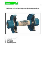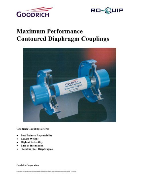
Maximum Performance Contoured Diaphragm ... - Ro-quip.com
Maximum Performance Contoured Diaphragm ... - Ro-quip.com
Maximum Performance Contoured Diaphragm ... - Ro-quip.com

You also want an ePaper? Increase the reach of your titles
YUMPU automatically turns print PDFs into web optimized ePapers that Google loves.
<strong>Maximum</strong> <strong>Performance</strong><br />
<strong>Contoured</strong> <strong>Diaphragm</strong> Couplings<br />
Goodrich Couplings offers:<br />
•<br />
•<br />
•<br />
•<br />
•<br />
Best Balance Repeatability<br />
Lowest Weight<br />
Highest Reliability<br />
Ease of Installation<br />
Stainless Steel <strong>Diaphragm</strong>s<br />
Goodrich Corporation<br />
C:\Documents and Settings\Tony\My Documents\Work\RO-QUIP\Principles\Goodrich_Lucas\Goodrich Brochure version 67U-6-978A, 5-27-03.doc
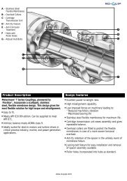
Goodrich <strong>Maximum</strong> <strong>Performance</strong> <strong>Contoured</strong> <strong>Diaphragm</strong> Couplings<br />
Proven Technology<br />
• 120,000 <strong>Diaphragm</strong> Couplings in Service.<br />
• 10 Million hour MTBF.<br />
Goodrich’ (The former Bendix Fluid Power<br />
Division) first patent of the contoured<br />
diaphragm coupling was in 1949 and after<br />
years of research and development the first<br />
diaphragm coupling was delivered for an<br />
aircraft application in 1955. This aerospace<br />
proven technology developed by Goodrich<br />
yielded the most reliable and lightweight<br />
approach to transferring torque and<br />
misalignment. In 1967 Goodrich supplied<br />
the first contoured diaphragm coupling for<br />
use in the industrial petrochemical market.<br />
Goodrich has supplied well over 120,000<br />
contoured diaphragm couplings over the past<br />
four decades. Over this time our reliability<br />
has been proven with a Mean Time between<br />
Failure (MTBF) of over 10 million operating<br />
hours. Goodrich is the World's Technology<br />
Leader for Power Transmission Couplings in<br />
the Industrial, Marine and Aerospace<br />
Markets. Goodrich has provided diaphragm<br />
couplings in the field from as small as 4<br />
inches in diameter too as large as 80 inches<br />
in diameter (See Figure 1).<br />
Goodrich Superior Design<br />
• Light weight/simple design.<br />
• Best balance capability.<br />
Goodrich Couplings have three major parts:<br />
a flex unit and two adapters (flange or hub)<br />
which interface with the driver and load<br />
machinery. This simple design only requires<br />
two joints and therefore has the best balance<br />
repeatability of any coupling. Competing<br />
designs require at least four joints and<br />
therefore the eccentricity between parts (5<br />
<strong>com</strong>pared to Goodrich’ 3) yields significant<br />
more imbalance when a unit is reassembled.<br />
The Goodrich flex unit has contoured<br />
diaphragms located at each end of the<br />
spacer and is joined by electron beam (EB)<br />
welding. The majority of Goodrich Couplings<br />
are supplied with EB Welded Flex units.<br />
Goodrich has never had a radial weld failure.<br />
Thorough NDT inspection is <strong>com</strong>pleted on<br />
each weld to ensure a quality seam.<br />
Each Goodrich flex unit is coated with<br />
multiple layers of Sermetel W, an<br />
inorganically (chemically) bonded aluminum<br />
coating, which offers a sacrificial method of<br />
corrosion protection. Any area of base<br />
material which be<strong>com</strong>es exposed to a hostile<br />
atmosphere is protected by Sermetel<br />
coating, which is more chemically reactive<br />
than steel, and will be the only surface to<br />
corrode. High temperature chemically<br />
resistant epoxy paint covers this coating.<br />
Goodrich leads the industry in sound<br />
engineering practice in designing our<br />
couplings. Some examples follow:<br />
• Hardware is shrouded to ensure low<br />
windage.<br />
• Helicoils are only used on special<br />
Designs.<br />
• Torque is not transmitted through our bolt<br />
threads.<br />
• No holes in flexure areas where bending<br />
takes place.<br />
• Wearing and fretting avoided – no loose or<br />
rubbing parts.<br />
Figure 1<br />
88E280 Marine <strong>Diaphragm</strong> Coupling<br />
(80 inches in diameter)<br />
That’s a <strong>Diaphragm</strong>!<br />
“The Proven Leader for<br />
<strong>Contoured</strong> <strong>Diaphragm</strong><br />
Couplings”<br />
Leading the State of The Art<br />
• Custom 455 Stainless Steel.<br />
• Patented <strong>Diaphragm</strong>.<br />
• New Low Moment.<br />
• API 610 Economic Design.<br />
Goodrich’s stainless steel diaphragm<br />
couplings (99/100 Series) have been in the<br />
field for over four years. This maximum<br />
performance design can't be matched by any<br />
other dry coupling of <strong>com</strong>parable size.<br />
Custom 455 stainless steel material has 30%<br />
greater strength than 15-5 PH material with<br />
similar corrosion protection properties.<br />
Goodrich Stainless Steel Couplings are, by<br />
far, the superior contoured diaphragm on the<br />
market.<br />
Goodrich continues to be on the leading<br />
edge of Coupling Technology. Our<br />
latest <strong>Diaphragm</strong> patent optimizes the<br />
diaphragm shape to yield the lowest<br />
stress for a given application torque and<br />
misalignment. Previous to this technology<br />
break through all diaphragm sizing was<br />
optimized only for torque using Wolff's<br />
conventional diaphragm design. Therefore<br />
Goodrich can provide the state of the art<br />
technology for a given set of conditions using<br />
either design.<br />
Goodrich's new low moment coupling uses<br />
our standard diaphragms welded to the<br />
backside of the hub eliminating the need to<br />
put the diaphragm on top of the hub. This<br />
design will be the future benchmark for<br />
having the lowest moment since the coupling<br />
half weight will be the lowest for a<br />
<strong>com</strong>parable bore size coupling and smallest<br />
centroid distance because of the flex<br />
element position. No other coupling<br />
manufacturer has our radial weld experience<br />
and therefore can not match this design.<br />
The customer is asked to verify that sufficient<br />
clearance between the bearing housing exist<br />
with the diaphragm. This design is ideal for<br />
those applications where lateral critical<br />
speeds are a concern.<br />
Presently Goodrich has a patent on our new<br />
API 610 & 671 <strong>Diaphragm</strong> Couplings, where<br />
we have developed a non welded joint for<br />
lower torque transmitting applications. This<br />
joint is still permanent with no additional<br />
hardware and therefore has the same<br />
balance repeatability of Goodrich standard<br />
design but is more <strong>com</strong>patible for mass<br />
production.<br />
C:\Documents and Settings\Tony\My Documents\Work\RO-QUIP\Principles\Goodrich_Lucas\Goodrich Brochure version 67U-6-978A, 5-27-03.doc
Design Philosophy<br />
• Analysis proved by test & FEA.<br />
The contoured diaphragm that Goodrich has originated and<br />
refined over the last half century has been proven time and<br />
again by field conditions as well as in house testing and<br />
analysis. Every aerospace coupling is subjected to 10<br />
million cycles in house at greater operating stresses than the<br />
unit will be subjected to in the field. FEA and strain gage<br />
testing have been <strong>com</strong>pleted for many different programs<br />
including the Frame 7E Mechanical Drive Load <strong>Diaphragm</strong><br />
Couplings. These methods have verified and validated<br />
Goodrich's proprietary <strong>com</strong>puter program for stress analysis<br />
and margin evaluation used for our aerospace, marine and<br />
industrial products resulting in the industry's highest<br />
reliability and lowest direct operating costs. This analysis<br />
incorporates the loading conditions as boundary values in<br />
exactly the same fashion as Finite Element Analysis (FEA).<br />
Goodrich uses multiple differential equations, which evaluate<br />
the diaphragm structure, and <strong>com</strong>pletes a numerical<br />
integration to develop the stresses in the diaphragm profile.<br />
Goodrich's <strong>com</strong>puter-based analysis has simplified our<br />
engineering effort such that it only takes seconds to<br />
determine the stress levels based on customer<br />
requirements. The proprietary <strong>com</strong>puter program sizes and<br />
<strong>com</strong>pletes a data sheet with all coupling characteristics in<br />
minutes such that the customer's quote has accurate<br />
engineering data provided. When ordering, this same data<br />
is generated into drawings, process and parts via our<br />
Computer Aided Design (CAD) and Computer Aided<br />
Manufacturing (CAM) Systems. Our new <strong>com</strong>puter system<br />
releases and tracks each order from entry to shipment<br />
ensuring an on time delivery.<br />
Coupling Ratings<br />
Goodrich <strong>Diaphragm</strong> Couplings have been rerated. Using<br />
the tables on page 3 and 5 for <strong>Maximum</strong> Continuous Torque<br />
and 125% misalignments (axial and angular) will yield a<br />
factor of safety of at least 1.25. Figure 2 shows a modified<br />
Goodman diagram for stainless steel (Custom 455). The<br />
<strong>com</strong>bined mean stress (steady state torque/axial & speed)<br />
and <strong>com</strong>bined alternating stress (bending & cyclic<br />
torque/axial) must have the plotted operating point fall within<br />
the area under the dotted line. Any point within this area has<br />
a minimum factor of safety of 1.25 using the proportional<br />
increase method.<br />
Special Feature<br />
L-Low Moment<br />
E-No Special Feature<br />
T-Torquemeter<br />
S-Shear Section<br />
B-Backup Gear<br />
R-Electrical Isolation<br />
M-Multiple <strong>Diaphragm</strong><br />
F-Flange End<br />
P-Non Welded Joint<br />
Identifies Flexible<br />
Coupling Model<br />
68 Non Welded Fitted Bolt Alloy Steel<br />
69 Non Welded Piloted Alloy Steel<br />
67/87 Welded Fitted Bolt Alloy Steel<br />
74/88 Welded Piloted Alloy Steel<br />
95/99 Welded Fitted Bolt Stainless Steel<br />
96/100 Welded Piloted Stainless Steel<br />
Goodrich Corporation Numbering System<br />
Type<br />
99 L 3 08 - 7777<br />
Nominal<br />
<strong>Diaphragm</strong><br />
Size (OD)<br />
<strong>Diaphragm</strong> Series<br />
300-1/3°<br />
400-1/4°<br />
500-1/5°<br />
600-1/6°<br />
Project/Job<br />
Number<br />
ksi<br />
Life Cycle Cost<br />
• Goodrich has lowest total system cost.<br />
Thanks to Goodrich's experience and technology, our<br />
<strong>Diaphragm</strong> Coupling is the most reliable coupling on the<br />
market. Because of Goodrich's infinite life design no spare<br />
parts (other than hardware) are required. Therefore the total<br />
system cost of the Goodrich coupling is significantly less<br />
than <strong>com</strong>peting designs where downtime to replace a flex<br />
element pack will result in added inventory and labor as well<br />
as interruption of production revenue.<br />
Materials<br />
Hub Flanges<br />
• Forging AISI 4340 or Equivalent<br />
• 130,000 PSI UTS Minimum<br />
<strong>Diaphragm</strong>s<br />
• Vacuum-Melted AMS 6414 Alloy Steel<br />
• 170,000 PSI UTS Minimum<br />
• Vacuum-Melted AMS 5617 Stainless Steel<br />
• 235,000 PSI UTS Minimum<br />
Guards<br />
• AISI 4140<br />
• 130,000 PSI UTS Minimum<br />
Tubes<br />
• AISI 4130, 4340, or Equivalent<br />
• 130,000 PSI UTS Minimum<br />
Shims<br />
• Low Carbon Steel, Nickel Plated or Stainless Steel<br />
Bolts<br />
• AISI 4140, 4340, 6150, 8740<br />
• Alloy Steel, Stainless Steel A286<br />
• 150,000-200,000 PSI UTS Minimum<br />
Nuts<br />
• Alloy Steel, Stainless Steel A286<br />
• 160,000 PSI UTS Minimum<br />
Protection<br />
• Sermetel<br />
• High Temperature Blue Paint<br />
100<br />
80<br />
60<br />
40<br />
20<br />
Modified Goodman Diagram<br />
for Stainless Steel AMS 5617<br />
100,000 PSI Fatigue Strength<br />
225,000 PSI Yield Strength<br />
Factor of Safety 1.25<br />
40 80 120 160 200 240<br />
Ksi<br />
Figure 2 Modified Goodman Diagram<br />
C:\Documents and Settings\Tony\My Documents\Work\RO-QUIP\Principles\Goodrich_Lucas\Goodrich Brochure version 67U-6-978A, 5-27-03.doc
Goodrich API 671 Standard & Reduced Moment Couplings<br />
High <strong>Performance</strong><br />
Alloy Steel<br />
87/88 Series<br />
<strong>Maximum</strong> <strong>Performance</strong><br />
Stainless Steel<br />
99/100 Series<br />
Type<br />
Size<br />
Max 1<br />
Continuou<br />
s Torque<br />
(in-lb)<br />
Axial 2<br />
Deflection<br />
(± in.)<br />
Max 1<br />
Continuo<br />
us Torque<br />
(in-lb)<br />
Axial 2<br />
Deflection<br />
(± inches)<br />
Misalignment<br />
per End<br />
(± Deg)<br />
Parallel 3<br />
Offset<br />
(in./in.)<br />
Limit<br />
Speed<br />
(RPM)<br />
Coupling 4<br />
OD<br />
A<br />
(inches)<br />
Max 5<br />
Taper<br />
Bore<br />
B<br />
(inches)<br />
305 19,000 0.055 29,000 0.049 0.333 0.0058 35,000 6.055 2.75<br />
405 26,000 0.044 38,000 0.040 0.250 0.0044 40,000 6.055<br />
505 32,000 0.039 48,000 0.032 0.200 0.0035 45,000 6.055 1.75<br />
605 38,000 0.034 58,000 0.026 0.167 0.0029 50,000 6.055<br />
306 38,000 0.058 57,000 0.060 0.333 0.0058 28,000 7.055 3.45<br />
406 51,000 0.053 76,000 0.047 0.250 0.0044 33,000 7.055<br />
506 63,000 0.046 95,000 0.040 0.200 0.0035 38,000 7.055 2.50<br />
606 75,000 0.032 114,000 0.033 0.167 0.0029 43,000 7.055<br />
308 83,000 0.082 127,000 0.075 0.333 0.0058 23,000 9.175 4.75<br />
408 113,000 0.070 169,000 0.063 0.250 0.0044 28,000 9.175<br />
508 141,000 0.061 212,000 0.051 0.200 0.0035 33,000 9.175 3.25<br />
608 170,000 0.054 245,000 0.047 0.167 0.0029 35,000 9.175<br />
310 158,000 0.101 238,000 0.086 0.333 0.0058 20,000 10.930 5.95<br />
410 211,000 0.087 317,000 0.072 0.250 0.0044 25,000 10.930<br />
510 264,000 0.076 397,000 0.058 0.200 0.0035 28,000 10.930 4.00<br />
610 316,000 0.067 477,000 0.050 0.167 0.0029 30,000 10.930<br />
312 289,000 0.118 435,000 0.105 0.333 0.0058 19.000 13.050 7.33<br />
412 386,000 0.104 580,000 0.087 0.250 0.0044 22,000 13.050<br />
512 482,000 0.091 725,000 0.073 0.200 0.0035 25,000 13.050 4.50<br />
612 580,000 0.080 870,000 0.062 0.167 0.0029 27,000 13.050<br />
314 429,000 0.128 646,000 0.115 0.333 0.0058 17,000 14.805 8.32<br />
414 572,000 0.115 861,000 0.097 0.250 0.0044 20,000 14.805<br />
514 715,000 0.101 1,076,000 0.081 0.200 0.0035 23,000 14.805 5.00<br />
614 855,000 0.090 1,293,000 0.068 0.167 0.0029 25,000 14,805<br />
316 682,000 0.136 1,029,000 0.126 0.333 0.0058 15,000 16.805 9.66<br />
416 910,000 0.126 1,373,000 0.107 0.250 0.0044 17,000 16.805<br />
516 1,138,000 0.112 1,715,000 0.090 0.200 0.0035 20,000 16.805 6.00<br />
616 1,365,000 0.100 2,059,000 0.076 0.167 0.0029 22,000 16.805<br />
318 925,000 0.162 1,390,000 0.148 0.333 0.0058 14,000 18.805 10.67<br />
418 1,234,000 0.148 1,854,000 0.125 0.250 0.0044 16,000 18.805<br />
518 1,543,000 0.131 2,317,000 0.106 0.200 0.0035 19,000 18.805 6.87<br />
618 1,851,000 0.116 2,781,000 0.091 0.167 0.0029 21,000 18.805<br />
322 1,763,000 0.211 2,651,000 0.172 0.333 0.0058 12,000 22.550 13.10<br />
422 2,352,000 0.196 3,535,000 0.148 0.250 0.0044 14,000 22.550<br />
522 2,938,000 0.154 4,418,000 0.128 0.200 0.0035 16,000 22.550 8.75<br />
622 3,525,000 0.137 5,301,000 0.108 0.167 0.0029 19,000 22.550<br />
1<br />
Peak torque is 133% of the maximum continuous torque. Couplings subjected to transient conditions should be<br />
evaluated using the Peak torque. Limit torque is 180% of the maximum continuous torque. Couplings subjected to a<br />
“one time” momentary load should be evaluated using the Limit torque.<br />
2<br />
Axial deflection is based on the maximum continuous torque listed. It is possible to trade off axial, torque and rated<br />
speed. Contact Goodrich Engineering for additional information.<br />
3<br />
Parallel offset equals the value shown multiplied by the distance between flexures.<br />
4<br />
Nominal dimension is for the piloted units (88 & 100 Series). Fitted bolt units (87 & 99 Series) are 0.360 inches less than<br />
tabulated value.<br />
5<br />
The maximum bore capacity shown are for tapered shaft ends. (Consult Page 5 for straight shaft ends). The first value<br />
for each size is for our standard couplings and the second is for our low moment couplings.<br />
C:\Documents and Settings\Tony\My Documents\Work\RO-QUIP\Principles\Goodrich_Lucas\Goodrich Brochure version 67U-6-978A, 5-27-03.doc
"A"<br />
"B"<br />
Figure 3 Standard Couplings<br />
"B"<br />
"A"<br />
Figure 4 Reduced Moment Couplings<br />
C:\Documents and Settings\Tony\My Documents\Work\RO-QUIP\Principles\Goodrich_Lucas\Goodrich Brochure version 67U-6-978A, 5-27-03.doc<br />
-4-
Selection Procedure<br />
Step 1 - Required Data<br />
<strong>Maximum</strong> Power ___ KW or<br />
HP<br />
Speed Range ___ RPM<br />
Trip Speed<br />
___ RPM<br />
Axial Movement<br />
Driver Machine ___Inch<br />
Load Machine ___Inch<br />
Parallel Offset ___Inch<br />
Angular Misalign ___Degrees<br />
Distance Between<br />
Shaft Ends (BSE) ___Inch<br />
Driver Shaft End<br />
Dia. (Straight or<br />
Taper)<br />
___Inch<br />
Load Shaft End<br />
Dia. (Straight or<br />
Taper)<br />
___Inch<br />
Envelope Minimum<br />
Diameter<br />
___Inch<br />
Special Requirements<br />
Torquemeter, Electric Isolation,<br />
Shear Section, Backup Gear Drive<br />
API 671 Required [ ] Yes [ ] No<br />
API 610 Required [ ] Yes [ ] No<br />
Step 2 - Torque Calculation<br />
Calculate the normal continuous<br />
torque.<br />
KW x 1.341 = HP<br />
T = ____(HP)_ (63,025)______ Lb-in<br />
Speed at which HP occurs<br />
For situations where the HP changes<br />
over the speed range, the condition<br />
generating the maximum continuous<br />
torque must be determined.<br />
Electric motor starts, generator short<br />
circuit, <strong>com</strong>pressor surge, and pump<br />
Cavitation cause single cycle peak<br />
torque requirements. This value may<br />
mandate a larger coupling selection,<br />
based upon the peak torque value of<br />
each coupling.<br />
Step 3 - Coupling Selection<br />
Select the coupling from page 3 or<br />
page 5, which has the maximum<br />
continuous torque greater than the<br />
calculated normal continuous torque<br />
with, specified application factor.<br />
Step 4 - Bore Capacity<br />
Verify the maximum bore capacity of the<br />
coupling selected is greater than the<br />
bores specified.<br />
Step 5 - Misalignments<br />
Verify that the coupling selected meets<br />
the angular and axial misalignments of<br />
the application.<br />
Step 6 - Contact Goodrich<br />
Goodrich will supply Coupling Selection<br />
Data Sheet in Imperial or SI units;<br />
including mass elastic, lateral and axial<br />
natural frequencies within 24 hours for<br />
standard designs!<br />
Retrofit Applications<br />
Goodrich <strong>Diaphragm</strong> Couplings are<br />
used frequently to replace gear, disc<br />
and other dry type couplings. Contact<br />
Goodrich with your Retrofit<br />
Requirements.<br />
Balance Standards<br />
Goodrich has standardized on a<br />
method of balance that eliminates the<br />
errors associated with arbor<br />
balancing:<br />
• Hubs are <strong>com</strong>ponent balanced on a<br />
vertical machine with bores indicated<br />
concentric to the rotating table. They<br />
are balanced in two planes. Balance<br />
journals are ground on the OD of<br />
hubs concentric to the hub bore.<br />
• The coupling is assembled with a<br />
prebalanced adapter installed within<br />
the hub bores. Concentricity of this<br />
adapter is maintained using spreader<br />
screws. Adjustment screws are<br />
used to stretch the diaphragms and<br />
rigidize the assembly.<br />
• Alignment involves rotating the<br />
coupling on its balance journals and<br />
indicating bore diameters. By<br />
adjusting adapter screws, hub bores<br />
are aligned to within 0.0002 T.I.R.<br />
Data recorded during alignment is<br />
used to <strong>com</strong>pute the eccentricity,<br />
which exists between the centerline<br />
of balance journals, and the actual<br />
centerline of the hub bore. This<br />
eccentricity is corrected for during<br />
the balance operation.<br />
Degree of Balance<br />
The ac<strong>com</strong>panying formula is used to<br />
calculate the balance tolerance per<br />
plane for any given coupling. The<br />
value of K assigned is usually<br />
dependent upon coupling application.<br />
The lower the value of K the tighter the<br />
balance tolerance.<br />
U = KW<br />
N<br />
U = Residual Unbalance per Plane<br />
(--In-Oz)<br />
W = Plane Weight (--Lb)<br />
N = Max Continuous Operating Speed<br />
(--RPM)<br />
K = Constant Denoting Degree of<br />
Balance<br />
Balance Repeatability<br />
The coupling assembly, with its<br />
fixtures, is balanced so that the<br />
unbalance (expressed as the distance<br />
between the coupling’s center of<br />
gravity and its center of rotation) is<br />
very small, generally less than<br />
0.000050 inches.<br />
However, even with the best of care<br />
small errors in the relative location of<br />
mating parts occur when the coupling is<br />
disassembled and then reassembled.<br />
These errors often add up to about<br />
0.000400 inch on our couplings.<br />
Thus, when a balanced coupling is<br />
checked for repeatability, unbalance<br />
values equivalent to U In-Oz = 0.0064 x<br />
W lbs. can be expected.<br />
To minimize these reassemble errors<br />
the Goodrich couplings:<br />
•<br />
•<br />
•<br />
•<br />
•<br />
•<br />
•<br />
•<br />
•<br />
Are lightweight.<br />
Have a minimum number of<br />
assembly joints.<br />
Are matchmarked for consistent<br />
assembly.<br />
Have all machining done before<br />
balancing.<br />
Have no surfaces, which wear.<br />
Are dimensionally stable.<br />
Have weight-matched bolts and<br />
nuts.<br />
Have zero clearance diametral<br />
locating pilots (Models 88 & 100).<br />
Have close-fitting locating bolts<br />
(Models 68, 87 & 99).<br />
C:\Documents and Settings\Tony\My Documents\Work\RO-QUIP\Principles\Goodrich_Lucas\Goodrich Brochure version 67U-6-978A, 5-27-03.doc
For Further Information Contact<br />
Goodrich Corporation<br />
Revised 3/03<br />
Pub 67U-6-978A<br />
ASIA-PACIFIC<br />
RO-QUIP Asia Pacific Pte Ltd<br />
Tel: +65 6736 0192<br />
Email: tony.martin@ro-<strong>quip</strong>.<strong>com</strong><br />
C:\Documents and Settings\Tony\My Documents\Work\RO-QUIP\Principles\Goodrich_Lucas\Goodrich Brochure version 67U-6-978A, 5-27-03.doc