Maximum Performance Contoured Diaphragm ... - Ro-quip.com
Maximum Performance Contoured Diaphragm ... - Ro-quip.com
Maximum Performance Contoured Diaphragm ... - Ro-quip.com

You also want an ePaper? Increase the reach of your titles
YUMPU automatically turns print PDFs into web optimized ePapers that Google loves.
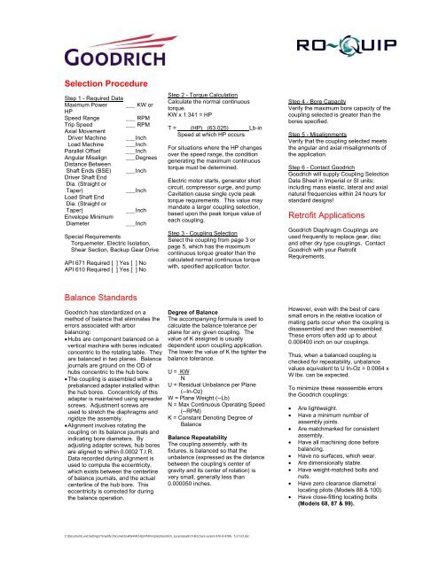
Selection Procedure<br />
Step 1 - Required Data<br />
<strong>Maximum</strong> Power ___ KW or<br />
HP<br />
Speed Range ___ RPM<br />
Trip Speed<br />
___ RPM<br />
Axial Movement<br />
Driver Machine ___Inch<br />
Load Machine ___Inch<br />
Parallel Offset ___Inch<br />
Angular Misalign ___Degrees<br />
Distance Between<br />
Shaft Ends (BSE) ___Inch<br />
Driver Shaft End<br />
Dia. (Straight or<br />
Taper)<br />
___Inch<br />
Load Shaft End<br />
Dia. (Straight or<br />
Taper)<br />
___Inch<br />
Envelope Minimum<br />
Diameter<br />
___Inch<br />
Special Requirements<br />
Torquemeter, Electric Isolation,<br />
Shear Section, Backup Gear Drive<br />
API 671 Required [ ] Yes [ ] No<br />
API 610 Required [ ] Yes [ ] No<br />
Step 2 - Torque Calculation<br />
Calculate the normal continuous<br />
torque.<br />
KW x 1.341 = HP<br />
T = ____(HP)_ (63,025)______ Lb-in<br />
Speed at which HP occurs<br />
For situations where the HP changes<br />
over the speed range, the condition<br />
generating the maximum continuous<br />
torque must be determined.<br />
Electric motor starts, generator short<br />
circuit, <strong>com</strong>pressor surge, and pump<br />
Cavitation cause single cycle peak<br />
torque requirements. This value may<br />
mandate a larger coupling selection,<br />
based upon the peak torque value of<br />
each coupling.<br />
Step 3 - Coupling Selection<br />
Select the coupling from page 3 or<br />
page 5, which has the maximum<br />
continuous torque greater than the<br />
calculated normal continuous torque<br />
with, specified application factor.<br />
Step 4 - Bore Capacity<br />
Verify the maximum bore capacity of the<br />
coupling selected is greater than the<br />
bores specified.<br />
Step 5 - Misalignments<br />
Verify that the coupling selected meets<br />
the angular and axial misalignments of<br />
the application.<br />
Step 6 - Contact Goodrich<br />
Goodrich will supply Coupling Selection<br />
Data Sheet in Imperial or SI units;<br />
including mass elastic, lateral and axial<br />
natural frequencies within 24 hours for<br />
standard designs!<br />
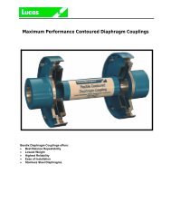
Retrofit Applications<br />
Goodrich <strong>Diaphragm</strong> Couplings are<br />
used frequently to replace gear, disc<br />
and other dry type couplings. Contact<br />
Goodrich with your Retrofit<br />
Requirements.<br />
Balance Standards<br />
Goodrich has standardized on a<br />
method of balance that eliminates the<br />
errors associated with arbor<br />
balancing:<br />
• Hubs are <strong>com</strong>ponent balanced on a<br />
vertical machine with bores indicated<br />
concentric to the rotating table. They<br />
are balanced in two planes. Balance<br />
journals are ground on the OD of<br />
hubs concentric to the hub bore.<br />
• The coupling is assembled with a<br />
prebalanced adapter installed within<br />
the hub bores. Concentricity of this<br />
adapter is maintained using spreader<br />
screws. Adjustment screws are<br />
used to stretch the diaphragms and<br />
rigidize the assembly.<br />
• Alignment involves rotating the<br />
coupling on its balance journals and<br />
indicating bore diameters. By<br />
adjusting adapter screws, hub bores<br />
are aligned to within 0.0002 T.I.R.<br />
Data recorded during alignment is<br />
used to <strong>com</strong>pute the eccentricity,<br />
which exists between the centerline<br />
of balance journals, and the actual<br />
centerline of the hub bore. This<br />
eccentricity is corrected for during<br />
the balance operation.<br />
Degree of Balance<br />
The ac<strong>com</strong>panying formula is used to<br />
calculate the balance tolerance per<br />
plane for any given coupling. The<br />
value of K assigned is usually<br />
dependent upon coupling application.<br />
The lower the value of K the tighter the<br />
balance tolerance.<br />
U = KW<br />
N<br />
U = Residual Unbalance per Plane<br />
(--In-Oz)<br />
W = Plane Weight (--Lb)<br />
N = Max Continuous Operating Speed<br />
(--RPM)<br />
K = Constant Denoting Degree of<br />
Balance<br />
Balance Repeatability<br />
The coupling assembly, with its<br />
fixtures, is balanced so that the<br />
unbalance (expressed as the distance<br />
between the coupling’s center of<br />
gravity and its center of rotation) is<br />
very small, generally less than<br />
0.000050 inches.<br />
However, even with the best of care<br />
small errors in the relative location of<br />
mating parts occur when the coupling is<br />
disassembled and then reassembled.<br />
These errors often add up to about<br />
0.000400 inch on our couplings.<br />
Thus, when a balanced coupling is<br />
checked for repeatability, unbalance<br />
values equivalent to U In-Oz = 0.0064 x<br />
W lbs. can be expected.<br />
To minimize these reassemble errors<br />
the Goodrich couplings:<br />
•<br />
•<br />
•<br />
•<br />
•<br />
•<br />
•<br />
•<br />
•<br />
Are lightweight.<br />
Have a minimum number of<br />
assembly joints.<br />
Are matchmarked for consistent<br />
assembly.<br />
Have all machining done before<br />
balancing.<br />
Have no surfaces, which wear.<br />
Are dimensionally stable.<br />
Have weight-matched bolts and<br />
nuts.<br />
Have zero clearance diametral<br />
locating pilots (Models 88 & 100).<br />
Have close-fitting locating bolts<br />
(Models 68, 87 & 99).<br />
C:\Documents and Settings\Tony\My Documents\Work\RO-QUIP\Principles\Goodrich_Lucas\Goodrich Brochure version 67U-6-978A, 5-27-03.doc