Maximum Performance Contoured Diaphragm ... - Ro-quip.com
Maximum Performance Contoured Diaphragm ... - Ro-quip.com
Maximum Performance Contoured Diaphragm ... - Ro-quip.com

Create successful ePaper yourself
Turn your PDF publications into a flip-book with our unique Google optimized e-Paper software.
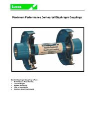
Design Philosophy<br />
• Analysis proved by test & FEA.<br />
The contoured diaphragm that Goodrich has originated and<br />
refined over the last half century has been proven time and<br />
again by field conditions as well as in house testing and<br />
analysis. Every aerospace coupling is subjected to 10<br />
million cycles in house at greater operating stresses than the<br />
unit will be subjected to in the field. FEA and strain gage<br />
testing have been <strong>com</strong>pleted for many different programs<br />
including the Frame 7E Mechanical Drive Load <strong>Diaphragm</strong><br />
Couplings. These methods have verified and validated<br />
Goodrich's proprietary <strong>com</strong>puter program for stress analysis<br />
and margin evaluation used for our aerospace, marine and<br />
industrial products resulting in the industry's highest<br />
reliability and lowest direct operating costs. This analysis<br />
incorporates the loading conditions as boundary values in<br />
exactly the same fashion as Finite Element Analysis (FEA).<br />
Goodrich uses multiple differential equations, which evaluate<br />
the diaphragm structure, and <strong>com</strong>pletes a numerical<br />
integration to develop the stresses in the diaphragm profile.<br />
Goodrich's <strong>com</strong>puter-based analysis has simplified our<br />
engineering effort such that it only takes seconds to<br />
determine the stress levels based on customer<br />
requirements. The proprietary <strong>com</strong>puter program sizes and<br />
<strong>com</strong>pletes a data sheet with all coupling characteristics in<br />
minutes such that the customer's quote has accurate<br />
engineering data provided. When ordering, this same data<br />
is generated into drawings, process and parts via our<br />
Computer Aided Design (CAD) and Computer Aided<br />
Manufacturing (CAM) Systems. Our new <strong>com</strong>puter system<br />
releases and tracks each order from entry to shipment<br />
ensuring an on time delivery.<br />
Coupling Ratings<br />
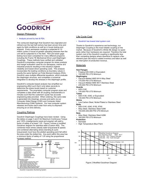
Goodrich <strong>Diaphragm</strong> Couplings have been rerated. Using<br />
the tables on page 3 and 5 for <strong>Maximum</strong> Continuous Torque<br />
and 125% misalignments (axial and angular) will yield a<br />
factor of safety of at least 1.25. Figure 2 shows a modified<br />
Goodman diagram for stainless steel (Custom 455). The<br />
<strong>com</strong>bined mean stress (steady state torque/axial & speed)<br />
and <strong>com</strong>bined alternating stress (bending & cyclic<br />
torque/axial) must have the plotted operating point fall within<br />
the area under the dotted line. Any point within this area has<br />
a minimum factor of safety of 1.25 using the proportional<br />
increase method.<br />
Special Feature<br />
L-Low Moment<br />
E-No Special Feature<br />
T-Torquemeter<br />
S-Shear Section<br />
B-Backup Gear<br />
R-Electrical Isolation<br />
M-Multiple <strong>Diaphragm</strong><br />
F-Flange End<br />
P-Non Welded Joint<br />
Identifies Flexible<br />
Coupling Model<br />
68 Non Welded Fitted Bolt Alloy Steel<br />
69 Non Welded Piloted Alloy Steel<br />
67/87 Welded Fitted Bolt Alloy Steel<br />
74/88 Welded Piloted Alloy Steel<br />
95/99 Welded Fitted Bolt Stainless Steel<br />
96/100 Welded Piloted Stainless Steel<br />
Goodrich Corporation Numbering System<br />
Type<br />
99 L 3 08 - 7777<br />
Nominal<br />
<strong>Diaphragm</strong><br />
Size (OD)<br />
<strong>Diaphragm</strong> Series<br />
300-1/3°<br />
400-1/4°<br />
500-1/5°<br />
600-1/6°<br />
Project/Job<br />
Number<br />
ksi<br />
Life Cycle Cost<br />
• Goodrich has lowest total system cost.<br />
Thanks to Goodrich's experience and technology, our<br />
<strong>Diaphragm</strong> Coupling is the most reliable coupling on the<br />
market. Because of Goodrich's infinite life design no spare<br />
parts (other than hardware) are required. Therefore the total<br />
system cost of the Goodrich coupling is significantly less<br />
than <strong>com</strong>peting designs where downtime to replace a flex<br />
element pack will result in added inventory and labor as well<br />
as interruption of production revenue.<br />
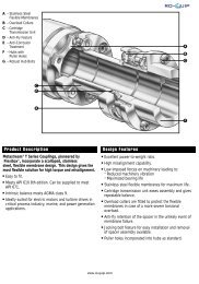
Materials<br />
Hub Flanges<br />
• Forging AISI 4340 or Equivalent<br />
• 130,000 PSI UTS Minimum<br />
<strong>Diaphragm</strong>s<br />
• Vacuum-Melted AMS 6414 Alloy Steel<br />
• 170,000 PSI UTS Minimum<br />
• Vacuum-Melted AMS 5617 Stainless Steel<br />
• 235,000 PSI UTS Minimum<br />
Guards<br />
• AISI 4140<br />
• 130,000 PSI UTS Minimum<br />
Tubes<br />
• AISI 4130, 4340, or Equivalent<br />
• 130,000 PSI UTS Minimum<br />
Shims<br />
• Low Carbon Steel, Nickel Plated or Stainless Steel<br />
Bolts<br />
• AISI 4140, 4340, 6150, 8740<br />
• Alloy Steel, Stainless Steel A286<br />
• 150,000-200,000 PSI UTS Minimum<br />
Nuts<br />
• Alloy Steel, Stainless Steel A286<br />
• 160,000 PSI UTS Minimum<br />
Protection<br />
• Sermetel<br />
• High Temperature Blue Paint<br />
100<br />
80<br />
60<br />
40<br />
20<br />
Modified Goodman Diagram<br />
for Stainless Steel AMS 5617<br />
100,000 PSI Fatigue Strength<br />
225,000 PSI Yield Strength<br />
Factor of Safety 1.25<br />
40 80 120 160 200 240<br />
Ksi<br />
Figure 2 Modified Goodman Diagram<br />
C:\Documents and Settings\Tony\My Documents\Work\RO-QUIP\Principles\Goodrich_Lucas\Goodrich Brochure version 67U-6-978A, 5-27-03.doc