DMX-Relaisinterface 2 DMX-Relaisinterface 2 SSR - DMX4ALL GmbH
DMX-Relaisinterface 2 DMX-Relaisinterface 2 SSR - DMX4ALL GmbH
DMX-Relaisinterface 2 DMX-Relaisinterface 2 SSR - DMX4ALL GmbH

Create successful ePaper yourself
Turn your PDF publications into a flip-book with our unique Google optimized e-Paper software.
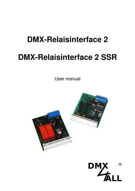
<strong>DMX</strong>-<strong>Relaisinterface</strong> 2<br />
<strong>DMX</strong>-<strong>Relaisinterface</strong> 2 <strong>SSR</strong><br />
User manual
<strong>DMX</strong>-Relais-Interface 2 2<br />
Specification<br />
The <strong>DMX</strong>-Relais-Interface 2 has 2 switching outputs which can be controlled by<br />
<strong>DMX</strong> in different operating modes.<br />
The following operating modes are available:<br />
- Standard 2 channel <strong>Relaisinterface</strong><br />
2 autonomous switching outputs will be activated as soon as the <strong>DMX</strong> value<br />
reaches the range 128-255.<br />
- FogControl<br />
2 switching outputs controlled by a <strong>DMX</strong>-channel. Thereby output 1 is for the<br />
heating element and output 2 for the pump control. An internal timer allows the<br />
automatic fog output.<br />
- Jalousie-Control<br />
2 mutual locked switching outputs, controlled by 2 <strong>DMX</strong>-channels. Thereby is<br />
only one relay switched on, if the <strong>DMX</strong> value reaches the range 128-255.<br />
RELAY 1<br />
<strong>DMX</strong><br />
<strong>DMX</strong><br />
INTERFACE<br />
RISC<br />
CONTROLLER<br />
RELAIS 2
<strong>DMX</strong>-Relais-Interface 2 3<br />
Technical data<br />
Voltage supply:<br />
12V DC / 250mA<br />
<strong>DMX</strong>-channels:<br />
1 or 2 channels, depending on operating mode<br />
Operating modes:<br />
Standard switching output<br />
Jalousie controlling<br />
FogControl<br />
Output:<br />
Standard Relais: 2 relay max. 8A / 250V~<br />
SolidState-Relais: 2 break contact max. 2A /250V~<br />
Board dimensions:<br />
64,2mm x 82mm<br />
LED-Display-Codes<br />
The integrated <strong>DMX</strong>-LED is used as a multifunctional display.<br />
This LED lights non-stop in normal operation. If the LED does not light, there is no<br />
<strong>DMX</strong>512-input-signal.<br />
Also the LED signalled the operation status. In this case the LED lights up in short<br />
pitches and then turns into off modus. The Number of flashing signals is equal to<br />
the Number of the error status.<br />
Error Error<br />
Description<br />
Status<br />
1 No <strong>DMX</strong> There is no <strong>DMX</strong>-input signal<br />
2 Address error Check if a valid <strong>DMX</strong>- starting address is<br />
adjusted at the DIP-switch<br />
3 <strong>DMX</strong> error An invalid <strong>DMX</strong> input signal is established
Connection<br />
<strong>DMX</strong>-Relais-Interface 2 4<br />
* = In the SolidState-Version not reserved<br />
Addressing<br />
The starting address is adjustable about the DIP-switch. Switch 1 has the valency 2 0<br />
(=1), switch 2 the valency 2 1 (=2) and so on … finally switch 9 has the valency 2 8<br />
(=256). The sum of the switches which are moved to ON position, represents the<br />
starting address.<br />
1<br />
2<br />
4<br />
8<br />
16<br />
32<br />
64<br />
128<br />
256<br />
-<br />
IN1<br />
IN1<br />
SCHLIEßER1<br />
Make Contact1<br />
ÖFFNER1*<br />
Break Contact 1<br />
IN2<br />
IN2<br />
Make<br />
SCHLIEßER2<br />
Contact 2<br />
Break ÖFFNER2* Contact 2<br />
-<br />
+12V +12V<br />
OV 0V (GND) (GND)<br />
<strong>DMX</strong> <strong>DMX</strong> + +<br />
<strong>DMX</strong>- <strong>DMX</strong> -<br />
<strong>DMX</strong> <strong>DMX</strong> GND GND<br />
<strong>DMX</strong><br />
IN<br />
POWER<br />
12V=<br />
<strong>DMX</strong><br />
OUT<br />
Address Switch<br />
Address Switch<br />
1 ... ...<br />
2 508<br />
3 509<br />
4 510<br />
5 511
<strong>DMX</strong>-Relais-Interface 2 5<br />
Selecting the operating mode<br />
• Standard 2 channel <strong>Relaisinterface</strong><br />
Open all Jumper J1-J5 for this operating mode<br />
<strong>DMX</strong><br />
Channel<br />
<strong>DMX</strong><br />
Value<br />
Function<br />
1<br />
2<br />
0-127 Output 1 OFF<br />
128-255 Output 1 ON<br />
0-127 Output 2 OFF<br />
128-255 Output 2 ON<br />
DIP-Switches 10 ON: With a missing <strong>DMX</strong>-Signal the relais will be switched on OFF.<br />
• FogControl<br />
Close only Jumper J1 for this operating mode<br />
<strong>DMX</strong><br />
Channel<br />
<strong>DMX</strong><br />
Value<br />
Function<br />
0-7 Device off<br />
8-20 Device on, no fog-emission<br />
21-40 Timer 10s on / 300s off *<br />
41-60 Timer 20s on / 350s off *<br />
61-80 Timer 30s on / 200s off *<br />
81-100 Timer 40s on / 150s off *<br />
1<br />
101-120 Timer 50s on / 100s off *<br />
121-140 Timer 60s on / 75s off *<br />
• Jalousie-Control<br />
Close only Jumper J2 for this operating mode<br />
141-160 Timer 70s on / 50s off *<br />
161-180 Timer 80s on / 40s off *<br />
181-200 Timer 90s on / 30s off *<br />
201-220 Timer 100s on / 20s off *<br />
221-240 Timer 110s on / 10s off *<br />
141-255 Permanent fog-emission<br />
<strong>DMX</strong><br />
Channel<br />
<strong>DMX</strong><br />
Value<br />
Function<br />
1<br />
2<br />
0-127 Output 1 OFF<br />
128-255 Output 1 ON, if Output 2 OFF<br />
0-127 Output 2 OFF<br />
128-255 Output 2 ON, if Output 1 OFF
<strong>DMX</strong>-Relais-Interface 2 6<br />
Equipment<br />
Housing for DIN-Rail-Mounting<br />
Top-hat rail housing 700<br />
Power Supply 12V / 20W
<strong>DMX</strong>-Relais-Interface 2 7<br />
CE-conformity<br />
This assembly (board) is controlled by a microprocessor and<br />
uses high frequency (8MHz). To get the characteristics of the<br />
assembly in relation to the CE-conformity, an installation in a<br />
compact metal casing is necessary.<br />
Risk-Notes<br />
You purchased a technical product. Conformable to the best available technology the<br />
following risks should not excluded:<br />
Failure risk: The device can drop out partially or completely at any time without<br />
warning. To reduce the probability of a failure a redundant system structure is<br />
necessary.<br />
Initiation risk: For the installation of the board, the board must be connected and<br />
adjusted to foreign components according to the device paperwork. This work can<br />
only be done by qualified personnel, which read the full device paperwork and<br />
understand it.<br />
Operating risk: The Change or the operation under special conditions of the<br />
installed systems/components could as well as hidden defects cause to breakdown<br />
within the running time.<br />
Misusage risk: Any nonstandard use could cause incalculable risks and is not<br />
allowed.<br />
Warning: It is not allowed to use the device in an operation, where the safety of<br />
persons depend on this device.
<strong>DMX</strong>4ALL <strong>GmbH</strong><br />
Reiterweg 2A<br />
D-44869 Bochum<br />
Germany<br />
© Copyright 2013 <strong>DMX</strong>4ALL <strong>GmbH</strong><br />
All rights reserve. No part of this manual may be reproduced in any form (photocopy, pressure, microfilm or in another<br />
procedure) without written permission or processed, multiplied or spread using electronic systems.<br />
All information contained in this manual was arranged with largest care and after best knowledge. Nevertheless errors are to be<br />
excluded not completely. For this reason I see myself compelled to point out that I can take over neither a warranty nor the<br />
legal responsibility or any adhesion for consequences, which decrease/go back to incorrect data. This document does not<br />
contain assured characteristics. The guidance and the characteristics can be changed at any time and without previous<br />
announcement.