STEPPER MOTOR CONTROLLER - AVRcard
STEPPER MOTOR CONTROLLER - AVRcard
STEPPER MOTOR CONTROLLER - AVRcard

You also want an ePaper? Increase the reach of your titles
YUMPU automatically turns print PDFs into web optimized ePapers that Google loves.
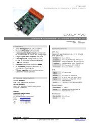
<strong>AVRcard</strong><br />
Building Blocks for Designers of Digital Products<br />
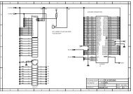
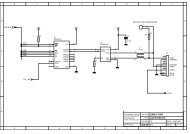
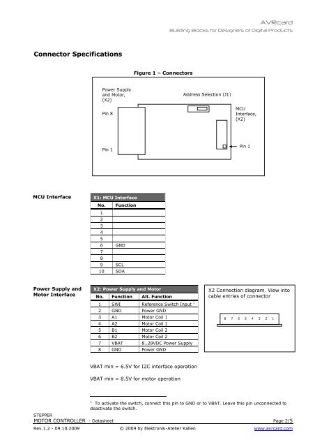
Connector Specifications<br />
Figure 1 – Connectors<br />
Power Supply<br />
and Motor,<br />
(X2)<br />
Address Selection (J1)<br />
Pin 8<br />
MCU<br />
Interface,<br />
(X2)<br />
Pin 1<br />
Pin 1<br />
MCU Interface<br />
X1: MCU Interface<br />
No. Function<br />
1<br />
2<br />
3<br />
4<br />
5<br />
6 GND<br />
7<br />
8<br />
9 SCL<br />
10 SDA<br />
Power Supply and<br />
Motor Interface<br />
X2: Power Supply and Motor<br />
No. Function Alt. Function<br />
1 SWI Reference Switch Input 1<br />
2 GND Power GND<br />
3 A1 Motor Coil 1<br />
4 A2 Motor Coil 1<br />
5 B1 Motor Coil 2<br />
6 B2 Motor Coil 2<br />
7 VBAT 8..29VDC Power Supply<br />
8 GND Power GND<br />
X2 Connection diagram. View into<br />
cable entries of connector<br />
8<br />
7<br />
6<br />
5<br />
4<br />
3<br />
2<br />
1<br />
VBAT min = 6.5V for I2C interface operation<br />
VBAT min = 8.5V for motor operation<br />
1 To activate the switch, connect this pin to GND or to VBAT. Leave this pin unconnected to<br />
deactivate the switch.<br />
<strong>STEPPER</strong><br />
<strong>MOTOR</strong> <strong>CONTROLLER</strong> - Datasheet Page 2/5<br />
Rev.1.2 - 09.10.2009 © 2009 by Elektronik-Atelier Kallen www.avrcard.com