3D Laser Scanning Multi Station Adjustment - Wilson Survey Group
3D Laser Scanning Multi Station Adjustment - Wilson Survey Group
3D Laser Scanning Multi Station Adjustment - Wilson Survey Group

Create successful ePaper yourself
Turn your PDF publications into a flip-book with our unique Google optimized e-Paper software.
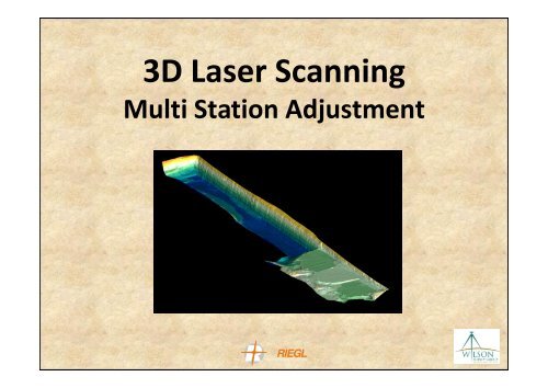
<strong>3D</strong> <strong>Laser</strong> <strong>Scanning</strong><br />
<strong>Multi</strong> <strong>Station</strong> <strong>Adjustment</strong>
Vehicle Mounted Riegl Z620<br />
The Scanner<br />
Long range terrestrial laser scanner<br />
Range of up to 2000m<br />
Full field of view – 360° x 80°<br />
Ability to acquire large quantities of point<br />
data in a short time<br />
The Vehicle<br />
Shock absorbing vehicle mount<br />
Mounted with Leica RTK GPS receivers<br />
Controlled from inside the vehicle<br />
Site compliant
Data Acquisition<br />
Method<br />
<strong>Multi</strong>ple Scan Positions<br />
Approximate 360° scan time of 6 minutes per scan<br />
Data Transferred to Laptop inside the vehicle via TCP/IP Cable<br />
RTK Observations on the scanner and backsight position<br />
Reduction using RiSCAN PRO <strong>Multi</strong> <strong>Station</strong> <strong>Adjustment</strong><br />
Vehicle Mount Advantages<br />
Removes the need for conventional tripod step-ups<br />
Reduces exposure to personal injury Eg. Slips, Trips, Falls<br />
Reduces interaction hazards between pedestrians and machinery during set-ups<br />
Increased time efficiency – More scans in less time!!!
<strong>Multi</strong> <strong>Station</strong> <strong>Adjustment</strong><br />
Used with most multiple scanning setups, “Static” or “Stop & Go” scanning<br />
Requires a minimum of 3 setups<br />
The better the geometry the more accurate the adjustment<br />
30% overlap or more is preferable<br />
Forms part of the “Registration” process<br />
Algorithm uses Plane & Point “Surface & Point Normals” to compute adjustment<br />
Like all good survey practices, checks are to be conducted for quality control
<strong>Multi</strong> <strong>Station</strong> <strong>Adjustment</strong><br />
Registration of multiple scans<br />
This is completed by acquiring a GPS positions for both the scanner and target while stationary<br />
These positions are used purely for the orientation of the scanner to the required co-ordinate system<br />
RiSCAN PRO “Backsight Orientation” registration<br />
RiSCAN PRO software uses a process called “Backsight Orientation” to register all the collected scans<br />
Plane Surface Filter<br />
This is the filter that creates a series of triangles which will<br />
overlap with each of the scans so that each of their “Normals”<br />
can be used in the process
<strong>Multi</strong> <strong>Station</strong> <strong>Adjustment</strong><br />
<strong>Multi</strong> <strong>Station</strong> <strong>Adjustment</strong> (MSA)<br />
The MSA is a very powerful tool and allows multiple scans to be selected similar to a Network<br />
<strong>Adjustment</strong> where all or some of the scans can be selected or used in order to get the other scans to<br />
be adjusted to each other or to just one scan<br />
We use the GPS scanner positions as fixed in X, Y & Z and allow the algorithm to adjust for Pitch, Roll,<br />
Yaw & Scale<br />
You will also be able to rotate the X, Y, Z view around in <strong>3D</strong> to visually make sure that the accuracy<br />
shown in the Histogram is covering the complete area and not just in one direction<br />
Once you are satisfied with results, compile a complete single pointcloud of all scans and drag in some<br />
check data, i.e. A GPS autorun to compare for any discrepancies
<strong>Multi</strong> <strong>Station</strong> <strong>Adjustment</strong>
Data Output<br />
On completion of the registration process, the data is run<br />
through a series of filters to remove isolated points like dust, any<br />
machines or foreign objects and nullify the redundant data.<br />
Some common output formats include:<br />
Point Cloud Eg. ‘.csv’ or ‘.asc’<br />
Point Grid<br />
Triangulation file Eg. ‘.obj’ or ‘.oot’<br />
The data can be further processed to include break lines or<br />
contours in a dxf format.
Checks and QA<br />
As with all survey work, checks are essential.<br />
Check #1<br />
<strong>Multi</strong>ple targets are placed throughout the area where they can be<br />
seen from various scan positions. The position of the targets are<br />
stored and compared with the ‘scanned’ coordinates in the post<br />
processed data. This process is used to check the heights and<br />
position of the scan data.<br />
Check #2<br />
Using RTK GPS, a series of QA shots are taken throughout the<br />
scanned area. These are compared with the post processed data<br />
and is used to check the heights of the scan data.
Mine Site Applications<br />
Pit <strong>Survey</strong>s<br />
Quantity <strong>Survey</strong>s<br />
Dump <strong>Survey</strong>s<br />
Stockpiles (Coal, Topsoil, Gravel, etc)<br />
Pre Blast and Post Blast <strong>Survey</strong>s<br />
High-wall Deformation<br />
Tailings Dams<br />
Accident Investigation
Pit Scan Example<br />
Open Cut Pit<br />
• Pit Dimensions – 800m x 1000m<br />
• 18 Scans<br />
• 4 Hours <strong>Scanning</strong><br />
• 2 Hours Reduction<br />
Scan Positions
Coal Stockpile Scan Example<br />
ROM Stockpiles<br />
• Stockpile Dimensions – 500m x 300m<br />
• 16 Scans<br />
• 3 Hours <strong>Scanning</strong><br />
• 2 Hours Reduction<br />
Scan Positions
Coal Stockpile Scan Example<br />
Product Stockpiles<br />
• 12 Scans<br />
• 3 Hours <strong>Scanning</strong><br />
• 2 Hours Reduction