Clock and Data Recovery Circuit Using Digital Phase Aligner and ...
Clock and Data Recovery Circuit Using Digital Phase Aligner and ...
Clock and Data Recovery Circuit Using Digital Phase Aligner and ...

You also want an ePaper? Increase the reach of your titles
YUMPU automatically turns print PDFs into web optimized ePapers that Google loves.
<strong>Clock</strong> <strong>and</strong> <strong>Data</strong> <strong>Recovery</strong> <strong>Circuit</strong> <strong>Using</strong> <strong>Digital</strong> <strong>Phase</strong><br />
<strong>Aligner</strong> <strong>and</strong> <strong>Phase</strong> Interpolator<br />
Seung-Woo Lee1), Chang-Kyung Seong2), Woo-Young Choi2) <strong>and</strong> Bhum-Cheol Lee')<br />
1) Switching Technology Team<br />
Electronics <strong>and</strong> Telecommunications Research Institute<br />
Daejon, Korea<br />
beewoo@etri.re.kr<br />
Abstract <strong>Clock</strong> <strong>and</strong> data recovery circuit using digital phase<br />
aligner <strong>and</strong> phase interpolator is proposed for multi-channel<br />
link applications. The proposed circuit reduces recovered clock<br />
jitter <strong>and</strong> alleviates the problem of distorted clock duty cycle.<br />
It is realized in 0.13um CMOS technology. Its power<br />
dissipation is 9.7mW at 1.2V power supply <strong>and</strong> its occupation<br />
area is 290x230um2 with multi-phase clock generation block.<br />
The experimental results show that the proposed circuit<br />
recovers lGb/s of 27-1 PRBS with no error.<br />
I. INTRODUCTION<br />
In broadb<strong>and</strong> network, the dem<strong>and</strong>s for wide b<strong>and</strong>width<br />
of upstream <strong>and</strong> downstream in switch applications increase<br />
<strong>and</strong> many high speed I/O interfaces are integrated in switch<br />
chips. In order to reduce the number of I/O pins, the interface<br />
between physical links <strong>and</strong> switch moves toward high speed<br />
serial interface. Also, the needs for the clock <strong>and</strong> data<br />
recovery circuits with low power <strong>and</strong> small area grow<br />
mcreasmgly.<br />
In general, clock <strong>and</strong> data recovery using phase-locked<br />
loop[l] includes analog loop filter with large area <strong>and</strong><br />
voltage-controlled oscillator with high noise sensitivity. To<br />
establish multi-channel 11O interfaces, many phase-locked<br />
loops which are largely occupied with loop filter are required.<br />
Another design approach is also available using digital logic<br />
immune to noise sensitivity. Oversampling scheme[2]<br />
detects data edge using oversampled clocks <strong>and</strong> picks the<br />
correct data using majority-voting. Its main disadvantages<br />
are more power dissipation <strong>and</strong> increased algorithm<br />
complexity.<br />
In [3] <strong>and</strong> [4], clock <strong>and</strong> data recovery with digital phase<br />
aligner (DPA) is introduced to have all digital structure,<br />
which is less sensitive to PVT variations <strong>and</strong> is simply<br />
designed by using st<strong>and</strong>ard cell logic. However, it has some<br />
problems as following. The clock <strong>and</strong> data recovery using<br />
DPA has no ability to reject jitters of incoming data so that<br />
the recovered clock has the same amount of jitters in input<br />
data. In addition, it synthesizes selected clocks to deteriorate<br />
duty cycle of recovered clock. Therefore, it is difficult to<br />
2) Dept. of Electronic Engineering<br />
Yonsei University<br />
Seoul, Korea<br />
ck(tera.yonsei.ac.kr<br />
design elastic buffer to have good timing margin for system<br />
clock.<br />
In this paper, the clock <strong>and</strong> data recovery using DPA <strong>and</strong><br />
phase interpolator is proposed to reduce jitters of recovered<br />
clock <strong>and</strong> alleviate distorted duty cycle. In section II, we<br />
represent the features of overall architecture <strong>and</strong> describe the<br />
operation of each block. Section III shows the experimental<br />
results of the chip performance. Finally, it is summarized<br />
with conclusions in section IV.<br />
II. OVERALL ARCHITECTURE<br />
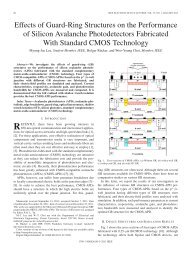
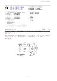
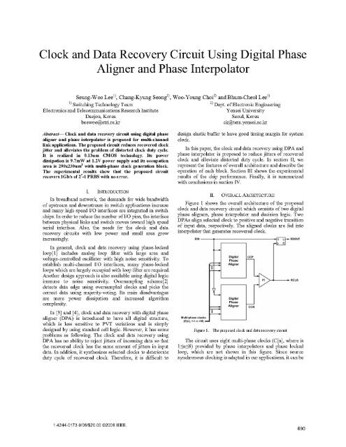
Figure 1 shows the overall architecture of the proposed<br />
clock <strong>and</strong> data recovery circuit which consists of two digital<br />
phase aligners, phase interpolator <strong>and</strong> decision logic. Two<br />
DPAs align selected clock to positive <strong>and</strong> negative transition<br />
of input data, respectively. The aligned clocks are fed into<br />
interpolator that generates recovered clock.<br />
DIN<br />
Multiphasa clocks[<br />
(Cin,1(n!9N)<br />
Figure 1.<br />
<strong>Digital</strong>J<br />
<strong>Phase</strong><br />
<strong>Aligner</strong><br />
Digitl,<br />
<strong>Phase</strong><br />
<strong>Aligner</strong><br />
cP<br />
CCN<br />
The proposed clock <strong>and</strong> data recovery circuit<br />
P<br />
RDOUT<br />
RCLK<br />
The circuit uses eight multi-phase clocks (C[n], where is<br />
l
assumed that multi-phase clocks are frequency-locked to the<br />
incoming data.<br />
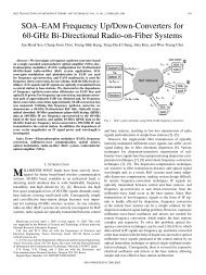
A. <strong>Digital</strong> <strong>Phase</strong> <strong>Aligner</strong><br />
In figure 2, DPA consists of multi-phase comparator <strong>and</strong><br />
phase selector, which include flip-flops <strong>and</strong> OR logic. It<br />
corresponds to the upper DPA of overall circuit in figure 1.<br />
The multi-phase comparator compares multi-phase clocks at<br />
the data transition time <strong>and</strong> provides select signals to phase<br />
selector, in which the optimum clock of multi-phase clocks<br />
is selected <strong>and</strong> the composed clock of CCP is generated.<br />
When transition of the input data occurs, the first column of<br />
flip-flops (FF1) in phase comparator samples multi-phase<br />
clocks of C[n] at the rising time of DIN <strong>and</strong> holds the<br />
latched value of C[n] until the next rising time of DIN. The<br />
second column of flip-flops (FF2) in phase comparator<br />
samples the latched value of C[n] at the falling time of DIN.<br />
The circuit compares the outputs of FF2 with multi-phase<br />
clocks <strong>and</strong> generates the select signal of SP[n]. Two<br />
consecutive flip-flops are used in order to prevent<br />
malfunction when meta-stability condition occurs. Figure 3<br />
shows the timing diagram of DPA. For example, if C[n-1]<br />
<strong>and</strong> C[n] are respectively '1' <strong>and</strong> '0' at the rising time of<br />
DIN, the select signal of SP[n] changes '1' to '0' at the<br />
falling time of DIN, which means that C[n] is chosen as the<br />
optimum clock closer to the center of data bit. It is<br />
represented as SP[k] in figure 3 that the kth select signal<br />
remains '0' <strong>and</strong> others are '1' until before the state of select<br />
signal changes.<br />
Multi-<strong>Phase</strong> Crrparator<br />
<strong>Phase</strong> Selector<br />
input merges the GCP[n]s to provide CCP for positive input<br />
data transition.<br />
Q!nc(n.1<br />
)<br />
I<br />
Figure 3.<br />
A timing diagram ofDPA<br />
B. <strong>Phase</strong> Interpolator<br />
As shown in figure 1, there are two DPAs for positive<br />
<strong>and</strong> negative transition of DIN in the proposed circuit. The<br />
optimum sampling clock for the positive transition of DIN<br />
is driven from the upper DPA. On the other side, the<br />
optimum sampling clock for negative transition of DIN<br />
comes from the lower one. The phase interpolator takes two<br />
inputs from two DPAs <strong>and</strong> mixes them to produce the<br />
output of the phase positioned between their phases. In Fig.<br />
1. CCP from positive digital phase aligner <strong>and</strong> CCN from<br />
negative one are fed into the phase interpolator to be<br />
interpolated. When the data with jitter is inputted into the<br />
circuit, the phase of the sampling clock from the positive<br />
digital phase aligner can be different from the one of the<br />
negative digital phase aligner.<br />
C(1 )<br />
DIN<br />
C(7) +-<br />
&<br />
P<br />
4]<br />
DN<br />
C(8)<br />
SNh M2t .......*~ 2<br />
Figure 2.<br />
Multi-phase comparator <strong>and</strong> phase selector<br />
In phase selector, the gated clock of GCP[n] is activated<br />
using multi-phase clocks <strong>and</strong> SP[n] from the phase<br />
comparator. The circuit merges the gated clocks into the<br />
optimum sampling clock of CCP for the positive transition<br />
of input data. When SP[n] is '0', which means that C[n] is<br />
selectable as the optimum clock for data bit, C[n] of multiphase<br />
clocks is selected by OR logic <strong>and</strong> GCP[n] is<br />
synchronized to C[n]. When SP[n] is '1', which means that<br />
C[n] is not useful for sampling the input data, C[n] is not<br />
selected <strong>and</strong> GCP[n] remains '1'. The OR logic with N<br />
ilutae in figr 4, whe tejtrocusidaa bit the<br />
trnition4<br />
AtimeiofdiNgrashriftsebyethewiamonundtaofincomin<br />
jitter <strong>and</strong> it results in the phase difference of two merged<br />
691
clocks of CCP <strong>and</strong> CCN. The interpolator averages them to<br />
reduce the jitter of the retiming clocks. In figure 4, SN[n]<br />
<strong>and</strong> CCN denote the select signal <strong>and</strong> the composed clock of<br />
the lower DPA, respectively.<br />
In order to evaluate the jitter performance, the<br />
conventional circuit of [4] <strong>and</strong> the proposed one are<br />
modeled with behavioral simulation described in [5]. The<br />
conventional circuit samples multi-phase clocks at rising<br />
edge of data but our circuit does at both of rising <strong>and</strong> falling<br />
edges. Input data with 3/8 UIp-p (peak-to-peak unit interval)<br />
of eye closing <strong>and</strong> uniformly distributed jitter is applied <strong>and</strong><br />
output jitters of recovered clock are compared as shown in<br />
figure 5. In this figure, the phase variations of input data <strong>and</strong><br />
recovered clock are represented as unit interval (UI).<br />
Simulation results show that peak-to-peak jitters of both<br />
circuits are similar to about 0.4 UI because the peak-to-peak<br />
jitter is limited by quantized resolution of clock phases.<br />
However, rms jitter of the proposed circuit is decreased by<br />
30%. The proposed clock <strong>and</strong> data recovery can filter the<br />
input jitter using the phase interpolator, whereas the<br />
conventional circuit has no ability to reject the input jitter. It<br />
can also alleviate degradation of duty cycle of recovered<br />
clock resulted from abrupt changes of clock phases.<br />
Therefore, it overcomes the problem that is difficult to<br />
design elastic buffer with sufficient timing margin.<br />
III. EXPERIMENTAL RESULTS<br />
The proposed clock <strong>and</strong> data recovery circuit is<br />
fabricated by 0.13um 1 -poly, 8-metal n-well CMOS process<br />
technology. It is designed to operate at 1Gb/s data rate <strong>and</strong><br />
have 9.7mW of power dissipation with 1.2V of power<br />
supply. DPA <strong>and</strong> phase interpolator consumes only 3mW.<br />
Figure 6 shows the circuit layout <strong>and</strong> its occupation of<br />
290um x 230um including multi-phase clock generator bock.<br />
In our realization, DPA is designed with single logic for low<br />
power dissipation <strong>and</strong> phase interpolator with differential<br />
circuit for noise immunity. Therefore, single-to-differential<br />
<strong>and</strong> differential-to-single circuits are used for logic<br />
conversion. The dummy logic cell is also included for<br />
matching delay between input data <strong>and</strong> recovered clock.<br />
'<br />
m~~~~~~~b<br />
Figure5. Comparison ofjitter performancewhen input data jitter occurs:<br />
(a) input data jitter (b) the conventional circuit <strong>and</strong> (c) the poposed circuit<br />
Figure 6.<br />
The layout of the poposed circuit<br />
A PLL was designed to have second-order loop filters to<br />
make the loop b<strong>and</strong>width 1/100 of the external frequency. It<br />
occupies 120um x 250um without loop filters <strong>and</strong> provides<br />
4 phase clocks to the proposed circuit, which generates<br />
equally spaced 8 phase clocks from multi-phase clock<br />
generator. Figure 7 shows measured jitter histogram of<br />
1 GHz PLL output clock. As shown in the figure, rms <strong>and</strong><br />
peak-to-peak jitter of the PLL output clock are 5.9ps<br />
(0.006UI) <strong>and</strong> 34.4ps (0.034UI), respectively.<br />
In figure 8, it shows the measured eye diagram for the<br />
recovered data of the proposed circuit. The width <strong>and</strong> height<br />
of opening eye are 780ps (0.78UI) <strong>and</strong> 300mV, respectively.<br />
For measurement, 1Gb/s of 2 -1 PRBS was applied to result<br />
in operating no error.<br />
692
educe the jitter of recovered clock <strong>and</strong> alleviate the problem<br />
of distorted duty cycle. Since it has low power of 9.7mW <strong>and</strong><br />
small area per channel to recover data, it is suitable for multilink<br />
applications. It is immune to PVT variation <strong>and</strong> operates<br />
in a stable manner due to digital logic <strong>and</strong> phase interpolator.<br />
Its experimental result shows that it operates at 1Gb/s of 27-1<br />
PRBS with no error.<br />
Figure 7.<br />
Jitter histogram of PLL ouptut<br />
REFERENCES<br />
[1] H. Djahanshahi <strong>and</strong> C.A.T. Salama, "Differential CMOS circuits for<br />
622-MHz/933-MHz clock <strong>and</strong> data recovery applications," IEEE J.<br />
Solid-State <strong>Circuit</strong>s, vol. 35, pp. 847-855, June 2000.<br />
[2] C.-K. Yang <strong>and</strong> M. Horowitz, "A 0.8um CMOS 2.5Gb/s<br />
oversampling receiver <strong>and</strong> tramsmitter for serial links," IEEE J.<br />
Solid-State <strong>Circuit</strong>s, vol. 31, pp. 2015-2023, December 1996.<br />
[3] R.R.Cordell, "A 45-Mbit/s CMOS VLSI digital phase aligner," IEEE<br />
J. Solid-State <strong>Circuit</strong>s, vol. 23, pp. 323-328, April 1998.<br />
[4] H.Y. Jung, B.C. Lee, <strong>and</strong> K.C. Park, "High speed digital<br />
retiming apparatus," U.S. Patent 5887040, March 23, 1999.<br />
data<br />
[5] M.H. Perrott, "Fast <strong>and</strong> accurate behavioral simulation of fractional-<br />
N frequency synthesizers <strong>and</strong> other PLL/DLL circuits," Design<br />
Automation Conference 2002, Proceedings 39th, pp. 498-503, June<br />
2002.<br />
Figure 8. Output eye diagram at 1 (b/s<br />
The summary of the circuit performance is shown in<br />
table 1.<br />
TABLE I.<br />
Parameter<br />
Process Technology<br />
Supply Voltage<br />
Layout Size<br />
Power Dissipation<br />
PLL output jitter<br />
Bit Error Ratio<br />
SUMMARY OF THE CIRCUIT PERFORMANCE<br />
Value<br />
0.13um 1-poly 8-metal CMOS<br />
+1.2V single supply<br />
290x230um2 including multi-phase clock<br />
generation block<br />
9.7mW @ 1Gb/s<br />
rms jitter: 5.9 ps<br />
p-p jitter: 34.4 ps<br />
No error with 27_1 PRBS at 1Gb/s<br />
IV. CONCLUSION<br />
<strong>Clock</strong> <strong>and</strong> data recovery to operate at 1Gb/s is proposed<br />
<strong>and</strong> fabricated with 0. 13um CMOS process. This circuit<br />
includes digital phase aligner <strong>and</strong> phase interpolator to<br />
693