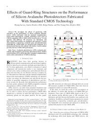
A 40-Gb/s Clock and Data Recovery Circuit in 0.18-um CMOS ...
A 40-Gb/s Clock and Data Recovery Circuit in 0.18-um CMOS ...
A 40-Gb/s Clock and Data Recovery Circuit in 0.18-um CMOS ...

You also want an ePaper? Increase the reach of your titles
YUMPU automatically turns print PDFs into web optimized ePapers that Google loves.
A <strong>40</strong>-<strong>Gb</strong>/s <strong>Clock</strong> <strong>and</strong> <strong>Data</strong> <strong>Recovery</strong><strong>Circuit</strong> <strong>in</strong> <strong>0.18</strong>-<strong>um</strong> <strong>CMOS</strong> TechnologyJri Lee, Student Member ,IEEE, <strong>and</strong> Behzad Razavi, Fellow, IEEEIEEE Jorunal of Solid State <strong>Circuit</strong>s, VOL. 38, NO. 12, DECEMBER 2003Dae-hyun Kwon
Contents <strong>Clock</strong> <strong>and</strong> <strong>Data</strong> <strong>Recovery</strong> circuits– Why quarter-rate?– CDR build<strong>in</strong>g blocks Sampler Xor V/I converter VCO– Non-ideal Effect Staggered Outputs Group velocity– Results– Conclusion
<strong>Clock</strong> <strong>and</strong> <strong>Data</strong> <strong>Recovery</strong> <strong>Circuit</strong>s Why quarter-rate CDR?– The limitation of fabrication <strong>0.18</strong>-<strong>um</strong> fT=50[GHz] Ga<strong>in</strong> X BW =constant, Ga<strong>in</strong>=1 BW=? Fanout one 12 <strong>Gb</strong>/s220SEC 65nm200Transit Frequency [GHz]1801601<strong>40</strong>1201008060<strong>40</strong>Freescale SOI 130nmTSMC 180nmSEC 130nmTSMC 65nmTSMC 90nm180 160 1<strong>40</strong> 120 100 80 60Technology [nm]
<strong>Clock</strong> <strong>and</strong> <strong>Data</strong> <strong>Recovery</strong> <strong>Circuit</strong>s Why quarter-rate CDR?– Half –rate CDR Latch X 4 (necessary <strong>in</strong>ductor X 8)– The speed limitation of frequency divider– Lots of FF(Flip-Flop) for mak<strong>in</strong>g full or half-rate CDR
<strong>Clock</strong> <strong>and</strong> <strong>Data</strong> <strong>Recovery</strong> Build<strong>in</strong>g Blocks Sampler Design– Conventional type of Flip-Flop Voltage headroom speed limitation <strong>Data</strong> can affect to the output without isolation– Inductive peak<strong>in</strong>g type Bulky
<strong>Clock</strong> <strong>and</strong> <strong>Data</strong> <strong>Recovery</strong> Build<strong>in</strong>g Blocks Modified Flip-FlopConventional typeInductive peak<strong>in</strong>gModified FF– Isolation <strong>in</strong>put <strong>and</strong> output <strong>Clock</strong> feed-through– Solv<strong>in</strong>g problem of voltage headroom– Without <strong>in</strong>ductor small area– Systematic delay mismatch Buffer<strong>in</strong>g with Cherry-Hopper Amp.
<strong>Clock</strong> <strong>and</strong> <strong>Data</strong> <strong>Recovery</strong> Build<strong>in</strong>g Blocks Xor– Conventional type voltage headroom <strong>and</strong> speed limitation– Other types of Xor is used– Controll<strong>in</strong>g the V GS , Xor can be operated
<strong>Clock</strong> <strong>and</strong> <strong>Data</strong> <strong>Recovery</strong> Build<strong>in</strong>g Blocks V to I converter– Not switch every phase comparison Free from dead-zone Dead-zone cause of Charge p<strong>um</strong>p (Every phase switch<strong>in</strong>g for current flow<strong>in</strong>g) Dead-zoneBang-bang PD ga<strong>in</strong>I<strong>Data</strong><strong>Data</strong><strong>Clock</strong>Dead-zoneΔɸupdownCK0 CK45 CK90HighupLowHighdownLow
<strong>Clock</strong> <strong>and</strong> <strong>Data</strong> <strong>Recovery</strong> Build<strong>in</strong>g Blocks Voltage controlled Oscillator– LC oscillator Lower phase noise & larger voltage sw<strong>in</strong>g
<strong>Clock</strong> <strong>and</strong> <strong>Data</strong> <strong>Recovery</strong> Build<strong>in</strong>g Blocks Phase Detector– Bang-bang PD– Sampler X 8 + Xor X 8 quarter-rate clock sampl<strong>in</strong>g
Non-ideal Effects Staggered OutputsDQ0 45 90 1350 45 90 135No data transitionCK0D QCK45X1X2I1DQVCODCK90QX3I2X1CK135X4X2X3I1I2– Low pass filter extract value of the V/I output– Misalignment creates ripple on the oscillator control Voltage– Kvco = 1GHz / VVcont87.5 ps
Non-ideal Effects Group Velocity– Limited BW of CDR reject jitter– <strong>Data</strong> duty cycle + Multiphase clock align– Without <strong>in</strong>ductor <strong>and</strong> compact layout for decreas<strong>in</strong>g length between <strong>in</strong>put Flip-Flop
Results Test set-up & Experimental results– PRBS 2 31 -1– BER = 10 -6– RMS jitter =0.9 [psec]– Power dissipation = 144 [mW]
Results
Conclusion <strong>0.18</strong> – <strong>um</strong> <strong>CMOS</strong> technology be<strong>in</strong>g used for <strong>40</strong>-<strong>Gb</strong>/s CDR Without <strong>in</strong>ductors, Flip-Flop could sample the <strong>40</strong>-<strong>Gb</strong>/s data with 10GHzclock Decreas<strong>in</strong>g dead-zone by us<strong>in</strong>g V to I converter Decreas<strong>in</strong>g phase noise by mak<strong>in</strong>g VCO with LC, passive components
Thank you for listen<strong>in</strong>g!