2012 super duty f-series incomplete vehicle manual - Ford Fleet
2012 super duty f-series incomplete vehicle manual - Ford Fleet
2012 super duty f-series incomplete vehicle manual - Ford Fleet

You also want an ePaper? Increase the reach of your titles
YUMPU automatically turns print PDFs into web optimized ePapers that Google loves.
DO NOT DESTROY: THIS MANUAL IS REQUIRED BY<br />
LAW. KEEP UNTIL THE VEHICLE IS COMPLETED BY<br />
THE FINAL STAGE MANUFACTURER.<br />
<strong>2012</strong><br />
SUPER DUTY F-SERIES<br />
INCOMPLETE VEHICLE MANUAL<br />
Incomplete Vehicle Types<br />
For This Manual<br />
Super Duty F-Series<br />
Chassis Cab<br />
February, 2011<br />
CC34-19A268-AA
U.S. & CANADIAN MOTOR VEHICLE SAFETY STANDARDS<br />
(Application By Vehicle Type)<br />
Vehicle Type<br />
Standard Equipment<br />
Number Title of Standard Truck MPV (1)<br />
101 Controls and Displays X X<br />
102 Transmission Shift Lever Sequence, Starter Interlock, and Transmission Braking Effect X X<br />
103 Windshield Defrosting and Defogging Systems X X<br />
104 Windshield Wiping and Washing Systems X X<br />
105 Hydraulic and Electric Brake Systems X X<br />
106 Brake Hoses X X X<br />
108 Lamps, Reflective Devices, and Associated Equipment X X X<br />
108.1 Headlamps (Canada only) X X X<br />
110 Tire Selection and Rims for Motor Vehicles with a GVWR of<br />
4,536 kilograms (10,000 pounds) or less (U.S. only) X(2) X(2) X(2)<br />
111 Rearview Mirrors X X<br />
113 Hood Latch System X X<br />
114 Theft Protection and Rollaway Prevention X(2) X(2)<br />
115 Vehicle Identification Number (Canada only) X X<br />
116 Motor Vehicle Brake Fluids X X X<br />
118 Power-Operated Window, Partition, and Roof Panel Systems X(2) X(2)<br />
119 (7) New Pneumatic Tires for Motor Vehicles with a GVWR of more than 4,536 kilograms (10,000 pounds) X(8)<br />
120 Tire Selection and Rims for Motor Vehicles with a GVWR of more than 4,536 kilograms (10,000 pounds) X(8) X(8) X(8)<br />
124 Accelerator Control Systems X X<br />
126 Electronic Stability Control Systems X (2) X(2) X(2)<br />
138 Tire Pressure Monitoring Systems X(2) X(2) X(2)<br />
139 New Pneumatic Radial Tires for Light Vehicles X(2)<br />
201 Occupant Protection in Interior Impact X(2) X(2)<br />
202a Head Restraints X(2) X(2)<br />
203 Impact Protection for the Driver from the Steering Control System X(2) X(2)<br />
204 Steering Control Rearward Displacement X(3) X(3)<br />
205 Glazing Materials X X X<br />
206 Door Locks and Door Retention Components X X<br />
207 Seating Systems X X<br />
208 Occupant Crash Protection X(4)(6) X(4)(6) X<br />
209 Seat Belt Assemblies X X X<br />
210 Seat Belt Assembly Anchorages X X<br />
210.1 User-Ready Tether Anchorages for Restraint Systems (Canada only) X(6) X(6)<br />
212 Windshield Mounting X(2) X(2)<br />
213 Child Restraint Systems (U.S. only) X X X<br />
213.4 Built-In Child Restraint System & Built-In Booster Cushions (Canada only) X X<br />
214 Side Impact Protection X(2)(5) X(2)(5)<br />
219 Windshield Zone Intrusion X(2) X(2)<br />
225 Child Restraint Anchorage Systems (U.S. only) X(6) X(6)<br />
301 Fuel System Integrity X(2) X(2)<br />
301.1 LPG Fuel System Integrity (Canada only) X X<br />
301.2 CNG Fuel System Integrity (Canada only) X X<br />
302 Flammability of Interior Materials X X<br />
303 Fuel System Integrity of Compressed Natural Gas Vehicles (U.S. only) X(2) X(2)<br />
304 Compressed Natural Gas Fuel Container Integrity (U.S. only) X X<br />
403 Platform Lift Systems for Motor Vehicles X<br />
404 Platform Lift Installations in Motor Vehicles X X<br />
PART Parts and Accessories Necessary for Safe Operation – Liquid Fuel Tanks<br />
393.67 X X X<br />
PART 565 Vehicle Identification Number (VIN) Requirements (U.S. only) X X<br />
1106 Noise Emissions (Canada only) X X<br />
(1) This column identifies Standards that have equipment/component<br />
requirements.<br />
(2) Applicable to <strong>vehicle</strong>s with a GVWR of 4536 kg [10,000 lb] or less.<br />
(3) Applicable to <strong>vehicle</strong>s with a GVWR of 4536 kg [10,000 lb] or less and<br />
an unloaded <strong>vehicle</strong> weight of 2495 kg [5500 lb] or less.<br />
(4) Injury criteria are applicable to <strong>vehicle</strong>s with a GVWR of 3856 kg [8500<br />
lb] or less and an unloaded <strong>vehicle</strong> weight (UVW) of 2495 kg [5500 lb]<br />
or less except in the U.S., walk-in van-type trucks and <strong>vehicle</strong>s designed<br />
to be sold exclusively to the U.S. Postal Service and, in Canada,<br />
<strong>vehicle</strong>s manufactured for operation by persons with disabilities.<br />
U.S. & CANADIAN MOTOR VEHICLE SAFETY STANDARDS<br />
(5) Dynamic Performance Requirements apply to MPV, truck or a bus<br />
with a GVWR of 2722 kg [6000 lb] or less.<br />
(6) Applicable to <strong>vehicle</strong>s with GVWR with 3856 kg [8500 lbs] or less<br />
(and Canada only: UVW of 2495 kg [5500 lbs] or less), and to<br />
buses, including school bus, with a GVWR of 4536 kg [10,000 lb]<br />
or less.<br />
(7) Canadian 119 requirements are found in the Motor Vehicle Tire<br />
Safety Standards.<br />
(8) Applicable to <strong>vehicle</strong>s with a GVWR greater than 4536 kg<br />
[10,000 lb] (U.S. only).<br />
F-SERIES (February, 2011`)
F-SERIES (February, 2011)<br />
INTRODUCTION<br />
Information in this <strong>manual</strong> is furnished pursuant to United States and Canadian<br />
safety regulations or, in some cases where the information is not required by<br />
regulation, is furnished for the convenience of intermediate or final stage <strong>vehicle</strong><br />
manufacturers. Incomplete <strong>vehicle</strong>s manufactured for sale or importation into<br />
the U.S., are specially equipped for the United States. The descriptions and<br />
statements contained in the <strong>manual</strong> relate only to motor <strong>vehicle</strong> safety standards<br />
issued under the National Traffic and Motor Vehicle Safety Act of 1966 as<br />
amended.<br />
An <strong>incomplete</strong> <strong>vehicle</strong> manufactured for sale or importation into Canada is<br />
specially equipped for Canada. This <strong>vehicle</strong> conforms to the applicable Canadian<br />
Motor Vehicle Safety Standards (CMVSS) on the date of manufacture printed on<br />
the cover of this <strong>manual</strong>. Requirements unique to <strong>vehicle</strong>s for use in Canada are<br />
identified in the “Statements of Conformity” and the “Canadian Vehicles” sections<br />
of this <strong>manual</strong>.<br />
The “Emission Certification Information” section of this <strong>manual</strong> contains<br />
information regarding conformity to exhaust emission regulations of the United<br />
States, Canada, and the State of California and fuel economy regulations of the<br />
United States.<br />
This <strong>manual</strong> should not be relied upon with respect to compliance with any<br />
regulation of the Federal Highway Administration or regulations issued pursuant<br />
to the Occupational Safety and Health Act (OSHA) or any other Federal,<br />
state, or local regulations governing the performance or construction of motor<br />
<strong>vehicle</strong>s (except for those requirements shown in the “Information Certification<br />
Information” section of this <strong>manual</strong> under the heading “Unleaded Gasoline Label,”<br />
“Warranty and Maintenance,” and “Emission Control Information Label.” It is<br />
the responsibility of the final stage manufacturer to determine applicability and<br />
comply with any Federal, state, or local requirements not detailed in this <strong>manual</strong>.<br />
IMPORTANT:<br />
UNITED STATES VEHICLES<br />
<strong>Ford</strong> Motor Company has endeavored, whenever possible, to state the specific conditions<br />
under which an <strong>incomplete</strong> <strong>vehicle</strong> may be completed to conform to each applicable<br />
Federal Motor Vehicle Safety Standard. These specific statements are intended to aid<br />
subsequent stage manufacturers in avoiding instances of inadvertent noncompliance<br />
to particular standards.<br />
Note that the final responsibility for the compliance of the completed <strong>vehicle</strong> rests with<br />
the final stage manufacturer who is required by law to certify, as prescribed by Title 49,<br />
Code of Federal Regulations, Part 567.5, that the completed <strong>vehicle</strong> conforms to all<br />
applicable Federal Motor Vehicle Safety Standards and that all applicable Federal, state<br />
and California emission/noise standards are conformed with.<br />
<strong>Ford</strong> Motor Company does not make any representation as to the appropriateness<br />
of modifications for any particular application other than expressly stated herein.<br />
Intermediate and final stage manufacturers must exercise proper engineering judgment<br />
to determine if a modification is appropriate for their specific application.<br />
IMPORTANT:<br />
UNITED STATES AND CANADIAN VEHICLES<br />
Alterations to an <strong>incomplete</strong> <strong>vehicle</strong> by someone other than <strong>Ford</strong> Motor Company, or<br />
damage in transit, may affect compliance statements that are furnished in this <strong>manual</strong>,<br />
or representations that are printed on the label that may be affixed to a <strong>vehicle</strong>.<br />
1<br />
INTRODUCTION
TABLE OF CONTENTS<br />
TABLE OF CONTENTS<br />
U.S. & CANADIAN MOTOR VEHICLE<br />
SAFETY STANDARDS ....................................................... Inside Cover<br />
INTRODUCTION ................................................................................... 1<br />
DEFINITIONS ..................................................................................... 3-4<br />
GENERAL INFORMATION .................................................................... 5<br />
Directions ........................................................................................... 5<br />
VEHICLE DESCRIPTION ...................................................................... 6<br />
COMPLETED VEHICLE TYPES .............................................................7<br />
STATEMENTS OF CONFORMITY ................................................... 8-27<br />
CANADIAN VEHICLES<br />
Vehicle Identification ........................................................................ 28<br />
Daytime Running Lamp (DRL) ......................................................... 28<br />
Canadian Radio Frequency Interference (RFI) Information ............. 28<br />
EMISSION CERTIFICATION INFORMATION<br />
Frontal Area and Weight Restrictions ...............................................29<br />
High Altitude Requirements ..............................................................29<br />
Emission Control Hardware ..............................................................29<br />
Unleaded Gasoline Label ............................................................... 29<br />
Exterior Noise ................................................................................. 30<br />
Tampering with Noise Controls .........................................................30<br />
Warranty and Maintenance ............................................................. 30<br />
Evaporative Emissions ..................................................................... 30<br />
Malfunction Indicator Light (MIL) ......................................................30<br />
Ozone Depleting Substance (ODS) ..................................................30<br />
Vehicle Emission Control Information Label .................................... 30<br />
California Heavy-Duty Diesel Engine Idling Requirements ..............30<br />
California Fuel Vapor Recovery ....................................................... 31<br />
California Motor Vehicle Emission Control Label ............................. 31<br />
Radio Frequency Interference (RFI) ................................................ 31<br />
SUPPLEMENTS ....................................................................................32<br />
REFERENCE INFORMATION ................................... Inside Back Cover<br />
2<br />
F-SERIES (February, 2011)
F-SERIES (February, 2011)<br />
DEFINITIONS<br />
The following definitions are from Title 49, Code of Federal Regulations (49CFR), Parts 567.3, 568.3 and 571.3<br />
where noted. Canadian definitions are from Canadian Motor Vehicle Safety Regulations (CMVSR), Section<br />
2(1), and are in italics. <strong>Ford</strong> Motor Company definitions are for the purpose of this <strong>manual</strong> only. Some terms<br />
are followed by an abbreviation that is used throughout this <strong>manual</strong>.<br />
Ambulance – is a <strong>vehicle</strong> for emergency medical care which<br />
provides: A driver’s compartment; a patient compartment to<br />
accommodate an Emergency Medical Technician (EMT),<br />
Paramedic, and two litter patients (one patient on the primary<br />
cot and secondary patient on folding litter located on the<br />
squad bench) so positioned that the primary patient can<br />
be given intensive life-support during transit; equipment<br />
and supplies for emergency care at the scene as well as<br />
during transport; two-way radio communication; and, when<br />
necessary, equipment for light rescue/extrication procedures.<br />
The Ambulance shall be designed and constructed to afford<br />
safety, comfort, and avoid aggravation of the patient’s injury<br />
or illness. (From Federal Specification KKK-A-1822-F).<br />
<strong>Ford</strong> Motor Company also includes within its definition<br />
of ambulance any <strong>vehicle</strong> that is used for transporting<br />
life-support equipment, for rescue operations, or for nonemergency<br />
patient transfer if the engine of the <strong>vehicle</strong> is<br />
equipped with a “throttle kicker” device, which enables an<br />
operator to increase engine speed over normal idle speed<br />
when the <strong>vehicle</strong> is not moving. (<strong>Ford</strong> Motor Company)<br />
B-Pillar – is the <strong>vehicle</strong> body structure located directly rearward<br />
of each front door. This structure will include the outer panel,<br />
all inner panels or reinforcements which support the door<br />
opening, the door latching system, and/or the roof structure.<br />
(<strong>Ford</strong> Motor Company)<br />
Basic (Stripped) Chassis – an <strong>incomplete</strong> <strong>vehicle</strong>, without<br />
occupant compartment, that requires the addition of<br />
an occupant compartment and cargo-carrying, work<br />
performing, or load-bearing components to perform its<br />
intended function. (<strong>Ford</strong> Motor Company)<br />
Bus – a motor <strong>vehicle</strong> with motive power, except a trailer,<br />
designed for carrying more than 10 persons. (49CFR571.3)<br />
Bus (Canada) – a <strong>vehicle</strong> having a designated seating capacity<br />
of more than 10, but does not include a trailer or a <strong>vehicle</strong><br />
imported temporarily for special purposes. (autobus)<br />
Chassis Cab – an <strong>incomplete</strong> <strong>vehicle</strong>, with completed occupant<br />
compartment, that requires only the addition of cargocarrying,<br />
work performing, or load-bearing components to<br />
perform its intended functions. (49CFR567.3)<br />
Completed Vehicle – a <strong>vehicle</strong> that requires no further<br />
manufacturing operations to perform its intended function.<br />
(49CFR567.3)<br />
Critical Control Item – is a component or procedure which<br />
may affect compliance with a Federal regulation or, which<br />
could directly affect the safe operation of the <strong>vehicle</strong>. The<br />
identifying symbol is an inverted delta ( ). (<strong>Ford</strong> Motor<br />
Company)<br />
Cutaway Chassis – an <strong>incomplete</strong> <strong>vehicle</strong> that has the back<br />
of the cab cut out for the intended installation of a structure<br />
that permits access from the driver’s area to the back of the<br />
completed <strong>vehicle</strong>. (<strong>Ford</strong> Motor Company)<br />
Cutaway Chassis (Canada) – an <strong>incomplete</strong> <strong>vehicle</strong> that has<br />
the back of the cab cut out for the intended installation of a<br />
structure that permits access from the driver’s area to the<br />
back of the <strong>vehicle</strong>. (châssis tronqué)<br />
Designated Seating Position – any plan view location<br />
capable of accommodating a person at least as large as a<br />
5th percentile adult female, if the overall seat configuration<br />
and design and <strong>vehicle</strong> design is such that the position is<br />
3<br />
likely to be used as a seating position while the <strong>vehicle</strong> is in<br />
motion, except for auxiliary seating accommodations such<br />
as temporary or folding jump seats. Any bench or split-bench<br />
seat in passenger car, truck, or multipurpose passenger<br />
<strong>vehicle</strong> with a GVWR less than 4,536 kilograms (10,000<br />
pounds), or having greater than 50 inches of hip room<br />
(measured in accordance with SAE Standard J1100(a))<br />
shall have not less than three designated seating positions,<br />
unless the seat design or <strong>vehicle</strong> design is such that the<br />
center position cannot be used for seating. (49CFR571.3)<br />
(abbreviated by <strong>Ford</strong> Motor Company)<br />
Designated Seating Position (Canada) – any plan view<br />
position capable of accommodating a person at least as<br />
large as a 5th percentile adult female, as defined in section<br />
100 of Schedule IV, where the overall seat configuration and<br />
design and the <strong>vehicle</strong> design are such that the position is<br />
likely to be used as a seating position while the <strong>vehicle</strong> is<br />
in motion, but does not include any plan view position of<br />
temporary or folding jump seats or other auxiliary seating<br />
accommodation. (place assise désignée)<br />
Final-Stage Manufacturer – a person who [company that<br />
(CMVSR)] performs such manufacturing operations on an<br />
<strong>incomplete</strong> <strong>vehicle</strong> that it becomes a completed <strong>vehicle</strong>.<br />
(49CFR567.3)<br />
Gross Axle Weight Rating (GAWR) – the value specified<br />
by the <strong>vehicle</strong> manufacturer as the load-carrying capacity<br />
of a single axle system, as measured at the tire-ground<br />
interfaces. (49CFR571.3)<br />
Gross Combination Weight Rating (GCWR) – the value<br />
specified by the manufacturer as the loaded weight of a<br />
combination <strong>vehicle</strong>. (49CFR571.3)<br />
Gross Vehicle Weight Rating (GVWR) – the value specified<br />
by the manufacturer as the loaded weight of a single <strong>vehicle</strong>.<br />
(49CFR571.3)<br />
H-Point – the mechanically hinged hip point of a manikin<br />
which simulates the actual pivot center of the human torso<br />
and thigh, described in SAE Recommended Practice<br />
J826, “Manikins For Use in Defining Vehicle Seating<br />
Accommodations,” November 1962. (49CFR571.3)<br />
H-point (Canada) – the mechanically hinged hip point of a<br />
manikin that simulates the actual pivot centre of the human<br />
torso and thigh, described in SAE Standard J826 APR80,<br />
Devices for Use in Defining and Measuring Vehicle Seating<br />
Accommodation. (point H)<br />
Incomplete Vehicle – an assemblage consisting, at a<br />
minimum, of chassis (including the frame) structure, power<br />
train, steering system, suspension system, and braking<br />
system, to the state that those systems are to be part of<br />
the completed <strong>vehicle</strong>, but requires further manufacturing<br />
operations to become a completed <strong>vehicle</strong>. (49CFR567.3)<br />
Incomplete Vehicle (Canada) – a <strong>vehicle</strong> (a) other than a<br />
<strong>vehicle</strong> imported temporarily for special purposes, that is<br />
capable of being driven and that consists, at a minimum,<br />
of a chassis structure, power train, steering system,<br />
suspension system and braking system in the state in which<br />
those systems are to be part of the completed <strong>vehicle</strong>,<br />
but requires further manufacturing operations to become<br />
a completed <strong>vehicle</strong> or (b) that is an <strong>incomplete</strong> trailer.<br />
(véhicule incomplet)<br />
DEFINITIONS
Incomplete Vehicle Manufacturer – a person [company that<br />
(CMVSR)] who manufactures an <strong>incomplete</strong> <strong>vehicle</strong> by<br />
assembling components none of which, taken separately,<br />
constitute an <strong>incomplete</strong> <strong>vehicle</strong>. (49CFR567.3)<br />
Intermediate Manufacturer – a person [company (CMVSR)],<br />
other than the <strong>incomplete</strong> <strong>vehicle</strong> manufacturer or the<br />
final stage manufacturer, who [that (CMVSR)] performs<br />
manufacturing operations on a <strong>vehicle</strong> manufactured in two<br />
or more stages. (49CFR567.3)<br />
Motor Home – a multi-purpose <strong>vehicle</strong> with motive power that is<br />
designed to provide temporary residential accommodations,<br />
as evidenced by the presence of at least four of the following<br />
facilities: cooking; refrigeration or ice box; self-contained<br />
toilet; heating and/or air conditioning [system that can<br />
function independently of the <strong>vehicle</strong> engine (CMVSR)]; a<br />
potable water supply system including a faucet and a sink;<br />
and a separate 110-125 volt electrical power supply and/or<br />
an LP gas supply. (49CFR571.3)<br />
Multifunction School Activity Bus (MFSAB) – a school bus<br />
whose purposes do not include transporting students to and<br />
from home or school bus stops. (49CFR571.3)<br />
Multipurpose Passenger Vehicle (MPV) – a motor <strong>vehicle</strong><br />
with motive power, except a low-speed <strong>vehicle</strong> or trailer,<br />
designed to carry 10 persons or less which is constructed<br />
either on a truck chassis or with special features for<br />
occasional off-road operation. (49CFR571.3)<br />
Multipurpose Passenger Vehicle (MPV) (Canada) – a <strong>vehicle</strong><br />
having a designated seating capacity of 10 or less that is<br />
constructed either on a truck-chassis or with special features<br />
for occasional off-road operation, but does not include an<br />
air cushion <strong>vehicle</strong>, an all-terrain <strong>vehicle</strong>, a golf cart, a lowspeed<br />
<strong>vehicle</strong>, a passenger car, a three-wheeled <strong>vehicle</strong>, a<br />
truck or a <strong>vehicle</strong> imported temporarily for special purposes.<br />
(véhicule de tourisme à usages multiples)<br />
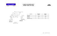
Pickup Box Delete – a Chassis Cab <strong>incomplete</strong> <strong>vehicle</strong><br />
created by ordering a Pickup Box Delete option on an<br />
otherwise completed <strong>vehicle</strong>. (<strong>Ford</strong> Motor Company)<br />
School Bus – a bus that is sold, or introduced in interstate<br />
commerce, for purposes that include carrying students to<br />
and from school or related events, but does not include a<br />
bus designed and sold for operation as a common carrier<br />
in urban transportation. (49CFR571.3)<br />
School Bus (Canada) – a bus designed or equipped primarily<br />
to carry students to and from school. (autobus scolaire)<br />
Seating Reference Point – the unique design H-point, as<br />
defined in SAE J1100 (June 1984), which:<br />
(a) Establishes the rearmost normal design driving or riding<br />
position of each designated seating position in a <strong>vehicle</strong>;<br />
(b) Has X, Y, and Z coordinates established relative to the<br />
designed <strong>vehicle</strong> structure;<br />
(c) Simulates the position of the pivot center of the human<br />
torso and thigh; and<br />
(d) Is the reference point employed to position the two-<br />
dimensional drafting template described in SAE J826<br />
(May 1987).<br />
(abbreviated by <strong>Ford</strong> Motor Company)<br />
Seating Reference Point (Canada) – the unique Design<br />
H-point, as defined in section 2.2.11.1 of SAE Recommended<br />
Practice J1100 (June 1993), that:<br />
(a) establishes the rearmost normal design driving or riding<br />
position of each designated seating position, taking into<br />
account all modes of adjustment – horizontal, vertical<br />
and tilt – in a <strong>vehicle</strong>,<br />
DEFINITIONS<br />
4<br />
(b) has X, Y and Z coordinates, as defined in section 2.2.3<br />
of SAE Recommended Practice J1100 (June 1993),<br />
established relative to the designed <strong>vehicle</strong> structure,<br />
(c) simulates the position of the pivot centre of the human<br />
torso and thigh, and<br />
(d) is the reference point employed to position the H-point<br />
template with the 95th percentile leg, as described in<br />
section 3.1 of SAE Standard J826 (June 1992), or, if that<br />
drafting template cannot be positioned, the reference<br />
point when the seat is in its rearmost adjustment position.<br />
(point de référence de position assise)<br />
Second Unit Body (SUB) – consists of the body structure<br />
and/or all the cargo carrying, work performing, and/or<br />
load bearing components and/or equipment installed by a<br />
subsequent stage manufacturer on an <strong>incomplete</strong> <strong>vehicle</strong>,<br />
such that the <strong>incomplete</strong> <strong>vehicle</strong> becomes a completed<br />
<strong>vehicle</strong>. (<strong>Ford</strong> Motor Company)<br />
Service Body – a type of Second Unit Body (SUB) that<br />
incorporates structural side and rear panels that extend<br />
below frame rail height. (<strong>Ford</strong> Motor Company)<br />
Subsequent Stage Manufacturer – a term which means<br />
either intermediate or final stage manufacturers or both.<br />
(<strong>Ford</strong> Motor Company)<br />
Trimmed Seat – a complete functional seat assembly including<br />
the seat pedestal, seat track, seat base frame, seat back,<br />
recliner mechanism, seat padding, all attaching hardware,<br />
and the final trim material (i.e., cloth, leather, or vinyl). (<strong>Ford</strong><br />
Motor Company)<br />
Truck – a motor <strong>vehicle</strong> with motive power, except a trailer,<br />
designed primarily for the transportation of property or<br />
special purpose equipment. (49CFR571.3)<br />
Truck (Canada) – a <strong>vehicle</strong> designed primarily for the<br />
transportation of property or special-purpose equipment<br />
but does not include a competition <strong>vehicle</strong>, a crawlermounted<br />
<strong>vehicle</strong>, a trailer, a work <strong>vehicle</strong>, a <strong>vehicle</strong> imported<br />
temporarily for special purposes or a <strong>vehicle</strong> designed for<br />
operation exclusively off-road. (camion).<br />
Unloaded Vehicle Weight (UVW) – the weight of a <strong>vehicle</strong><br />
with maximum capacity of all fluids necessary for operation<br />
of the <strong>vehicle</strong>, but without cargo, occupants, or accessories<br />
that are ordinarily removed from the <strong>vehicle</strong> when it is not<br />
in use. (49CFR571.3)<br />
Unloaded Vehicle Weight (Canada) – the weight of a <strong>vehicle</strong><br />
equipped with the containers for the fluids necessary for the<br />
operation of the <strong>vehicle</strong> filled to their maximum capacity, but<br />
without cargo or occupants. (poids du véhicule sans charge)<br />
Untrimmed Seat – the structure including the seat pedestal,<br />
seat track, seat base frame, seat back, recliner mechanism,<br />
seat padding, and all attaching hardware required for a<br />
functional seat assembly without the final trim material<br />
(e.g., cloth, leather, or vinyl) and trim material attaching<br />
components. (<strong>Ford</strong> Motor Company)<br />
Walk-In Van – a step entry city delivery van type <strong>vehicle</strong> that<br />
permits a person to enter the <strong>vehicle</strong> without stooping. This<br />
definition by <strong>Ford</strong> Motor Company is based on information<br />
appearing in 41 FR 54945, published December 16,1976,<br />
and in 42 FR 34288, published July 5,1977.<br />
Walk-In Van (Canada) – a van type of truck in which a person<br />
having a height of 1700 mm can enter the occupant<br />
compartment in an upright position by a front door. (fourgon<br />
à accès en position debout)<br />
F-SERIES (February, 2011)
STATEMENTS OF CONFORMITY<br />
The “Statements of Conformity” section of this <strong>manual</strong> lists the<br />
Federal Motor Vehicle Safety Standards in effect on the date of<br />
manufacture of this <strong>incomplete</strong> <strong>vehicle</strong> that are applicable to the<br />
type(s) of completed <strong>vehicle</strong>s into which this <strong>incomplete</strong> <strong>vehicle</strong><br />
may be manufactured. This date is shown on the label affixed<br />
to the cover of this <strong>manual</strong>. These statements, in most cases,<br />
apply to specific types of <strong>incomplete</strong> or completed <strong>vehicle</strong>s and<br />
identify GVWR and UVW weight ranges.<br />
The <strong>incomplete</strong> <strong>vehicle</strong> type is identified by the 5th, 6th, and<br />
7th digits of the Vehicle Identification Number (VIN); see page<br />
6. The completed <strong>vehicle</strong> types to which this <strong>incomplete</strong> <strong>vehicle</strong><br />
may appropriately be completed is printed on the label, under<br />
the heading “May Be Completed As,” that is affixed to the cover<br />
of this document. The Completed Vehicle Types chart on page<br />
7 identifies how various <strong>incomplete</strong> <strong>vehicle</strong>s with an Optional<br />
Prep Packages or a Trim Code, may be completed.<br />
Each statement of conformity is identified by a safety standard<br />
number located at the left margin. Because there may be<br />
multiple statements of conformity for each safety standard,<br />
use care to select the appropriate statement. Unique CMVSS<br />
requirements will be identified at the conclusion of the<br />
representations for a particular safety standard.<br />
Compliance statements provided in this <strong>manual</strong> are of the<br />
three following types (49CFR568.4):<br />
Type I • A statement that the <strong>vehicle</strong>, when completed, will<br />
conform to the standard if no alterations are made<br />
in identified components of the <strong>incomplete</strong> <strong>vehicle</strong>.<br />
Type II • A statement of specific conditions of final<br />
manufacture under which the <strong>incomplete</strong> <strong>vehicle</strong><br />
manufacturer specifies that the completed <strong>vehicle</strong><br />
will conform to the standard.<br />
Type III • A statement that conformity with the standard<br />
cannot be determined based upon the components<br />
supplied on the <strong>incomplete</strong> <strong>vehicle</strong>, and that<br />
the <strong>incomplete</strong> <strong>vehicle</strong> manufacturer makes no<br />
representation as to conformity with the standard.<br />
F-SERIES (February, 2011)<br />
GENERAL INFORMATION<br />
Information in this section is provided pursuant to Title 49, Code of Federal Regulations, Part 568 – “Vehicles Manufactured in<br />
Two or More Stages”, and Section 6 of the Canadian Motor Vehicle Safety Regulations (CMVSR) – “Vehicles Manufactured in<br />
Stages.” Part 568 specifies that Final Stage Manufacturers must complete <strong>vehicle</strong>s in compliance with all applicable Federal<br />
Motor Vehicle Safety Standards and affix a label to each <strong>incomplete</strong> <strong>vehicle</strong> that is completed in accordance with 49CFR567.5.<br />
Section 6.6 of the CMVSR provides labeling requirements for <strong>vehicle</strong>s that are to be sold in Canada.<br />
DIRECTIONS<br />
5<br />
IMPORTANT:<br />
To rely on the compliance representations in this <strong>manual</strong>,<br />
the <strong>incomplete</strong> <strong>vehicle</strong>s must be completed as one of the<br />
completed <strong>vehicle</strong> types designated on the label affixed<br />
to the cover of this <strong>manual</strong>, and must not exceed the<br />
specified GVWR, GAWRs, or the Unloaded Vehicle Weight<br />
limits when specified in this <strong>manual</strong>.<br />
VEHICLE SPECIAL ORDER (VSO) VEHICLES<br />
VSO <strong>vehicle</strong>s can be identified by a six digit number with the<br />
letters VSO below the digits in the lower right corner of the<br />
Incomplete Vehicle Information label which is affixed to the<br />
driver-door lock pillar. See the sample label on page 6.<br />
The Statements of Conformity section of this <strong>manual</strong> includes<br />
compliance representations for certain VSO <strong>vehicle</strong>s. These<br />
<strong>vehicle</strong>s are identified in the chart on page 7.<br />
FORD TRUCK ASSISTANCE<br />
Throughout this <strong>manual</strong> you will find references to information<br />
found in the <strong>Ford</strong> Truck Body Builders Layout Book. Additional<br />
design recommendations and specifications are also provided<br />
to assist subsequent stage manufacturers in completing<br />
<strong>incomplete</strong> <strong>vehicle</strong>s. The <strong>Ford</strong> Truck Body Builders Layout Book<br />
may be accessed via the web at www.fleet.ford.com/truckbbas<br />
under the “Publications” tab.<br />
The <strong>Ford</strong> Truck Body Builder Advisory Service may be<br />
consulted regarding information contained in this <strong>manual</strong>.<br />
• Call (877) 840-4338<br />
• E-mail via the web at www.fleet.ford.com/truckbbas under<br />
the “Contact Us” tab<br />
GENERAL INFORMATION
INCOMPLETE VEHICLE MANUAL COVER<br />
The cover of this <strong>manual</strong> identifies the <strong>incomplete</strong> <strong>vehicle</strong><br />
configuration for which compliance representations are<br />
contained in this <strong>manual</strong>. Also, a label is affixed to the cover<br />
which includes the Vehicle Identification Number (VIN) for<br />
the specific <strong>vehicle</strong> to which this <strong>manual</strong> belongs. The label<br />
identifies the following information which pertains only to the<br />
<strong>vehicle</strong> with the corresponding VIN.<br />
• The GVWR<br />
• The front and rear GAWRs<br />
• Tire and wheel size<br />
• Cold tire inflation pressure (kPa/PSI)<br />
• Completed <strong>vehicle</strong> type(s) into which the <strong>incomplete</strong><br />
<strong>vehicle</strong> may be manufactured<br />
• Optional prep package when the <strong>vehicle</strong> is so equipped<br />
INCOMPLETE VEHICLE INFORMATION LABEL<br />
All F-Series Super Duty <strong>incomplete</strong> <strong>vehicle</strong>s manufactured<br />
by <strong>Ford</strong> Motor Company will have an Incomplete Vehicle<br />
Information label affixed to the driver-door lock pillar. The<br />
sample labels, shown below, are typical of that provided.<br />
The 5th, 6th, and 7th positions of the Vehicle Identification<br />
Number (VIN) will identify the <strong>incomplete</strong> <strong>vehicle</strong> type. These<br />
three positions are used in the Completed Vehicle Types chart<br />
on page 7.<br />
VEHICLE DESCRIPTION<br />
DATE OF<br />
MANUFACTURE<br />
VEHICLE TYPE<br />
(SEE CHART<br />
ON PAGE 7)<br />
OPTIONAL<br />
PREP PACKAGE<br />
VEHICLE TYPE<br />
(SEE CHART<br />
ON PAGE 7)<br />
INCOMPLETE VEHICLE INFORMATION LABEL<br />
VEHICLE DESCRIPTION<br />
XX/XX<br />
XXXX XXXXXXXXXXXXX<br />
EQUIPPED WITH THE FORD<br />
AMBULANCE PREP PKG.<br />
TYPICAL F-SERIES - U.S.<br />
6<br />
California Air Resources Board (CARB), requires a Vehicle<br />
Identification Number (VIN) Label having a non-contact, barcode,<br />
reading wand capability. The bar-code directly below<br />
the VIN on the Incomplete Vehicle Information label, when<br />
provided, will comply with this regulation.<br />
The Canadian Motor Vehicle Safety Act and Regulations<br />
require installation of an Incomplete Vehicle Information label<br />
with the National Safety mark on it on <strong>vehicle</strong>s manufactured<br />
for sale in Canada. A label representative of those installed by<br />
<strong>Ford</strong> Motor Company assembly plants is shown below.<br />
OPTIONAL PREP PACKAGES<br />
Incomplete <strong>vehicle</strong>s produced by <strong>Ford</strong> Motor Company, in<br />
some instances, are equipped with an optional prep package,<br />
such as Ambulance Prep. The “Completed Vehicle Type” chart<br />
on page 7 will identify <strong>incomplete</strong> <strong>vehicle</strong>s and the optional<br />
prep packages or trim codes that may be required by <strong>Ford</strong><br />
Motor Company if final stage manufacturers wish to rely on<br />
the Statements of Conformity or, in some cases, preserve the<br />
<strong>Ford</strong> Motor Company new <strong>vehicle</strong> warranty.<br />
If an <strong>incomplete</strong> <strong>vehicle</strong> is equipped with an optional prep<br />
package, both the Incomplete Vehicle Information label affixed<br />
to the <strong>vehicle</strong> and the label on the front of this <strong>manual</strong> will<br />
identify the prep package.<br />
410047<br />
VSO<br />
XX/XX<br />
TYPICAL F-SERIES - CANADA<br />
BAR CODE V.I.N<br />
(CALIFORNIA)<br />
VSO<br />
VEHICLE<br />
DATE OF<br />
MANUFACTURE<br />
VSO<br />
VEHICLE<br />
.<br />
F-SERIES (February, 2011)
5TH, 6TH, 7TH<br />
VIN DIGIT<br />
IMPORTANT:<br />
<strong>Ford</strong> Motor Company makes no representation that the<br />
completed <strong>vehicle</strong> types listed above are the only <strong>vehicle</strong><br />
types appropriate for the <strong>incomplete</strong> <strong>vehicle</strong>s listed.<br />
However, if a unit is completed as a <strong>vehicle</strong> type other<br />
than as listed above, the Statements of Conformity may<br />
not be applicable.<br />
F-SERIES (February, 2011)<br />
COMPLETED VEHICLE TYPES<br />
INCOMPLETE VEHICLES<br />
SUPER DUTY F-SERIES<br />
F2A, F3A, F3E F-250/350 Regular Cab 4X2 (SRW)* X X<br />
F2B, F3B, F3F F-250/350 Regular Cab 4X4 (SRW) X X<br />
F3C, F3G, F4G, F5G F-350/450/550 Regular Cab 4X2 (DRW)** X X<br />
F3D, F3H, F4H, F5H F-350/450/550 Regular Cab 4X4 (DRW) X X<br />
X2A, X3A, X3E F-250/350 Super Cab 4X2 (SRW) X X<br />
X2B, X3B, X3F F-250/350 Super Cab 4X4 (SRW) X X<br />
X3C, X3G, X4G, X5G F-350/450/550 Super Cab 4X2 (DRW) X X<br />
X3D, X3H, X4H, X5H F-350/450/550 Super Cab 4X4 (DRW) X X<br />
W2A, W3A, W3E F-250/350 Crew Cab 4X2 (SRW) X X<br />
W2B, W3B, W3F F-250/350 Crew Cab 4X4 (SRW) X X<br />
W3C, W3G, W4G, W5G F-350/450/550 Crew Cab 4X2 (DRW) X X<br />
W3D, W3H, W4H, W5H F-350/450/550 Crew Cab 4X4 (DRW) X X<br />
7<br />
* SRW – Single Rear Wheels<br />
** DRW – Dual Rear Wheels<br />
COMPLETED<br />
VEHICLES<br />
TRUCK MPV<br />
COMPLETED VEHICLE TYPES
STATEMENTS OF CONFORMITY<br />
STATEMENTS OF CONFORMITY<br />
The following Statements of Conformity apply to <strong>vehicle</strong>s that are produced for sale or importation into the United States or<br />
Canada. The term “Incomplete Vehicle Types” in these statements refers to the type of the <strong>vehicle</strong> illustrated on this <strong>manual</strong>’s<br />
cover and listed in the chart on page 7.<br />
The number preceding each Statement of Conformity refers to the number designation for a Part or a Section of Part 571 of the<br />
Federal Motor Vehicle Safety Standard.<br />
The statements provided for each safety standard number are appropriate compliance representations for each Canadian safety<br />
standard number if this <strong>incomplete</strong> <strong>vehicle</strong>, identified by the VIN on the front of the document, was manufactured by <strong>Ford</strong> Motor<br />
Company for sale or use in Canada, except as may be noted at the conclusion of each safety standard number.<br />
101 The statements below are applicable to the Chassis<br />
Cab:<br />
This <strong>vehicle</strong>, when completed, will conform to Standard<br />
101, Controls and Displays if:<br />
• The controls, displays, and their identifications<br />
supplied by <strong>Ford</strong> Motor Company are not removed,<br />
relocated, altered, or modified.<br />
• The components, wiring, and power supply installed by<br />
<strong>Ford</strong> Motor Company to illuminate any control, display,<br />
or their identification are not removed or altered so as<br />
to affect lighting performance.<br />
• Components added to the <strong>vehicle</strong> do not obstruct the<br />
driver’s ability to operate or visually locate the controls,<br />
displays, and their identifications.<br />
• The driver-seat is not replaced, relocated, or modified<br />
other than for the addition of seat trim.<br />
Any controls, displays, and illumination added to<br />
this <strong>vehicle</strong> must conform to the requirements of this<br />
Standard.<br />
102 The statements below are applicable to the Chassis<br />
Cab:<br />
This <strong>vehicle</strong>, when completed, will conform to Standard<br />
102, Transmission Shift Lever Sequence, Starter<br />
Interlock, and Transmission Braking Effect, if no<br />
alterations or adjustments are made to the transmission,<br />
shift cable, transmission outer shift lever, shift cable<br />
bracket, vacuum tubes, vacuum pump system, brakeshift<br />
interlock system, starter interlock system, wiring<br />
circuit from the interlock switch to the power source, and<br />
transmission gear selector indicator (PRNDL).<br />
If an auxiliary transmission is added to this <strong>vehicle</strong>, it<br />
must conform to the requirements of this Standard.<br />
8<br />
103 The statement below is applicable to the Chassis Cab:<br />
This <strong>vehicle</strong>, when completed, will conform to Standard<br />
103, Windshield Defrosting and Defogging Systems, if<br />
no alterations or adjustments are made to heater and<br />
blower assemblies, ducting, operating controls, electrical<br />
circuit from the blower assembly to the power source,<br />
windshield, coolant hoses from the radiator or engine to<br />
the heater, and if no obstructions are added that restrict<br />
or otherwise redirect the air flow from the defroster<br />
outlets to the windshield.<br />
104 The statement below Is applicable to the Chassis Cab:<br />
This <strong>vehicle</strong> when completed, will conform to Standard<br />
104, Windshield Wiping and Washing Systems, if no<br />
alterations are made to the windshield, the windshield<br />
wiping and washing system, including the electrical<br />
circuit from the windshield wiping and washing motors to<br />
the power source, and if no obstructions are added that<br />
restrict or otherwise redirect fluid flow from the washer<br />
nozzles to the windshield.<br />
F-SERIES (February, 2011)
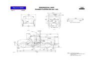
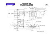
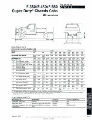
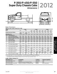
105 INFORMATION<br />
Incomplete <strong>vehicle</strong> weight and dimensional information<br />
required for center of gravity calculations are available in<br />
the <strong>Ford</strong> Source Book. See your local <strong>Ford</strong> Dealer and<br />
refer to appropriate model year and specific <strong>vehicle</strong> for<br />
required information.<br />
Abbreviation definitions and a <strong>vehicle</strong> diagram to assist<br />
with the equations for the Standard 105 segment are<br />
shown on page 10.<br />
105 The statements below are applicable to the Chassis<br />
Cab:<br />
This <strong>vehicle</strong>, when completed, will conform to Standard<br />
105, Hydraulic and Electric Brake Systems, if:<br />
• No alterations, modifications, or replacements are<br />
made to the following:<br />
– Service or parking brake system<br />
– Antilock brake system<br />
– Vacuum system<br />
– Wheels and tires<br />
– Brake system indicator lamp and wiring<br />
– Brake system reservoir labeling<br />
– Suspension ride height or spring rate<br />
– Hydro-boost system<br />
– Power steering pump and lines if used with<br />
Hydro-boost<br />
– Engine belt drive system<br />
• No additional sound deadener or rust proofing<br />
material, that may be applied to the <strong>vehicle</strong>, can<br />
interfere with proper parking brake cable function.<br />
• No part of add on equipment, i.e. toolboxes, flat<br />
bed attaching brackets, etc., can interfere with the<br />
movement of parking brake cables or air flow to rear<br />
brake assembly.<br />
• Any removal of a <strong>Ford</strong> body or chassis component is<br />
accompanied by the addition of equal weight.<br />
• Chassis Cab <strong>vehicle</strong>s with a GVWR of 4536 kg [10,000<br />
lb] or less do not exceed the Maximum Unloaded<br />
Vehicle Weight value in Table F.<br />
• The applicable GAWRs and GVWR weights are not<br />
exceeded.<br />
• The completed <strong>vehicle</strong> must have a vertical center<br />
of gravity (Equation A) of 48.00 inches or less when<br />
measured from the ground.<br />
• The front axle curb weight of the completed <strong>vehicle</strong><br />
(<strong>incomplete</strong> <strong>vehicle</strong> weight + min SUB weight, Table<br />
G) may be reduced by no more than 10% for SRW or<br />
25% for DRW <strong>vehicle</strong>s, using the front axle ground<br />
reaction as manufactured by <strong>Ford</strong> Motor Company.<br />
• The rear axle curb weight of the completed <strong>vehicle</strong><br />
(<strong>incomplete</strong> <strong>vehicle</strong> weight + min SUB weight, Table G)<br />
must be the same or greater than the rear axle ground<br />
reaction as manufactured by <strong>Ford</strong> Motor Company.<br />
REFERENCE: Equation B can be used to determine the<br />
completed <strong>vehicle</strong>’s horizontal center of gravity (CGh).<br />
Abbreviation definitions and a <strong>vehicle</strong> diagram are<br />
provided to assist with the equation on page 10.<br />
F-SERIES (February, 2011)<br />
9<br />
TABLE A<br />
CGhl = Horizontal distance from front axle to cargo CG:<br />
Model<br />
Super Duty F-Series:<br />
WB (in) CGhl (in)†<br />
Regular Cab 137.0 132<br />
Regular Cab 140.8 134<br />
Regular Cab 164.8 146<br />
Regular Cab 188.8 158<br />
Regular Cab 200.8 164<br />
SuperCab 158.0 153<br />
SuperCab 185.8 167<br />
SuperCab 161.8 155<br />
Crew Cab 172.4 165<br />
Crew Cab 176.2 167<br />
Crew Cab 200.2 182<br />
† If CGhI is not given in the table or if the location of your cargo is<br />
not in the normal cargo area, then your CGhI may be estimated<br />
as the distance from the of the front wheel to the horizontal<br />
midpoint of the cargo area.<br />
TABLE B<br />
CGhp = Horizontal distance from front wheel to front<br />
passenger load. (Dimensions are inches)<br />
All Super Duty F-Series = 61.2<br />
TABLE C<br />
CGVC = Vertical distance from ground to chassis CG<br />
(Dimensions are inches)<br />
F-250/350 (4X2) SRW > 8500 lb GVWR = 30.4<br />
F-250/350 (4X4) SRW > 8500 lb GVWR = 31.4<br />
F-350 (4X2) DRW = 30.4<br />
F-350 (4X4) DRW = 31.4<br />
F-450/550 (4X2 & 4X4) DRW = 35.0<br />
TABLE D<br />
SUPER DUTY F-SERIES PASSENGER LOAD<br />
CG hp GVWR [lb] P [lb]<br />
61.2 [in]<br />
EQUATION A<br />
CG v = CG vb W b + CG vc (W c + W l) + CG vp P<br />
GVWR<br />
EQUATION B<br />
P x CGhp (Wrb + Wrc + ( ) + Wrl) x WB<br />
CGh =<br />
WB<br />
GVWR<br />
8800-10,000 400<br />
10,001-19,500 500<br />
TABLE E<br />
SUPER DUTY F-SERIES PASSENGER CG vp<br />
ALL SEATS<br />
4X2 4X4<br />
CG vp 40.3 [in] 43.8 [in]<br />
STATEMENTS OF CONFORMITY
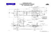
FMVSS 105 DEFINITIONS AND CALCULATION ILLUSTRATION FOR INCOMPLETE SUPER DUTY F-SERIES<br />
P = Passenger load (See Passenger Load Table D).<br />
CGv = Vertical distance from the ground to the center<br />
of gravity [inches] of the completed <strong>vehicle</strong>.<br />
CGh = Horizontal distance from of the front wheels<br />
to the center of gravity [inches] of the completed<br />
<strong>vehicle</strong>.<br />
CGvb = Vertical distance from the ground to the center of<br />
gravity of the SUB and/or permanently attached<br />
added equipment [inches].<br />
CGvc = Vertical distance from the ground to the center<br />
of gravity of the chassis [inches] (including cab<br />
if original equipment). (Taken from Table C).<br />
CGhp = Horizontal distance from the of the front wheels<br />
to the P (passenger load). (See Table B).<br />
CGvp = Vertical distance from the ground to the center<br />
of gravity of the front and rear seat P (passenger<br />
weight). (Taken from Passenger CGvp Table E).<br />
Wb = Weight of the SUB and/or permanently attached<br />
added equipment [pounds].<br />
Wrb = Weight at the rear wheels of the SUB and/<br />
or permanently attached added equipment<br />
[pounds].<br />
Wrc = Weight at the rear wheels of the <strong>vehicle</strong> (chassis<br />
and cab) (fuel tanks full) [pounds]. Including<br />
option weight.<br />
Wc = Weight of the <strong>vehicle</strong> (chassis and cab) (fuel<br />
tanks full) [pounds]. Including option weight.<br />
WB = Vehicle wheelbase [inches].<br />
CG hc<br />
CG hp<br />
STATEMENTS OF CONFORMITY<br />
WB<br />
CG h<br />
W c W t<br />
GVWR<br />
P<br />
CG vp<br />
CG hl<br />
10<br />
W t<br />
= Total unladen weight = (Wb + Wc + P)<br />
GVWR = Gross Vehicle Weight Rating of the <strong>vehicle</strong><br />
[pounds].<br />
WI = Remaining cargo capacity [pounds].<br />
Where: Wl = GVWR - (Wb + Wc + P)<br />
Wrl = Weight of the remaining cargo capacity on the<br />
rear wheels [pounds].<br />
WrI = (CGhI )WI WB<br />
CGhI = Horizontal distance from the of the front wheels<br />
to the cargo center of gravity [inches]. (Taken<br />
from Table A) for many common <strong>vehicle</strong>s. If the<br />
CGhI is not given in the table, then it may be<br />
estimated as the distance from the of the front<br />
wheel to the horizontal midpoint of the cargo<br />
area.<br />
SUB = A Second Unit Body consists of the body<br />
structure and/or all the cargo carrying, work<br />
performing, and/or load bearing components<br />
and/or equipment installed by a subsequent<br />
stage manufacturer on an <strong>incomplete</strong> <strong>vehicle</strong>,<br />
such that the <strong>incomplete</strong> <strong>vehicle</strong> becomes a<br />
completed <strong>vehicle</strong>.<br />
CGhc = Horizontal distance from the of the front wheels<br />
to the center of gravity (inches) of the chassis.<br />
CG OF CHASSIS<br />
CG OF COMPLETED VEHICLE<br />
CG OF SUB<br />
W rl W rb W b<br />
W rc<br />
CG vc<br />
W l<br />
SUB<br />
CG v<br />
CG vb<br />
F-SERIES (February, 2011)
F-SERIES (February, 2011)<br />
TABLE F<br />
MAXIMUM UNLOADED VEHICLE WEIGHTS (UVW) WITH SECOND UNIT BODY (SUB)<br />
( FMVSS 301 FUEL SYSTEM COMPLIANCE )<br />
(Note: This information does not apply to <strong>vehicle</strong>s over 4536 kg [10,000 lb] GVWR)<br />
Model / Cab<br />
PICKUP BOX DELETE / REMOVAL<br />
F-250/350 Regular Cab<br />
F-250/350 SuperCab<br />
F-250/350 Crew Cab<br />
CHASSIS CAB<br />
F-250/350 Regular Cab<br />
F-250/350 SuperCab<br />
F-250/350 Crew Cab<br />
Frame<br />
Width<br />
Wide<br />
Narrow<br />
Drive<br />
11<br />
SUB Maximum CG<br />
Height above Frame<br />
mm [in] (1)<br />
Maximum UVW kg [lb]<br />
Engine<br />
6.2L Gas 6.7L Diesel<br />
447 3547 3515<br />
[17.6] [7819] [7749]<br />
4x2<br />
3547 3905<br />
4x4 610<br />
[7819] [8608]<br />
[24.0] 3547 3905<br />
[7819] [8608]<br />
447 3769 3769<br />
[17.6] [8308] [8308]<br />
4x2<br />
3769 3769<br />
4x4 610<br />
[8308] [8308]<br />
[24.0] 3769 3769<br />
[8308] [8308]<br />
(1) Vertical dimensions are measured from the top surface of the frame at a distance approximately 304.8-457.2 mm<br />
[12--18 in] from the rear of the cab.<br />
STATEMENTS OF CONFORMITY
Model and<br />
Configuration<br />
F-250/350<br />
SRW<br />
F-350<br />
DRW<br />
STATEMENTS OF CONFORMITY<br />
Wide Frame Pickup Box Deletes<br />
F-250/350 956mm [37.7 in]<br />
Body<br />
Style<br />
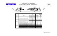
TABLE G<br />
SUPER DUTY F-SERIES VEHICLES MINIMUM SECOND UNIT BODY WEIGHTS<br />
(FMVSS 105 BRAKE COMPLIANCE)<br />
Model and<br />
Configuration<br />
F-350<br />
SRW<br />
F-350<br />
DRW<br />
F-450<br />
DRW<br />
F-550<br />
DRW<br />
Narrow Frame Chassis Cabs<br />
F-350 866mm [34.1 in] and F-450/550 868mm [34.2 in]<br />
12<br />
Wheelbase<br />
mm [in]<br />
Regular Cab 3480 [137]<br />
Super Cab 4013 [158]<br />
Crew Cab 4379 [172.4]<br />
Regular Cab 3480 [137]<br />
Super Cab 4013 [158]<br />
Crew Cab 4379 [172.4]<br />
Body<br />
Style<br />
Wheelbase<br />
mm [in]<br />
Minimum SUB<br />
Weight kg [lb]<br />
172 [380]<br />
191 [420]<br />
Minimum SUB<br />
Weight kg [lb]<br />
Regular Cab 3576 [140.8] 190 [420]<br />
Super Cab 4110 [161.8]<br />
190 [420]<br />
Crew Cab 4475 [176.2] 172 [380]<br />
Regular Cab<br />
3576 [140.8]<br />
4186 [164.8]<br />
190 [420]<br />
204 [450]<br />
Super Cab<br />
4110 [161.8]<br />
4719 [185.8]<br />
190 [420]<br />
214 [470]<br />
Crew Cab<br />
4475 [176.2] 190 [420]<br />
5085 [200.2] 204 [450]<br />
3576 [140.8] 190 [420]<br />
Regular Cab<br />
4186 [164.8]<br />
4795 [188.8]<br />
204 [450]<br />
227 [500]<br />
5100 [200.8] 249 [550]<br />
Super Cab<br />
4110 [161.8]<br />
4719 [185.8]<br />
190 [420]<br />
214 [470]<br />
Crew Cab<br />
4475 [176.2]<br />
5085 [200.2]<br />
190 [420]<br />
204 [450]<br />
Regular Cab<br />
Super Cab<br />
Crew Cab<br />
3576 [140.8]<br />
190 [420]<br />
4186 [164.8] 204 [450]<br />
4795 [188.8] 227 [500]<br />
5100 [200.8] 249 [550]<br />
4110 [161.8]<br />
190 [420]<br />
4719 [185.8] 214 [470]<br />
4475 [176.2] 190 [420]<br />
5085 [200.2] 204 [450]<br />
F-SERIES (February, 2011)
106 The statement below is applicable to the Chassis Cab:<br />
This <strong>vehicle</strong>, when completed, will conform to Standard<br />
106, Brake Hoses, if the brake hose assemblies supplied<br />
by <strong>Ford</strong> Motor Company are not removed, relocated,<br />
altered, or modified and if no brake hose assemblies<br />
are added.<br />
108 The statements below, concerning Standard 108<br />
Lamps, Reflective Devices, and Associated Equipment<br />
are applicable to the Chassis Cab:<br />
No additional components may be added to the<br />
<strong>vehicle</strong> which require the use of tools to remove such<br />
components, for access to the headlamp aiming devices<br />
as provided by <strong>Ford</strong> Motor Company.<br />
Daytime Running Lamps (DRL’s); Light Trucks for sale<br />
or use in Canada are equipped with DRL’s that meet<br />
the Canadian DRL requirements. As manufactured for<br />
Canada, the F-Series <strong>vehicle</strong>s will meet the FMVSS 108<br />
requirements for DRL’s when DRL’s are provided.<br />
Conformity with Standard 108, S.12, Headlamp<br />
Concealment Devices, cannot be determined based<br />
upon the components supplied on of this <strong>incomplete</strong><br />
<strong>vehicle</strong>; accordingly, <strong>Ford</strong> Motor Company makes no<br />
representation as to conformity with this Standard.<br />
FRONT OF<br />
VEHICLE<br />
SUPER DUTY F-SERIES CHASSIS CAB<br />
CENTER HIGH MOUNTED STOP LAMP (CHMSL)<br />
ELECTRICAL CONNECTOR LOCATION<br />
108 The statement below is applicable to the Chassis<br />
Cab with a GVWR of 4536 kg [10,000 lb] or less and a<br />
<strong>vehicle</strong> width less than 2032 mm [80.00 in]:<br />
This <strong>vehicle</strong>, when completed, will conform to Standard<br />
108, Lamps, Reflective Devices, and Associated<br />
Equipment. If the Chassis Cab Center High Mounted<br />
Stop Lamp (CHMSL), when provided, is obstructed from<br />
the rear of the completed <strong>vehicle</strong> it must be replaced<br />
with a CHMSL that meets all the requirements of this<br />
standard and is connected to the electrical power source<br />
as provided by <strong>Ford</strong> Motor Company. See the figure<br />
below for circuit location.<br />
F-SERIES (February, 2011)<br />
CHMSL<br />
FIXED<br />
CIRCUIT<br />
13<br />
108 The statements below are applicable to the Chassis<br />
Cab:<br />
This <strong>vehicle</strong>, when completed, will conform to Standard<br />
108, Lamps, Reflective Devices, and Associated<br />
Equipment, if all the required lighting equipment as<br />
indicated in Table H on next page (identified by the codes<br />
R and S) is designed and installed in accordance with<br />
the requirements of Standard 108 and the directions<br />
contained in this statement. Additionally, if the completed<br />
<strong>vehicle</strong> overall length is 9.14 meters [30 feet] or more,<br />
intermediate side marker lamps and reflex reflectors (not<br />
supplied by <strong>Ford</strong> Motor Company) are also required for<br />
compliance with Standard 108.<br />
The items of equipment which are supplied by <strong>Ford</strong><br />
Motor Company (identified by the code S in Table H,<br />
on next page) are designed and installed to conform<br />
to all the applicable requirements of Standard 108. The<br />
completed <strong>vehicle</strong>, with these components installed,<br />
will conform to Standard 108 if the subsequent stage<br />
manufacturer does not remove, relocate, alter, or modify<br />
such equipment or modify the power supply or wiring to<br />
such equipment, and does not complete the body in such<br />
a configuration as to impair the visibility and conformity<br />
to the photometric requirements of the installed lamps<br />
and reflective devices.<br />
Specific requirements for lighting and associated<br />
equipment are listed by <strong>incomplete</strong> <strong>vehicle</strong> type in Table<br />
H on next page.<br />
Lamps, reflective devices, and associated equipment<br />
necessary to complete the <strong>vehicle</strong> from an <strong>incomplete</strong><br />
<strong>vehicle</strong> must conform to the equipment, locations,<br />
special wiring, visibility, photometric, and performance<br />
requirements of Standard 108 and to the applicable<br />
SAE standards or recommended practices referenced<br />
or sub-referenced in this Standard.<br />
All electrical equipment added to the <strong>vehicle</strong> by<br />
subsequent stage manufacturers must conform to the<br />
wiring practices set forth in the Electrical Wiring Section<br />
of the <strong>Ford</strong> Truck Body Builders Layout Book.<br />
108 Canadian Requirements:<br />
The preceding statements for Standard 108 are<br />
appropriate compliance representations for CMVSS<br />
108, Lighting, if this <strong>vehicle</strong> is manufactured for sale or<br />
use in Canada.<br />
110 U.S. Requirements:<br />
The statement below is applicable to all <strong>incomplete</strong><br />
<strong>vehicle</strong>s with a GVWR of 4536 kg [10,000 lbs] or less:<br />
This <strong>incomplete</strong> <strong>vehicle</strong> does not comply to FMVSS 110.<br />
In order to comply, the final stage manufacturer must<br />
permanently affix a tire placard as specified in paragraph<br />
S4.3 of FMVSS 110, typically to the driver’s side B-pillar.<br />
See below for placard content and note color and format<br />
requirements in S4.3<br />
STATEMENTS OF CONFORMITY
Item<br />
TABLE H<br />
Standard 108 Lighting Equipment<br />
Super Duty<br />
F-Series<br />
Completed<br />
as Truck<br />
or MPV<br />
Headlamps S S<br />
Tail Lamps S S<br />
Stop Lamps S S<br />
Center High Mounted<br />
Stop Lamp (CHMSL) S N<br />
License Plate Lamps S S<br />
Reflex Reflectors – Side Front S S<br />
– Side Rear R R<br />
– Rear S S<br />
Side Marker Lamps – Front S S<br />
– Rear R R<br />
Back-Up Lamps S S<br />
Turn Signal Lamps – Front S S<br />
– Rear S S<br />
Turn Signal Operating Unit S S<br />
Turn Signal Flasher (2) S S<br />
Vehicular Hazard Warning Signal<br />
Operating Unit S S<br />
Vehicular Hazard Warning Signal<br />
Flasher S S<br />
Identification Lamps – Front N S(1)<br />
– Rear N R<br />
Clearance Lamps – Front N S(1)<br />
– Rear N R<br />
Parking Lamps S N<br />
S Required on completed <strong>vehicle</strong> and supplied with the<br />
<strong>incomplete</strong> <strong>vehicle</strong>.<br />
R Required on completed <strong>vehicle</strong> and not supplied with the<br />
<strong>incomplete</strong> <strong>vehicle</strong>.<br />
N Not required for completed <strong>vehicle</strong>.<br />
(1) Cab-mounted clearance lamps, as supplied, do not<br />
adequately indicate overall width of the <strong>vehicle</strong> per<br />
requirements of F/CMVSS 108; additional clearance lamps<br />
will be required. Additional Identification lamps may be<br />
required on the Second Unit Body if the SUB is higher than<br />
the Chassis Cab.<br />
(2) Turn signal flasher function is contained within the Smart Power<br />
Distribution Junction Box features. All chassis cab <strong>vehicle</strong>s,<br />
including pickup box deletes, are configured to provide the<br />
function of a variable-load turn signal flasher.<br />
STATEMENTS OF CONFORMITY<br />
Width less than<br />
2032 mm [80 in]<br />
Width 2032 mm<br />
[80 in] or more<br />
14<br />
111 The statement below is applicable to the Chassis<br />
Cab when not equipped with outside mirrors:<br />
Conformity with Standard 111, Rearview Mirrors, cannot<br />
be determined based upon the components supplied<br />
on this <strong>incomplete</strong> <strong>vehicle</strong>; accordingly, <strong>Ford</strong> Motor<br />
Company makes no representation as to conformity with<br />
this Standard.<br />
111 The statements below are applicable to the Chassis<br />
Cab when equipped with a flat glass mirror on the<br />
passenger-side:<br />
This <strong>vehicle</strong>, when completed, will conform to Standard<br />
111, Rearview Mirrors, if:<br />
• The mirrors and their mounts as supplied by <strong>Ford</strong><br />
Motor Company are not removed, relocated, replaced,<br />
or altered.<br />
• No structural modifications are made to the body which<br />
would affect the stability of the mirror mounts.<br />
• Any modifications or additions made to the <strong>incomplete</strong><br />
<strong>vehicle</strong> must not adversely affect the driver’s view to<br />
the rear in the outside mirrors along both sides of the<br />
<strong>vehicle</strong>.<br />
113 The statement below is applicable to the Chassis Cab:<br />
This <strong>vehicle</strong>, when completed, will conform to Standard<br />
113, Hood Latch System, if the hood latch system as<br />
provided by <strong>Ford</strong> Motor Company is not removed or<br />
altered.<br />
114 The statements below are applicable to the Chassis<br />
Cab when completed as either a MPV or a Truck with<br />
a GVWR of 4536 kg [10,000 lb] or less:<br />
This <strong>vehicle</strong>, when completed, will conform to Standard<br />
114, Theft Protection and Rollaway Prevention, if the<br />
following components, to the extent provided by <strong>Ford</strong><br />
Motor Company, are not removed, relocated, altered, or<br />
modified in any way:<br />
• Steering column locking mechanism system<br />
• Ignition key/transmission shift interlock locking system<br />
• Ignition key-locking system<br />
• Key warning buzzer system<br />
If any of the above components are added to the <strong>vehicle</strong><br />
they must conform to the requirements of this Standard.<br />
115 Canadian Requirements:<br />
The statements for Part 565.4 are appropriate compliance<br />
representations for CMVSS 115, Vehicle Identification<br />
Number, if this <strong>incomplete</strong> <strong>vehicle</strong> was manufactured for<br />
sale or use in Canada.<br />
116 The statement below is applicable to the Chassis<br />
Cab:<br />
This <strong>vehicle</strong>, when completed, will conform to Standard<br />
116, Motor Vehicle Brake Fluids, so long as any<br />
brake fluid added or replaced conforms to the DOT 3<br />
specifications of the standard and contaminants are not<br />
introduced into the hydraulic brake system.<br />
F-SERIES (February, 2011)
118 The statement below is applicable to the Chassis Cab<br />
not equipped with power-operated windows, partition<br />
or roof panel systems and their actuation devices<br />
when completed as either a MPV or a Truck with a<br />
GVWR of 4536 kg [10,000 lb] or less:<br />
Conformity with Standard 118, Power-Operated Window,<br />
Partition, and Roof Panel Systems, cannot be determined<br />
based upon the components supplied on this <strong>incomplete</strong><br />
<strong>vehicle</strong>; accordingly, <strong>Ford</strong> Motor Company makes no<br />
representation as to conformity with this Standard. If any<br />
power-operated window, partition, or roof panel systems<br />
are installed by subsequent stage manufacturers, they<br />
must conform to the requirements of Standard 118.<br />
118 The statement below is applicable to the Chassis Cab<br />
equipped with power-operated windows, partition or<br />
roof panel systems and their actuation devices when<br />
completed as either a MPV or a Truck with a GVWR of<br />
4536 kg [10,000 lb] or less:<br />
This <strong>vehicle</strong>, when completed, will conform to Standard<br />
118, Power-Operated Window, Partition, and Roof Panel<br />
Systems, if the power-operated windows, motors, wiring,<br />
and key and switch activation systems, where provided<br />
by <strong>Ford</strong> Motor Company, are not removed, relocated,<br />
altered, or modified in any way. If additional poweroperated<br />
window, partition, or roof panel systems are<br />
installed by subsequent stage manufacturers, they must<br />
conform to the requirements of Standard 118.<br />
119 The statement below is applicable to the Chassis Cab:<br />
All tires supplied by <strong>Ford</strong> Motor Company are in full<br />
conformity with Standard 119, New Pneumatic Tires<br />
for Motor Vehicles with a GVWR of more than 4536<br />
kilograms [10,000 pounds].<br />
If additional tires are installed or the existing tires are<br />
replaced by subsequent stage manufacturers, they must<br />
conform to the requirements of Standard 119.<br />
120 The statement below is applicable to the Chassis Cab:<br />
This <strong>vehicle</strong>, when completed, will conform to the tire<br />
and rim selection requirements of Standard 120, Tire<br />
Selection and Rims for Motor Vehicles with a GVWR<br />
of more than 4,536 kilograms [10,000 pounds], if the<br />
tire and rim assemblies and the Incomplete Vehicle<br />
Information label that is affixed to the <strong>vehicle</strong> are not<br />
removed, altered, or replaced.<br />
124 The statements below are applicable to the Chassis Cab:<br />
This <strong>vehicle</strong>, when completed, will conform to Standard<br />
124, Accelerator Control Systems, if:<br />
• No alterations are made to the accelerator pedal,<br />
mounting hardware, adjustable pedal mechanism, or<br />
other components of the accelerator control system<br />
as installed by <strong>Ford</strong> Motor Company.<br />
• No equipment is added nor existing equipment modified<br />
which would restrict operation of the accelerator control<br />
system.<br />
• No alterations are made to the Pedal Position Sensor<br />
and all associated hardware and wiring. See the figure<br />
below for component identification.<br />
F-SERIES (February, 2011)<br />
15<br />
ELECTRONIC ACCELERATOR CONTROL (Typical)<br />
126 The statement below is applicable to the Chassis Cab,<br />
including Pickup Box Delete, if the <strong>vehicle</strong> GVWR is<br />
4536 kg [10,000 lb] or less:<br />
Vehicles built in two or more stages, or that are altered,<br />
are not required to comply with Standard 126, Electronic<br />
Stability Control Systems, until September 1, <strong>2012</strong>;<br />
however, <strong>vehicle</strong>s equipped with a Roll Stability Control<br />
(RSC) feature when completed will conform to Standard<br />
126 if:<br />
• The vertical center of gravity (CGv) is less than or<br />
equal to 42.6" and no modifications have been made<br />
to the components of the braking system, suspension<br />
system, wheels and tires. Completed <strong>vehicle</strong> weight<br />
should not exceed Maximum Unloaded Vehicle<br />
Weights (UVW) as shown in Table F on page 11.<br />
For <strong>vehicle</strong>s equipped with RSC, if the vertical center of<br />
gravity (CGv) of the <strong>vehicle</strong> is above 42.6", <strong>Ford</strong> Motor<br />
Company makes no representation as to conformity with<br />
this Standard.<br />
138 The statement below is applicable to all single rear<br />
wheel (SRW) <strong>incomplete</strong> <strong>vehicle</strong> types if the GVWR is<br />
4536 kg [10,000 lb] or less (if equipped):<br />
The Tire Pressure Monitoring System is subject to<br />
interference from the addition of metallic structures<br />
between the wheel-mounted sensor transmitters and<br />
the on-board receiver.<br />
This <strong>vehicle</strong>, when completed, will conform to Standard<br />
138, Tire Pressure Monitoring Systems, if:<br />
• No alterations are made to the tire pressure sensors<br />
(valve stems), wheels, tires, recommended tire pressures,<br />
electrical Smart Power Distribution Junction Box,<br />
instrument cluster, instrument panel wiring, or software<br />
calibrations<br />
• Wheel bases are not lengthened beyond 176 inches<br />
• No equipment that emits radio frequency (RF) energy<br />
is added to the <strong>vehicle</strong><br />
• After <strong>vehicle</strong> upfit, function of the Tire Pressure<br />
Monitoring System is verified in accordance with<br />
FMVSS 138<br />
STATEMENTS OF CONFORMITY
139 The statement below is applicable to all <strong>incomplete</strong><br />
<strong>vehicle</strong> types:<br />
All tires supplied by <strong>Ford</strong> Motor Company are in full<br />
conformity with Standard 139, New Pneumatic Radial<br />
Tires for Light Vehicles.<br />
If additional tires are installed or the existing tires are<br />
replaced by subsequent stage manufacturers, they must<br />
conform to the requirements of Standard 139.<br />
201 The statements below are applicable to the Chassis<br />
Cab with a GVWR of 4536 kg [10,000 lb] or less:<br />
This <strong>vehicle</strong>, when completed, will conform to Standard<br />
201, Occupant Protection in Interior Impact (excluding<br />
U.S. Section 6 requirements addressed separately), if<br />
the following components, as provided by <strong>Ford</strong> Motor<br />
Company, are not removed, relocated, altered, or<br />
modified in any way:<br />
• Instrument panel<br />
• Interior compartment doors<br />
• Sun visors<br />
• Arm rests<br />
Seat backs of front seats installed by <strong>Ford</strong> Motor Company<br />
are designed to meet the seat back requirements<br />
of Standard 201. The seat mounted armrest on an<br />
untrimmed front seat must be completed so as to meet<br />
the requirements of this Standard.<br />
If any of the above mentioned components (including<br />
front seats) are added to the <strong>incomplete</strong> <strong>vehicle</strong> by a<br />
subsequent stage manufacturer, these components must<br />
conform to the requirements of Standard 201 where<br />
applicable.<br />
Because conformity of a completed <strong>vehicle</strong> to the seat<br />
back requirements of this standard is dependent upon<br />
the location of a seat installed by a subsequent stage<br />
manufacturer to the rear of another seat, <strong>Ford</strong> Motor<br />
Company makes no representation as to compliance<br />
of a completed <strong>vehicle</strong> to the seat back requirements if<br />
such a seat is installed.<br />
If a <strong>vehicle</strong> is equipped with a Passenger-side Air Bag<br />
Delete option, a right-hand passenger seat should<br />
never be installed. If such a seat is installed, <strong>Ford</strong> Motor<br />
Company makes no representation as to the compliance<br />
of the completed <strong>vehicle</strong> to Standard 201.<br />
STATEMENTS OF CONFORMITY<br />
16<br />
201U U.S. Requirements (Section S6):<br />
This <strong>vehicle</strong> when completed, will conform to Standard<br />
201U, Occupant Protection in Interior Impact – Section 6,<br />
Requirements for Upper Interior Head Impact Protection,<br />
if the following com ponents as provided by <strong>Ford</strong> Motor<br />
Company, are not removed, relocated, altered, modified<br />
or additions added to the:<br />
• A, B, Rear, or other Pillar and Trim, and Assist Handles<br />
• Seat Belt ‘D’-Rings/Adjusters and ‘D’-Ring Covers and<br />
Sling Systems<br />
• Canopy Air Curtain (if equipped)<br />
• Front or Rear Header and Trim<br />
• Side Rails, Trim, Coat Hooks and Ride Handles<br />
• Upper Roof and Trim<br />
• Exterior Windshield Trim<br />
• Exterior Roof Drain Ditches<br />
• Primary and Secondary Door/Body Seals at all door<br />
opening locations in the <strong>vehicle</strong><br />
• Sunvisors and attachment hardware<br />
• Changes to the design Seating Reference Point (SRP)<br />
with modifications to the Seat System<br />
If any of the above components are added to the<br />
<strong>incomplete</strong> <strong>vehicle</strong> by a subsequent stage manufacturer,<br />
these components must conform to the requirements of<br />
Standard 201U where applicable.<br />
202a The statements below are applicable to the Chassis<br />
Cab if the GVWR is 4536 kg [10,000 lb] or less:<br />
This <strong>vehicle</strong> when completed, will conform to Standard<br />
202, Head Restraints, if:<br />
• No alterations are made to the head restraints, the<br />
seat assemblies and their anchorages, the floor pan,<br />
or floor pan reinforcements.<br />
• The added seat trim, on <strong>vehicle</strong>s equipped with<br />
untrimmed front seats, is installed so that the physical<br />
dimension requirements for the head restraint, in this<br />
Standard, are met.<br />
Any front outboard passenger seat, added to a cutaway<br />
equipped with the School Bus Prep Package and when<br />
completed as a truck, MPV, or bus (not school bus), must<br />
conform with the requirements of this Standard.<br />
203 The statement below is applicable to the Chassis Cab<br />
if the GVWR is 4536 kg [10,000 lb] or less:<br />
This <strong>vehicle</strong>, when completed, will conform to Standard<br />
203, Impact Protection for the Driver from the Steering<br />
Control System, if the steering control system is not<br />
removed, relocated, altered, or modified in any way and<br />
no components or attachments are added to the steering<br />
control system that can catch the driver’s clothing or<br />
jewelry during normal driving maneuvers.<br />
203 Canadian Requirements:<br />
The preceding statements for FMVSS 203 are<br />
appropriate compliance representations for CMVSS<br />
203, Driver Impact Protection, if this <strong>incomplete</strong> <strong>vehicle</strong><br />
was manufactured for sale or use in Canada. In such<br />
a case, the Basic (Stripped) Chassis will comply if no<br />
components or attachments are added to the steering<br />
control system that can catch the driver’s clothing or<br />
jewelry during normal driving maneuvers.<br />
F-SERIES (February, 2011)
204 INFORMATION<br />
Refer to the Design Recommendation section of the <strong>Ford</strong><br />
Truck Body Builders Layout Book for Second Unit Body<br />
Attachment information that may aid in designing second<br />
unit bodies and their attachments to be compatible with<br />
F-Series <strong>vehicle</strong>s.<br />
204 The statements below are applicable to the Chassis<br />
Cab if the GVWR is 4536 kg [10,000 lb] or less and the<br />
Unloaded Vehicle Weight, when completed, is 2495 kg<br />
[5500 lb] or less:<br />
This <strong>vehicle</strong>, when completed, will conform to Standard<br />
204, Steering Control Rearward Displacement, if:<br />
• The Unloaded Vehicle Weight does not exceed the<br />
appropriate weight on Table F for F-Series Chassis<br />
Cab type <strong>vehicle</strong>s.<br />
• No components are added which could influence the<br />
rearward displacement of the steering column.<br />
• The steering column, steering intermediate and<br />
coupling shaft, steering wheel, steering gear, steering<br />
linkage, related structural components, and attaching<br />
hardware, as installed by <strong>Ford</strong> Motor Company, are not<br />
removed, relocated, altered, or modified in any way.<br />
• No alteration or modifications are made to the body<br />
chassis, drivetrain, or front suspension from the B-pillar<br />
forward.<br />
205 The statement below is applicable to the Chassis Cab:<br />
This <strong>vehicle</strong>, when completed, will conform to Standard<br />
205, Glazing Materials, if no alterations to or replacements<br />
of the installed glazing materials are made and if<br />
additional glazing materials installed by a subsequent<br />
stage manufacturer conforms to the requirements of<br />
Standard 205.<br />
206 The statements below are applicable to the Chassis<br />
Cab when completed as a Truck:<br />
This <strong>vehicle</strong>, when completed, will conform to Standard<br />
206, Door Locks and Door Retention Components, if no<br />
alterations or adjustments are made to the door, door<br />
pillar structure, door locks, door latches, striker plates,<br />
hinges, and attaching hardware as installed by <strong>Ford</strong><br />
Motor Company.<br />
Any door added to this <strong>vehicle</strong> by a subsequent stage<br />
manufacturer must be equipped with door locks and door<br />
retention components that conform with this Standard.<br />
207 The statements below are applicable to the Chassis<br />
Cab when equipped with <strong>Ford</strong> trimmed front seats:<br />
This <strong>vehicle</strong>, when completed, will conform to Standard<br />
207, Seating Systems, if no alterations are made to the<br />
seat assemblies, their anchorages, the floor pan, or floor<br />
pan reinforcements. Any seating system added to this<br />
<strong>vehicle</strong> must conform to applicable requirements of this<br />
Standard.<br />
F-SERIES (February, 2011)<br />
17<br />
208 The statement below is applicable to the Chassis<br />
Cab when equipped with <strong>Ford</strong> trimmed front seats<br />
and either the GVWR is over 3856 kg [8500 lb], the<br />
Unloaded Vehicle Weight, when completed, is over<br />
2495 kg [5500 lb], or the <strong>vehicle</strong>s are manufactured<br />
for operation by persons with disabilities:<br />
This <strong>vehicle</strong>, when completed, will conform to Standard<br />
208, Occupant Crash Protection, if:<br />
• The seat belts, seat belt warning system, passenger air<br />
bag deactivation switch (if so equipped), and attaching<br />
hardware installed by <strong>Ford</strong> Motor Company are not<br />
removed, relocated, altered, or modified.<br />
• No actions are taken which would impair the integrity<br />
of the belt and seat belt warning systems. (A seat belt<br />
warning system is not required for a <strong>vehicle</strong> with a<br />
GVWR over 4536 kg [10,000 lb] ).<br />
• The Air Bag Supplemental Restraint System Information<br />
Labels that are affixed to the front sunvisors are visible<br />
and not altered, modified, or removed. If the Air Bag<br />
Supplemental Restraint System Information Labels are<br />
not affixed to the front visors but shipped in dunnage,<br />
the following is necessary to meet Standard 208:<br />
– The information label must be permanently affixed<br />
to each visor in an upright position readable from<br />
the driver’s or passenger’s seating position.<br />
– If the label is not visible when the visor is stored (up<br />
position), an Air Bag Alert Label shall be placed on<br />
the visible surface of the visor as specified in Section<br />
4.5.1(c) of Standard 208.<br />
Any seat belt assemblies added to this <strong>vehicle</strong> must<br />
conform to the applicable requirements of this Standard.<br />
208 Canadian Requirements:<br />
The preceding statements are appropriate compliance<br />
representations for CMVSS 208, Seat Belt Installation, if<br />
this <strong>incomplete</strong> <strong>vehicle</strong> was manufactured for sale or use<br />
in Canada. In such a case, CMVSS 208 paragraphs (13),<br />
(14), and (15) are substituted for the reference to FMVSS<br />
208 Section 7.1; CMVSS 208 paragraph (20) should<br />
be substituted for the reference to FMVSS 208 Section<br />
7.2; and CMVSS 208 paragraphs (29), (30), (31), (32),<br />
(33), (34), (35), (36), (37), (38), (39), and (40) should be<br />
substituted for the reference to FMVSS 208 Section 7.4.<br />
WARNING:<br />
VEHICLES OVER 3856 kg [8500 lb] GVWR AND<br />
2495 kg [5500 lb] UVW ARE EQUIPPED WITH<br />
SUPPLEMENTAL RESTRAINT SYSTEMS (AIR<br />
BAGS) WHICH ARE STANDARD ON THE DRIVER’S<br />
SIDE, AND STANDARD OR OPTIONAL FOR THE<br />
PASSENGER SIDE. MODIFICATIONS TO THE VEHICLE<br />
FORWARD OF THE CRASH SENSOR MAY AFFECT<br />
THE DEPLOYMENT OF THE AIR BAG WHEN SO<br />
EQUIPPED. REFER TO THE FORD TRUCK BODY<br />
BUILDERS LAYOUT BOOK FOR SNOW PLOW<br />
PREPARATION PACKAGES AND INSTALLATION<br />
INSTRUCTIONS WHICH ARE COMPATIBLE WITH<br />
AIR BAGS.<br />
STATEMENTS OF CONFORMITY
209 The statements below are applicable to the Chassis<br />
Cab with front seat(s):<br />
This <strong>vehicle</strong>, when completed, will conform to Standard<br />
209, Seat Belt Assemblies, if:<br />
• No alterations or replacements are made to the seat<br />
belt assemblies and attaching hardware.<br />
• No action is taken that would impair the integrity of the<br />
seat belt system provided.<br />
Any seat belt assemblies added to a <strong>vehicle</strong> must<br />
conform to the requirements of this Standard.<br />
209 Canadian Requirements:<br />
The preceding statements for FMVSS 209 are appropriate<br />
compliance representations for CMVSS 209, Seat Belt<br />
Assemblies, if this <strong>incomplete</strong> <strong>vehicle</strong> was manufactured<br />
for sale or use in Canada. In such a case, CMVSS 209<br />
paragraphs (2) and 93), (4) and (5), (14), (15), and (7)<br />
are substituted for the reference to FMVSS 209 Sections<br />
4.1(b), 9c), (e), (g), and (h), respectively.<br />
SUPER DUTY F-SERIES OCCUPANT PROTECTION ZONE<br />
STATEMENTS OF CONFORMITY<br />
DRIVER<br />
AIRBAG<br />
MODULE<br />
18<br />
210 The statements below are applicable to the Chassis<br />
Cab:<br />
This <strong>vehicle</strong>, when completed, will conform to Standard<br />
210, Seat Belt Assembly Anchorages, if:<br />
• No alterations are made to the front seat belt<br />
anchorages, front seat belt assemblies, floor pan, floor<br />
pan reinforcements, or body mounts.<br />
• No alternations are made to the rear cab panel or roof<br />
for the Chassis Cab.<br />
Chassis Cab <strong>vehicle</strong>s may have additional seat belt<br />
anchorages for designated seating positions on optional<br />
seats not provided on <strong>incomplete</strong> <strong>vehicle</strong>s. These<br />
locations apply to specific hardware and designated<br />
seating positions used in <strong>Ford</strong> completed <strong>vehicle</strong>s. If<br />
these anchorages are used without the appropriate<br />
<strong>Ford</strong> seats, seat belt systems, and hardware, <strong>Ford</strong> Motor<br />
Company makes no representation as to conformity with<br />
this Standard.<br />
AIRBAG<br />
DEACTIVATION<br />
SWITCH<br />
ELECTRONIC CRASH<br />
SENSOR MODULE<br />
DO NOT INSTALL ADDITIONAL COMPONENTS IN THE<br />
SHADED AREAS, NOR ALTER OR MODIFY THESE AREAS.<br />
DO NOT MODIFY NOR ALTER ANY COMPONENTS OR AREAS<br />
OF THE VEHICLE IN THE VICINITY OF THE COMPONENTS<br />
THAT ARE IDENTIFIED IN THIS ILLUSTRATION.<br />
DO NOT MODIFY NOR ALTER THE FRONT CRASH SENSOR LOCATED<br />
UNDER THE RADIATOR ON THE FRONT LOWER TIE BAR.<br />
PASSENGER<br />
AIRBAG<br />
MODULE<br />
SUPER DUTY F-SERIES OCCUPANT PROTECTION ZONE &<br />
SUPPLEMENTAL RESTRAINT SYSTEM (AIRBAGS, SENSORS AND WIRING)<br />
F-SERIES (February, 2011)
210.1 Canadian Requirements:<br />
The statement below is applicable to the Chassis<br />
Cab with a GVWR of 3856 kg [8500 lb] or less and an<br />
unloaded <strong>vehicle</strong> weight of 2495 kg [5500 lb] or less.<br />
This <strong>vehicle</strong>, when completed, will conform to Standard<br />
210.1, User-Ready Tether Anchorages for Restraint<br />
Systems, if:<br />
• No alterations are made to the passenger seat tether<br />
anchorages or LATCH lower anchors, access to the<br />
anchorages is not restricted, and no alterations are<br />
made to the seat assemblies, their anchorages, the<br />
floor pan, or floor pan reinforcements.<br />
212/ Note<br />
219 The terms “body” or “body structure,” in the 212 and<br />
219 statements that follow, include any equipment<br />
permanently attached to that body or body structure<br />
installed by the subsequent stage manufacturer as well<br />
as the basic body or body structure.<br />
212/ INFORMATION<br />
219 Refer to the Design Recommendations section in the<br />
<strong>Ford</strong> Truck Body Builders Layout Book for Second Unit<br />
Body Attachment information to aid in designing second<br />
unit bodies and their attachments for compatibility with<br />
F-Series <strong>vehicle</strong>s.<br />
212/ The statements below are applicable to the Chassis<br />
219 Cab if the GVWR is 4536 kg [10,000 lb] or less:<br />
This <strong>vehicle</strong>, when completed, will conform to Standard<br />
212 Windshield Mounting, and Standard 219, Windshield<br />
Zone Intrusion, if:<br />
• The following windshield system components, related<br />
structural components, and hardware, as installed by<br />
<strong>Ford</strong> Motor Company, are not removed, relocated,<br />
altered, or modified in any way except as specified in<br />
this <strong>manual</strong>:<br />
– Windshield and windshield mounting system<br />
– Cab and front end structural components including<br />
the roof, pillars, cowl, cowl reinforcements,<br />
hood, doors, fenders, hood restrictors and apron<br />
reinforcements, and frame and frame reinforcements<br />
– Radio antenna and air cleaner assembly<br />
– Doors and hood mounting, hinging, and latching<br />
systems<br />
– Hood ornamentation<br />
– Bumper and bumper mounting system †<br />
• No alteration or modification made to the <strong>incomplete</strong><br />
<strong>vehicle</strong> as manufactured by <strong>Ford</strong> Motor Company<br />
and no components or structure installed by a<br />
subsequent stage manufacturer results in any loss of<br />
windshield retention (as defined in Standard 212) or<br />
any penetration of the inner surface of the windshield<br />
or intrusion into the protected zone (as defined in<br />
Standard 219) when the <strong>vehicle</strong> is impacted in any<br />
manner specified by applicable provisions of Standard<br />
212 or Standard 219. Conformity to Standards 212 and<br />
219 for a <strong>vehicle</strong> having an Unloaded Vehicle Weight<br />
greater than 2495 kg [5500 lb] is established by testing<br />
a representative <strong>vehicle</strong> at an Unloaded Vehicle Weight<br />
of 2495 kg [5500 lb] as permitted by S6.1 (b) and S7.7<br />
(b) of Standards 212 and 219, respectively.<br />
F-SERIES (February, 2011)<br />
19<br />
• The front end of the body installed by the subsequent<br />
stage manufacturer is located at least 76.2 mm [3.0<br />
in] rearward of the rearmost point of the cab.<br />
– The body installed by the subsequent stage<br />
manufacturer is mounted securely and so designed<br />
that, when the completed <strong>vehicle</strong> is impacted in<br />
any manner specified by applicable provisions<br />
of Standards 212 and 219, body deformation or<br />
movement relative to the frame does not result in any<br />
separation or loss of body attachment to the frame.<br />
• The maximum SUB weight and SUB center of gravity<br />
as installed by the subsequent stage manufacturer<br />
and the Unloaded Vehicle Weight does not exceed<br />
the values specified in Table F, corresponding to the<br />
<strong>incomplete</strong> <strong>vehicle</strong> type, wheelbase, and engine size.<br />
212/ Canadian Requirements:<br />
219 The preceding statements for FMVSS 212/219 are<br />
appropriate compliance representations for CMVSS 212,<br />
Windshield Mounting, and CMVSS 219 Windshield Zone<br />
Intrusion, if this <strong>incomplete</strong> <strong>vehicle</strong> was manufactured for<br />
sale or use in Canada. In such a case, CMVSS 212 and<br />
219 paragraphs (5.1) and (8)(b) are substituted for the<br />
reference to FMVSS 212 and 219 Sections 6.1(b) and<br />
7.7(b) respectively.<br />
213 The statement below is applicable to the Chassis<br />
Cab:<br />
Conformity with Standard 213, Child Restraint Systems,<br />
cannot be determined based upon the components<br />
supplied on the <strong>incomplete</strong> <strong>vehicle</strong>; accordingly<br />
<strong>Ford</strong> Motor Company makes no representation as<br />
to conformity with this Standard. Any child restraint<br />
system that is added or incorporated into the design<br />
of a designated seating position must conform to the<br />
requirements of this standard.<br />
214 The statements below are applicable to the Chassis<br />
Cab if the GVWR is 4536 kg [10,000 lb] or less:<br />
This <strong>vehicle</strong>, when completed, will conform to Standard<br />
214, Side Impact Protection, if:<br />
• No alterations, modifications, or replacements are<br />
made to the door, surrounding door structure, door<br />
hinges, door latches and strikers, or any attaching<br />
hardware as provided by <strong>Ford</strong> Motor Company.<br />
219 See combined statements under “212/219” for all<br />
<strong>vehicle</strong> types.<br />
225 The statement below is applicable to the Chassis Cab:<br />
This <strong>vehicle</strong>, when completed, will conform to Standard<br />
225, Child Restraint Anchorage Systems, if:<br />
• No alterations are made to the front passenger seat<br />
tether anchorages and access to the anchorages is<br />
not restricted, and no alterations are made to the seat<br />
assemblies, their anchorages, the floor pan, or floor<br />
pan reinforcements, and no seats are added.<br />
Because the addition of seats would change compliance<br />
with this Standard, <strong>Ford</strong> Motor Company makes no<br />
representations as to conformity with this Standard for<br />
any <strong>vehicle</strong> that has seats added by the intermediate or<br />
final stage manufacturers.<br />
† Temporary removal of the front bumper and front bumper<br />
mounting system during manufacture and reinstallation in<br />
accordance with the instructions provided in the <strong>Ford</strong> Truck<br />
Shop Manual should not adversely affect the compliance of<br />
a completed <strong>vehicle</strong> to Standards 212 and 219.<br />
STATEMENTS OF CONFORMITY
301 Note<br />
The terms “body” or “body structure”, in the 301<br />
statements that follow include not only the basic body<br />
or body structure but also any equipment permanently<br />
attached to that body or body structure installed by the<br />
subsequent stage manufacturer.<br />
301 INFORMATION<br />
The Unloaded Vehicle Weight of the completed <strong>vehicle</strong><br />
may significantly affect its capability to meet the<br />
requirements of Standard 301, Fuel System Integrity.<br />
Completed <strong>vehicle</strong>s manufactured by <strong>Ford</strong> Motor<br />
Company that are tested to demonstrate compliance<br />
with Standard 301 are loaded pursuant to S7.1.6 of the<br />
Standard. The test weights of these <strong>vehicle</strong>s comprise<br />
the Unloaded Vehicle Weights including the weights of<br />
all available regular production options plus the loads<br />
specified by S7.1.6. These test weights are less than<br />
the respective designated Gross Vehicle Weight Ratings.<br />
In addition to the specific statements below, refer to the<br />
“Design Recommendations” section of the <strong>Ford</strong> Truck<br />
Body Builders Layout Book for fuel system information<br />
to assist in designing fuel systems and the Second Unit<br />
Body Attachment recommendations for information to aid<br />
in designing second unit bodies and their attachments to<br />
be compatible with Super Duty F-Series <strong>vehicle</strong>s.<br />
301 In addition to the statements pertaining to particular<br />
<strong>incomplete</strong> <strong>vehicle</strong> types which follow, the statements<br />
immediately below, concerning Standard 301 Fuel<br />
System Integrity, apply to all <strong>incomplete</strong> <strong>vehicle</strong> types<br />
to be completed with a GVWR of 4536 kg [10,000 lb]<br />
or less:<br />
• If a fuel line is to be disconnected, refer to the<br />
appropriate <strong>Ford</strong> Service Manual for proper removal<br />
and installation procedures.<br />
• When welding near fuel system components, all<br />
metallic components must be adequately shielded and<br />
protected from heat or weld splatter. All non-metallic<br />
components must be removed.<br />
NOTE: Some <strong>incomplete</strong> <strong>vehicle</strong>s are equipped with<br />
nylon fuel tubes. In the event that the tubes require<br />
repair or replacement, only <strong>Ford</strong> Motor Company<br />
approved parts or their equivalents should be used.<br />
301 The statements below are applicable to the Chassis<br />
Cab if the <strong>vehicle</strong> GVWR is 4536 kg [10,000 lb] or less:<br />
This <strong>vehicle</strong>, when completed, will conform to Standard<br />
301, Fuel System Integrity, if:<br />
• The following fuel system and frame components as<br />
installed by <strong>Ford</strong> Motor Company are not removed,<br />
relocated, altered, or modified in any way (except<br />
as specified in the representations following this<br />
paragraph):<br />
– Fuel tank(s) and attachment hardware, including<br />
sending unit, vapor valve, fuel tank shield, pressure<br />
transducer, and in-tank electric fuel pump<br />
– Fuel filler cap(s), pipe(s), hose(s), and attachment<br />
hardware<br />
STATEMENTS OF CONFORMITY<br />
20<br />
– Fuel lines, routing, and attachments<br />
– Vapor line(s) and carbon canister – (gasoline engine<br />
application)<br />
– Fuel pump<br />
– Fuel filter<br />
– Fuel water separator fuel filter/primer, fuel line<br />
heater, and injection pump – (diesel engine only)<br />
– Fuel shut off switch (inertia switch)<br />
– Trailer hitch receiver on Pickup Box Delete <strong>vehicle</strong>s<br />
(Sales Code 66D)<br />
• Pickup Box Delete <strong>vehicle</strong>s (Sales Code 66D)<br />
incorporate an outboard LH frame-mounted bracket<br />
(Ref: Figure A1) required as part of pickup truck<br />
Standard 301 compliance. <strong>Ford</strong> recommends that this<br />
bracket not be removed for SUB installation, however,<br />
if there is an interference with a service body upfit<br />
it may be removed and still maintain Standard 301<br />
compliance. All other SUB upfits, including platform &<br />
stake bodies, require this bracket remain attached as<br />
installed by <strong>Ford</strong> Motor Company.<br />
• Chassis Cab <strong>vehicle</strong>s (non-Pickup Box Deletes)<br />
with a GVWR of 4536 kg [10,000 lb] or less require<br />
installation of a blocker beam receiver assembly as<br />
described in Figure A2 or A3.<br />
• No other alteration or modification made to the<br />
<strong>incomplete</strong> <strong>vehicle</strong> as manufactured by <strong>Ford</strong> Motor<br />
Company and no other components or structure<br />
installed by a subsequent stage manufacturer result<br />
in penetration, separation, or other damage to the<br />
fuel system or any portion thereof when the <strong>vehicle</strong><br />
is tested in any manner specified by applicable<br />
provisions of Standard 301.†<br />
• The maximum SUB weight and SUB center of gravity<br />
as installed by the subsequent stage manufacturer<br />
and the Unloaded Vehicle Weight does not exceed<br />
the values specified in Table F corresponding to the<br />
model, wheelbase, and engine size.<br />
• The body installed by a subsequent stage manufacturer<br />
and the <strong>Ford</strong> installed fuel system components are<br />
located and mounted as follows:<br />
– The body is mounted securely and is so designed<br />
that when the completed <strong>vehicle</strong> is tested in any<br />
manner specified by applicable provisions of<br />
Standard 301,<br />
(a) body components do not contact any fuel system<br />
component at any time (other than at the points<br />
where the fuel system is permanently attached<br />
to the body), and,<br />
(b) body deformation or movement relative to<br />
the frame does not cause any fuel system<br />
component to be penetrated, disconnected, or<br />
otherwise damaged.<br />
– Any extension of the <strong>vehicle</strong> frame must be<br />
constructed and attached so as to perform as<br />
a continuation of the <strong>vehicle</strong> frame when the<br />
completed <strong>vehicle</strong> is tested in any manner specified<br />
by applicable provisions of Standard 301.<br />
301 (Continued on next page)<br />
† Temporary removal of the front bumper and front bumper<br />
mounting system during manufacture and reinstallation in<br />
accordance with the instructions provided in the <strong>Ford</strong> Truck<br />
Shop Manual should not adversely affect compliance of the<br />
completed <strong>vehicle</strong> to Standard 301.<br />
F-SERIES (February, 2011)
FRONT OF<br />
FRONT<br />
VEHICLE<br />
OF<br />
VEHICLE<br />
Frame-mounted bracket<br />
Frame-mounted bracket<br />
(long version shown)<br />
(long version shown)<br />
FIGURE A1 – LH FRAME-MOUNTED BRACKET REQUIRED ON NON-SERVICE APPLICATION SECOND UNIT BODY<br />
FIGURE A1 – LH FRAME-MOUNTED BRACKET REQUIRED ON NON-SERVICE APPLICATION SECOND UNIT BODY<br />
(SUB) INSTALLATIONS<br />
A1 – LH FRAME-MOUNTED<br />
(E.G., STAKE,<br />
BRACKET<br />
PLATFORM,<br />
REQUIRED<br />
ETC.) (PICKUP<br />
ON NON-SERVICE<br />
BOX DELETE<br />
APPLICATION<br />
ONLY)<br />
SECOND UNIT BODY<br />
(SUB) INSTALLATIONS (E.G., STAKE, PLATFORM, ETC.) (PICKUP BOX DELETE ONLY)<br />
FRONT OF<br />
FRONT OF<br />
VEHICLE<br />
VEHICLE<br />
M18 PC 10.9 bolt<br />
M18 PC 10.9 bolt<br />
(4 bolts each side,<br />
(4 bolts each side,<br />
total 8 bolts)<br />
total 8 bolts)<br />
M18 PC 10.9 bolt<br />
M18 PC 10.9 bolt<br />
(3 bolts each side,<br />
(3 bolts each side,<br />
total 6 bolts)<br />
total 6 bolts)<br />
CONTACT<br />
CONTACT<br />
BBAS<br />
BBAS<br />
@ www.fleet.ford.com/truckbbas<br />
www.fleet.ford.com/truckbbas<br />
FOR<br />
FOR<br />
CAD<br />
CAD<br />
DATA<br />
DATA<br />
& INSTALLATION<br />
INSTALLATION<br />
INSTRUCTIONS<br />
INSTRUCTIONS<br />
Side Plate: HSLAS-F<br />
Side Plate: HSLAS-F<br />
Grade 60 [60 ksi]<br />
Grade 60 [60 ksi]<br />
Thickness: 6 mm [0.24 in]<br />
Thickness: 6 mm [0.24 in]<br />
302/304 Stainless Steel Tether (1 tether cable each<br />
302/304 Stainless Steel Tether (1 tether cable each<br />
side<br />
side<br />
between<br />
between<br />
extension<br />
extension<br />
and<br />
and<br />
side<br />
side<br />
plate,<br />
plate,<br />
total<br />
total<br />
2 tethers)<br />
tethers)<br />
229 mm [9.0 in]<br />
229 mm [9.0 in]<br />
Minimum Setback<br />
Minimum Setback<br />
Crossbeam and Side Supports<br />
Crossbeam and Side Supports<br />
3” Structural tube<br />
3” Structural tube<br />
ASTM A500 Grade B<br />
ASTM A500 Grade B<br />
Thickness: 6 mm [0.24 in]<br />
Thickness: 6 mm [0.24 in]<br />
FIGURE FIGURE A2 A2 – BLOCKER BLOCKER<br />
BEAM ASSEMBLY REQUIRED<br />
REQUIRED ON<br />
ON SUPER<br />
SUPER DUTY<br />
DUTY CHASSIS<br />
CHASSIS CAB<br />
CAB WITH<br />
WITH GVWR<br />
GVWR OF<br />
OF 4536<br />
4536 KG<br />
KG<br />
[10,000LB] [10,000<br />
[10,000<br />
LB]<br />
LB] OR OR<br />
OR LESS LESS (CHASSIS (CHASSIS CAB CAB ONLY)<br />
ONLY)<br />
F-SERIES (November,<br />
F-SERIES<br />
(November, 2009) 21 STATEMENTS OF CONFORMITY<br />
(February, 2011) 21<br />
STATEMENTS OF CONFORMITY
2" Hitch Receiver <strong>Ford</strong> Service<br />
Part Number: BC3Z-19D520-B<br />
FIGURE A3 – HITCH RECEIVER FOR F-350 SRW CHASSIS CAB<br />
301 (Continued)<br />
– Except for a service body upfit with a rear bumper,<br />
there must not be any components that tie a second<br />
unit body (SUB) to the frame rearward of rear<br />
spring’s rear hangar/shackle brackets. Note that<br />
components for lateral support may be bolted or<br />
welded to either the chassis (only) or the second<br />
unit body (only).<br />
– A service body upfit with a rear bumper attached<br />
via a bracket that ties the second unit body (SUB) to<br />
the frame must not exceed 6.35mm [0.25 in] gauge<br />
thickness.<br />
– For platform/stake body upfits only, second unit<br />
body (SUB) longitudinal rail supports must not<br />
exceed 6.35mm [0.25 in] gauge thickness nor<br />
exceed inertial properties of:<br />
Area: 1300mm2 [2.02 in2 ]<br />
Inertia about the lateral axis (lyy): 3.2E+6 mm4 Inertia about the vertical axis (lzz): 2.5E+5 mm4 – The front end of the body installed by the subsequent<br />
stage manufacturer is located at least 76.2mm<br />
[3.0 in] rearward of the rearmost point of the cab.<br />
– The fuel filler cap(s), pipe(s), hose(s) and attachment<br />
hardware are installed as shown in Figures B, C and<br />
D. All components must be securely retained to<br />
remain intact when the completed <strong>vehicle</strong> is tested<br />
in any manner specified by applicable provisions of<br />
Standard 301.<br />
STATEMENTS OF CONFORMITY<br />
22<br />
301 Canadian Requirements:<br />
The Canadian loading requirements are provided in<br />
Section 3.3 of "Test Method 301 Fuel System Integrity,"<br />
revised February 8, 2001, and should be substituted<br />
wherever references to FMVSS 301, Section 7.1.6,<br />
loading requirements have been made in the statements<br />
of conformity for Standard 301.<br />
301.1 Canadian Requirements:<br />
This <strong>incomplete</strong> <strong>vehicle</strong> does not comply with CMVSS<br />
Standard 301.1, LPG Fuel System Integrity. <strong>Ford</strong> Motor<br />
Company makes no representation as to conformity with<br />
this Standard.<br />
301.2 Canadian Requirements:<br />
This <strong>incomplete</strong> <strong>vehicle</strong> does not comply with CMVSS<br />
Standard 301.2, CNG Fuel System Integrity. <strong>Ford</strong> Motor<br />
Company makes no representation as to conformity with<br />
this Standard.<br />
302 The statement below is applicable to the Chassis Cab:<br />
This <strong>vehicle</strong>, when completed, will conform with Standard<br />
302, Flammability of Interior Materials, if:<br />
• No alterations are made to those components covered<br />
by the Standard which are installed by <strong>Ford</strong> Motor<br />
Company.<br />
• All components covered by Standard 302 which are<br />
added to the <strong>incomplete</strong> <strong>vehicle</strong> by subsequent stage<br />
manufacturers meet the flammability requirements of<br />
the Standard.<br />
F-SERIES (February, 2011)
303 U.S. Requirements:<br />
The statement below is applicable to the Chassis Cab<br />
if the GVWR is 4536 kg [10,000 lb] or less:<br />
This <strong>incomplete</strong> <strong>vehicle</strong> does not comply with Standard<br />
303, Fuel System Integrity of Compressed Natural Gas<br />
Vehicles. <strong>Ford</strong> Motor Company makes no representation<br />
as to conformity with this Standard.<br />
304 U.S. Requirements:<br />
The statement below is applicable to the Chassis Cab:<br />
This <strong>incomplete</strong> <strong>vehicle</strong> does not comply with Standard<br />
304, Compressed Natural Gas Fuel Container Integrity.<br />
<strong>Ford</strong> Motor Company makes no representation as to<br />
conformity with this Standard.<br />
403 The statement below is applicable to the Chassis Cab:<br />
This <strong>incomplete</strong> <strong>vehicle</strong> does not comply with Standard<br />
403, Platform Lift Systems for Motor Vehicles. <strong>Ford</strong> Motor<br />
Company makes no representation as to conformity with<br />
this Standard.<br />
404 The statement below is applicable to the Chassis Cab:<br />
This <strong>incomplete</strong> <strong>vehicle</strong> does not comply with Standard<br />
404, Platform Lift Installations in Motor Vehicles.<br />
<strong>Ford</strong> Motor Company makes no representation as to<br />
conformity with this Standard.<br />
F-SERIES (February, 2011)<br />
23<br />
Part<br />
393.67 Parts and Accessories Necessary for Safe<br />
Operation – Liquid Fuel Tanks<br />
The 40 gallon fuel tank supplied on a <strong>Ford</strong> Chassis<br />
Cab will conform to the Part 393.67, Parts and<br />
Accessories Necessary for Safe Operation – Liquid<br />
Fuel Tanks, if the fuel tank as provided by <strong>Ford</strong> Motor<br />
Company is not altered on the completed <strong>vehicle</strong>.<br />
Part<br />
565 The statement below is applicable to all <strong>incomplete</strong><br />
<strong>vehicle</strong> types except the Basic (Stripped Chassis):<br />
This <strong>vehicle</strong>, when completed, will conform to Part<br />
565, Vehicle Identification Number, if the <strong>vehicle</strong><br />
identification number mounted on the top of the<br />
instrument panel is not removed, altered, or modified<br />
and no actions are taken by the subsequent stage<br />
manufacturer that would obstruct the readability of<br />
the Vehicle Identification Number mounted on the top<br />
of the instrument panel.<br />
1106 Canadian Requirements:<br />
The statements below are applicable to the Chassis<br />
Cab with GVW ratings of 4536 kg [10,000 lb] or less:<br />
These <strong>vehicle</strong>s, when completed, will conform to<br />
Standard 1106, Noise Emissions, Section 2, if noise<br />
control devices or elements of design are not modified<br />
removed or rendered inoperative. Examples of such<br />
devices or elements of design are:<br />
• Fender apron absorbers, fender apron barriers,<br />
underbody noise shields and acoustic absorption<br />
material.<br />
• Engine speed governor or electronic control<br />
intended to control maximum engine speed.<br />
• Engine air duct, air intake choke or silencer, air<br />
cleaner and air cleaner element.<br />
• Exhaust system components including the catalyst<br />
inlet pipe, muffler, outlet pipe, resonator and<br />
diffuser.<br />
• Engine cooling fan and cooling fan clutch.<br />
1106 Canadian Requirements:<br />
The statements below are applicable to the<br />
Chassis Cab with GVW ratings of more than<br />
4536 kg [10,000 lb]:<br />
These <strong>vehicle</strong>s, when completed, will conform to<br />
Standard 1106, Noise Emissions, Section 4, if noise<br />
control devices or elements of design are not modified<br />
removed or rendered inoperative. Examples of such<br />
devices or elements of design are:<br />
• Fender apron absorbers, fender apron barriers,<br />
underbody noise shields and acoustic absorption<br />
material.<br />
• Engine speed governor or electronic control<br />
intended to control maximum engine speed.<br />
• Engine air duct, air intake choke or silencer, air<br />
cleaner and air cleaner element.<br />
• Exhaust system components including the catalyst<br />
inlet pipe, muffler, outlet pipe, resonator and<br />
diffuser.<br />
• Engine cooling fan and cooling fan clutch.<br />
STATEMENTS OF CONFORMITY
!* *!<br />
Builders Layout Book<br />
*!<br />
DUTY F-SERIES<br />
DELETE – WIDE FRAME<br />
TALLATION – GASOLINE ENGINE<br />
!' !'<br />
RE<br />
L AND<br />
SING<br />
EMBER<br />
TION<br />
P<br />
NNECT TO<br />
ION ON<br />
LATION<br />
HON DEVICE<br />
FOR FLEX<br />
INE LOCATED<br />
OF BRACKET<br />
TO BACK<br />
OF CAB<br />
HOLES – 12 PLACES<br />
FRONT OF<br />
VEHICLE<br />
87<br />
[3.4]<br />
78<br />
[3.1]<br />
78<br />
[3.1]<br />
CAP - 1/4 TURN<br />
48<br />
[1.9]<br />
48<br />
[1.9]<br />
P<br />
RECIRCULATION<br />
STEEL TUBE<br />
SUB<br />
75<br />
3/16 INCH<br />
BLIND RIVET *<br />
(12 REQ’ D)<br />
616.0<br />
[2.42]<br />
SECTION U<br />
OUTBOARD SURFACE<br />
OF FRAME RAIL<br />
FILL HOSE<br />
SCREWS (3 REQ’D)<br />
TORQUE 5.4<br />
NEWTON METERS<br />
[48 8 IN. LB.]<br />
PROTECTIVE SLEEVES ARE<br />
REQUIRED ON BOTH FILL AND<br />
VENT HOSE WHERE PASSING<br />
3/16<br />
OVER<br />
INCH<br />
FRAME.<br />
BLIND RIVET *<br />
(12 REQ’ D) #4 CROSSMEMBER<br />
THIS HOSE IS PREFORMED; INSTALL SHORT END<br />
TO THE METAL NECK AND CAP ASSEMBLY;<br />
TRIM THE LONG END AS REQUIRED.<br />
WHEELBASE<br />
MODEL<br />
(56 Inch CA)<br />
(CA) BACK OF CAB TO CENTERLINE OF REAR AXLE<br />
NOTES:<br />
NOTES:<br />
TORQUE ALL WORM GEAR DRIVEN HOSE CLAMPS<br />
TORQUE ALL WORM GEAR DRIVEN HOSE CLAMPS<br />
Regular Cab<br />
3480<br />
[137.0] 56 IN.<br />
TO 4.8 ± 8 NEWTON METERS [43 ± 7 IN. LB.]<br />
TO 4.8 8 NEWTON METERS [43 7 IN. LB.]<br />
Super Cab<br />
Crew Cab<br />
Regular Cab<br />
4013<br />
[158.0]<br />
4380<br />
[172.4]<br />
CA<br />
WHEELBASE<br />
3480<br />
[137.0]<br />
[ ] DIMENSIONS<br />
[ ] DIMENSIONS<br />
ARE INCHES<br />
ARE INCHES<br />
* NOT SUPPLIED BY FORD MOTOR COMPANY<br />
* NOT SUPPLIED BY FORD MOTOR COMPANY<br />
FUEL FILLER CUP LOCATION 4013<br />
Super Cab<br />
[158.0]<br />
620<br />
MIN<br />
[24.4] 4380<br />
A Crew Cab<br />
932 [172.4]<br />
MAX<br />
[36.7]<br />
620<br />
MIN<br />
540 [24.4]<br />
A MIN<br />
[21.3]<br />
C<br />
932<br />
MAX<br />
743 [36.7]<br />
MAX<br />
[29.2]<br />
540<br />
MIN<br />
267 [21.3]<br />
C MIN<br />
[10.5]<br />
D<br />
743<br />
MAX<br />
343 [29.2]<br />
MAX<br />
[13.5] 267<br />
MIN<br />
[10.5]<br />
CA D=<br />
Dimension from back of cab to of<br />
343<br />
rear axle<br />
MAX<br />
[13.5]<br />
Remove and discard the <strong>Ford</strong> installed fuel fill<br />
system components<br />
(provided for Remove shipping and purposes discard only) the <strong>Ford</strong> except installed save and fuel reuse ll system the components<br />
metal neck and (provided cap assembly. for shipping purposes only) except save and reuse the<br />
metal neck and cap assembly.<br />
Use the new hoses, pipes, scuff guards, tie wraps, and clamps<br />
provided in the Use dunnage the new kit. hoses, pipes, scuff guards, tie wraps, and clamps<br />
The completed<br />
provided<br />
fuel fill<br />
in<br />
system<br />
the dunnage<br />
must provide<br />
kit.<br />
a 4 degree minimum,<br />
continuous, The downward completed slope fuel to the ll system fuel tank. must Additional provide support a 4 degree may minimum,<br />
be required continuous, to prevent hose downward sagging slope which to could the fuel cause tank. spray Additional or support may<br />
spitback during be required normal fueling to prevent operations. hose sagging which could cause spray or<br />
Do not extend spitback the fuel during fill<br />
system normal outboard fueling of operations. the second unit body.<br />
Do not extend the fuel ll system outboard of the second unit body.<br />
FIGURE B – SUPER DUTY F-SERIES WIDE FRAME PICKUP BOX DELETE FUEL FILLER PIPE INSTALLATION (GASOLINE)<br />
STATEMENTS OF CONFORMITY<br />
STATEMENTS OF CONFORMITY<br />
48<br />
[1.9]<br />
48<br />
[1.9]<br />
81<br />
[3.2]<br />
VIEW P<br />
U<br />
48<br />
[1.9]<br />
U<br />
VIEW P<br />
48<br />
[1.9]<br />
81<br />
[3.2]<br />
100<br />
[3.9]<br />
55<br />
[2.2]<br />
'))<br />
SCREWS (3) REQ'D<br />
TORQUE 5.4 ± .9 Nm<br />
[48 ± 8 IN. LB.]<br />
POINT Z<br />
REFER TO CALIFORNIA<br />
FUEL VAPOR RECOVERY<br />
REQUIREMENT<br />
SUB<br />
75<br />
616.0<br />
[2.42]<br />
2011<br />
MODEL YEAR<br />
INSTALL GROUND WIRE TO<br />
SOUND METAL ON THE FRAME.<br />
RECIRCULATION<br />
HOSE CLAMP<br />
90º FITTING - CONNECT TO<br />
QUICK CONNECTION ON<br />
VAPOR LINE<br />
RECIRCULATION<br />
SCREWS (3 REQ’D) HOSE<br />
TORQUE 5.4 ANTI ± .9–<br />
SIPHON DEVICE<br />
NEWTON METERS REQUIRED FOR FLEX<br />
[48 ± 8 IN. LB.] FUEL ENGINE LOCATED<br />
IN HOSE<br />
SECTION U<br />
24 24 F-SERIES (February, 2011)<br />
NOTE - [ ] DIMENSIONS ARE INCHES.
DUTY F-SERIES<br />
ELETE – WIDE FRAME<br />
ALLATION – GASOLINE ENGINE<br />
E<br />
ND<br />
ING<br />
BER<br />
N<br />
uilders Layout Book<br />
ECT TO<br />
N ON<br />
TION<br />
N DEVICE<br />
OR FLEX<br />
E LOCATED<br />
TO BACK<br />
OF CAB<br />
THIS HOSE IS PREFORMED;<br />
INSTALL SHORT END TO THE<br />
METAL NECK AND CAP<br />
OF BRACKET<br />
FRONT OF<br />
VEHICLE<br />
ASSEMBLY; TRIM THE LONG<br />
87<br />
END AS REQUIRED.<br />
78<br />
[3.4] [3.1]<br />
RECIRCULATION<br />
HOSE<br />
HOLES – 12 PLACES<br />
CAP - 1/4 TURN<br />
- DIESEL (GREEN) INCLUDES<br />
‘ULTRA LOW SULFUR DIESEL<br />
FUEL ONLY’ ON COVER<br />
F-SERIES (February, 2011)<br />
P<br />
RECIRCULATION<br />
STEEL TUBE<br />
24 25<br />
SUB<br />
75<br />
FILL HOSE<br />
3/16 INCH<br />
BLIND RIVET *<br />
(12 REQ’ D)<br />
616.0<br />
[2.42]<br />
SECTION U<br />
SCREWS (3 REQ’D)<br />
TORQUE 5.4<br />
NEWTON METERS<br />
[48 8 IN. LB.]<br />
PROTECTIVE SLEEVES ARE<br />
3/16 INCH<br />
REQUIRED ON BOTH FILL AND<br />
BLIND RIVET *<br />
(12 REQ’ D)<br />
VENT HOSE WHERE PASSING<br />
OVER FRAME.<br />
#4 CROSSMEMBER<br />
OUTBOARD SURFACE<br />
OF FRAME RAIL<br />
SCREWS (3 REQ’D)<br />
TORQUE 5.4 ± .9<br />
NEWTON METERS<br />
[48 ± 8 IN. LB.]<br />
NOTES:<br />
WHEELBASE<br />
NOTES:<br />
(CA) MODEL BACK OF CAB TO<br />
(56<br />
CENTERLINE<br />
Inch CA)<br />
OF REAR AXLE<br />
TORQUE ALL WORM GEAR DRIVEN HOSE CLAMPS<br />
TORQUE ALL WORM GEAR DRIVEN HOSE CLAMPS<br />
TO 4.8 8 NEWTON METERS [43 7 IN. LB.]<br />
3480 56 IN.<br />
Regular Cab<br />
TO 4.8 ± 8 NEWTON METERS [43 ± 7 IN. LB.]<br />
[137.0] CA<br />
[ ] DIMENSIONS ARE INCHES<br />
4013 WHEELBASE [ ] DIMENSIONS ARE INCHES<br />
Super Cab<br />
[158.0]<br />
* NOT SUPPLIED BY FORD MOTOR COMPANY<br />
3480 * NOT SUPPLIED BY FORD MOTOR COMPANY<br />
Crew CabRegular<br />
Cab<br />
[137.0]<br />
4380<br />
[172.4]<br />
4013<br />
FUEL FILLER<br />
Super Cab<br />
CUP LOCATION [158.0]<br />
4380<br />
Crew Cab 620<br />
MIN<br />
[172.4]<br />
[24.4]<br />
A<br />
932<br />
620<br />
MAX MIN<br />
[36.7] [24.4]<br />
A<br />
540<br />
932<br />
MINMAX<br />
[21.3] [36.7]<br />
C<br />
540<br />
MIN<br />
743<br />
MAX<br />
[29.2] [21.3]<br />
C<br />
743<br />
MAX<br />
267<br />
MIN<br />
[10.5] [29.2]<br />
D<br />
267<br />
MIN<br />
343<br />
MAX<br />
[13.5] [10.5]<br />
D<br />
343<br />
CA = Dimension MAXfrom<br />
back of cab to of [13.5]<br />
rear axle<br />
Remove and Remove discard the and <strong>Ford</strong> discard installed the <strong>Ford</strong> fuel installed fill<br />
system fuel components ll system components<br />
(provided for (provided shipping purposes for shipping only) purposes except save only) and except reuse save the and reuse the<br />
metal neck and metal cap neck assembly. and cap assembly.<br />
Use the new Use hoses, the pipes, new hoses, scuff guards, pipes, scuff tie wraps, guards, and tie clamps wraps, and clamps<br />
provided in the provided dunnage in the kit. dunnage kit.<br />
The completed The fuel completed fill<br />
system fuel must ll system provide must a 4 degree provide minimum, a 4 degree minimum,<br />
continuous, downward continuous, slope downward to the fuel slope tank. to the Additional fuel tank. support Additional may support may<br />
be required to be prevent required hose to prevent sagging hose which sagging could cause which spray could or cause spray or<br />
spitback during spitback normal during fueling normal operations. fueling operations.<br />
Do not extend Do the not fuel extend fill<br />
system the fuel outboard ll system of the outboard second of unit the body. second unit body.<br />
FIGURE C – SUPER DUTY F-SERIES WIDE FRAME PICKUP BOX DELETE FUEL FILLER PIPE INSTALLATION (DIESEL)<br />
STATEMENTS OF CONFORMITY<br />
!)<br />
78<br />
[3.1]<br />
)!<br />
)!<br />
48<br />
[1.9]<br />
48<br />
[1.9]<br />
48<br />
[1.9]<br />
48<br />
[1.9]<br />
81<br />
[3.2]<br />
!& !&<br />
VIEW P<br />
VIEW P<br />
U<br />
48<br />
[1.9]<br />
48<br />
[1.9]<br />
81<br />
[3.2]<br />
U<br />
INSTALL GROUND WIRE TO<br />
SOUND METAL ON THE FRAME.<br />
100<br />
[3.9]<br />
55<br />
[2.2]<br />
&((<br />
SCREWS (3) REQ'D<br />
TORQUE 5.4 ± .9 Nm<br />
[48 ± 8 IN. LB.]<br />
POINT Z<br />
REFER TO CALIFORNIA<br />
FUEL VAPOR RECOVERY<br />
REQUIREMENT<br />
SUB<br />
75<br />
RECIRCULATION<br />
HOSE CLAMP<br />
90º FITTING - CONNECT TO<br />
QUICK CONNECTION ON<br />
VAPOR LINE<br />
616.0<br />
[2.42]<br />
SECTION U<br />
2011<br />
MODEL YEAR<br />
STATEMENTS OF CONFORMITY<br />
NOTE - [ ] DIMENSIONS ARE INCHES.
("<br />
"(<br />
"(<br />
FRONT OF<br />
VEHICLE<br />
(<br />
(<br />
TO BACK<br />
OF CAB<br />
GAS ONLY. WHITE PAINT DOT<br />
ON VENT HOSE INDICATES FLAME<br />
ARRESTOR REQUIRED FOR FLEX<br />
FUEL ENGINES. FLAME ARRESTOR<br />
MUST BE IN CONTACT WITH METAL<br />
TUBE.<br />
CAP - 1/4 TURN<br />
- DIESEL (GREEN) INCLUDES<br />
‘ULTRA LOW SULFUR DIESEL<br />
FUEL ONLY’ ON COVER<br />
#4 C/MEMBER TO BACK<br />
OF CAB<br />
PROTECTIVE SLEEVES ARE<br />
REQUIRED ON BOTH FILL<br />
AND VENT HOSE AT FRAME<br />
OPENING.<br />
INSTALL SHORT END TO THE<br />
METAL NECK AND CAP ASSEMBLY;<br />
TRIM THE LONG END AS REQUIRED.<br />
$<br />
( (<br />
( (<br />
FIGURE A – SUPER DUTY F-SERIES NARROW FRAME CHASSIS CAB FUEL FILLER PIPE INSTALLATION<br />
FIGURE D – SUPER DUTY F-SERIES NARROW FRAME CHASSIS CAB FUEL FILLER PIPE INSTALLATION<br />
STATEMENTS OF CONFORMITY<br />
$<br />
##<br />
FRONT OF<br />
VEHICLE<br />
VIEW P<br />
STEEL TUBE<br />
(DO NOT TRIM)<br />
MIDSHIP FUEL FILL SYSTEM<br />
(OPTIONAL ON CHASSIS CAB)<br />
23<br />
26<br />
INSTALL GROUND<br />
WIRE TO SOUND<br />
METAL ON THE<br />
FRAME.<br />
OUTBOARD SURFACE<br />
OF FRAME RAIL<br />
OUTBOARD SURFACE<br />
OF FRAME RAIL<br />
STEEL TUBE<br />
(DO NOT TRIM)<br />
AFT OF AXLE FILL SYSTEM<br />
DO NOT TRIM<br />
THIS END<br />
THIS HOSE IS PREFORMED:<br />
INSTALL SHORT END TO THE<br />
METAL NECK AND CAP ASSEMBLY;<br />
TRIM THE LONG END AS REQUIRED.<br />
USE PROVIDED TIE STRAPS<br />
TO SECURE FILL TO VENT<br />
HOSES (2 PLACES)<br />
GAS ONLY. FLAME ARRESTOR IN STEEL FILL<br />
TUBE; REQUIRED FOR FLEX FUEL ENGINE.<br />
NOTES:<br />
MAINTAIN 25.4 [1.00] MINIMUM CLEARANCE<br />
BETWEEN FUEL FILLER SYSTEM AND THE<br />
SPRING AND SPRING SHACKLE IN ALL<br />
DYNAMIC POSITIONS.<br />
PROTECTIVE SLEEVES ARE<br />
REQUIRED ON BOTH FILL<br />
AND VENT HOSE AT FRAME<br />
OPENING.<br />
USE PROVIDED TIE STRAPS<br />
TO SECURE FILL TO VENT<br />
HOSES (2 PLACES)<br />
C<br />
L OF FILL PIPE ASY.<br />
AND BRACKET<br />
TOP OF FRAME RAIL<br />
INSTALL GROUND WIRE<br />
TO SOUND METAL ON<br />
THE FRAME.<br />
VIEW P<br />
TOP OF FRAME RAIL<br />
C<br />
AT L OF FILL PIPE<br />
TORQUE ALL WORM GEAR DRIVEN HOSE CLAMPS<br />
TO 4.8 8 NEWTON METERS [43 7 IN. LB.]<br />
[ ] DIMENSIONS ARE INCHES<br />
GAS ONLY. FLAME ARRESTOR IN STEEL FILL<br />
TUBE; REQUIRED FOR FLEX FUEL ENGINE.<br />
GAS ONLY. WHITE PAINT DOT<br />
ON VENT HOSE INDICATES FLAME<br />
ARRESTOR REQUIRED FOR FLEX<br />
FUEL ENGINES. FLAME ARRESTOR<br />
MUST BE IN CONTACT WITH METAL<br />
TUBE.<br />
CAP - 1/4 TURN<br />
- DIESEL (GREEN) INCLUDES<br />
‘ULTRA LOW SULFUR DIESEL<br />
FUEL ONLY’ ON COVER<br />
* NOT SUPPLIED BY FORD MOTOR COMPANY<br />
Remove and discard the <strong>Ford</strong> installed fuel ll system<br />
components (provided for shipping purposes only) except<br />
save and reuse the metal neck and cap assembly.<br />
Use the new hoses, pipes, scuff guards, tie wraps, and<br />
clamps provided in the dunnage kit.<br />
The completed fuel ll system must provide a 4 degree<br />
minimum, continuous, downward slope to the fuel tank.<br />
Additional support may be required to prevent hose<br />
sagging which could cause spray or spitback during<br />
normal fueling operations.<br />
Do not extend the fuel ll system outboard of the second<br />
unit body.<br />
The installation of Tube Extension F81A-9B149-HA will<br />
permit the location aft-of-axle fuel ll housing to be no<br />
further rearward than the of the ll hose as it passes<br />
through the frame.<br />
STATEMENTS OF CONFORMITY<br />
F-SERIES (February, 2011)
NOTES:<br />
VIEW P<br />
FIGURE E – SUPER DUTY F-SERIES UREA FILLER PIPE INSTALLATION<br />
F-SERIES (February, 2011)<br />
VIEW P<br />
FRONT OF<br />
VEHICLE<br />
VIEW P<br />
TORQUE ALL WORM GEAR DRIVEN HOSE CLAMPS<br />
TO 4.8 8 NEWTON METERS [43 7 IN. LB.]<br />
[ ] DIMENSIONS ARE INCHES<br />
* NOT SUPPLIED BY FORD MOTOR COMPANY<br />
SUB<br />
75<br />
27<br />
3/16 INCH<br />
BLIND RIVET *<br />
(12 REQ’ D)<br />
616.0<br />
[2.42]<br />
SECTION U<br />
FRONT OF<br />
VEHICLE<br />
Remove and discard the <strong>Ford</strong> installed urea fill system<br />
components (provided for shipping purposes only) except<br />
save and reuse the metal neck and cap assembly.<br />
Use the new hoses, pipes, scuff guards, tie wraps, and<br />
clamps provided in the dunnage kit.<br />
The completed urea fill system must provide a 2 degree<br />
minimum, continuous, downward slope to the urea tank.<br />
Additional support may be required to prevent hose<br />
sagging which could cause spray or spitback during<br />
normal filling operations.<br />
Do not extend the urea fill system outboard of the second<br />
unit body.<br />
STATEMENTS OF CONFORMITY
VEHICLE IDENTIFICATION<br />
Refer to the “Vehicle Description” section of this <strong>manual</strong> for<br />
additional information. Incomplete <strong>vehicle</strong>s produced by <strong>Ford</strong><br />
Motor Company may require optional Prep Packages or trim<br />
codes for certain applications listed on the Completed Vehicle<br />
Types chart on page 7.<br />
DAYTIME RUNNING LAMP (DRL)<br />
Compliance representations for CMVSS 108, Lighting and<br />
CMVSS 108.1, Headlamps, are in the “Statements of Conformity”<br />
section of this <strong>manual</strong>.<br />
CANADIAN RADIO FREQUENCY INTERFERENCE (RFI)<br />
INFORMATION<br />
All <strong>vehicle</strong>s powered by spark ignition engines (e.g.: gasoline,<br />
natural gas, or propane engines) and manufactured in Canada<br />
or for sale or use in Canada are subject to the Canadian<br />
“Regulations for the Control of Interference to Radio Reception”<br />
per Interference-Causing Equipment Standard (ICES-002) and<br />
applicable test method according to “CAN/CSA-C108.4-06,<br />
Limits and Methods of Measurement.” Violation of these<br />
regulations is punishable by fine or imprisonment. This <strong>Ford</strong>built<br />
<strong>incomplete</strong> <strong>vehicle</strong> was designed and manufactured to<br />
be capable of meeting the regulatory requirements or such<br />
modifications thereof as may have been authorized by the<br />
Department of Communications. However, because <strong>Ford</strong><br />
Motor Company has no control over how this <strong>incomplete</strong><br />
<strong>vehicle</strong> is completed by subsequent stage manufacturers,<br />
<strong>Ford</strong> Motor Company does not represent that the completed<br />
<strong>vehicle</strong> incorporating the <strong>Ford</strong>-built components will comply<br />
with applicable requirements.<br />
The following information is supplied to subsequent stage<br />
manufacturers to help them avoid increasing the RFI emissions<br />
of this <strong>vehicle</strong> in the course of completing it.<br />
For any completed <strong>vehicle</strong>, additional measures may be<br />
needed to adequately suppress RFI emissions. Affected<br />
components could include spark plugs, ignition wires, ignition<br />
coils, ground straps, ignition component shields, accessory<br />
drive belts, instrument voltage regulator suppressor assembly,<br />
and ignition coil suppressor assembly.<br />
CANADIAN VEHICLES<br />
CANADIAN VEHICLES<br />
(Vehicles to be completed for sale or use in Canada)<br />
More specifically:<br />
• All components required to suppress RFI emissions, which<br />
are removed during service, repair, or completion of the<br />
<strong>vehicle</strong>, must be reinstalled in the manner in which they were<br />
installed by <strong>Ford</strong> Motor Company.<br />
• Shields on ignition coils must remain installed.<br />
• Replacement spark plugs, ignition wires, and ignition coils<br />
must be equivalent in their RFI suppression properties to<br />
original equipment.<br />
• Electrical grounds on all components must be retained.<br />
• Metallic components installed on the body or chassis must<br />
be grounded to the chassis.<br />
• Electrical circuits added to the <strong>vehicle</strong> must not be installed<br />
near the high voltage ignition components.<br />
• Only “static conductive” accessory drive belts should be used.<br />
Fan, water pump, power steering, and other belts should be<br />
of the OEM type or equivalent that will not build up a static<br />
electrical charge.<br />
• Engine compartment wiring must not be rerouted in any<br />
manner.<br />
• The Powertrain Control Module (PCM) must not be relocated<br />
from the position as installed by <strong>Ford</strong> Motor Company.<br />
Additional guidance for installing two-way mobile radios can<br />
be found via the web at www.fordemc.com/docs/download/<br />
Mobile_Radio_Guide.pdf.<br />
28 F-SERIES (January, 2011)
F-SERIES (January, 2011)<br />
EMISSION CERTIFICATION INFORMATION<br />
CAUTION:<br />
U.S.:<br />
<strong>2012</strong> model year <strong>vehicle</strong>s are emission certified for registration<br />
in specific areas of the United States. For example, VEHICLES<br />
CERTIFIED AND LABELED FOR SALE IN CALIFORNIA<br />
CAN NOT BE SOLD IN THE STATES THAT REQUIRE<br />
FEDERALLY CERTIFIED VEHICLES AND VEHICLES<br />
CERTIFIED TO FEDERAL STANDARDS CAN NOT BE<br />
SOLD IN STATES THAT REQUIRE CALIFORNIA CERTIFIED<br />
VEHICLES. It is the subsequent stage manufacturer’s<br />
responsibility to purchase a <strong>vehicle</strong> certified for the state/area<br />
in which the <strong>vehicle</strong> will be sold. EPA has stated that under<br />
certain circumstances they will not enforce these requirements.<br />
For further guidance consult EPA’s “Policy on Cross Border<br />
Sales of California Vehicles.”<br />
CANADA:<br />
If the completed <strong>vehicle</strong> is intended for sale or use in Canada,<br />
the intermediate or final stage manufacturer must insure that<br />
the <strong>incomplete</strong> <strong>vehicle</strong> is ordered through a Canadian dealer<br />
or is ordered from <strong>Ford</strong> Motor Company with the appropriate<br />
Canadian market option code. Failure to do so may result in<br />
an <strong>incomplete</strong> <strong>vehicle</strong> that is built with an emissions system<br />
and labeling that are not in compliance with the requirements<br />
of the Canadian Environmental Protection Act.<br />
FRONTAL AREA AND WEIGHT RESTRICTIONS:<br />
Some heavy-<strong>duty</strong> <strong>incomplete</strong> <strong>vehicle</strong>s are certified using chassis<br />
certification protocol and will require <strong>vehicle</strong> weight and frontal<br />
area restrictions (to retain emission certification). If your <strong>vehicle</strong> is<br />
affected, the frontal area and unloaded <strong>vehicle</strong> weight information<br />
will be found on the VECI label, which is located in the engine<br />
compartment. Incomplete <strong>vehicle</strong>s with engines certified using<br />
heavy-<strong>duty</strong> engine protocol are not limited by weight and frontal<br />
area restrictions for exhaust emissions.<br />
It is important that the final stage manufacturer observe <strong>vehicle</strong><br />
restrictions from <strong>vehicle</strong> safety requirements, etc., which<br />
are located elsewhere in this <strong>manual</strong>. Additional emissions<br />
certification information is contained in the <strong>Ford</strong> Truck Body<br />
Builders Layout Book for the model year and type of this<br />
<strong>incomplete</strong> <strong>vehicle</strong>.<br />
The following Frontal Area and Weight Restrictions apply to the<br />
completed <strong>vehicle</strong>:<br />
• 6.2L with Pickup Box Delete option [NOTE: Export<br />
<strong>vehicle</strong>s use U.S. emissions]<br />
– Maximum frontal area - 6.69 m2 [72.0 ft2 ] (SRW/DRW)<br />
– DRW maximum completed curb weight - 4809 kg<br />
[10,603 lb]<br />
• 6.7L with Pickup Box Delete option [NOTE: Euro II /Euro III<br />
emissions not affected by restrictions]<br />
– GVWR less than or equal to 4536 kg [10,000 lb]<br />
Maximum frontal area - 3.76 m2 [40.5 ft2 ]<br />
– GVWR greater than 4536 kg [10,000 lb]<br />
Maximum frontal area - 4.74 m2 [51.0 ft2 ]<br />
– DRW maximum completed curb weight - 4763 kg<br />
[10,500 lb]<br />
Note: Frontal area requirement includes the cab and second unit<br />
body. The completed <strong>vehicle</strong> must meet Maximum UVW weight<br />
for a GVWR of 4536 kg [10,000 lb] or less.<br />
29<br />
IMPORTANT:<br />
It is the responsibility of the body builder, installer, or<br />
subsequent stage manufacturer to ensure that the<br />
maximum completed <strong>vehicle</strong> curb weight and frontal area<br />
specified by <strong>Ford</strong> are not exceeded. If these restrictions<br />
are exceeded, or if the <strong>vehicle</strong> is modified such that it will<br />
not comply with applicable emission standards throughout<br />
its useful life, the body builder, installer, or subsequent<br />
stage manufacturer will be considered a manufacturer for<br />
purposes of complying with U.S. Federal, California, or<br />
Canadian exhaust and evaporative emission requirements,<br />
and Federal fuel economy standards, labeling, and certain<br />
other requirements.<br />
HIGH ALTITUDE REQUIREMENTS<br />
United States Environmental Protection Agency regulations<br />
for the <strong>2012</strong> model year do not contain unique emission<br />
certification requirements for trucks that will be sold or<br />
delivered to customers for principal use above 1,219 m<br />
[4,000 ft.].<br />
EMISSION CONTROL HARDWARE<br />
Any body builder, installer, or subsequent stage manufacturer<br />
must also assure that all emission control hardware<br />
furnished with <strong>incomplete</strong> <strong>vehicle</strong>s is on the <strong>vehicle</strong> and is<br />
operational and that applicable instructions for incorporating<br />
such hardware into the completed <strong>vehicle</strong>’s electrical or<br />
mechanical systems are strictly followed.<br />
Further, to avoid any question of certification coverage,<br />
approval of any modification or use of an engine or <strong>vehicle</strong><br />
which may render inoperative any of the emission control<br />
components must be obtained from the United States<br />
Environmental Protection Agency by the manufacturer<br />
making such modification or use prior to distribution, sale,<br />
offering for sale, introduction, or delivery for introduction of<br />
the subject <strong>vehicle</strong> into U.S. commerce. Additionally, the<br />
manufacturer making such modification or use must obtain<br />
approval from the California Air Resources Board if the<br />
new <strong>vehicle</strong> will be delivered for sale or use in the State of<br />
California.<br />
UNLEADED GASOLINE LABEL<br />
Regulations no longer require the manufacturer to affix<br />
permanent labels reading “Unleaded Gasoline Only” or<br />
“Unleaded Fuel Only” to <strong>vehicle</strong>s destined for sale in<br />
the United States or Canada. Such labels may however<br />
be required for <strong>vehicle</strong>s sold into other markets. It is the<br />
responsibility of the body builder, installer, or any subsequent<br />
manufacturer to properly label <strong>vehicle</strong>s for the market in<br />
which they are sold.<br />
IMPORTANT:<br />
For purposes of Government Regulation, a body builder,<br />
installer, or any subsequent manufacturer may be<br />
considered a manufacturer.<br />
EMISSION CERTIFICATION INFORMATION
EXTERIOR NOISE<br />
New <strong>vehicle</strong>s which have a gross <strong>vehicle</strong> weight rating in excess<br />
of 4536 kg [10,000 lb], include a partially or wholly enclosed<br />
operator’s compartment, and are manufactured for use in the<br />
United States, must comply with U.S. Environmental Protection<br />
Agency’s exterior noise emission regulations for medium and<br />
heavy trucks (40 CFR Part 205, Subpart B) which establish a<br />
noise emission limit of 80 dB (A).<br />
TAMPERING WITH NOISE CONTROLS<br />
Federal law prohibits the removal or rendering inoperative by<br />
any person, other than for purposes of maintenance, repair, or<br />
replacement, of any device or element of design incorporated<br />
into such <strong>vehicle</strong> for the purpose of noise control prior to its<br />
sale or delivery to the ultimate purchaser or while it is in use.<br />
Federal Law also prohibits the use of such <strong>vehicle</strong> after such<br />
device or element of design has been removed or rendered<br />
inoperative by any person.<br />
Among those acts presumed to constitute tampering are the<br />
acts listed below:<br />
• Removal of fender apron absorbers, fender apron barriers,<br />
underbody noise shields, or acoustical absorptive material.<br />
• Removal of or rendering inoperative the engine speed<br />
governor so as to allow engine speed to exceed manufacturer’s<br />
specifications.<br />
• Removal or modification of air duct, air intake choke or<br />
silencer, air cleaner, or air cleaner element.<br />
• Removal of, or rendering inoperative, exhaust system<br />
components including the catalyst inlet pipe, muffler, outlet<br />
pipe, resonator, or diffuser.<br />
• Removal of the fan shroud. Removal of or rendering<br />
inoperative the fan clutch.<br />
New <strong>vehicle</strong>s manufactured for sale in Canada must comply<br />
with applicable provisions of Canada Motor Vehicle Safety<br />
Standard 1106, Noise.<br />
Additional noise emissions information is contained in the <strong>Ford</strong><br />
Truck Body Builders Layout Book.<br />
WARRANTY AND MAINTENANCE<br />
A copy of the appropriate <strong>Ford</strong> Truck Owners Guide and<br />
Warranty Guide must be installed in every <strong>vehicle</strong> prior to<br />
sale to the ultimate purchaser in order to provide emission<br />
systems warranty information and maintenance schedules. It<br />
also provides, where required by EPA noise control regulations<br />
for <strong>vehicle</strong>s having GVWR over 4536 kg [10,000 lb], noise<br />
emissions warranty information, instructions for maintenance,<br />
use, and repair of <strong>vehicle</strong> noise emission control systems, a<br />
maintenance record format, and list of prohibited tampering<br />
acts.<br />
EVAPORATIVE EMISSIONS<br />
All <strong>2012</strong> Federal light and heavy <strong>duty</strong> trucks and all California<br />
<strong>vehicle</strong>s with gasoline engines are required to comply<br />
with evaporative emissions requirements established by<br />
the Environmental Protection Agency or the California Air<br />
Resources Board. Production fuel systems supplied on<br />
<strong>incomplete</strong> <strong>2012</strong> model year trucks manufactured by <strong>Ford</strong> Motor<br />
Company comply with these requirements. If the subsequent<br />
stage manufacturer adds to or modifies the fuel system in<br />
any manner, it becomes the responsibility of the modifier<br />
to assure compliance with the applicable regulations. Refer<br />
to the Design Recommendation section of the <strong>Ford</strong> Truck Body<br />
Builders Layout Book for additional Fuel System Evaporative<br />
Emissions information.<br />
EMISSION CERTIFICATION INFORMATION<br />
MALFUNCTION INDICATOR LIGHT (MIL)<br />
The “Malfunction Indicator Light” is used to indicate malfunctions<br />
of the engine’s emission control system and certain powertrain<br />
emissions-related components. For all <strong>incomplete</strong> <strong>vehicle</strong>s,<br />
except Basic (Stripped) Chassis (which is not equipped with<br />
an instrument panel), the MIL is <strong>Ford</strong>-installed and operational<br />
in the instrument panel.<br />
OZONE DEPLETING SUBSTANCE (ODS)<br />
The Clean Air Act of 1990, Section 611 requires any product (i.e.,<br />
completed <strong>vehicle</strong>) containing or manufactured with any Class<br />
I Ozone Depleting Substance on, or after May 15,1993 must<br />
be identified with a “clearly and conspicuously attached label.”<br />
<strong>Ford</strong> Motor Company has eliminated Class I ODS from its<br />
manufacturing processes. All <strong>2012</strong> <strong>Ford</strong> Truck <strong>incomplete</strong><br />
<strong>vehicle</strong>s will not have Class I ODS content.<br />
Manufacturers, including subsequent stage manufacturers, are<br />
required to label their products if the product, including any<br />
component (whether manufactured by that manufacturer or not),<br />
contains a Class I ODS or if the manufacturer used a Class I<br />
ODS in the manufacturing of the product. In the case where<br />
<strong>Ford</strong> Motor Company provides a label saying the <strong>incomplete</strong><br />
<strong>vehicle</strong> contains a Class I ODS that information must be placed<br />
on the product warning label. (See EPA regulation on wording,<br />
placement, size, and combining labels.) In Canada consult the<br />
appropriate Provincial or Territorial Ministry of Environment.<br />
VEHICLE EMISSION CONTROL INFORMATION LABEL<br />
To meet United States Environmental Protection Agency<br />
regulations, the Vehicle Emission Control Information (VECI)<br />
label must be affixed in a location that is readily visible after<br />
installation and in such a manner that it cannot be removed<br />
without destroying or defacing the label. The label shall not be<br />
affixed to any equipment that is easily detached from the <strong>vehicle</strong>.<br />
When the VECI label is supplied, but not attached to the <strong>vehicle</strong>,<br />
it must be permanently mounted in a readily visible location<br />
to meet the preceding requirements. In addition, whether<br />
the label is already affixed or to be affixed, no components<br />
shall be installed which visibly obscure the label in any way<br />
that fails to satisfy the visibility requirements described in the<br />
California Emission Control Label Specifications. For Canadian<br />
requirements consult Section 1100 8 (1) (d) (i), (ii), & (iii), as<br />
applicable.<br />
CALIFORNIA HEAVY-DUTY DIESEL ENGINE IDLING<br />
REQUIREMENTS<br />
The California Air Resources Board approved a regulatory<br />
measure, effective January 1, 2008, to further reduce emissions<br />
of toxics and criteria pollutants by limiting idling of new diesel<br />
engine trucks with a gross <strong>vehicle</strong> weight rating (GVWR)<br />
greater than 14,000 pounds, with vocational exemptions for<br />
certain buses, school buses, recreational <strong>vehicle</strong>s, medium<br />
<strong>duty</strong> <strong>vehicle</strong>s, military tactical <strong>vehicle</strong>s and authorized<br />
emergency <strong>vehicle</strong>s, as defined in various California Vehicle<br />
Code sections. The regulation primarily requires manufacturers<br />
of new California certified 2008 and subsequent model-year<br />
diesel engines in these trucks to either incorporate a system<br />
that automatically shuts the engine down after five minutes of<br />
continuous idling or to meet clean-idle emission requirements.<br />
A Super Duty F-Series diesel engine <strong>incomplete</strong> <strong>vehicle</strong> with a<br />
GVWR greater than 14,000 pounds, as manufactured by <strong>Ford</strong><br />
Motor Company to be sold as a California emission labeled<br />
<strong>vehicle</strong>, has a “Clean Idle” engine decal certifying compliance<br />
to California diesel engine idle emission regulations. Should<br />
modifications be made by a final stage <strong>vehicle</strong> manufacturer to<br />
the diesel engine emissions system on <strong>vehicle</strong>s with a GVWR<br />
greater than 14,000 pounds, compliance to California clean-idle<br />
requirements may be compromised; it is the responsibility of<br />
the final stage manufacturer to comply with California emission<br />
regulations.<br />
30 F-SERIES (February, 2011)
CALIFORNIA FUEL VAPOR RECOVERY<br />
California regulations require that the <strong>vehicle</strong> fuel systems be<br />
designed to accommodate a vapor recovery fueling nozzle<br />
including unobstructed access to the fill pipe. Fuel filler pipes<br />
installed as shown in Figures B, C and D will comply with the<br />
“Specifications For Fill Pipes and Openings of Motor Vehicle<br />
Fuel Tanks” referenced in Title 13 California Administrative<br />
Code provided no part of the aftermarket body, as installed,<br />
intrudes within a 254mm [10 in] radius cylinder which<br />
has its axis parallel to the ground at point “Z” (Figures B,<br />
C and D illustrate point Z). The cylindrical zone uses the axis<br />
described above, starts at the outer most surface of the <strong>Ford</strong><br />
supplied fuel filler housing, and projects outward (away from<br />
the frame). The fuel pipe housing component is shown on the<br />
referenced figures and is attached to the aftermarket body via<br />
3/16 inch diameter rivets.<br />
CALIFORNIA MOTOR VEHICLE EMISSION CONTROL<br />
LABEL<br />
To meet California emission certification regulations, the Vehicle<br />
Emission Control Information (VECI) label must be welded,<br />
riveted, or otherwise permanently attached to an area within<br />
the engine compartment or to the engine in such a way that<br />
it will be readily visible to the average person after installation<br />
of the engine in a <strong>vehicle</strong>. In selecting an acceptable location,<br />
the manufacturer shall consider the possibility of accidental<br />
damage (e.g., possibility of tools or sharp instruments coming<br />
in contact with the label). The label shall be affixed in such a<br />
manner that it cannot be removed without being destroyed or<br />
defaced, and shall not be affixed to any part which is likely to<br />
be replaced during the <strong>vehicle</strong>’s useful life. For motor <strong>vehicle</strong>s<br />
rated at 6350 kg [14,000 lb] GVWR or less, the label shall not<br />
be affixed to any equipment which is easily detached from the<br />
<strong>vehicle</strong>. As used in these specifications, readily visible to the<br />
average person shall mean that the label shall be readable<br />
from a distance of 460 mm [18 in] without any obstructions from<br />
<strong>vehicle</strong> or engine parts (including all manufacturer available<br />
optional equipment), except for flexible parts, (e.g., vacuum<br />
hoses, ignition wires). Alternately, information required by these<br />
specifications to be printed on the label shall be no smaller<br />
than 8 point type size provided that no <strong>vehicle</strong> or engine parts<br />
(including all manufacturer available optional equipment),<br />
except for flexible parts that can be moved out of the way<br />
without disconnection, obstruct the label.<br />
Completed <strong>vehicle</strong>s for retail sale in California require a<br />
machine-readable Vehicle Identification Number (VIN) bar-code<br />
label made of paper, plastic, metal, or other permanent material<br />
which shall be affixed in a readily visible location to either the<br />
door-latch post next to the driver’s seating position, the door<br />
edge that meets this door-latch post, or above the instrument<br />
panel in a location clearly visible through the lower left corner<br />
of the windshield.<br />
• All <strong>incomplete</strong> <strong>vehicle</strong>s except Basic (Stripped) Chassis type<br />
<strong>vehicle</strong>s will conform to this standard.<br />
For the VECI and VIN labels, sufficient clearance shall be<br />
provided to use a non-contact bar-code Reading Wand. For<br />
the VECI label, the label and any adhesives used shall be<br />
designed to withstand typical <strong>vehicle</strong> environment conditions<br />
in the area where the label is attached for the <strong>vehicle</strong>’s total<br />
expected life. Typical <strong>vehicle</strong> environmental conditions shall<br />
include, but are not limited to, exposure to engine lubricants<br />
and coolants (e.g., gasoline, motor oil, brake fluids, water,<br />
ethylene glycol), under hood temperatures, steam cleaning,<br />
and paints or paint solvents.<br />
F-SERIES (February, 2011)<br />
31<br />
RADIO FREQUENCY INTERFERENCE (RFI)<br />
The ignition system on your <strong>vehicle</strong> has been designed to<br />
be capable of compliance with RFI requirements established<br />
by the Canadian government. However, because <strong>Ford</strong> Motor<br />
Company has no control over how an <strong>incomplete</strong> <strong>vehicle</strong> is<br />
completed by subsequent stage manufacturers, <strong>Ford</strong> Motor<br />
Company does not represent that the completed <strong>vehicle</strong><br />
incorporating the <strong>Ford</strong>-built components will comply with those<br />
requirements. Any ignition system component (i.e.: spark plugs,<br />
ignition wiring, coil suppressor assembly, etc.) that is replaced<br />
should be replaced by the same <strong>Ford</strong> Motor Company part<br />
number or equivalent to maintain RFI suppression.<br />
While there are currently no RFI regulations in the United<br />
States specifically applicable to automotive ignition systems,<br />
all <strong>Ford</strong> Motor Company trucks built with an ignition system<br />
use the same or equivalent components to those supplied on<br />
Canadian <strong>vehicle</strong>s.<br />
<strong>Ford</strong> Motor Company recommends that all ignition system<br />
service be performed at a <strong>Ford</strong> authorized service facility to<br />
help hold RFI emissions levels to a minimum.<br />
Additional RFI information is contained in the “Canadian<br />
Vehicles” section of this <strong>manual</strong>.<br />
Devices that emit radio frequency (RF) energy such as AM/FM<br />
radios, mobile telecommunications systems (two-way radios,<br />
telephones), and radio controlled security systems are subject<br />
to the rules and regulations of the Federal Communications<br />
Communication (FCC), including 47 CFR Parts 2 and 15. Any<br />
such system installed in a <strong>vehicle</strong> should comply with those<br />
rules and should be installed only by a qualified technician.<br />
In addition, to ensure continued compliance with the FCC’s<br />
regulations, RF devices must not be modified or changed in a<br />
manner not expressly approved by <strong>Ford</strong> Motor Company Mobile<br />
Communication Systems. RF devices particularly, if not properly<br />
installed, may adversely affect the operation of the <strong>vehicle</strong>. For<br />
example, such systems when operated may cause the engine<br />
to stumble or stall. In addition, such systems themselves may<br />
be damaged or their operation affected by the operation of the<br />
<strong>vehicle</strong>. (Citizens Band [CB] transceivers, garage door openers,<br />
and other transmitters whose power output is 5 watts or less,<br />
ordinarily will NOT affect <strong>vehicle</strong> operation.)<br />
Because <strong>Ford</strong> Motor Company has no control over the<br />
operation or manufacture of such systems or their installation,<br />
<strong>Ford</strong> Motor Company cannot assume responsibility for any<br />
adverse effects or damage if this equipment is used.<br />
Additional guidance for installing two-way mobile radios can<br />
be found via the web at www.fordemc.com/docs/download/<br />
Mobile_Radio_Guide.pdf.<br />
EMISSION CERTIFICATION INFORMATION
SUPPLEMENTS<br />
SUPPLEMENTS<br />
32<br />
F-SERIES (February, 2011)
REFERENCE INFORMATION<br />
FORD TRUCK BODY BUILDERS LAYOUT BOOK<br />
Throughout this <strong>manual</strong> you will find references to information found in the <strong>Ford</strong> Truck<br />
Body Builders Layout Book. Additional Design Recommendations and specifications<br />
are also provided to assist subsequent stage manufacturers in completing chassis cab<br />
and <strong>incomplete</strong> <strong>vehicle</strong>s. The <strong>Ford</strong> Truck Body Builders Layout Book can be accessed<br />
via the web at www.fleet.ford.com/truckbbas under the “Publications” tab.<br />
FORD SERVICE PUBLICATIONS<br />
Many <strong>Ford</strong> Service Publications pertain to specific Model Year and <strong>vehicle</strong> types. <strong>Ford</strong><br />
Service Publications are available by subscription via the web at www.motorcraft.com.<br />
The following publications are a few of many <strong>manual</strong>s which are available from Helm<br />
Incorporated; call: 1-800-782-4356<br />
• <strong>Ford</strong> Truck Shop Manuals<br />
• <strong>Ford</strong> Towing Manual<br />
• <strong>Ford</strong> Electrical & Vacuum Trouble Shooting Manual<br />
• <strong>Ford</strong> Wiring Diagram<br />
FORD TRUCK BODY BUILDER ADVISORY SERVICE<br />
The <strong>Ford</strong> Truck Body Builder Advisory Service may be consulted regarding information<br />
contained in this <strong>manual</strong>. Call toll free 877-840-4338 or e-mail via the web at www.<br />
fleet.ford.com/truckbbas under the “Contact Us” tab.<br />
F-SERIES (February, 2011)<br />
REFERENCE INFORMATION
FORD MOTOR COMPANY<br />
THE AMERICAN ROAD<br />
DEARBORN, MI 48121<br />
FORD MOTOR COMPANY OF CANADA LIMITED<br />
THE CANADIAN ROAD<br />
OAKVILLE, ONTARIO L6J 5E4