Using the Soft-Soil tire model
Using the Soft-Soil tire model
Using the Soft-Soil tire model

Create successful ePaper yourself
Turn your PDF publications into a flip-book with our unique Google optimized e-Paper software.
<strong>Using</strong> <strong>the</strong> <strong>Soft</strong>-<strong>Soil</strong> <strong>tire</strong> <strong>model</strong><br />
The Adams/Tire <strong>Soft</strong> <strong>Soil</strong> <strong>tire</strong> <strong>model</strong> offers a basic <strong>model</strong> to describe <strong>the</strong> <strong>tire</strong>-soil interaction forces for<br />
any <strong>tire</strong> on elastic/plastic grounds, such as sand, clay, loam and snow.<br />
The <strong>model</strong> requires a <strong>tire</strong> property file with keyword SOFT-SOIL and a road data file (one of <strong>the</strong> existing<br />
formats) with additional soil properties. Two <strong>tire</strong>-soil contact <strong>model</strong>s are offered:<br />
• Elastic-plastic soil deformation <strong>model</strong>, USE_MODE = 1<br />
• Visco-elastic soil deformation <strong>model</strong>, USE_MODE = 2<br />
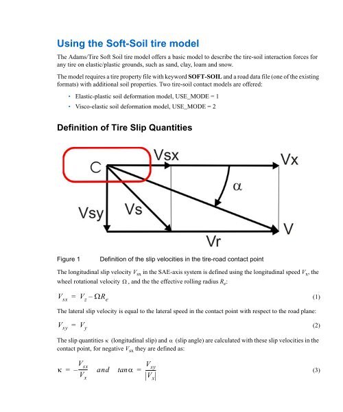
Definition of Tire Slip Quantities<br />
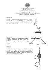
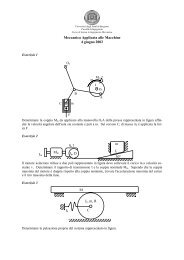
Figure 1<br />
Definition of <strong>the</strong> slip velocities in <strong>the</strong> <strong>tire</strong>-road contact point<br />
The longitudinal slip velocity V sx in <strong>the</strong> SAE-axis system is defined using <strong>the</strong> longitudinal speed V x , <strong>the</strong><br />
wheel rotational velocity and <strong>the</strong> <strong>the</strong> effective rolling radius R e :<br />
V sx = V z – R e<br />
(1)<br />
The lateral slip velocity is equal to <strong>the</strong> lateral speed in <strong>the</strong> contact point with respect to <strong>the</strong> road plane:<br />
V sy<br />
=<br />
V y<br />
(2)<br />
The slip quantities (longitudinal slip) and (slip angle) are calculated with <strong>the</strong>se slip velocities in <strong>the</strong><br />
contact point, for negative V sx <strong>the</strong>y are defined as:<br />
V sx<br />
V x<br />
= –------- and tan<br />
=<br />
V<br />
-------- sy<br />
V x<br />
(3)
2<br />
Adams/Tire<br />
<strong>Using</strong> <strong>the</strong> <strong>Soft</strong>-<strong>Soil</strong> <strong>tire</strong> <strong>model</strong><br />
and for positive V sx (driving) as:<br />
<br />
V sx<br />
V r<br />
= –------- and tan<br />
=<br />
V<br />
------- sy<br />
V r<br />
(4)<br />
V r is <strong>the</strong> rolling speed V r is determined using <strong>the</strong> effective rolling radius R e : (5)<br />
Note that for realistic <strong>tire</strong> forces <strong>the</strong> slip angle is limited to degrees and <strong>the</strong> longitudinal slip <br />
1<br />
to .<br />
90<br />
V r R e <br />
Loaded and Effective Tire Rolling Radius<br />
The loaded rolling <strong>tire</strong> radius R l is defined as <strong>the</strong> unloaded <strong>tire</strong> radius R 0 minus <strong>the</strong> <strong>tire</strong> deflection f 0 due<br />
to <strong>the</strong> vertical load:<br />
R l<br />
R 0 f 0<br />
(6)<br />
The effective rolling radius R e (at free rolling of <strong>the</strong> <strong>tire</strong>), which is used to calculate <strong>the</strong> rotational speed<br />
of <strong>the</strong> <strong>tire</strong>, is defined by:<br />
V<br />
Re<br />
<br />
x<br />
<br />
(7)
<strong>Using</strong> <strong>the</strong> <strong>Soft</strong>-<strong>Soil</strong> <strong>tire</strong> <strong>model</strong><br />
Definition of Tire Slip Quantities<br />
3<br />
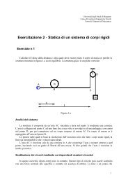
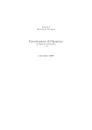
For radial <strong>tire</strong>s, <strong>the</strong> effective rolling radius is ra<strong>the</strong>r independent of load in its load range of operation<br />
because of <strong>the</strong> high stiffness of <strong>the</strong> <strong>tire</strong> belt circumference. Only at low loads does <strong>the</strong> effective <strong>tire</strong> radius<br />
decrease with increasing vertical load due to <strong>the</strong> <strong>tire</strong> tread thickness, see <strong>the</strong> Figure 2.<br />
Figure 2<br />
Effective and loaded <strong>tire</strong> radius as a function of <strong>the</strong> vertical load
4<br />
Adams/Tire<br />
<strong>Using</strong> <strong>the</strong> <strong>Soft</strong>-<strong>Soil</strong> <strong>tire</strong> <strong>model</strong><br />
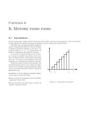
Effective Rolling Radius and Longitudinal Slip<br />
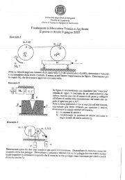
Figure 3<br />
Side view of a rolling <strong>tire</strong><br />
To represent <strong>the</strong> effective rolling radius R e , a PAC2002 compatible equation is used:<br />
R<br />
d<br />
d<br />
e R f0,F<br />
( Deff<br />
atan( Beff<br />
f ) Feff<br />
f<br />
z 0 0<br />
0 0<br />
)<br />
(8)<br />
f<br />
in which ,F is <strong>the</strong> nominal <strong>tire</strong> deflection at <strong>the</strong> nominal <strong>tire</strong> load F z0 :<br />
0 z0<br />
f<br />
0,F<br />
z0 F<br />
C<br />
z0<br />
z<br />
(9)<br />
and<br />
d<br />
f 0<br />
is called <strong>the</strong> dimensionless radial <strong>tire</strong> deflection, defined by:
<strong>Using</strong> <strong>the</strong> <strong>Soft</strong>-<strong>Soil</strong> <strong>tire</strong> <strong>model</strong><br />
Elastic-plastic <strong>tire</strong>-soil contact<br />
5<br />
f<br />
d<br />
0<br />
f<br />
<br />
f<br />
0<br />
0,F z 0<br />
(10)<br />
Elastic-plastic <strong>tire</strong>-soil contact<br />
The interaction forces for a rigid wheel<br />
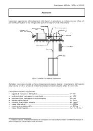
The static sinkage of a rigid object into a soft soil depends on <strong>the</strong> load on that object: Bekker [1]<br />
formulated <strong>the</strong> sinkage h of a flat plate with width b as follows:<br />
p(<br />
h )<br />
( k<br />
c<br />
/ b k<br />
<br />
) h<br />
n<br />
(11)<br />
k<br />
k<br />
in which c and are <strong>the</strong> cohesive and frictional moduli respectively, n <strong>the</strong> sinkage exponent. The<br />
static stress p is in equilibrium with <strong>the</strong> vertical force Fz.<br />
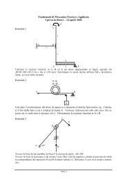
Figure 4<br />
Pressure distribution under a flat plate
6<br />
Adams/Tire<br />
<strong>Using</strong> <strong>the</strong> <strong>Soft</strong>-<strong>Soil</strong> <strong>tire</strong> <strong>model</strong><br />
When applying this approach to a non-rolling wheel <strong>the</strong> static stress distribution can be estimated as<br />
shown in <strong>the</strong> Figure 5<br />
Figure 5<br />
Static stress distribution under a non-rolling rigid wheel<br />
For <strong>the</strong> dynamic sinkage <strong>the</strong> wheel rotational speed must be taken into account.
<strong>Using</strong> <strong>the</strong> <strong>Soft</strong>-<strong>Soil</strong> <strong>tire</strong> <strong>model</strong><br />
Elastic-plastic <strong>tire</strong>-soil contact<br />
7<br />
Figure 6<br />
Wheel entry and exit angle when rolling on soil<br />
<br />
Assume a wheel soil contact with entry angle f and exit angle r , see also [2], <strong>the</strong>n <strong>the</strong>se angles<br />
can be written as a function of <strong>the</strong> total sinkage h and <strong>the</strong> exit penetration h e as follows:<br />
<br />
<br />
<br />
f<br />
r<br />
acos( 1<br />
h / R )<br />
acos( 1<br />
h<br />
e<br />
/ R )<br />
The exit penetration h e depends on <strong>the</strong> elastic stiffness C s of <strong>the</strong> soil.<br />
(12)
8<br />
Adams/Tire<br />
<strong>Using</strong> <strong>the</strong> <strong>Soft</strong>-<strong>Soil</strong> <strong>tire</strong> <strong>model</strong><br />
Based on <strong>the</strong> terramechanical approach as described in [2] <strong>the</strong> normal and shear stresses can be <strong>model</strong>ed<br />
as shown in <strong>the</strong> Figure 7.<br />
Figure 7<br />
Normal and shear stress <strong>model</strong>ling of a rotating wheel<br />
The wheel normal stress distribution can be defined as function of <strong>the</strong> wheel angle [2,3]:<br />
<br />
<br />
for m f :
<strong>Using</strong> <strong>the</strong> <strong>Soft</strong>-<strong>Soil</strong> <strong>tire</strong> <strong>model</strong><br />
Elastic-plastic <strong>tire</strong>-soil contact<br />
9<br />
n<br />
kc<br />
<br />
( ) R0<br />
k<br />
cos( ) cos( <br />
b <br />
<br />
<br />
for<br />
r m<br />
:<br />
<br />
f<br />
)<br />
n<br />
(13)<br />
(<br />
) R<br />
n<br />
0<br />
kc<br />
<br />
b<br />
k<br />
<br />
<br />
<br />
<br />
cos<br />
<br />
<br />
<br />
f<br />
r<br />
<br />
<br />
m<br />
r<br />
( <br />
f<br />
<br />
m<br />
<br />
)<br />
cos( <br />
<br />
f<br />
<br />
) <br />
<br />
n<br />
with b <strong>the</strong> wheel width and R 0 <strong>the</strong> wheel radius.<br />
<br />
The angle m is <strong>the</strong> angle at which <strong>the</strong> maximum normal stress occurs [4]:<br />
<br />
m a0<br />
a1<br />
)<br />
( <br />
f<br />
(14)<br />
The shear stress [5,6] in longitudinal direction is:<br />
( ) ( c (<br />
)tan( ))( 1<br />
e<br />
x x<br />
x<br />
and in lateral direction yields:<br />
j ( ) / k<br />
)<br />
(15)<br />
( ) ( c (<br />
)tan( ))( 1<br />
e<br />
y<br />
jy(<br />
) / k y<br />
)<br />
(16)<br />
In equations 15 and 16 c represents <strong>the</strong> cohesion stress of <strong>the</strong> soil, <strong>the</strong> friction angle of <strong>the</strong> soil and k x<br />
and k y <strong>the</strong> shear deformation moduli. Assuming that <strong>the</strong> wheel has a longitudinal slip , <strong>the</strong> longitudinal<br />
shear displacement along <strong>the</strong> contact area j x in equation 16 can be estimated [5,6] by using <strong>the</strong><br />
longitudinal slip and wheel radius R 0 :<br />
<br />
j ( ) R [ (<br />
1 )(sin( <br />
x<br />
0<br />
f<br />
f<br />
) sin( ))]<br />
(17)<br />
Similar <strong>the</strong> lateral shear displacement j y will depend on <strong>the</strong> slip angle and <strong>the</strong> wheel radius R 0 :<br />
j ( ) R ( 1 )( <br />
y<br />
0<br />
f<br />
)tan( )<br />
(18)
10<br />
Adams/Tire<br />
<strong>Using</strong> <strong>the</strong> <strong>Soft</strong>-<strong>Soil</strong> <strong>tire</strong> <strong>model</strong><br />
Figure 8 illustrates <strong>the</strong> shear stress as a function of soil deformation.<br />
Figure 8 Measured shear stress compared to fitted stress (equation 15)<br />
The longitudinal shear deformation modulus k x is defined as:<br />
k<br />
x<br />
k k 1<br />
x0 x<br />
(19)<br />
and <strong>the</strong> lateral shear deformation modulus k y :<br />
k<br />
y<br />
k k 1<br />
y0 y<br />
Having <strong>the</strong> normal and shear stress for <strong>the</strong> rotating wheel, <strong>the</strong> <strong>tire</strong>-soil interaction contact forces and<br />
moments can be calculated:<br />
• Longitudinal force:
<strong>Using</strong> <strong>the</strong> <strong>Soft</strong>-<strong>Soil</strong> <strong>tire</strong> <strong>model</strong><br />
Elastic-plastic <strong>tire</strong>-soil contact<br />
11<br />
F<br />
x<br />
bR<br />
f<br />
<br />
r<br />
{ ( )cos( ) (<br />
)sin( )}d<br />
x<br />
(20)<br />
• Lateral force:<br />
F<br />
y<br />
f<br />
bR ( )d<br />
r<br />
y<br />
(21)<br />
• Vertical load:<br />
F<br />
z<br />
bR<br />
f<br />
<br />
r<br />
{ ( )sin( ) (<br />
)sin( )}d<br />
x<br />
(22)<br />
• Overturning moment:<br />
M x<br />
0<br />
(23)<br />
• Rolling resistance moment:<br />
M<br />
y<br />
<br />
2<br />
bR <br />
<br />
f<br />
r<br />
0<br />
( )sin( )d<br />
<br />
c<br />
rol<br />
F<br />
z<br />
(24)<br />
with c rol <strong>the</strong> <strong>tire</strong> (internal) rolling resistance coefficient.<br />
• Aligning moment:<br />
M<br />
z<br />
f<br />
2<br />
bR ( )sin( )d<br />
r<br />
y<br />
(25)<br />
Tire deformation<br />
In order to take <strong>the</strong> <strong>tire</strong> deflection into account <strong>the</strong> substitution circle approach is taken as was suggested<br />
by Bekker [7]:
12<br />
Adams/Tire<br />
<strong>Using</strong> <strong>the</strong> <strong>Soft</strong>-<strong>Soil</strong> <strong>tire</strong> <strong>model</strong><br />
Figure 9<br />
Substitution circle to account for <strong>tire</strong> deflection<br />
At a certain penetration of <strong>the</strong> <strong>tire</strong> into <strong>the</strong> soil <strong>the</strong> <strong>tire</strong> deflection and sinkage can be determined by an<br />
iteration process based on <strong>the</strong> fact that <strong>the</strong> vertical <strong>tire</strong> force and <strong>the</strong> force due to <strong>the</strong> sinkage must be<br />
equal.<br />
The <strong>tire</strong> force can be calculated with <strong>the</strong> <strong>tire</strong> stiffness C z and <strong>tire</strong> deflection f 0 by:<br />
F<br />
z,<strong>tire</strong><br />
C<br />
z f 0<br />
(26)<br />
while <strong>the</strong> <strong>tire</strong> sinkage force is defined by equation (22), however, replacing <strong>the</strong> unloaded <strong>tire</strong> radius R 0<br />
by <strong>the</strong> radius of <strong>the</strong> substitution circle R*.<br />
Bekker [7] derived following relation in between <strong>the</strong> <strong>tire</strong> deflection f 0 and <strong>tire</strong> sinkage h:
<strong>Using</strong> <strong>the</strong> <strong>Soft</strong>-<strong>Soil</strong> <strong>tire</strong> <strong>model</strong><br />
Elastic-plastic <strong>tire</strong>-soil contact<br />
13<br />
*<br />
R<br />
f0<br />
1<br />
<br />
h<br />
f<br />
h<br />
R 0<br />
0<br />
<br />
(27)<br />
Elastic and Plastic deformation<br />
Depending on <strong>the</strong> soil properties one part of <strong>the</strong> deformation is elastic and <strong>the</strong> remaining part is nonirreversible<br />
(plastic deformation). The elastic deformation is calculated with by <strong>the</strong> soil stiffness C s at <strong>the</strong><br />
maximum normal stress max :<br />
(<br />
<br />
he<br />
<br />
C<br />
m<br />
s<br />
)<br />
(28)<br />
Multi-pass effect<br />
When a <strong>tire</strong> has passed a certain spot of soil, a second <strong>tire</strong> will experience different soil properties when<br />
rolling over that spot due to <strong>the</strong> plastic deformation of <strong>the</strong> soil by <strong>the</strong> first <strong>tire</strong>.<br />
Therefore this <strong>Soft</strong> <strong>Soil</strong> <strong>tire</strong> <strong>model</strong> stores <strong>the</strong> elastic and plastic deformation of each <strong>tire</strong> as a function of<br />
<strong>the</strong> contact point x,y coordinates. When a <strong>tire</strong> passes a point with plastic deformation caused by a<br />
previous <strong>tire</strong>, <strong>the</strong> normal pressure calculation will account for <strong>the</strong> plastic deformation history.<br />
Figure 10 explains <strong>the</strong> mechanism applied in this <strong>tire</strong> <strong>model</strong> [8]:<br />
Assume two <strong>tire</strong>s rolling after each o<strong>the</strong>r over <strong>the</strong> same spot of soil. The first <strong>tire</strong> will have a total<br />
deformation h 1 existing of a plastic part h p1 and an elastic part h e1 . When a second <strong>tire</strong> passes <strong>the</strong> same<br />
spot, <strong>the</strong> soil will first have an elastic deformation from A to B (= h e1 ) and <strong>the</strong>n continue to follow <strong>the</strong><br />
normal pressure characteristic to point C. The plastic deformation of <strong>the</strong> second <strong>tire</strong> h p2 will be equal to<br />
<strong>the</strong> total deformation h 2 subtracted with <strong>the</strong> elastic deformation h e2 .
14<br />
Adams/Tire<br />
<strong>Using</strong> <strong>the</strong> <strong>Soft</strong>-<strong>Soil</strong> <strong>tire</strong> <strong>model</strong><br />
Figure 10<br />
Normal pressure characteristic for multi-pass approach<br />
Note:<br />
The <strong>tire</strong> <strong>model</strong> stores <strong>the</strong> x, y coordinates, <strong>the</strong> elastic and plastic deformation and <strong>tire</strong> width<br />
of each <strong>tire</strong>. Because of <strong>the</strong> one-point of contact approach used in this <strong>Soft</strong>-<strong>Soil</strong> <strong>tire</strong> <strong>model</strong>,<br />
<strong>the</strong> total stored plastic deformation will be applied for a next <strong>tire</strong> when its contact point<br />
comes into <strong>the</strong> rut of a previous <strong>tire</strong>.<br />
Visco-elastic <strong>tire</strong>-soil contact<br />
Next to elastic-plastic deformation <strong>model</strong>s for soft soil, also visco-elastic <strong>model</strong>ing approaches exist.<br />
Wanjii e.o. [9] derived a visco-elastic <strong>model</strong> for <strong>the</strong> normal stress along <strong>the</strong> contact line in between <strong>the</strong><br />
<strong>tire</strong> and <strong>the</strong> soil. A three element Maxwell approach is used for a rigid wheel, see Figure 11.
<strong>Using</strong> <strong>the</strong> <strong>Soft</strong>-<strong>Soil</strong> <strong>tire</strong> <strong>model</strong><br />
Visco-elastic <strong>tire</strong>-soil contact<br />
15<br />
Figure 11<br />
Three element Maxwell <strong>model</strong> for a rigid wheel on visco-elastic soil<br />
For this <strong>model</strong> <strong>the</strong> normal stress in <strong>the</strong> contact in between <strong>tire</strong> and ground is:<br />
x <br />
<br />
A x <br />
G1<br />
2 2 G2VxTr<br />
V T <br />
( x ) ( xA<br />
x ) (<br />
xA<br />
VxTr<br />
) 1<br />
e<br />
x r<br />
xA<br />
2R0<br />
R0<br />
<br />
<br />
<br />
x<br />
<br />
(29)<br />
With<br />
x<br />
a<br />
R<br />
0<br />
)<br />
sin( <br />
f<br />
)<br />
x<br />
R<br />
sin( <br />
0<br />
2<br />
T r /<br />
G<br />
In which<br />
T r is <strong>the</strong> relaxation time<br />
<br />
is <strong>the</strong> viscosity of <strong>the</strong> soil
16<br />
Adams/Tire<br />
<strong>Using</strong> <strong>the</strong> <strong>Soft</strong>-<strong>Soil</strong> <strong>tire</strong> <strong>model</strong><br />
V x is <strong>the</strong> forward velocity of <strong>the</strong> <strong>tire</strong><br />
G 1 is <strong>the</strong> first elastic modulus<br />
G 2 is <strong>the</strong> second elastic modulus<br />
The longitudinal and lateral shear stresses are calculated using <strong>the</strong> equations 15 until and including 19 as<br />
used for <strong>the</strong> elastic-plastic <strong>tire</strong>-soil <strong>model</strong>. Similar for <strong>the</strong> <strong>tire</strong>-ground interaction forces equation (20 -<br />
24) are used.<br />
For <strong>the</strong> multi-pass effect, <strong>the</strong> road deformation at <strong>the</strong> exit of <strong>the</strong> <strong>tire</strong>-soil contact (point B) and <strong>the</strong> time<br />
of deformation occurrence is stored. When a second <strong>tire</strong> passes <strong>the</strong> same spot, <strong>the</strong> road deformation<br />
corrected with <strong>the</strong> relaxation effect is taken to correct <strong>the</strong> road height input.<br />
References:<br />
1. Bekker, M.G., Off-<strong>the</strong>-road-locomotion, Ann Arbor, The University of Michigan Press, 1960.<br />
2. G. Ishigami, A. Miwa, K. Nagatani, K. Yoshida, Terramechanics - Based Model for Steering<br />
Maneuver of Planetary Exploration Rovers on Loose <strong>Soil</strong>, Journal of Field robotics 24(3), 233-<br />
250 (2007), Wiley Periodicals, Inc.<br />
3. Yoshida, K., Watanabe, T., Mizuna, N., Ishigami, G., Terramechanics - based analysis and<br />
traction control of a lunar/planetary rover. In Proceedings of <strong>the</strong> Int. Conf. Of Field and Service<br />
Robotics (FSR '03), Yamanashi, Japan.<br />
4. Wong, J.Y., Reece, A., Prediction of rigid wheel performance based on <strong>the</strong> analysis of soil-wheel<br />
stresses part I, performance driving rigid wheels, Journal of Terramechanics, 4, 81-98.<br />
5. Janosi, Z. Hanamoto, B., The analytical determination of drawbar pull as a function of slip for<br />
tracked vehicle in deformable soils, In proceedings of <strong>the</strong> 1 st Int. conf. on Terrain-Vehicle<br />
systems, Torino, Italy.<br />
6. Wong, J.Y., Theory of Ground Vehicles, John Wiley & Sons, Inc., second edition, 1993.<br />
7. Bekker, M.G., Introduction to terrain-vehicle systems, Ann Arbor, The University of Michigan<br />
Press, 1969.<br />
8. AS 2 TM User's Guide, version 1.12, AESCO GbR, Hamburg.<br />
9. S. Wanjii, T. Hiroma, Y. Ota, T. Kataoka, Predicition of Wheel Performance by Analysis of<br />
Normal and Tangential Stress Distributions under <strong>the</strong> Wheel-<strong>Soil</strong> Interface, Journal of<br />
Terramechanics, Vol. 34, No. 3, pp. 165-186, 1997.<br />
10. Schmid, I.C., Interaction of Vehicle and Terrain Results from 10 Years Research at IKK, Journal<br />
of Terramechanics, Vol. 32, No. 1, pp. 3-26, 1995.<br />
11. Schmid, I.C., Aubel, Th., Der elastische Reifen auf nachgiebiger Fahrbahn - Rechen<strong>model</strong>l im<br />
Hinblick auf Reifendruckregelung, VDI Berichte nr. 916, 1991.<br />
12. Faßbender, F., Simulation der Vertikaldynamik von Fahrzeugen auf Geländeböden mit STINA -<br />
SOIL TIRE INTERFACE TO ADAMS einem Zusatzmodul für das Mehrkörperprogramm<br />
ADAMS. Number 521 in Fortschritt-Berichte VDI Reihe 12. VDI Verlag, Düsseldorf, 2002.<br />
Dissertation Universität der Bundeswehr Hamburg.
<strong>Using</strong> <strong>the</strong> <strong>Soft</strong>-<strong>Soil</strong> <strong>tire</strong> <strong>model</strong><br />
Feature and property overview of <strong>the</strong> Adams/Tire <strong>Soft</strong> <strong>Soil</strong> Tire <strong>model</strong><br />
17<br />
Feature and property overview of <strong>the</strong> Adams/Tire <strong>Soft</strong> <strong>Soil</strong> Tire<br />
<strong>model</strong><br />
• Two <strong>tire</strong>-road contact <strong>model</strong>s:<br />
• Elastic-plastic contact <strong>model</strong><br />
elastic <strong>tire</strong>: <strong>tire</strong> deflection is taken into account<br />
multi-pass effect: road plastic deformation history is stored and taken into account when<br />
ano<strong>the</strong>r <strong>tire</strong> passes <strong>the</strong> same spot<br />
• Visco-elastic contact <strong>model</strong><br />
rigid <strong>tire</strong>: no <strong>tire</strong> deflection<br />
multi-pass effect: road viscous deformation is stored. The stored deformation reduced by <strong>the</strong><br />
relaxation effect is taken into account when ano<strong>the</strong>r <strong>tire</strong> passes <strong>the</strong> same spot<br />
• Tire effective rolling radius is defined similar to pac2002 <strong>tire</strong> <strong>model</strong><br />
• Tire properties are very basic (<strong>tire</strong> vertical stiffness and damping, unloaded radius, width and<br />
effective rolling radius parameters)<br />
• The existing Adams/Tire roads can be used, just an additional section with <strong>the</strong> soil properties is<br />
required. These soil properties are valid for <strong>the</strong> whole road.<br />
<br />
• Linearization of - F x characteristic during q-statics to ensure robust q-statics<br />
• Linear vertical <strong>tire</strong> stiffness can be replaced by a (non-linear) deflection-load curve<br />
• Scaling factors of road friction, <strong>tire</strong> cornering and longitudinal stiffness' are supported<br />
• SMP (multi-thread, C++ solver) is supported<br />
• Tire-road contact is a one-point contact<br />
• Camber effects are not taken into account<br />
• Overturning moment is not calculated<br />
• No bulldozing effects<br />
Example of <strong>the</strong> <strong>tire</strong> property file for <strong>the</strong> <strong>Soft</strong>-<strong>Soil</strong> Tire <strong>model</strong>:<br />
$----------------------------------------------------------MDI_HEADER<br />
[MDI_HEADER]<br />
FILE_TYPE = 'tir'<br />
FILE_VERSION = 2.0<br />
FILE_FORMAT = 'ASCII'<br />
(COMMENTS)<br />
{comment_string}<br />
'Tire - XXXXXX'<br />
'Pressure - XXXXXX'<br />
'Test Date - XXXXXX'<br />
'Test <strong>tire</strong>'<br />
'New File Format v2.1'<br />
$---------------------------------------------------------------units
18<br />
Adams/Tire<br />
<strong>Using</strong> <strong>the</strong> <strong>Soft</strong>-<strong>Soil</strong> <strong>tire</strong> <strong>model</strong><br />
[UNITS]<br />
LENGTH<br />
= 'mm'<br />
FORCE<br />
= 'newton'<br />
ANGLE<br />
= 'degree'<br />
MASS<br />
= 'kg'<br />
TIME<br />
= 'sec'<br />
$---------------------------------------------------------------<strong>model</strong><br />
! use mode 1 2<br />
! --------------------------------------------------------------<br />
! flexible wheel/<strong>tire</strong> with elastic-plastic road X<br />
! rigid wheel/<strong>tire</strong> with visco-elastic road X<br />
!<br />
PROPERTY_FILE_FORMAT = 'SOFT-SOIL'<br />
USE_MODE = 1.0<br />
$-----------------------------------------------------------dimension<br />
[DIMENSION]<br />
UNLOADED_RADIUS = 309.9<br />
WIDTH = 235.0<br />
ASPECT_RATIO = 0.45<br />
$-----------------------------------------------------------parameter<br />
[PARAMETER]<br />
NOMINAL_TIRE_LOAD = 4000<br />
VERTICAL_STIFFNESS = 310.0<br />
VERTICAL_DAMPING = 0.5<br />
ROLLING_RESISTANCE = 0.01<br />
BREFF = 8.4<br />
DREFF = 0.27<br />
FREFF = 0.07<br />
$---------------------------------------------------------------shape<br />
[SHAPE]<br />
{radial width}<br />
1.0 0.0<br />
1.0 0.2<br />
1.0 0.4<br />
1.0 0.5<br />
1.0 0.6<br />
1.0 0.7<br />
1.0 0.8<br />
1.0 0.85<br />
1.0 0.9<br />
0.9 1.0<br />
$----------------------------------------------------------load_curve<br />
$ For a non-linear <strong>tire</strong> vertical stiffness<br />
$ Maximum of 100 points<br />
[DEFLECTION_LOAD_CURVE]<br />
{pen fz}<br />
0 0.0<br />
1.0 212.0<br />
2.0 428.0<br />
3.0 648.0<br />
5.0 1100.0<br />
10.0 2300.0<br />
20.0 5000.0<br />
30.0 8100.0
<strong>Using</strong> <strong>the</strong> <strong>Soft</strong>-<strong>Soil</strong> <strong>tire</strong> <strong>model</strong><br />
Example of <strong>the</strong> required <strong>Soil</strong> properties in <strong>the</strong> Road Data File:<br />
19<br />
Example of <strong>the</strong> required <strong>Soil</strong> properties in <strong>the</strong> Road Data File:<br />
Existing road data files can be used, but a 'SOIL_PROPERTIES' section has to be added:<br />
$-----------------------------------------------------SOIL_PROPERTIES<br />
[SOIL_PROPERTIES]<br />
FRICTION_ANGLE = 37.2 $units: degree<br />
COHESION_STRESS = 8.0E-4 $units: N/mm**2<br />
SOIL_DEFORM_MOD_KX0 = 43.0 $units: mm<br />
SOIL_DEFORM_MOD_KX1 = 0.6283 $units: mm/deg<br />
SOIL_DEFORM_MOD_KY0 = 20.0 $units: mm<br />
SOIL_DEFORM_MOD_KY1 = 0.2269 $units: mm/deg<br />
!visco-elastic <strong>tire</strong>:<br />
ELASTIC_MODULUS_G1 = 0.071E-3 $units: N/mm**3<br />
ELASTIC_MODULUS_G2 = 1.072E-3 $units: N/mm**3<br />
SOIL_VISCOSITY = 7.14E-3 $units: Ns/mm**3<br />
!plastic-elastic <strong>tire</strong>:<br />
PRESSURE_SINKAGE_KC = 1.37E-3 $units: N/mm**(n+1)<br />
PRESSURE_SINKAGE_KFI = 8.14E-4 $units: N/mm**(n+2)<br />
SINKAGE_EXPONENT = 1 $units: = n<br />
SOIL_INTERACTION_A0 = 0.4 $units: -<br />
SOIL_INTERACTION_A1 = 0.15 $units: -<br />
SOIL_STIFFNESS = 8.14E-3 $units: N/mm**3<br />
Symbols<br />
B eff<br />
b<br />
c<br />
c rol<br />
D eff<br />
C z<br />
C s<br />
f 0<br />
effective rolling radius factor<br />
<strong>tire</strong>/wheel width<br />
cohesion<br />
<strong>tire</strong> rolling resistance coefficient<br />
effective rolling radius factor<br />
<strong>tire</strong> vertical stiffness<br />
soil stiffness<br />
<strong>tire</strong> deflection<br />
d<br />
dimensionless <strong>tire</strong> deflection<br />
f 0<br />
f0,F<br />
z 0<br />
G 1<br />
G 2<br />
F eff<br />
F x<br />
nominal <strong>tire</strong> deflection<br />
elastic modulus<br />
elastic modulus<br />
effective rolling radius factor<br />
longitudinal force
20<br />
Adams/Tire<br />
<strong>Using</strong> <strong>the</strong> <strong>Soft</strong>-<strong>Soil</strong> <strong>tire</strong> <strong>model</strong><br />
F y<br />
F z<br />
F z0<br />
h<br />
h e<br />
h p<br />
k c<br />
k <br />
lateral force<br />
vertical load<br />
nominal <strong>tire</strong> load<br />
sinkage<br />
elastic deformation<br />
plastic deformation<br />
cohesive modulus<br />
frictional modulus<br />
k x soil deformation modulus<br />
k y soil deformation modulus<br />
M x overturning moment<br />
M y rolling resistance moment<br />
M z aligning moment<br />
n sinkage component<br />
p static stress<br />
R e effective rolling radius<br />
R 0 unloaded (free) <strong>tire</strong>/wheel radius<br />
R l <strong>tire</strong> loaded radius<br />
R* radius of substitution circle<br />
T r relaxation time<br />
V total <strong>tire</strong>/wheel speed<br />
V r <strong>tire</strong> rolling velocity<br />
V x <strong>tire</strong>/wheel forward speed (parallel to wheel plane)<br />
V sx longitudinal slip speed<br />
V sy lateral slip speed<br />
<br />
<br />
<br />
<br />
<br />
slip angle<br />
longitudinal slip<br />
friction angle<br />
normal stress<br />
<strong>tire</strong>/wheel rotational speed
<strong>Using</strong> <strong>the</strong> <strong>Soft</strong>-<strong>Soil</strong> <strong>tire</strong> <strong>model</strong><br />
Symbols<br />
21<br />
x<br />
y<br />
<br />
f<br />
r<br />
<br />
longitudinal shear stress<br />
lateral shear stress<br />
wheel angle<br />
wheel soil entry angle<br />
wheel soil entry angle<br />
viscosity of <strong>the</strong> soil
22<br />
Adams/Tire<br />
<strong>Using</strong> <strong>the</strong> <strong>Soft</strong>-<strong>Soil</strong> <strong>tire</strong> <strong>model</strong>