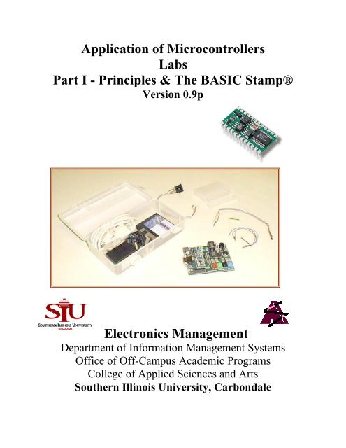
Application of Microcontrollers Labs Part I - Principles & The ... - ISL
Application of Microcontrollers Labs Part I - Principles & The ... - ISL
Application of Microcontrollers Labs Part I - Principles & The ... - ISL

You also want an ePaper? Increase the reach of your titles
YUMPU automatically turns print PDFs into web optimized ePapers that Google loves.
<strong>Application</strong> <strong>of</strong> <strong>Microcontrollers</strong><br />
<strong>Labs</strong><br />
<strong>Part</strong> I - <strong>Principles</strong> & <strong>The</strong> BASIC Stamp®<br />
Version 0.9p<br />
Electronics Management<br />
Department <strong>of</strong> Information Management Systems<br />
Office <strong>of</strong> Off-Campus Academic Programs<br />
College <strong>of</strong> Applied Sciences and Arts<br />
Southern Illinois University, Carbondale
Microcontroller <strong>Labs</strong> - <strong>Part</strong> I (V0.9p)<br />
This document is the accompanying labs for the <strong>Application</strong> <strong>of</strong> <strong>Microcontrollers</strong> Manual. If you<br />
do not have the manual, please visit the Parallax Stamp-in-Class web site.<br />
Note to instructors:<br />
<strong>The</strong>re is an accompanying version with answers. <strong>The</strong>se labs are currently the same being used in<br />
the SIUC ELM program. Distribution <strong>of</strong> the Instructor version will be very limited at this time.<br />
Contact Martin Hebel if you require help or see about an instructor's version.<br />
2
Microcontroller <strong>Labs</strong> - <strong>Part</strong> I (V0.9p)<br />
<strong>Application</strong> <strong>of</strong> <strong>Microcontrollers</strong><br />
Copyright Notices<br />
Copyright 1999, Board <strong>of</strong> Trustees, Southern Illinois University. <strong>The</strong> manual and labs may be copied and<br />
distributed freely in its entirety in electronic format by individuals for educational non-pr<strong>of</strong>it use.<br />
Distribution <strong>of</strong> printed material is authorized for educational non-pr<strong>of</strong>it use. Other distribution venues,<br />
including mass electronic distribution via the Internet, require the written approval <strong>of</strong> the SIU Board <strong>of</strong><br />
Trustees.<br />
BASIC Stamp® is a registered trademark <strong>of</strong> Parallax, Inc. Images and drawings are reproduced by<br />
permission <strong>of</strong> Parallax, Inc.<br />
UMPS® is a registered trademark <strong>of</strong> Virtual Micro Design. UMPS images are reproduced by permission<br />
<strong>of</strong> Virtual Micro Design.<br />
Disclaimer<br />
Southern Illinois University, the manual developers, and approved distributors will not be held liable for<br />
any damages or losses incurred through the use <strong>of</strong> the manual, labs and associated materials developed at<br />
Southern Illinois University.<br />
Contact Information<br />
E-mail:<br />
Primary developer <strong>of</strong> the manual and labs:<br />
Martin Hebel ....................................................................................................... mhebel@siu.edu<br />
Contributing developer and editor:<br />
Will Devenport.................................................................................................... willd@siu.edu<br />
Director, Off-Campus Academic Programs:<br />
Dr. Terry Bowman............................................................................................... tbowman@siu.edu<br />
Chair, Department <strong>of</strong> Information Management Systems:<br />
Dr. Jan Schoen Henry .......................................................................................... jshenry@siu.edu<br />
Mailing:<br />
Electronics Management<br />
MC: 6614<br />
College <strong>of</strong> Applied Sciences and Arts<br />
Southern Illinois University, Carbondale<br />
Carbondale, IL 62901-6614<br />
A product such as this is not done alone. <strong>The</strong> following people are thanked for their<br />
contributions: Ken Gracey and the gang at Parallax for their work on making this possible for<br />
our students; Philippe Techer at Virtual Micro Design for designing a great simulation package<br />
and working with us; Myke Predko for his feedback and recommendation; I. Scott MacKenzie<br />
for a concise text on the 8051; our student evaluators John Almy and Kirk Larsen for catching<br />
many mistakes and for contextual recommendations; and finally Terry Bowman and Jan Henry<br />
for budgeting the endeavor and wanting the best education for our students.<br />
3
Microcontroller <strong>Labs</strong> - <strong>Part</strong> I (V0.9p)<br />
Key Web Sites:<br />
Electronics Management Home Page: ................................. www.siu.edu/~imsasa/elm<br />
Off-Campus Programs Home Page: .................................... http://131.230.64.6/<br />
Parallax Incorporated Home Page: ...................................... www.parallaxinc.com<br />
...................................... www.stampsinclass.com<br />
Virtual Micro Design Home Page (UMPS): ........................ www.vmdesign.com<br />
Distributors & Additional Information:<br />
Digi-Key Electronics - Stamps, components ....................... www.digikey.com<br />
Jameco Electronics - Stamps, components .......................... www.jameco.com<br />
JDR Electronics - Stamps, components ............................... www.jdr.com<br />
Wirz Electronics - UMPS U.S. Sales................................... www.wirz.com<br />
Peter H. Anderson - General microcontroller information ... www.phanderson.com<br />
SelmaWare Solutions - Specialized interfacing s<strong>of</strong>tware ..... www.selmaware.com<br />
Texts:<br />
<strong>The</strong> 8051 Microcontroller, 3 rd ed. 1999, Scott MacKenzie. Prentice-Hall<br />
ISBN: 0-13-780008-8<br />
Handbook <strong>of</strong> <strong>Microcontrollers</strong>. 1999, Myke Predko. McGraw-Hill<br />
ISBN: 0-07-913716-4<br />
Programming and Customizing the 8051 Microcontroller. 1999, Myke Predko. McGraw-Hill.<br />
ISBN: 0-07-134192-7<br />
<strong>The</strong> Microcontroller Idea Book. 1994, Jan Axelson. Lakeview Research.<br />
ISBN: 096508190-7<br />
4
Microcontroller <strong>Labs</strong> - <strong>Part</strong> I (V0.9p)<br />
Table <strong>of</strong> Contents<br />
Introduction: Programming the BS2............................................................................................6<br />
File Installation ...................................................................................................................6<br />
Using Stampw.exe...............................................................................................................6<br />
Lab A - Introduction to the BASIC Stamp.................................................................................10<br />
Lab B - <strong>The</strong> Stamp Activity Board & Basic I/O ........................................................................12<br />
Lab C - Binary Numbers ...........................................................................................................14<br />
Lab D - Analog Inputs and Outputs...........................................................................................16<br />
Lab E - Process Control ............................................................................................................21<br />
Lab F - Hexadecimal & BS2 Memory.......................................................................................25<br />
Lab G - Logic Operators and Signed Numbers ..........................................................................27<br />
Lab H - Digital Communications ..............................................................................................29<br />
5
Microcontroller <strong>Labs</strong> - <strong>Part</strong> I (V0.9p)<br />
Introduction: Programming the BS2<br />
Using the Stampw.exe program under Windows is fairly simple. Programs are written and<br />
downloaded to the BS2 on the Activity Board via a serial cable connected to COM 1 or COM 2<br />
serial port <strong>of</strong> the computer. This manual will assume a degree <strong>of</strong> familiarity using Windows<br />
application programs.<br />
File Installation<br />
Unzip the amprog.zip file. It will contain the entire sample BS2 program files for the manual and<br />
labs.<br />
Using Stampw.exe<br />
1) Connect the Basic Stamp 2 (BS2) to the computer with the provided serial cable. If the only<br />
open COM port you have is a DB25 (25 pin) vice a DB9 (9 pin) you will need to use an<br />
adapter available at most computer stores or Radio Shack.<br />
2) Provide power to the Activity Board with the provided power supply wall transformer.<br />
Damage may occur to the Activity Board and Stamp if you use a power supply not provided<br />
with the kit.<br />
3) Locate and run the stampw.exe program using Windows Explorer. <strong>The</strong> following explains<br />
the toolbar buttons and basic operation <strong>of</strong> the program.<br />
Standard File and Printing Tools:<br />
New Document | Open File | Close File | Save | Print<br />
Standard Editing Tools:<br />
Cut | Copy | Paste | Find<br />
6
Microcontroller <strong>Labs</strong> - <strong>Part</strong> I (V0.9p)<br />
Preferences:<br />
This tool can be used to set up preferences such as editor background color, font color, etc. It<br />
can also define the COM port on which the BS2 is connected under 'Editor Operation'. Normally<br />
stampw.exe will auto detect the BS2 on Com 1 or 2. If your computer is configured to another<br />
port for the BS2, it may be defined here.<br />
Identify:<br />
This allows the programmer to verify the BS2 is found and recognized by stampw.exe.<br />
4) Click the Identify button. A message will be returned indicating the BS2 was found, or that<br />
there was a problem communicating with the BS2. If a problem occurred, try to resolve prior<br />
to continuing.<br />
Syntax Check:<br />
Prior to the entered program being downloaded to the BS2, a syntax check is performed <strong>of</strong> the<br />
program. <strong>The</strong> programmer may use this tool to force a syntax check. <strong>The</strong> BS2 does NOT need<br />
to be connected to syntax check programs.<br />
Memory Map:<br />
This tool will open the memory map window. It displays memory (EEPROM and RAM) usage<br />
<strong>of</strong> the program in the editing area will utilize.<br />
Run:<br />
This button will perform the following:<br />
• Perform a syntax check on the program in the editor window.<br />
• Tokenize the program.<br />
• Transfer the program to the BS2 memory.<br />
• Execute the program on the BS2.<br />
Debug:<br />
<strong>The</strong> Debug window is primarily used for DEBUG commands in a BS2 program to send<br />
information back to the host computer. This window will open automatically anytime a program<br />
downloaded to the BS2 contains a Debug instruction. Clicking the tool will also open it. <strong>The</strong><br />
COM port the BS2 is connected to will need to be set following a manual opening<br />
NOTE: Due to an application quirk, the debug window can be 'lost' by having it open and<br />
clicking on another open window, such as the editor. <strong>The</strong> window is not able to seen again until<br />
the stamp2.exe program closes and re-opens. It is HIGHLY RECOMMENDED this window is<br />
maximized the first time it is used to minimize the chance <strong>of</strong> this problem arising.<br />
Help:<br />
<strong>The</strong> help files will eventually bring up Help files for stampw.exe. It is not implemented on the<br />
current version(s). Newer releases may be download from Parallax at www.parallaxinc.com.<br />
7
Microcontroller <strong>Labs</strong> - <strong>Part</strong> I (V0.9p)<br />
Program Tabs:<br />
<strong>The</strong>se tabs indicate all open BS2 programs. A maximum <strong>of</strong> 16 programs can be open for editing<br />
at any one time. A new tab is created any time a new program is started or a program is opened.<br />
All tools work on the active program.<br />
5) Connect one <strong>of</strong> the provided jumpers between the Analog Input and Pin 1 (the left-most pin)<br />
<strong>of</strong> X2 as shown:<br />
6) Open (File à Open, or use the toolbar button) the program AB-Test.bs2.<br />
7) Run this program using the button on the toolbar. Stampw.exe will tokenize the program and<br />
show indication it is transferring the program to the BS2.<br />
8) <strong>The</strong> debug window will appear. Follow the directions in the debug window. AB-Test will<br />
perform a test <strong>of</strong> several features <strong>of</strong> the board to ensure proper operation <strong>of</strong> inputs and<br />
outputs. If any <strong>of</strong> the tests do not work correctly, attempt to resolve the problem and test<br />
again. Contact your instructor or coordinator if it cannot be resolved.<br />
9) Close the debug window.<br />
10) Disconnect the BS2 Activity Board from the computer leaving power connected. Press the<br />
RESET button the Activity board. <strong>The</strong> CHARGE! tune should play. <strong>The</strong> program is still in<br />
BS2 memory though it cannot communicate to the host computer.<br />
11) Disconnect the Stamp from power. Wait approximately one minute. Reconnect power.<br />
Press RESET again. <strong>The</strong> program should still be in memory.<br />
8
Microcontroller <strong>Labs</strong> - <strong>Part</strong> I (V0.9p)<br />
12) Reconnect the BS2 to the computer.<br />
13) Remove the ADC in jumper.<br />
14) Open a NEW editing window by clicking the File button. Enter the following code:<br />
X var byte<br />
FOR X = 1 to 20<br />
FREQOUT 11, 100, 2500<br />
PAUSE 20 - X * 20<br />
NEXT<br />
FREQOUT 11, 500, 3000<br />
END<br />
15) Run the program using the toolbar button.<br />
It's gonna blow!!!!!!! Kidding. But see how easy it is to program Now on to your labs!<br />
9
Microcontroller <strong>Labs</strong> - <strong>Part</strong> I (V0.9p)<br />
Lab A - Introduction to the BASIC Stamp<br />
References:<br />
A. <strong>Application</strong> <strong>of</strong> <strong>Microcontrollers</strong> Manual. 1999, Southern Illinois University.<br />
B. BASIC Stamp Manual, Version 1.9. 1998. Parallax, Inc.<br />
Objectives:<br />
1) Discuss the primary differences between microcontrollers and microprocessors<br />
2) Discuss the difference between processor machine languages and high level languages.<br />
3) Discuss the differences between interpreted and compiled languages.<br />
4) List the ROM, RAM and I/O resources available on the BASIC Stamp II.<br />
5) Develop flowcharts for operations.<br />
• Read Section A <strong>of</strong> Reference A.<br />
• Refer to Reference B to clarify or expand on Reference A material as needed.<br />
______________________________________________________________________________<br />
1. (1 pt) A ___________________ has designed into it RAM, ROM and I/O lines.<br />
2. (2 pts) <strong>The</strong> PIC16C57 has ________ bytes <strong>of</strong> ROM and ________ bytes <strong>of</strong> RAM available<br />
in it.<br />
3. (2 pts) <strong>The</strong> PIC16C57 has _______ Input-Output (I/O) pins or lines, <strong>of</strong> which ____ <strong>of</strong> these<br />
are available to the BS2 programmer.<br />
4. (2 pts) Why are high-level languages independent <strong>of</strong> the processor being written for<br />
5. (1 pt) Symbols which are representative <strong>of</strong> high-level language code and decoded by an<br />
interpreter are known as ________________.<br />
6. (1 pt) <strong>The</strong> Language that is used to program the BS2 is called _____________.<br />
7. (1 pt) <strong>The</strong> ________ on the PIC16C57 is used to hold the PBSASIC2 interpreter on the BS2.<br />
8. (1 pt) Where are programs downloaded stored on the BS2<br />
10
Microcontroller <strong>Labs</strong> - <strong>Part</strong> I (V0.9p)<br />
9. (2 pt) Four I/O pins or lines <strong>of</strong> the PIC16C57 are not usable to the BS2 programmer. What<br />
are these four lines used for<br />
10. (7 pt) Draw a flowchart for cooking spaghetti noodles. Some <strong>of</strong> the steps you will want to<br />
include are:<br />
• Heating water<br />
• Waiting for water to boil<br />
• Adding noodles<br />
• Testing firmness <strong>of</strong> noodles<br />
• Draining noodles<br />
11
Microcontroller <strong>Labs</strong> - <strong>Part</strong> I (V0.9p)<br />
Lab B - <strong>The</strong> Stamp Activity Board & Basic I/O<br />
References:<br />
A. <strong>Application</strong> <strong>of</strong> <strong>Microcontrollers</strong> Manual. 1999, Southern Illinois University.<br />
B. BASIC Stamp Manual, Version 1.9. 1998. Parallax, Inc.<br />
Objectives:<br />
1) List the I/O devices available on the Activity Board.<br />
2) Identify the BS2 pin numbers associated with each I/O.<br />
3) Discuss terminology and respective voltages associated with digital I/O.<br />
4) Write PBASIC2 code to read and write to simple I/O.<br />
5) Use PBASIC2 commands to control the Activity Board speaker.<br />
6) Discuss the need for debouncing input devices.<br />
7) Write PBASIC2 code for debouncing buttons.<br />
• Read Section B <strong>of</strong> Reference A.<br />
• Run programs and sample code.<br />
• Refer to Reference B to clarify or expand on Reference A material as needed.<br />
_____________________________________________________________________________<br />
1. (5 pts) List the BS2 I/O pin numbers for the listed Activity Board devices. <strong>The</strong> first one is<br />
done for you:<br />
<strong>The</strong> blue (right-most) pushbutton ................ P8<br />
<strong>The</strong> red (left-most) pushbutton..................... ___<br />
<strong>The</strong> speaker ................................................. ___<br />
<strong>The</strong> A/D converter Dataout line ................... ___<br />
<strong>The</strong> potentiometer........................................ ___<br />
2. (1 pt) A digital I/O which is HIGH is also referred to as _________ as if it were an on-<strong>of</strong>f<br />
switch, and ______ for its binary representation.<br />
3. (1 pt) LEDs on the Activity Board require a _____ output level to light them. Pushbuttons<br />
which are not depressed are represented by a ______ input level.<br />
4. (2 pts) Write code that would turn on (light) the LED associated with the Black button.<br />
12
Microcontroller <strong>Labs</strong> - <strong>Part</strong> I (V0.9p)<br />
5. (3 pts) Write code that would produce a 2300 Hz frequency from the speaker for 1.5<br />
seconds.<br />
6. Program the following code into the BS2.<br />
INPUT 8<br />
DIR10 = 1<br />
Loop:<br />
IF IN8 = 0 THEN ToggleMe<br />
GOTO Loop<br />
ToggleMe:<br />
TOGGLE 10<br />
GOTO Loop<br />
7. (2 pts) With the program from question 6 running, depress the blue pushbutton 10 times.<br />
What effect does it have Is it consistent Why or why not<br />
8. (4 pts) Change the program in question 6 to use the Button command. Structure it so that it<br />
provides a delay <strong>of</strong> 250 and repeats at a rate <strong>of</strong> 150. For the bytevariable, name it BtnPress.<br />
Test your program.<br />
9. (1 pt) Connect a voltmeter so that the negative lead is on GND <strong>of</strong> the I/O pin header and the<br />
positive lead is on P10 for the BS2 on the I/O pin header. Record the DC voltage when the<br />
LED is OFF: _______Vdc. And when the LED is ON: ______Vdc. (USE CAUTION TO<br />
NOT SHORT TOGETHER PINS)<br />
10. (1 pt) Connect a voltmeter so that the negative lead is on GND <strong>of</strong> the I/O pin header and the<br />
positive lead is on P8 for the BS2 on the I/O pin header. Record the DC voltage when the<br />
Blue button is not depressed: _______Vdc. Is depressed: ______Vdc. (USE CAUTION TO<br />
NOT SHORT TOGETHER PINS)<br />
13
Microcontroller <strong>Labs</strong> - <strong>Part</strong> I (V0.9p)<br />
Lab C - Binary Numbers<br />
References:<br />
A. <strong>Application</strong> <strong>of</strong> <strong>Microcontrollers</strong> Manual. 1999, Southern Illinois University.<br />
B. BASIC Stamp Manual, Version 1.9. 1998. Parallax, Inc.<br />
Objectives:<br />
1) Discuss the relationship between the decimal and binary number systems.<br />
2) Discuss the need to use binary numbers.<br />
3) Convert binary numbers to decimal.<br />
4) List the number <strong>of</strong> bits and range for nibbles, bytes and words.<br />
5) Write PBASIC2 code to use bit groups for inputs and outputs.<br />
6) Write PBASIC2 code to use the debug window to show data.<br />
• Read Section C <strong>of</strong> Reference A.<br />
• Run programs and sample code.<br />
• Refer to Reference B to clarify or expand on Reference A material as needed.<br />
______________________________________________________________________________<br />
1. (2 pt) Decimal uses a number base <strong>of</strong> 10 and is represented by 10 unique digits, 0 - 9.<br />
Binary uses a number base <strong>of</strong> ____ and is represented by ____ unique digits that are:<br />
________.<br />
2. (1 pt) <strong>The</strong> 3 rd place in a binary number has the decimal equivalent weight <strong>of</strong> 4, the 6 th place<br />
has the decimal equivalent weight <strong>of</strong> ______.<br />
3. (1 pt) <strong>The</strong> binary number 100110 2 converted to decimal is _______.<br />
4. (1 pt) PBASIC2 uses a ______ to represent a binary number instead <strong>of</strong> a subscripted 2.<br />
5. (3 pt) List the range in decimal numbers for the following binary groups:<br />
Nibble:<br />
Byte:<br />
Word:<br />
______________<br />
______________<br />
______________<br />
6. (1 pts) A binary number with 12 places can hold a maximum decimal count <strong>of</strong> __________.<br />
Show your math.<br />
14
Microcontroller <strong>Labs</strong> - <strong>Part</strong> I (V0.9p)<br />
7. (2 pts) Write PBASIC2 code to display the number 85 in binary in the debug window.<br />
8. (2 pts) Write code that will light all 4 Activity Board LEDs simultaneously as a single<br />
nibble.<br />
9. (1 pt) In the following number, identify the LSB and the MSB: 10010010 2 .<br />
10. (6 pts) Write code that will read all 4 buttons as a single nibble and sound the speaker based<br />
on the nibble read.<br />
• Span it so that 0000 2 = 0 Hz and 1111 2 = 4500 Hz.<br />
‣ Use ^ %1111 to invert the value read from the pushbuttons.<br />
‣ Multiply the nibble by 300 to span.<br />
• Each tone will last 250mSec<br />
• Display the Frequency in the Debug window<br />
• <strong>The</strong> shared pin <strong>of</strong> 11 for the speaker and the red pushbutton may cause problems. If it does<br />
in your program, ignore it and use the other 3 pushbuttons to test.<br />
• Loop continuously.<br />
15
Microcontroller <strong>Labs</strong> - <strong>Part</strong> I (V0.9p)<br />
Lab D - Analog Inputs and Outputs<br />
References:<br />
A. <strong>Application</strong> <strong>of</strong> <strong>Microcontrollers</strong> Manual. 1999, Southern Illinois University.<br />
B. BASIC Stamp Manual, Version 1.9. 1998. Parallax, Inc.<br />
Objectives:<br />
1) Discuss how digital values are representative <strong>of</strong> analog quantities.<br />
2) Discuss how Pulse Width Modulation can be used to vary the output <strong>of</strong> a device.<br />
3) Write PBASIC2 code to use the PWM command.<br />
4) Discuss analog to digital conversion and quanta levels.<br />
5) Program the BS2 to gather data from the Activity Board 0831ADC<br />
6) Program the BS2 to read the Activity Board potentiometer.<br />
• Read Section D <strong>of</strong> Reference A.<br />
• Run programs and sample code.<br />
• Refer to Reference B to clarify or expand on Reference A material as needed.<br />
______________________________________________________________________________<br />
1. (1 pt) What limits the resolution <strong>of</strong> an analog quantity represented by a digital number<br />
2. (1 pt) <strong>The</strong> resolution <strong>of</strong> the pulse width modulation control for the BS2 is ____ bits or<br />
_____ quanta levels.<br />
3. (2 pt) If a heater produces 1000 BTUs <strong>of</strong> heat at 100% duty cycle, write PBASIC2 code to<br />
produce 800 BTUs through pulse width modulation from pin 5 with 500 cycles per<br />
execution.<br />
16
Microcontroller <strong>Labs</strong> - <strong>Part</strong> I (V0.9p)<br />
4. (2 pts) Open and run program D-2 from reference A.<br />
• Using a voltmeter to measure DC voltage, connect the positive (red) lead to the + terminal <strong>of</strong><br />
Aout and the negative lead to the - terminal <strong>of</strong> Aout.<br />
• Use the Blue and Red buttons to adjust the voltage.<br />
• For the range <strong>of</strong> 1- 255 in increments <strong>of</strong> 20:<br />
• <strong>The</strong> PWM Duty vs Displayed voltage (expected) has been graphed.<br />
• Plot the PWM Duty vs Actual voltage in another color.<br />
PWM Duty vs Voltage<br />
5<br />
V<br />
O<br />
L<br />
T<br />
A<br />
G<br />
E<br />
4<br />
3<br />
2<br />
1<br />
0<br />
0 100 200<br />
PWM DUTY<br />
5. (1 pt) Using a midpoint value from the data collected in question 4, calculate the %Error<br />
(show work):<br />
% Error = Actual-Expected x 100<br />
Expected<br />
6. (1 pt) What conclusions can you draw from your results<br />
17
Microcontroller <strong>Labs</strong> - <strong>Part</strong> I (V0.9p)<br />
7. Connect the potentiometer provided to the Activity Board as shown:<br />
• Red lead to +5V Vdd (Pin 19)<br />
• White center lead to the analog input on the ADC0831 (ADC IN)<br />
• Black lead to Ground (Pin 2)<br />
8. (2 pts) Open and run Program D-4 from the Reference A. Using a voltmeter measure DC<br />
voltage between the center-tap (White wire) <strong>of</strong> the potentiometer and ground (black wire) for<br />
at least 10 potentiometer settings from fully counter clockwise to fully clockwise. Record<br />
the voltmeter reading and the mVolt reading from the program D-4 debug window ADC<br />
Reading.<br />
Position Voltmeter DEBUG ADC Position Voltmeter DEBUG ADC<br />
Reading<br />
Reading<br />
Fully CCW 6<br />
2 7<br />
3 8<br />
4 9<br />
5 Fully CW<br />
9. (1 pt) Plot your results for the ADC voltage on the following page.<br />
18
Microcontroller <strong>Labs</strong> - <strong>Part</strong> I (V0.9p)<br />
Voltmeter vs. ADC<br />
5<br />
4<br />
ADC Voltage<br />
3<br />
2<br />
1<br />
0<br />
0 1 2 3 4 5<br />
Voltmeter Voltage<br />
10. (1 pt) What conclusions can you draw from your results<br />
11. Replace the potentiometer in question 7 with the LM-34 temperature sensor using the same<br />
color coding for connections!. This sensor measures temperature (up to 300°F) and converts<br />
it to a voltage, where 1°F = 0.01 volts (1 tenth <strong>of</strong> a volt). At 100°F the voltage would be 1.0<br />
volts (100 tenths <strong>of</strong> a volt).<br />
12. (2 pts) Measure and record the voltage with a voltmeter between the green lead <strong>of</strong> the LM-<br />
34 (voltage output) and ground (black lead): ___________ vdc.<br />
Running program D-4 record the voltage displayed in the debug window:__________tenths<br />
<strong>of</strong> a volt. Based on the voltage reading from the voltmeter, what would you expect room<br />
temperature to be ______.<br />
13. (1 pt) Alter Program D-4 to display ADres in degrees Fahrenheit. Write the changed line<br />
below.<br />
19
Microcontroller <strong>Labs</strong> - <strong>Part</strong> I (V0.9p)<br />
14. (1 pt) Briefly hold a flame to the LM-34 while the program is running. Monitor the voltage<br />
with a voltmeter and compare it to the debug window readings. Do they track<br />
15. (4 pts) <strong>The</strong> Activity Board potentiometer knob has the numbers 0 - 10 embossed on it.<br />
Write a PBASIC2 program to approximately display the expected number to be under the<br />
arrow (located above the knob) as it is adjusted. (<strong>The</strong> RCTIME function is non-linear, so it<br />
will not track perfectly).<br />
Hint: Use a scaler to convert the full range value <strong>of</strong> RCTIME to a range <strong>of</strong> 0-10.<br />
20
Microcontroller <strong>Labs</strong> - <strong>Part</strong> I (V0.9p)<br />
Lab E - Process Control<br />
References:<br />
A. <strong>Application</strong> <strong>of</strong> <strong>Microcontrollers</strong> Manual. 1999, Southern Illinois University.<br />
B. BASIC Stamp Manual, Version 1.9. 1998. Parallax, Inc.<br />
Objectives:<br />
1) Discuss methods <strong>of</strong> process-control.<br />
2) Discuss advantages and disadvantages <strong>of</strong> the different process-control methods.<br />
3) Write PBASIC2 code to perform simple process-control.<br />
• Read Section E <strong>of</strong> Reference A.<br />
• Run programs and sample code.<br />
• Refer to Reference B to clarify or expand on Reference A material as needed.<br />
___________________________________________________________________________<br />
1. (1 pt) A system is programmed so that a pump fills a 200 gallon tank when the level drops<br />
below 100 gallons. <strong>The</strong> pump shuts <strong>of</strong>f when the level is at or above 100 gallons. <strong>The</strong> type<br />
<strong>of</strong> process control implemented is _____________________.<br />
2. (2 pts) Given the following program, add code that will control the pump in question 1. <strong>The</strong><br />
potentiometer acts as the level sensor, the blue button's LED will indicate the pump is<br />
running.<br />
Gallons var byte<br />
POT var word<br />
Loop:<br />
HIGH 7:Pause 10<br />
RCTIME 7,1,POT<br />
Gallons = POT * 2 /53 MIN 1 'Scale for ~ 0-200 gallons.<br />
Debug "Tank volume = ", DEC Gallons, CR<br />
GOTO Loop<br />
3. (1 pt) What is a problem associated with the control <strong>of</strong> the system in the above manner (and<br />
for most systems that use this method <strong>of</strong> process control)<br />
21
Microcontroller <strong>Labs</strong> - <strong>Part</strong> I (V0.9p)<br />
4. (3 pts) Modify the program in question 2 so that the pump energizes at 50 gallons and deenergizes<br />
at 150 gallons.<br />
Gallons var byte<br />
POT var word<br />
Loop:<br />
HIGH 7:Pause 10<br />
RCTIME 7,1,POT<br />
Gallons = POT * 2 /53 MIN 1 'Scale for ~ 0-200 gallons.<br />
Debug "Tank volume = ", DEC Gallons, CR<br />
GOTO Loop<br />
5. (1 pt) Question 4 uses a ______________________ process control method for level control.<br />
6. (2 pts) Assume the pump can be driven at variable speeds based on duty cycle. Draw a<br />
graph showing %Duty cycle vs. the volume <strong>of</strong> 50 gallons (highest flow rate) to 150 gallons<br />
(fully <strong>of</strong>f).<br />
7. (1 pt) <strong>The</strong> pump would be driven at _____ % Duty cycle if the tank volume was 60 gallons.<br />
8. (2 pts) Write code that will drive P10 (Green button's LED) continuously on the BS2 at 90%<br />
duty cycle for 100 cycles.<br />
22
Microcontroller <strong>Labs</strong> - <strong>Part</strong> I (V0.9p)<br />
9. (1 pts) Was the LED in question 8 brightly lit or dimly lit Why<br />
10. Connect the LM-34 to the Activity Board.<br />
• Red lead to +5V Vdd (Pin 19)<br />
• White center lead to the analog input on the ADC0831 (ADC IN)<br />
• Black lead to Ground (Pin 2)<br />
23
Microcontroller <strong>Labs</strong> - <strong>Part</strong> I (V0.9p)<br />
11. (6 pts) Write a program that will measure the temperature and perform the following:<br />
• Energize the green PB's LED when temperature is < 80 °F, de-energize at or above 80°F.<br />
• Energize the blue PB's LED when temperature is > 90 °F, de-energize at or below 90°F.<br />
• Sound an alarm from the speaker when temperature is > 100 °F and lock in until black PB is<br />
pressed.<br />
24
Microcontroller <strong>Labs</strong> - <strong>Part</strong> I (V0.9p)<br />
Lab F - Hexadecimal & BS2 Memory<br />
References:<br />
A. <strong>Application</strong> <strong>of</strong> <strong>Microcontrollers</strong> Manual. 1999, Southern Illinois University.<br />
B. BASIC Stamp Manual, Version 1.9. 1998. Parallax, Inc.<br />
Objectives:<br />
1) Explain the reason for working in the hexadecimal number system.<br />
2) Convert between binary and hexadecimal number systems.<br />
3) Explain the areas <strong>of</strong> the BS2 Memory Map and their contents.<br />
4) Discuss the function and use <strong>of</strong> the BS2 registers.<br />
5) Discuss the use <strong>of</strong> the BS2 EEPROM.<br />
6) Program in PBASIC2 to read and write to EEPROM memory locations.<br />
• Read Section F <strong>of</strong> Reference A.<br />
• Run programs and sample code.<br />
• Refer to Reference B to clarify or expand on Reference A material as needed.<br />
___________________________________________________________________________<br />
1. (1 pt) What is the major advantage <strong>of</strong> using hexadecimal when working with digital systems<br />
versus binary<br />
2. (1pt) Hexadecimal is a base ____ number systems.<br />
3. Enter the following program and open the Memory Map window for the BS2.<br />
w var word<br />
x var byte<br />
y var nib<br />
z var nib<br />
w = 512<br />
y = 11<br />
FOR y = 0 TO 10<br />
x = y + 65<br />
WRITE y, x<br />
NEXT<br />
x = 205<br />
z = 10<br />
4. (2pts) What is the lowest EEPROM memory address containing program code (per the<br />
legend color-coded) in hexadecimal: _________. Converted to decimal: ___________.<br />
5. (2pt) <strong>The</strong> variable x is stored in register _________. Why<br />
.<br />
25
Microcontroller <strong>Labs</strong> - <strong>Part</strong> I (V0.9p)<br />
6. (2 pts) Write code at the end <strong>of</strong> the program in question 3 that will store the contents <strong>of</strong> the<br />
x, y and z variable memory locations as a word in variable w. Display the variable w in<br />
hexadecimal in the debug window. (hint: Use the register names vice the variable names).<br />
<strong>The</strong> debug window displayed a value <strong>of</strong> w = _______ 16 .<br />
7. (4 pts) Add to the end <strong>of</strong> the program in Question 3 the code needed to read and display the<br />
contents <strong>of</strong> EEPROM memory locations 000 16 - 010 16 . Display the results to the debug<br />
window as ASCII (do not specify DEC, IHEX, IBIN or any other modifier). Write your code<br />
here.<br />
<strong>The</strong> debug window <strong>of</strong> your code displayed: _______________________.<br />
8. Open a new editing window and enter the following code:<br />
ReadMe DATA $45, $4C, $4D, $20, $2D, $2D, $20, $53, $49, $55, $43<br />
9. (1 pt) Using the Memory Map window, the data from the program in ASCII is<br />
_________________.<br />
10. (4 pts) Write the code required to read the data in question 8 and display it in ASCII.<br />
11. (2 pts) Write code that will store 'HELLO WORLD!' in EEPROM memory beginning at<br />
memory location 50 16 . Use 'Greeting' as the data name.<br />
12. (1 pt) <strong>The</strong> letter 'D' from question 11 is located in memory location ____ 16 .<br />
26
Microcontroller <strong>Labs</strong> - <strong>Part</strong> I (V0.9p)<br />
Lab G - Logic Operators and Signed Numbers<br />
References:<br />
A. <strong>Application</strong> <strong>of</strong> <strong>Microcontrollers</strong> Manual. 1999, Southern Illinois University.<br />
B. BASIC Stamp Manual, Version 1.9. 1998. Parallax, Inc.<br />
Objectives:<br />
1) Discuss how logic is used to make true/false decisions.<br />
2) Write the truth tables for ANDs, ORs, NOTs and XORs.<br />
3) Write PBASIC2 code utilizing logic operators.<br />
4) Apply masks to perform bit operations.<br />
5) Write PBASIC2 code to mask individual bits in binary numbers.<br />
7) Convert number to 2's compliment signed numbers.<br />
8) Subtract binary numbers using 2's compliment.<br />
• Read Section G <strong>of</strong> Reference A.<br />
• Run programs and sample code.<br />
• Refer to Reference B to clarify or expand on Reference A material as needed.<br />
_____________________________________________________________________<br />
1. (1 pt) A binary 1 would be representative <strong>of</strong> a ________ logic statement.<br />
2. (3 pts) Complete the following logic statements:<br />
1 AND 1 = ________ NOT 0 = ________<br />
0 OR 1 = ________ 1 XOR 1 = ________<br />
1 AND 0 = ________ 1 XOR 0 = ________<br />
3. (1 pt) Complete the following PBASIC2 code that will sound the speaker if the Green button<br />
is pressed or the Blue button is pressed, but not both at the same time.<br />
INPUT 8<br />
INPUT 10<br />
Loop<br />
PAUSE 1000<br />
_____________ THEN SOUND<br />
GOTO LOOP<br />
SOUND<br />
FREQOUT 11, 250, 2000<br />
GOTO LOOP<br />
27
Microcontroller <strong>Labs</strong> - <strong>Part</strong> I (V0.9p)<br />
4. (3 pts) Complete the following masking operations:<br />
1010 1010 1010<br />
OR 1100 AND 1100 XOR 1100<br />
5. (2 pts) Given any binary number, such as 11011101 write a mask and logic operation that<br />
would clear (set to 0) every bit except the first and the last.<br />
6. (3 pts) Write PBASIC2 code that will read the Activity Board inputs P8 - P11 as a nibble<br />
and will invert the P8 and P9 bits only. Display it in binary in the debug window.<br />
7. (1 pt) Add the following binary numbers: 1001 2 + 0111 2 . Show your work.<br />
8. (2 pt) Convert the number - 0110 2 to 2's compliment.<br />
9. (2 pts) Use 2's compliment to subtract the following numbers: 1100 2 - 0101 2 . Show your<br />
work.<br />
10. (2 pts) Write PBASIC2 code to display -5 as a signed decimal number and as a 2's<br />
compliment binary number.<br />
28
Microcontroller <strong>Labs</strong> - <strong>Part</strong> I (V0.9p)<br />
Lab H - Digital Communications<br />
References:<br />
A. <strong>Application</strong> <strong>of</strong> <strong>Microcontrollers</strong> Manual. 1999, Southern Illinois University.<br />
B. BASIC Stamp Manual, Version 1.9. 1998. Parallax, Inc.<br />
Objectives:<br />
1) Discuss advantages <strong>of</strong> parallel and serial communications.<br />
2) Discuss the need for address lines in digital systems.<br />
3) Discuss the need for synchronizing serial data.<br />
4) Discuss how asynchronous data is decoded.<br />
5) Write PBASIC2 code to communicate between BS2s.<br />
• Read Section H <strong>of</strong> Reference A.<br />
• Run programs and sample code.<br />
• Refer to Reference B to clarify or expand on Reference A material as needed.<br />
_____________________________________________________________________________<br />
1. (2 pts) <strong>The</strong> transfer <strong>of</strong> data <strong>of</strong> all bits simultaneously is known as _______________<br />
communications. <strong>The</strong> transfer <strong>of</strong> data one bit at a time is _______________<br />
communications.<br />
2. (1 pt) _______________ lines are used to the same parallel bus to send data to several<br />
devices, or to even control the latching <strong>of</strong> a single receiver<br />
3. (2 pts) Why does serial data communication need some form <strong>of</strong> synchronization<br />
4. (1 pt) _________________ communications, such as RS-232, depends upon transmitter and<br />
receiver timing to separate individual bits from a data stream.<br />
5. (1 pt) If the transmitter is sending asynchronous data at 19200 baud, the length <strong>of</strong> time to<br />
transmit the entire word (including start & stop bits) is _______ µS<br />
6. (2 pts) Complete the PBASIC2 code to transmit the variable 'Bytedata' non-inverted in an 8-<br />
bit transmission at 19200 baud on P3 using the SEROUT command.<br />
Bytedata var byte<br />
Bytedata = 70<br />
29
Microcontroller <strong>Labs</strong> - <strong>Part</strong> I (V0.9p)<br />
7. (2 pts) Complete the PBASIC2 code to accept a serial byte on P6 using the SERIN<br />
command. <strong>The</strong> data will be a non-inverted 8-bit transmission at 19200 baud and saved to the<br />
variable ByteIn. Use a timeout <strong>of</strong> 1 second.<br />
Loop:<br />
ByteIn var byte<br />
Timeout:<br />
Debug "Timed out",CR<br />
Goto Loop<br />
8. (9 pts) Write code for a serial transmitter/receiver. <strong>The</strong> transmitter will send the setting <strong>of</strong><br />
the Activity Board potentiometer scaled to fit in a byte at 9600 baud on P2 every 1 second.<br />
<strong>The</strong> receiver will read the byte on P3, re-scale it back to the approximate original value, and<br />
sound the speaker at the specified frequency.<br />
30