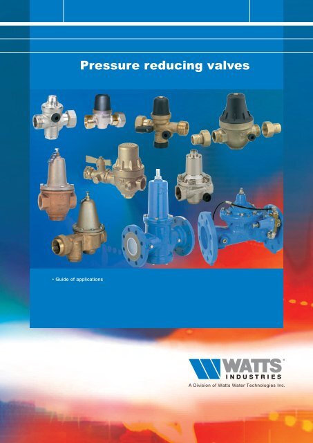
Pressure reducing valves - Watts Industries
Pressure reducing valves - Watts Industries
Pressure reducing valves - Watts Industries
Create successful ePaper yourself
Turn your PDF publications into a flip-book with our unique Google optimized e-Paper software.
• Guide of applications<br />
<strong>Pressure</strong> <strong>reducing</strong> <strong>valves</strong>
PRESSURE REDUCING vAlvES<br />
CONTENTS<br />
2<br />
page<br />
l The pressure <strong>reducing</strong> valve: Definition ___________________________________________________________________________________________________________________________3<br />
l Water savings _____________________________________________________________________________________________________________________________________________________________________________________________3<br />
l <strong>Pressure</strong> <strong>reducing</strong> <strong>valves</strong> or Regulators _______________________________________________________________________________________________________________________3<br />
l WATTS, the inventor of the regulator __________________________________________________________________________________________________________________________________4<br />
l How to choose the diameter of pressure <strong>reducing</strong> <strong>valves</strong> __________________________________________________________________________4<br />
l Installation ____________________________________________________________________________________________________________________________________________________________________________________________________5<br />
l How to adjust a pressure <strong>reducing</strong> valve ____________________________________________________________________________________________________________________5<br />
l Precautions __________________________________________________________________________________________________________________________________________________________________________________________________5<br />
l <strong>Pressure</strong> gauge: the essential accessory _______________________________________________________________________________________________________________________6<br />
l European standard EN 1567 and the brand NF___________________________________________________________________________________________________________6<br />
l Sanitary Conformity (ACS / WRAS) _________________________________________________________________________________________________________________________________________6<br />
l <strong>Pressure</strong> <strong>reducing</strong> valve, the WATTS INDUSTRIES expertise_______________________________________________________________________6<br />
l Case of electrical hot water storage heater_________________________________________________________________________________________________________________7<br />
l Case of tower blocks______________________________________________________________________________________________________________________________________________________________________7-8<br />
l Applications Guide ________________________________________________________________________________________________________________________________________________________________________________9<br />
l Product information sheets_________________________________________________________________________________________________________________________________________10 to 20
PRESSURE REDUCING vAlvES<br />
THE PRESSURE REDUCING vAlvE: DEFINITION<br />
This valve reduces the pressure of the water that goes through it, and is used to obtain a regulated and constant value<br />
at its outlet.<br />
3<br />
It is installed at the water mains (for a bungalow as for a flat). It protects the whole installation from problems due to excess<br />
pressure: noises in the pipes, water hammer, splashes, premature wear of household electrical appliances and taps.<br />
The pressure <strong>reducing</strong> <strong>valves</strong> are completely automatic.<br />
WATER SAvINGS<br />
Water represents a major part of household budgets.<br />
Not wasting it makes for real savings, but do you know that 30% of water used in a house is heated.<br />
Less pressure means less water used, and therefore less energy consumed.<br />
Through its low load losses, the WATTS INDUSTRIES pressure <strong>reducing</strong> <strong>valves</strong> allow the obtaining of a normal flow rate<br />
when water in drawn in several places simultaneously.<br />
The toilet flushing is less noisy and the taps no longer splash.<br />
Example with a tap running for 10 minutes.<br />
A considerable amount of the distributed water is directly dumped into the sewer without even having been truly used (see<br />
illustration above).<br />
Reducing the pressure, all in obtaining comfort in use, allows for real savings.<br />
In all cases, make a regular check of the condition of the tap and toilet flusher seals: a leak consumes a lot more water than<br />
you think ! (sometimes up to 3 m 3 per day for a private household).<br />
PRESSURE REDUCING vAlvES OR REGUlATORS <br />
We use the standardised official term « REDUCER », but a pressure <strong>reducing</strong> valve is highly sensitive to upstream pressure<br />
variations, and regulates badly without water flowing (without drawing).<br />
The WATTS INDUSTRIES direct action pressure <strong>reducing</strong> <strong>valves</strong> (PRECISIO, U5B, REGLEAU) regulate the downstream<br />
pressure as well with or without water flowing (without drawing). The downstream pressure only varies by 8% from the<br />
upstream pressure variation. These appliances are therefore PRESSURE REGULATORS.
PRESSURE REDUCING vAlvES<br />
WATTS, THE INvENTOR OF THE REGUlATOR<br />
4<br />
• In 1876: Invention, manufacturing and marketing of the first regulator.<br />
It was somewhat complicated, took up a lot of space (nearly 2 metres high), but it worked.<br />
• 1930: A half century had already gone by.<br />
Everything was designed – the principle of the direct action regulator valve with<br />
diaphragm operating the flap valve, the interior shape, the general look.<br />
• From this date, most regulators made in the world were inspired by or copied this format.<br />
The unique design of the WATTS pressure <strong>reducing</strong> valve makes it insensitive to scale or impurities, and needs no<br />
maintenance.<br />
The diaphragm, spring, seat and flap valve are largely dimensioned for precise and constant regulation all in allowing high<br />
flow rates.<br />
A corrosion-free spring (1) with a large spiral and highly sensitive:<br />
it guarantees precise adjustment. The pressure control is within the<br />
1,5 to 5,5 bar range.<br />
A high-temperature diaphragm (2) and a flap valve (3):<br />
resist high temperatures (up to 80°C).<br />
A stainless steel seat (4): an exclusivity that protects from wear<br />
and water aggressivity. Give a long-life guarantee.<br />
A single-unit body in non-dezincificable brass (5) (DZR):<br />
highly robust, this metal is resistant to corrosion and satisfies the<br />
new health standards on the compatibility of materials in contact<br />
with drinking water.<br />
A yoke and flap valve assembly (6): single-piece moving part in<br />
non-dezincificable brass (DZR), the yoke includes a flap valve (3)<br />
that is largely dimensioned, allowing higher performance<br />
to standard requirements.<br />
PRECISIO, U5B and REGLEAU use this direct action technique, with yoke and diaphragm.<br />
HOW TO CHOOSE THE DIAMETER OF PRESSURE REDUCING vAlvES <br />
Practical rule: the pressure <strong>reducing</strong> valve is generally chosen according to the diameter of the installed pipe, provided,<br />
of course, that the latter is of the right size.<br />
The choice of pipe diameters must follow the rules of the trade and must conform to the standards in force.<br />
Refer to the flow rate curves of each pressure <strong>reducing</strong> valve, given in the technical documents.
PRESSURE REDUCING vAlvES<br />
INSTAllATION<br />
WATTS pressure <strong>reducing</strong> <strong>valves</strong> may be installed in all positions.<br />
They are generally installed directly after the water meter, and thus<br />
protect the whole installation.<br />
5<br />
PRECISIO has 2 side connections and not a single one under<br />
the appliance unlike similar <strong>valves</strong> offered in the market.<br />
Advantage of a pressure gauge connection on the front: when 2 tubes are parallel with the wall, one above the other.<br />
The pressure gauge<br />
is easily screwed<br />
onto one of the<br />
two side connections.<br />
The tube underneath makes it<br />
impossible to mount the pressure<br />
gauge directly on most pressure<br />
<strong>reducing</strong> <strong>valves</strong> on the market.<br />
HOW TO ADJUST A PRESSURE REDUCING vAlvE <br />
THE ADJUSTMENT MUST BE DONE WITHOUT FLOW – NO DOWNSTREAM OUTFLOW.<br />
The WATTS INDUSTRIES pressure <strong>reducing</strong> <strong>valves</strong> are factory preset at 3 bar.<br />
They remain adjustable within a 1,5 to 5,5 bar range.<br />
• To increase the pressure, tighten the adjusting screw (clockwise as you look at the screw<br />
from above).<br />
• To reduce the pressure, undo the adjusting screw (anticlockwise as you look at the<br />
screw from above), slightly open a tap for a moment, close again, then tighten the screw<br />
again until you obtain the desired pressure.<br />
Two 1/4" gauge ports are located on each side of the valve when a pressure gauge<br />
is required to be fitted.<br />
When opening the downstream tap (drawing), it is<br />
normal to see the pressure drop: this is the load loss<br />
of the appliance.<br />
PRECAUTIONS<br />
This value is given in the appliance flow rate curves<br />
(see technical documents).<br />
WATTS INDUSTRIES direct action water pressure <strong>reducing</strong> <strong>valves</strong> are insensitive to scale or impurities, and need no<br />
maintenance or particular precautions provided that they are installed according to the rules of the trade.<br />
However, if there is a risk of back pressure or water hammer in the downstream circuit, you are advised to protect the<br />
pressure <strong>reducing</strong> valve by a non-return valve placed immediately downstream.<br />
Typical connection conforming to health and technical requirements:<br />
<strong>Pressure</strong> <strong>reducing</strong> valve NF<br />
PRECISIO<br />
multi-threaded M 3/4” - F 1/2”<br />
Anti-pollution<br />
non-return valve NF<br />
Water meter<br />
Faster and more practical, the multi-threaded models 86315 or 86216 are installed<br />
directly after the water meter and/or after the anti-pollution non-return valve.
PRESSURE REDUCING vAlvES<br />
PRESSURE GAUGE: THE ESSENTIAl ACCESSORY<br />
6<br />
The pressure gauge allows direct reading of the pressure, and thus allows precise<br />
adjustment of the pressure <strong>reducing</strong> valve to local installation conditions.<br />
WATTS INDUSTRIES designs, manufactures and markets a wide range of pressure<br />
gauges for buildings and industry.<br />
Over the years, through the successive acquisition of FIMET and the German company<br />
Förster & Rothmann, the WATTS INDUSTRIES group has become a key player in the<br />
European instrumentation market.<br />
The pressure gauge should not remain under pressure – the installation of an isolating<br />
valve is recommended.<br />
EUROPEAN STANDARD EN 1567 AND THE bRAND NF<br />
The brand NF guarantees the observance of standards for using household electrical appliances and taps.<br />
PRECISIO has the right to use the NF EN 1567 brand, and ensures user comfort and preservation of installations:<br />
by distributing a normal flow rate during simultaneous drawings, thanks to its low load loss.<br />
PRECISIO reduces the noise of running water. It facilitates the adjustment of mixers, by <strong>reducing</strong> the water hammer effect<br />
and avoiding rattling and vibrations in the pipes, characteristic phenomena of excessive pressure.<br />
PRECISIO helps towards saving water by avoiding waste (leakage from pipes, taps and toilet flushers).<br />
Through its design, it keeps its characteristics in time regardless of the water quality.<br />
SANITARY CONFORMITY (ACS / WRAS)<br />
These certificates assure the sanitary approvals - according to local requirements -<br />
A.C.S. (F) and WRAS (GB).<br />
PRESSURE REDUCING vAlvES, THE WATTS INDUSTRIES EXPERTISE<br />
WATTS, inventor of the modern pressure <strong>reducing</strong> valve concept, designs and manufactures<br />
a complete range for all needs.<br />
WATTS pressure <strong>reducing</strong> <strong>valves</strong> offer:<br />
- The best for you and your customers, because depending on quality products ensures peace of mind.<br />
- Easy installation: PRECISIO and REGLEAU are interchangeable with the main pressure <strong>reducing</strong><br />
<strong>valves</strong> on the market. They can be installed in all positions.<br />
- Savings: WATTS pressure <strong>reducing</strong> <strong>valves</strong> are sold at a competitive price.<br />
They ensure real water savings for your customers. They pay for themselves quickly.<br />
- Conformity to standards, the quality of the materials used, the NF brand,<br />
the health conformity attestation, etc. are all guarantees for your installations.<br />
- Reliability: manufacturing under quality assurance ISO 9001 (version 2008)<br />
in our plant at HAUTVILLERS OUVILLE (80 – Somme).<br />
- By experience acquired on the job, the success of REDUFIX is due to installers insisting on this product,<br />
with more than 20 years on the market.
PRESSURE REDUCING vAlvES<br />
CASE OF ElECTRICAl HOT WATER STORAGE HEATER:<br />
As the water temperature increases, the pressure also rises<br />
within the heater chamber (water expansion).<br />
For safety reasons, this pressure must be limited to a value<br />
under the safety pressure of the tank. This function is ensured<br />
by the safety group, which is set at 7 bar (standard NF-<br />
D 36401 - EN1487).<br />
An aggravating factor – the consumption of water during the<br />
night drops considerably, which has the consequence of increasing<br />
pressure in the public drinking water network.<br />
Now, it is generally during the night that the heating period<br />
is triggered (case of electric meters with off-peak time rates).<br />
Thus the heating of the water adds to the increase of water<br />
mains pressure, and causes the pressure in the hot water<br />
storage heater to reach the safety valve set-point,<br />
producing a water outflow higher than water expansion.<br />
To avoid this water outflow (drinking and heated),<br />
it is necessary to install a pressure <strong>reducing</strong> valve,<br />
that will protect the immersion tank from excess pressure.<br />
REDUFIX is an especially designed pressure <strong>reducing</strong> valve<br />
for this function.<br />
It is a good-looking design, very discreet and compact, perfect<br />
for built-in under counter electrical immersion<br />
heaters.<br />
Dielectric insulating connection<br />
Thermostatic<br />
Mixing <strong>valves</strong> MMV-C<br />
Mixed water<br />
Hot water<br />
Cold water inlet<br />
hot water<br />
storage heater<br />
Cold water inlet<br />
<strong>Pressure</strong> <strong>reducing</strong> valve<br />
REDUFIX<br />
Safety group<br />
SFR 3/4"<br />
Deflector<br />
Trap funnel kit<br />
Drainage<br />
7<br />
CASE OF TOWER blOCKS:<br />
Case No. 1: 6-storey building - « Normal » water mains pressure: 6 bar - Desired pressure in each flat: 3 bar.<br />
In the case of a residential building, it is advisable to install a pressure <strong>reducing</strong> valve at the input of each flat,<br />
and not a centralised pressure <strong>reducing</strong> valve at the bottom of the building.<br />
Why : we should consider a height of 3 metres for each storey, a load loss per storey of 0.3 bar.<br />
Therefore, if you install a single central pressure <strong>reducing</strong> valve at the bottom of the building adjusted to 3 bar,<br />
the first storeys will be supplied at the right pressure, but the more you go up the storeys, the more the pressure will drop.<br />
For example, the 6 th floor will have only 1.4 bar of available pressure, too low.<br />
It is therefore necessary to install the same pressure <strong>reducing</strong> valve, adjusted to 3 bar, at the entry of each flat.
PRESSURE REDUCING vAlvES<br />
Case No. 2: Building of more than 6-storeys - « High » water mains pressure: 10 bar -<br />
Desired pressure in each flat: 3 bar.<br />
8<br />
In the case of a residential building where the mains water pressure is very high, you are advised to install on the main<br />
inlet a pressure <strong>reducing</strong> valve of a larger diameter, which will firstly reduce the pressure to 6 bar, and a pressure<br />
<strong>reducing</strong> valve adjusted to 3 bar at the entry of each flat.<br />
The vertical columns are thus protested by the larger pressure <strong>reducing</strong> valve, and each level by a smaller pressure<br />
<strong>reducing</strong> valve to give a pressure of 3 bar.<br />
Remark: For very high buildings, the highest storeys do not require the installation of a pressure <strong>reducing</strong> valve when<br />
the pressure is less than 3 bar.<br />
Case No. 3: Building of more than 6-storeys - « Low » water mains pressure: 3 bar<br />
Desired pressure in each flat: 3 bar.<br />
In this case, the installation of a pressure booster is necessary.<br />
This will be adjusted to a value of 5 or 6 bar, the purpose being to obtain adequate pressure at all floors.<br />
It is therefore necessary to install the same pressure <strong>reducing</strong> valve, adjusted to 3 bar, at the entry of each flat.<br />
Remark: again, for very high buildings, the highest storeys do not require the installation of a pressure <strong>reducing</strong> valve<br />
when the pressure is less than 3 bar.
PRESSURE REDUCING vAlvES<br />
Guide of applications<br />
To choose the most suitable products, follow the applications below.<br />
APPLICATION<br />
MODEL<br />
<strong>Pressure</strong><br />
maxi (bar)<br />
<strong>Pressure</strong> setting<br />
range (bar)<br />
Diameters<br />
availables<br />
Pages<br />
9<br />
Protecting electric hot water<br />
storage heaters<br />
and household appliances<br />
➤<br />
➤<br />
REDUFIX<br />
REDUBAR<br />
15<br />
15<br />
1,5 to 5<br />
1,5 to 4<br />
1/2” to 3/4”<br />
1/2” to 3/4”<br />
10<br />
11<br />
➤<br />
REDUBLOC 15 1,5 to 4 3/4” 11<br />
Building and domestic<br />
installations<br />
➤<br />
REDUFIX<br />
15<br />
1,5 to 5<br />
1/2” to 3/4”<br />
10<br />
➤<br />
REDUBAR<br />
15<br />
1,5 to 4<br />
1/2” to 3/4”<br />
11<br />
➤<br />
➤<br />
REDUBLOC 15 1,5 to 4 3/4” 11<br />
REDUPRESS 16 1,5 to 5,5 1/2” to 3/4” 14<br />
➤<br />
PRECISIO<br />
25<br />
1,5 to 5,5<br />
1/2” to 3/4”<br />
12 - 13<br />
Collective installations<br />
➤<br />
➤<br />
REDUBLOC 15 1,5 to 4 3/4” 11<br />
REDUPRESS 16 1,5 to 5,5 1/2” to 3/4” 14<br />
➤<br />
PRECISIO<br />
25<br />
1,5 to 5,5<br />
1/2” to 3/4”<br />
12 - 13<br />
➤<br />
REGLEAU<br />
20<br />
1,5 to 5,5<br />
1” to 3”<br />
15<br />
➤<br />
DRVD<br />
16<br />
1,5 to 6<br />
DN 50<br />
to DN 200<br />
17<br />
➤<br />
PR500<br />
25<br />
1 to 7<br />
DN 50<br />
to DN 250<br />
18 - 19<br />
Industrial installations<br />
➤<br />
REDUBLOC<br />
15<br />
1,5 to 4<br />
3/4”<br />
11<br />
➤<br />
PRECISIO<br />
25<br />
1,5 to 5,5<br />
1/2” to 3/4”<br />
12 - 13<br />
➤<br />
REGLEAU<br />
20<br />
1,5 to 5,5<br />
1” to 3”<br />
15<br />
➤<br />
DRVD<br />
16<br />
1,5 to 6<br />
DN 50<br />
to DN 200<br />
17<br />
➤<br />
PR500<br />
25<br />
1 to 7<br />
DN 50<br />
to DN 250<br />
18 - 19
PRESSURE REDUCING vAlvES<br />
10<br />
<strong>Pressure</strong> <strong>reducing</strong> valve REDUFIX<br />
<strong>Pressure</strong> <strong>reducing</strong> valve with piston and diaphragm,<br />
is designed for protecting single appliance like hot water<br />
storage heaters and household appliances.<br />
It is directly fitted upstream of the appliance that you want<br />
to protect or to water circuit inlets that you want to protect<br />
(kitchen, bathrooms, garden piping etc.).<br />
ref. code: 82000 - F/F 1/2”<br />
± 0,31 kg<br />
Body and head in DZR brass, corrosion resistant.<br />
Finish: nickel plated.<br />
Diaphragm in NBR.<br />
Female 1/4” pressure gauge outlet.<br />
• Compact<br />
Takes up less space, easier to fit, and is unobtrusive<br />
underneath hot water storage heaters.<br />
• Any position<br />
The REDUFIX can be fitted in any position.<br />
• Robust<br />
ref. code 82210:<br />
special for safety group<br />
Once fitted you can forget it. The REDUFIX does not<br />
require any special maintenance.<br />
• Silent<br />
The valve system design and types of seals used ensure<br />
operation with no vibration and no rattling about.<br />
ref. code: 82210 and 82211<br />
M 3/4”/F free union nut 3/4”<br />
± 0,36 kg<br />
• Specific discharge<br />
Discharge is appropriate to isolated appliances like washing<br />
machines or hot water storage heaters. It performs a role in<br />
better thermostatic mixer control and controlled water<br />
consumption.<br />
• Practical<br />
Its Female 1/4” pressure gauge port is located on the front<br />
and not under the valve.<br />
Max. inlet pressure: 15 bar. Max. temperature: 70°C.<br />
Factory preset at 3 bar (± 0,5) adjustable from 1,5 to 5 bar.<br />
ref. code: 82110 - M/M 3/4”<br />
± 0,32 kg<br />
ref. code: 82215<br />
F 3/4” free union nut/M 3/4”<br />
± 0,36 kg<br />
<strong>Pressure</strong> drop diagram<br />
ref. code: 82007<br />
double threaded<br />
M3/4” F1/2” - M3/4” F1/2”<br />
± 0,32 kg<br />
Under the following conditions: 8 bar inlet, 3 bar outlet.<br />
diameter presentation ref. code<br />
F/F 1/2” (15x21) box 82000<br />
M/F 3/4” free union nut (20x27) box 82210<br />
M/F 3/4” free union nut (20x27) under hull 82211<br />
F 3/4” free union nut/M 3/4” (20x27) box 82215<br />
M/M 3/4” (20x27) box 82110<br />
M/M 3/4” and F/F 1/2” (double threaded) box 82007<br />
DN 15 compression fitting box 82114<br />
DN 22 compression fitting box 82115<br />
ref. code: 82114<br />
compression fitting 15 mm<br />
ref. code: 82115<br />
compression fitting 22 mm<br />
± 0,34 kg ± 0,38 kg
PRESSURE REDUCING vAlvES<br />
<strong>Pressure</strong> <strong>reducing</strong> valve REDUbAR<br />
ref. code 82500:<br />
special for safety group and<br />
electric hot water storage heater<br />
Compact pressure <strong>reducing</strong> valve.<br />
Redubar is an ideal pressure <strong>reducing</strong> valve for protecting<br />
electric hot water storage heaters, household appliances<br />
and vending machines.<br />
Internal mechanism in synthetic material to reduce<br />
the possibility of scaling.<br />
• Factory preset at 3 bar ± 0,5 (2,5 to 3,5 bar)<br />
can be set from 1,5 to 4 bar.<br />
• Maintenance free and robust device.<br />
• Brass body nickel plated and/or plain finished.<br />
• Slotted adjusting screw that can be turned with<br />
a flathead screwdriver.<br />
Max. temperature: 70°C.<br />
Max. inlet pressure: 15 bar.<br />
11<br />
Under the following conditions: 8 bar inlet<br />
3 bar outlet<br />
Male/Female free nut 3/4” (20x27).<br />
Multi-threaded Male 3/4” and Female 1/2” at inlet and outlet.<br />
Ref. 82500 Ref. 82501<br />
diameter ref. code packaging<br />
Male/Female free nut 3/4” (20x27) special for safety group 82500 40<br />
Multi-threaded Male 3/4” and Female 1/2” at inlet and outlet 82501 40<br />
REDUblOC 3.1<br />
Single device intended for water connection,<br />
combining 3 functions in one body.<br />
1. Isolating Valve<br />
2. <strong>Pressure</strong> <strong>reducing</strong> valve<br />
3. Approved controllable check valve<br />
• Easy mounting.<br />
• Respect for standards.<br />
• Competitive price.<br />
• Reduced weight and dimension.<br />
• 3 times less time to install.<br />
• Simple construction ensuring reliability and longevity.<br />
Max. temperature: 70°C.<br />
Max. inlet pressure: 15 bar.<br />
95 mm Maxi<br />
mm Maxi<br />
95<br />
water<br />
inlet<br />
direct monting by<br />
union free nut 3/4”<br />
<strong>Pressure</strong> <strong>reducing</strong> valve factory set at 3 bar.<br />
The setting is adjustable between 1,5 and 4 bar.<br />
Controllable check valve approved.<br />
downstream:<br />
double threading<br />
M 3/4”- F 1/2”<br />
Flow rate<br />
37.5 mm37.5 mm 49 mm 49 mm<br />
86.5 mm86.5 mm<br />
53.5 mm<br />
53.5 mm<br />
mm<br />
35<br />
mm<br />
35<br />
18.5 mm18.5 mm<br />
53.5 mm<br />
35 mm<br />
86.5 mm<br />
37.5 mm 49 mm<br />
18.5 mm<br />
water meter<br />
3/4”M (20x27)<br />
check valve<br />
checking plug<br />
Head loss<br />
diameter ref. code packaging<br />
F 3/4” free nut (20x27) x M 3/4” / F 1/2” 82900 25<br />
F 3/4” free nut (20x27) x M 3/4” / F 1/2” with checking pressure gauge 82901 25<br />
95
PRESSURE REDUCING vAlvES<br />
<strong>Pressure</strong> <strong>reducing</strong> valve PRECISIO M2<br />
12<br />
ref. 86300<br />
<strong>Pressure</strong> <strong>reducing</strong> valve with yoke and diaphragm.<br />
Reduce the water pressure without reduce the flow.<br />
Precisio M2 brings comfort by lowering the noise of water<br />
circulation and respecting acoustic norms.<br />
Reliable and without maintenance.<br />
Non-dezincificable (DZR) brass body.<br />
Diaphragm and a high temperature yoke assembly.<br />
Stainless steel seat.<br />
The adjustment is reliable and precise thanks to the screwand-nut<br />
system.<br />
Precisio is interchangeable with most market appliances.<br />
2 pressure gauge ports F 1/4” (8x13).<br />
Precisio M2 can be fitted in any position.<br />
Max. inlet pressure: 25 bar.<br />
Adjustable: 1,5 to 5 bar.<br />
Delivered preset at 3 bar.<br />
Max. temperature: 80°C.<br />
Standard NF approved EN 1567.<br />
PRECISIO multi-threaded (composite or brass cover)<br />
is issued with 2 reversible multi-threaded connectors with free nuts.<br />
External male<br />
DN 20x27 (3/4”)<br />
External male<br />
DN 20x27 (3/4”)<br />
ref. 86315<br />
or<br />
or<br />
Internal female<br />
DN 15x21 (1/2”)<br />
Internal female<br />
DN 15x21 (1/2”)<br />
Reversible<br />
Female 3/4”<br />
Male 1/2”<br />
Male 1/2”<br />
Female 3/4”<br />
ref. 86200<br />
DOWNSTREAM<br />
UPSTREAM<br />
Male<br />
DN 15 - 1/2”<br />
Male<br />
DN 20 - 3/4”<br />
Female<br />
DN 15 - 1/2”<br />
Female<br />
DN 20 - 3/4”<br />
ref. 86216<br />
Male<br />
DN 15<br />
1/2”<br />
Male<br />
DN 20<br />
3/4”<br />
Female<br />
DN 15<br />
1/2”<br />
Female<br />
DN 20<br />
3/4”<br />
± 0,864 kg ± 0,796 kg ± 0,796 kg<br />
± 0,864 kg<br />
154 mm<br />
approx.*<br />
± 0,796 kg<br />
127 mm<br />
approx.<br />
± 0,796 kg<br />
127 mm<br />
approx.<br />
143 mm<br />
approx.*<br />
127 mm<br />
approx.<br />
100 mm<br />
approx.<br />
100 mm<br />
approx.<br />
117 mm<br />
approx.*<br />
127 mm<br />
approx.<br />
± 0,729 kg ± 0,729 kg<br />
100 mm<br />
approx.<br />
± 0,729 kg ± 0,729 kg<br />
100 mm<br />
approx.<br />
117 mm<br />
approx.*<br />
143 mm<br />
approx.*<br />
± 0,796 kg<br />
117 mm<br />
approx.*<br />
± 0,796 kg<br />
117 mm<br />
approx.*<br />
± 0,864 kg ± 0,796 kg<br />
± 0,796 kg<br />
± 0,864 kg<br />
132 mm<br />
approx.*<br />
* measured in relation to the support surface of the piping nozzle on which the joint is going to apply.
PRESSURE REDUCING vAlvES<br />
Precisio M2<br />
multi-threaded<br />
3/4”-1/2”<br />
ref.: 86315<br />
issued with 2<br />
reversible<br />
connectors<br />
± 0,864 kg<br />
Precisio M2<br />
FF 3/4”<br />
ref.: 86300<br />
± 0,654 kg<br />
13<br />
Precisio<br />
multi-threaded<br />
3/4”-1/2”<br />
ref.: 86216<br />
issued with 2<br />
reversible<br />
connectors<br />
± 1,230 kg<br />
Precisio<br />
FF 3/4”<br />
ref.: 86200<br />
± 1,020 kg<br />
Precisio multi-threaded<br />
connected in F/F 1/2”<br />
Head loss (bar)<br />
Precisio F/F 3/4” and<br />
multi-threaded<br />
connected in M/M 3/4”<br />
Flow (L/min)<br />
ref. 86300 ref. 86216<br />
ref. 86200<br />
ref. 86315<br />
diameter type ref. code<br />
F/F 3/4” (20x27) Precisio M2 F/F 3/4” 86300<br />
Multi-threaded 3/4” - 1/2” + 2 reversible connectors Precisio M2 multi-threaded 86315<br />
F/F 3/4” (20x27) Precisio brass F/F 3/4” 86200<br />
Multi-threaded 3/4” - 1/2” + 2 reversible connectors Precisio brass multi-threaded 86216
PRESSURE REDUCING vAlvES<br />
14<br />
<strong>Pressure</strong> <strong>reducing</strong> valve REDUPRESS<br />
<strong>Pressure</strong> <strong>reducing</strong> valve with piston and diaphragm.<br />
Ideal pressure <strong>reducing</strong> valve for domestic, commercial and<br />
industrial installations:<br />
Individual water supply for low-cost building sites (flat,<br />
bungalow, etc.).<br />
Max. inlet pressure: 16 bar.<br />
Two 1/4" (8x13) side connections for pressure gauge.<br />
Body: corrosion resistant DZR brass, nickel finished.<br />
Diaphragm in EPDM.<br />
Adjustment of setting by screw on the top of the cover.<br />
Max. temperature: 80°C.<br />
Adjustable: 1,5 to 5,5 bar.<br />
SPECIAL LOW PRESSURE MODEL*:<br />
Adjustable: 0,5 to 2,5 bar.<br />
Max. inlet pressure: 8 bar.<br />
Flow: 25 L/min. under 0,5 bar.<br />
F/F 3/4”<br />
<strong>Pressure</strong> drop diagram for standard REDUPRESS 1,5 to 5,5 bar<br />
F/F 1/2”<br />
M/M 3/4”<br />
diameter type of pressure ref. code<br />
F/F 1/2” standard pressure 81100<br />
* F/F 1/2” low pressure 81106<br />
F/F 3/4” standard pressure 81116<br />
* F/F 3/4” low pressure 81113<br />
M/M 3/4” standard pressure 81015<br />
F/F 1/2” with pressure gauge standard pressure 81101<br />
F/F 3/4” with pressure gauge standard pressure 81117<br />
M/M 3/4” with pressure gauge standard pressure 81016<br />
<strong>Pressure</strong> gauge 0 to 10 bar 66206
PRESSURE REDUCING vAlvES<br />
<strong>Pressure</strong> <strong>reducing</strong> valve REGlEAU G.C.<br />
<strong>Pressure</strong> <strong>reducing</strong> valve with disc-yoke and diaphragm.<br />
• Yoke and diaphragm assembly: cast solid moving part highly<br />
sensitive spring and large diaphragm permits accurate<br />
adjustment and excellent performances.<br />
• Stainless spring with large coils and high sensitivity:<br />
it guarantees a precise adjustment.<br />
• Diaphragm and valve high temperature: resisting high<br />
temperatures (up to 70°C).<br />
Max. temperature: 70°C.<br />
Max. inlet pressure:<br />
until 20 bar.<br />
Adjustable: 1,5 to 5,5 bar.<br />
Delivered preset at 3 bar.<br />
Flow: until 40 m 3 /h.<br />
Assembly any position.<br />
15<br />
• Stainless steel seat: an exclusive design which protects the<br />
valve from the aggressive wear of water.<br />
A guarantee of longevity.<br />
For hot or cold water.<br />
Seat: stainless steel.<br />
Body: bronze.<br />
Models 1” and 1”1/4<br />
Models 2”1/2 and 3”<br />
Head loss (bar)<br />
Head loss (bar)<br />
Models 1”1/2 and 2”<br />
Flow rate (litres/mn)<br />
Head loss (bar)<br />
Flow rate (litres/mn)<br />
Flow rate (litres/mn)<br />
diameter A (mm) B (mm) C (mm) type ref. code<br />
F/F 1” (26x34) 121 54 165 Regleau G.C. 28602<br />
F/F 1”1/4 (33x42) 127 70 172 Regleau G.C. 28603<br />
F/F 1”1/2 (40x49) 171 70 251 Regleau G.C. 28604<br />
F/F 2” (50x60) 203 86 273 Regleau G.C. 28605<br />
F/F 2”1/2 By-pass (66x76) 200 73 273 Regleau G.C. 28616<br />
F/F 3” By-pass (80x90) 267 105 324 Regleau G.C. 28617
PRESSURE REDUCING vAlvES<br />
<strong>Pressure</strong> <strong>reducing</strong> valve with by-pass U5b<br />
16<br />
<strong>Pressure</strong> <strong>reducing</strong> valve with yoke and diaphragm,<br />
with built-in filter and by-pass.<br />
• Inlet swivel union nuts.<br />
• Built in filter easily removable, upstream of the device.<br />
• Large spring and diaphragm for a precise adjustment.<br />
• Maintainability without special tools.<br />
• Horizontal or vertical assembly, fluid going up.<br />
Diaphragm: Nordel with nylon.<br />
Valve: Buna.<br />
Body bronze, seat and spring stainless steel.<br />
Max. inlet pressure:<br />
until 20 bar.<br />
Adjustable: 1,5 to 5,5 bar.<br />
Delivered preset at 3 bar.<br />
Max. temperature: 80°C.<br />
Connection for pressure<br />
gauge on request<br />
U5B with 1/4” female pressure<br />
U5B standard: without gauge port underneath valve<br />
pressure gauge port (supplied with plug)<br />
diameter A (mm) B (mm) C (mm) weight (kg) ref. code U5B Standard ref. code U5B pressure gauge<br />
F/F 1/2” (15x21) 108 47 146 1,8 28100 28107<br />
F/F 3/4” (20x27) 114 50 162 2,3 28101 28108<br />
F/F 1” (26x34) 152 50 175 2,7 28102 28109<br />
F/F 1”1/4 (33x42) 180 60 200 4,2 28103 28110<br />
F/F 1”1/2 (40x49) 200 80 240 6,5 28104 28111<br />
F/F 2” (50x60) 240 85 279 10,4 28105 28112<br />
special pressure gauge for U5B - reversed reading 0/10 bar 66106<br />
HYDROblOC<br />
HYDROBLOC is a cold water or hot water supply unit<br />
incorporating 5 functions:<br />
- Direct assembly below meter by free nut.<br />
- Isolating valve built into spherical brass valve.<br />
- Testable antipollution check valve approved by WRAS,<br />
KIWA, DVGW, NF, SVGW.<br />
- Drain device for bleeding the downstream installation.<br />
- <strong>Pressure</strong> <strong>reducing</strong> valve with yoke and diaphragm<br />
with 2 pressure taps either side of the device.<br />
Max. inlet pressure: 16 bar.<br />
Adjustable: 1,5 to 5,5 bar.<br />
Composition:<br />
description<br />
Meter connection by 3/4” free nut<br />
Spherical 1/4 turn valve<br />
Check valve test orifice<br />
Antipollution check valve<br />
Drain system (hexagon brass cap)<br />
<strong>Pressure</strong> adjusting screw (1,5 to 5,5 bar approx.)<br />
<strong>Pressure</strong> <strong>reducing</strong> valve<br />
Connection for pressure gauge<br />
F3/4” connection<br />
Ideal to save time and space = 5 functions, 1 only assembly!<br />
Two 1/4" (8x13) side ports for pressure gauge.<br />
Rough brass finished.<br />
Dimensions:<br />
diameter<br />
ref. code<br />
HYDROBLOC - Female 3/4” free nut / female 3/4” 84050
PRESSURE REDUCING vAlvES<br />
<strong>Pressure</strong> <strong>reducing</strong> valve with flanges DRvD PN16<br />
Model with balanced valve and piston, guidance sleeve valve<br />
machined and polished. EPDM reinforced seals.<br />
Body ductile cast iron covered epoxy varnish.<br />
Standard assembly in horizontal position (setting screw to<br />
the top).<br />
Ring cast iron. For cold water maxi. 40°C.<br />
Plugs F 1/4” for pressure gauge on two sides of the body,<br />
Standard: PN16 setting from 1,5 to 6 bar.<br />
PN25 setting from 4 to 12 bar.<br />
Max. inlet pressure: 16 bar.<br />
Max. temperature: 40°C.<br />
Kits of seals or springs availables.<br />
On request: setting kit 2 to 8<br />
bar or 4 to 12 bar (specify the<br />
DRVD diameter).<br />
17<br />
diameter setting range type ref. code packaging<br />
DN 50 1,5 to 6 bar DRVD PN16 L 05.04.053 1<br />
DN 65 1,5 to 6 bar DRVD PN16 L 05.04.068 1<br />
DN 80 1,5 to 6 bar DRVD PN16 L 05.04.083 1<br />
DN 100 1,5 to 6 bar DRVD PN16 L 05.04.103 1<br />
DN 125 1,5 to 6 bar DRVD PN16 L 05.04.128 1<br />
DN 150 1,5 to 6 bar DRVD PN16 L 05.04.153 1<br />
DN 200 (on request) 1,5 to 6 bar DRVD PN16 L 05.04.203 1<br />
<strong>Pressure</strong> <strong>reducing</strong> valve with flanges DRvD PN25<br />
Identical model to the standard DRVD above but PN25 and setting from 4 to 12 bar.<br />
Consult us for the time.<br />
diameter setting range type ref. code packaging<br />
DN 50 4 to 12 bar DRVD PN25 L 05.04.050 1<br />
DN 65 4 to 12 bar DRVD PN25 L 05.04.065 1<br />
DN 80 4 to 12 bar DRVD PN25 L 05.04.080 1<br />
DN 100 4 to 12 bar DRVD PN25 L 05.04.100 1<br />
DN 125 4 to 12 bar DRVD PN25 L 05.04.125 1<br />
DN 150 4 to 12 bar DRVD PN25 L 05.04.150 1<br />
Spring kits (2 to 8 bar)<br />
ref. code<br />
type<br />
L 05.99.070 DF 8/DRVD 50<br />
L 05.99.071 DF 8/DRVD 65<br />
L 05.99.072 DF 8/DRVD 80<br />
L 05.99.073 DF 8/DRVD 100<br />
L 05.99.075 DF 8/DRVD 150<br />
Seals kits (PN 16 & PN 25)<br />
diameter type ref. code<br />
DN 50 JT/DRVD L 05.99.200<br />
DN 65 JT/DRVD L 05.99.201<br />
DN 80 JT/DRVD L 05.99.202<br />
DN 100 JT/DRVD L 05.99.203<br />
DN 125 JT/DRVD L 05.99.204<br />
DN 150 JT/DRVD L 05.99.205<br />
DN 200 JT/DRVD L 05.99.206<br />
Seals bag for DRVD.<br />
Spring kits (4 to 12 bar)<br />
ref. code<br />
type<br />
L 05.99.080 DF 12/DRVD 50<br />
L 05.99.081 DF 12/DRVD 65<br />
L 05.99.082 DF 12/DRVD 80<br />
L 05.99.083 DF 12/DRVD 100<br />
L 05.99.084 DF 12/DRVD 125<br />
L 05.99.085 DF 12/DRVD 150<br />
L 05.99.086 DF 12/DRVD 200<br />
models DN L (mm) H (mm) h (mm) F (mm)<br />
DRV-D50 50 230 300 83 165<br />
DRV-D65 65 290 350 90 185<br />
DRV-D80 80 310 390 100 200<br />
DRV-D100 100 350 440 121 220<br />
DRV-D125 125 400 560 152 250<br />
DRV-D150 150 450 670 169 285<br />
DRV-D200 200 550 1050 234 340<br />
<strong>Pressure</strong> <strong>reducing</strong> valve DRVD - DN 50 and 65 <strong>Pressure</strong> <strong>reducing</strong> valve DRVD - DN 80 and 100 <strong>Pressure</strong> <strong>reducing</strong> valve DRVD - DN 125, 150 and 200
PRESSURE REDUCING vAlvES<br />
18<br />
<strong>Pressure</strong> <strong>reducing</strong> valve<br />
WATTS PR500<br />
For all the drinkable water supply networks: building,<br />
distribution of water, industry, pumping.<br />
Stabilizes automatically the pressure downstream with the<br />
regulated value.<br />
Very simple pressure adjustment by system screw and nut.<br />
Body cast iron covered epoxy integral interior, outside<br />
Seat: stainless.<br />
Standard assembly in horizontal position.<br />
(Vertical assembly fluid going up: DN 50 to DN 150 only).<br />
Max. pressure: 25 bar<br />
Max. temperature: 20°C<br />
Adjustable: 1 to 7 bar,<br />
(see cavitation curves).<br />
Simple construction.<br />
Minimum maintenance.<br />
Face<br />
upstream pressure<br />
gauge plug 3/8”<br />
models DN PN A (mm) B1 (mm) B2 (mm) C1 (mm) C2 (mm) weight (kg) pressure gauge plug<br />
PR500-50 50 16 230 170 85 165 95 25 F 3/8”<br />
PR500-65 65 16 290 170 85 165 95 25 F 3/8”<br />
PR500-80 80 16 310 175 85 165 100 30 F 3/8”<br />
PR500-100 100 16 350 190 120 210 110 40 F 1/2”<br />
PR500-125 125 16 400 200 150 285 125 70 F 1/2”<br />
PR500-150 150 16 480 210 150 285 145 90 F 1/2”<br />
PR500-200 200 16 600 235 200 360 170 150 F 1/2”<br />
PR500-250 250 16 730 280 255 475 200 400 F 1/2”<br />
Top<br />
downstream pressure<br />
gauge plug 3/8”<br />
1 - Body / Main valve<br />
2 - Fixed orifice<br />
3 - Flow strainer<br />
4 - Pilot valve<br />
5 - Air vent<br />
6 - Flexible tubing<br />
diameter range type ref. code.<br />
DN 50 1 to 7 bar PR500 PN16 500 050 548<br />
DN 65 1 to 7 bar PR500 PN16 500 065 548<br />
DN 80 1 to 7 bar PR500 PN16 500 080 548<br />
DN 100 1 to 7 bar PR500 PN16 500 100 548<br />
DN 125 1 to 7 bar PR500 PN16 500 125 548<br />
DN 150 1 to 7 bar PR500 PN16 500 150 548<br />
DN 200 1 to 7 bar PR500 PN16 505 200 548<br />
DN 250 1 to 7 bar PR500 PN16 505 250 548
PRESSURE REDUCING vAlvES<br />
Hydraulic characteristics:<br />
Cavitation: If the differential of pressure between the<br />
upstream and the desired downstream is too large, then<br />
it will be necessary to reduce the pressure in several<br />
stages by the installation of a series of pressure <strong>reducing</strong><br />
<strong>valves</strong>.<br />
A high inlet pressure and a low downstream pressure<br />
can cause a deterioration of the valve by cavitation.<br />
To avoid this phenomenon, please refer to the curves<br />
hereafter.<br />
19<br />
Repair kits:<br />
Cavitation<br />
(unautorized)<br />
Possibility of cavitation<br />
(not recommended)<br />
No cavitation<br />
(recommended)<br />
Example:<br />
15 bar upstream, 1 bar downstream = cavitation, unauthorized<br />
10 bar upstream, 4 bar downstream = no cavitation, authorized<br />
designation DN marks (draw) part no.<br />
SET 1 - disc and diaphragm assembly (internal NBR parts), including: axis, diaphragm, diaphragm disc, axis nut, brace<br />
washer, disc guide, seals and seat disc, disk support<br />
Internal set 2” (EU100 DN050/065/080) 50 / 65 / 80 4, 5, 8, 9, 10, 11, 12, 14, 15 500050920<br />
Internal set 3” (EU100 DN100)" 100 4, 5, 8, 9, 10, 11, 12, 14, 15 500080920<br />
Internal set 4” (EU100 DN125/150) 125 / 150 4, 5, 8, 9, 10, 11, 12, 14, 15 500100920<br />
Internal set 6” (EU100 DN200) 200 4, 5, 8, 9, 10, 11, 12, 14, 15 500150920<br />
Internal set 8” (EU100 DN250) 250 4, 5, 8, 9, 10, 11, 12, 14, 15 500200920<br />
SET 2 - valve base set (internal NBR parts), including: diaphragm, brace washer, seals and seat disc<br />
Internal set 2” (EU100 DN050/065/080) 50 / 65 / 80 5, 10, 11, 14 500050900<br />
Internal set 3” (EU100 DN100) 100 5, 10, 11, 14 500080900<br />
Internal set 4” (EU100 DN125/150) 125 / 150 5, 10, 11, 14 500100900<br />
Internal set 6” (EU100 DN200) 200 5, 10, 11, 14 500150900<br />
Internal set 8” (EU100 DN250) 250 5, 10, 11, 14 500200900<br />
SET 3 - seat set (stainless steel), including: stainless steel seat<br />
Seat set 2” (EU100 DN050/065/080) 50 / 65 / 80 13 500050910<br />
Seat set 3” (EU100 DN100) 100 13 500080910<br />
Seat set 4” (EU100 DN125/150) 125 / 150 13 on request<br />
Seat set 6” (EU100 DN200) 200 13 on request<br />
Seat set 8” (EU100 DN250) 250 13 on request<br />
Pilot 263AP brass body/aluminium cover 50 to 250 500/4 44001<br />
Other replacement parts<br />
Fixing ring 10 mm plastic 50 to 250 500/2 500000047<br />
Calibration strainer 10 mm stainless steel 50 / 65 / 80 500/3 544010122<br />
Calibration strainer 15 mm stainless steel 100 / 125 / 150 / 200 / 250 500/3 544015122<br />
Air vent 3/8” nickel plated brass 50 / 65 / 80 500/5 900257110<br />
Air vent 1/2” nickel plated brass 100 / 125 / 150 / 200 / 250 500/5 on request<br />
Flexible tubing 10 mm plastic PA 50 to 250 500/6 503000900<br />
Flexible tubing set with fittings 50 500/6 (with fittings) 503050946<br />
Flexible tubing set with fittings 65 500/6 (with fittings) 503065946<br />
Flexible tubing set with fittings 80 500/6 (with fittings) 503080946<br />
Flexible tubing set with fittings 100 500/6 (with fittings) 503100946<br />
Flexible tubing set with fittings 125 500/6 (with fittings) 503125946<br />
Flexible tubing set with fittings 150 500/6 (with fittings) 503150946<br />
Flexible tubing set with fittings 200 500/6 (with fittings) 503200946<br />
Flexible tubing set with fittings 250 500/6 (with fittings) 503250946
Product range <strong>Watts</strong> <strong>Industries</strong><br />
- System disconnectors<br />
- Backflow protection devices<br />
- Check <strong>valves</strong><br />
- Safety units<br />
- Safety relief <strong>valves</strong><br />
- <strong>Pressure</strong> <strong>reducing</strong> <strong>valves</strong><br />
- Automatic control <strong>valves</strong><br />
- Butterfly <strong>valves</strong><br />
- Shut off <strong>valves</strong><br />
- Measuring gauges<br />
- Temperature control<br />
- Expansion vessels<br />
- Process switches<br />
- Fuel products<br />
- Gas products<br />
- Electronic controls<br />
- Installation protection products<br />
- Radiator <strong>valves</strong><br />
- System products<br />
- Manifolds and fittings<br />
Re-order no. 55-UK-2012/11<br />
WATTS INDUSTRIES France<br />
1590 avenue d'Orange CS 10101 SORGUES 84275 VEDENE cedex - FRANCE<br />
Phone +33 (0)4 90 33 28 28 - Fax +33 (0)4 90 33 28 29/39<br />
www.wattsindustries.com - E-mail : info@wattsindustries.fr


