Seismic Analysis of Water Supply Systems by Earthquake Scenario ...
Seismic Analysis of Water Supply Systems by Earthquake Scenario ...
Seismic Analysis of Water Supply Systems by Earthquake Scenario ...

Create successful ePaper yourself
Turn your PDF publications into a flip-book with our unique Google optimized e-Paper software.
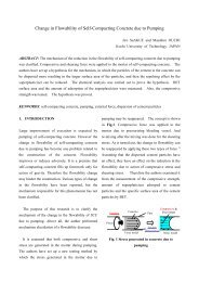
the post-earthquake performance <strong>of</strong> water systems<br />
has been developed at NCREE (Liu et al., 2010 &<br />
2011). It consists <strong>of</strong> several steps, as depicted in<br />
Figure 1. (1) estimate the seismic hazards (ground<br />
shaking and failure) <strong>of</strong> where the interested water<br />
network system locates, (2) simulate the locations <strong>of</strong><br />
pipe damages according to the hazards and pipe<br />
repair rates (numbers <strong>of</strong> repairs per unit pipe length<br />
caused <strong>by</strong> ground shaking and deformation,<br />
respectively), (3) classify the properties <strong>of</strong> each pipe<br />
damage (whether a break or a leak, and what which<br />
model <strong>of</strong> pipe leak if it is a leak; the probability<br />
model for pipe damages employed <strong>by</strong> GIRAFFE was<br />
adopted here), (4) modify the hydraulic model <strong>of</strong> the<br />
water network system to take into account the pipe<br />
damages, (5) execute EPANET and take out the<br />
water supply nodes affected <strong>by</strong> negative pressure<br />
from the solution. Details <strong>of</strong> these steps will be<br />
explained in the following sections.<br />
EQ source parameters<br />
ground motion attenuation<br />
site effect<br />
fault rupturing model<br />
liquefaction susceptibility<br />
liquefaction settlement model<br />
pipe repair rate<br />
pipe damage locating algorithm<br />
equipment vulnerability<br />
power outage<br />
…<br />
pipe damage hydraulic models<br />
EPANET s<strong>of</strong>tware<br />
pre- and post-processors<br />
EQ Event<br />
<strong>Seismic</strong> Hazards<br />
Ground<br />
Ground<br />
Shaking<br />
Failure<br />
Numbers <strong>of</strong><br />
Damage<br />
Pipe Damage<br />
and<br />
Malfunction<br />
Locations <strong>of</strong><br />
<strong>of</strong><br />
Pipe Damage<br />
Equipment<br />
Hydraulic <strong>Analysis</strong><br />
System Serviceability<br />
Figure 1 Flowchart for the serviceability assessment<br />
<strong>of</strong> water systems following earthquakes<br />
2. PIPE DAMAGE MODELING<br />
Repair rate (RR) is defined as the number <strong>of</strong> repairs<br />
(or damages) per unit pipe length (km). It is widely<br />
employed to indicate pipe fragility under seismic<br />
effects. Numerous investigations have been made to<br />
express the relationship between pipe repair rate and<br />
earthquake-induced ground shaking (e.g. peak<br />
ground acceleration, PGA) or ground failure (e.g.<br />
permanent ground displacement, PGD). The pipe<br />
material and diameter affect its repair rate, too. The<br />
empirical formulae for pipe repair rates have been<br />
proposed <strong>by</strong> the authors, which read (Liu et al.,<br />
2011):<br />
RR = C ⋅ RR 0<br />
RR<br />
0<br />
where<br />
RR PGA<br />
RR PGD<br />
= max[ RR ,RR ] + RR<br />
PGA<br />
=<br />
= 0.6445 ⋅ PGD<br />
PGDFault<br />
−3<br />
6.5756 × 10 ⋅ ( PGA −<br />
0.728<br />
PGDLiq<br />
100)<br />
0.878<br />
⋅ p<br />
where RR<br />
0<br />
is the standard pipe repair rate, C is<br />
an adjustment coefficient and is a function <strong>of</strong> pipe<br />
material and diameter, PGA and PGD are in<br />
cm/sec 2 and cm, respectively. The terms<br />
PGDFault<br />
,<br />
PGD<br />
Liq<br />
and p<br />
Liq<br />
represent the fault<br />
rupturing and soil liquefaction-induced PGDs, and<br />
the probability <strong>of</strong> occurrence <strong>of</strong> soil liquefaction,<br />
respectively.<br />
Conventionally, a stationary Poisson process is<br />
widely used to simulate the damage locations along a<br />
pipe. In this study, an approach based on the<br />
expected number <strong>of</strong> damages <strong>of</strong> pipes was otherwise<br />
proposed. From Figure 2, let the length <strong>of</strong> a typical<br />
pipe segment be L . Assume there are a total <strong>of</strong> N<br />
pipes in the water pipe network under study. Let all<br />
pipes be broken down into segments <strong>of</strong> constant<br />
length L from their beginning nodes (the length <strong>of</strong><br />
the last segment <strong>of</strong> each pipe may not equal L ), and<br />
be denoted as ( i , j)<br />
, where i refers to pipe i<br />
( i = 1,..., N ) and j refers to its j -th segment. The<br />
expected number <strong>of</strong> pipe damage <strong>of</strong> any pipe<br />
segment ( i , j)<br />
can be decided according to the<br />
segment length and the corresponding pipe repair<br />
Liq