environment impact evaluation of a new type continuous mixing
environment impact evaluation of a new type continuous mixing
environment impact evaluation of a new type continuous mixing

You also want an ePaper? Increase the reach of your titles
YUMPU automatically turns print PDFs into web optimized ePapers that Google loves.
ENVIRONMENT IMPACT EVALUATION OF A NEW TYPE CONTINUOUSMIXING PLANT FOR DAM CONSTRUCTIONTakayuki OBARA, Xuehui AN, Feng JINTsinghua UniversityABSTRACT: On concrete dam construction work, it is necessary to manufacture a large amount <strong>of</strong> concreteand CSG (Cemented Sand and Gravel). The manufacture plant <strong>of</strong> concrete and CSG is operated in very longterm, therefore the effect <strong>of</strong> its <strong>environment</strong>al <strong>impact</strong> could be serious. In general, there are two <strong>type</strong>s <strong>of</strong>manufacture plant on the process <strong>of</strong> manufacturing concrete or CSG. The one is batch <strong>type</strong> plant; its <strong>mixing</strong>process is not <strong>continuous</strong> and it is necessary to repeat the processes <strong>of</strong> measuring and <strong>mixing</strong> every batch.The other is <strong>continuous</strong> <strong>mixing</strong> plant; <strong>mixing</strong> process is completely <strong>continuous</strong>, at the same time, themeasurement and supplement <strong>of</strong> materials are also carried out <strong>continuous</strong>ly. Since <strong>continuous</strong> <strong>mixing</strong> plantcan manufacture a large amount <strong>of</strong> products at short time, <strong>continuous</strong> <strong>mixing</strong> plant is suitable formanufacture plant <strong>of</strong> concrete dam construction. But it is hard to control the quality <strong>of</strong> products, so batch<strong>type</strong> plant used to be adopted as the mixer <strong>of</strong> the manufacture plant. In recent years, the <strong>new</strong> <strong>continuous</strong><strong>mixing</strong> plant which can control the quality <strong>of</strong> products accurately has developed and been put to practical useon several projects <strong>of</strong> concrete and CSG dam construction. The best feature <strong>of</strong> this plant is its energy savingeffect. This plant is equipped with a static <strong>continuous</strong> mixer for <strong>mixing</strong> concrete or CSG. This mixer is set upin vertical direction, and then it is possible to mix materials with no electric power but only by gravity force.In this study, <strong>environment</strong>al <strong>impact</strong> due to manufacture concrete and CSG by conventional batch <strong>type</strong> plantand <strong>new</strong> <strong>continuous</strong> <strong>mixing</strong> plant are estimated and compared, and then the advantage <strong>of</strong> <strong>new</strong> continues<strong>mixing</strong> plant for <strong>environment</strong> is discussed.KEYWORDS: <strong>environment</strong>al <strong>impact</strong>, energy saving, <strong>continuous</strong> <strong>mixing</strong> plant1. INTRODUCTIONIn present-day life, various kinds <strong>of</strong> industrialproducts are produced all over the world, and itcauses to consume a large amount <strong>of</strong> naturalresources and energy, and causes to dischargeexhaust gas and industrial waste. Environmentalassessment is very important in every field <strong>of</strong>industry, and many research and investigating workshave been carried out. Life cycle assessment is amethod <strong>of</strong> evaluating the <strong>environment</strong>al <strong>impact</strong>systematically and quantitatively in the entire lifecycle <strong>of</strong> product and processes or activities. In thefield <strong>of</strong> construction, this method <strong>of</strong> life cycleassessment is also applied to a system <strong>of</strong><strong>environment</strong>al assessment, and is carried out actively.In project <strong>of</strong> dam construction, because damconstruction project is very big in scale, the project<strong>of</strong> dam construction has great influences on waterquality and natural <strong>environment</strong> <strong>of</strong> neighboring area.On the concrete dam construction project, themanufacture plant <strong>of</strong> concrete and CSG is operatedin very long term, and its <strong>environment</strong>al <strong>impact</strong>could be serious. From this point <strong>of</strong> view,<strong>environment</strong>al <strong>impact</strong>s due to operating manufactureplant <strong>of</strong> concrete and CSG on dam construction workis discussed in this research. And this research
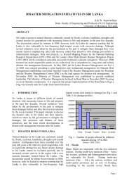
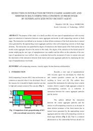
<strong>mixing</strong> plants were hard to control the quality <strong>of</strong>products, so batch <strong>type</strong> plant used to be adopted asthe manufacture plant for concrete dam construction.In recent years, the <strong>new</strong> <strong>continuous</strong> <strong>mixing</strong> plantwhich can control the quality <strong>of</strong> products accuratelyhas developed by Maeda et al. in Japan, and was putto practical use on several projects <strong>of</strong> concrete andCSG dam construction in Japan and China.Therefore our choice <strong>of</strong> manufacture plant becamewider. Fig.2 shows the outline <strong>of</strong> <strong>new</strong> <strong>continuous</strong><strong>mixing</strong> plant, this <strong>new</strong> <strong>continuous</strong> <strong>mixing</strong> plant ismainly composed <strong>of</strong> material feeders, belt conveyers,<strong>continuous</strong> mortal mixer and <strong>continuous</strong> concretemixer. In this system, the supply condition <strong>of</strong> eachconstituents <strong>of</strong> concrete is shown Fig.2 and managedby real time monitoring system in real time when<strong>mixing</strong>. And a <strong>continuous</strong> static mixer, witch iscalled “MY-mixer”, is adopted as concrete mixer.MY-mixer was developed by Maeda et al. Thestructure and <strong>mixing</strong> concept <strong>of</strong> MY-mixer is shownin Fig.3, it is composed <strong>of</strong> box shape units whichhave two vertically paralleled inlets and twohorizontally paralleled outlets, and the units areconnected in series. When materials get throughevery MY-mixer unit, materials are kneaded andlapped, as a result, two layers <strong>of</strong> materials at inletincrease by double <strong>of</strong> that to four layers (2 2 =4). If nnumber <strong>of</strong> MY-mixer units is connected, the number<strong>of</strong> material layers after getting through MY-mixer isequal to 2 n , this principle is called 2 n <strong>mixing</strong> theory<strong>of</strong> MY-mixer. In case <strong>of</strong> <strong>mixing</strong> concrete or CSG, theMY-mixer is set up in vertical direction as Fig.2, andthen it is possible to mix concrete without electricpower but only by gravity force. Tek Raj Gyawali etal. conducted comparisons <strong>of</strong> this <strong>new</strong> <strong>continuous</strong><strong>mixing</strong> plant and ordinary batch <strong>mixing</strong> plant forproductivity and quality <strong>of</strong> concrete, and theyconcluded that this system has capacity <strong>of</strong> producinglarge quantity <strong>of</strong> concrete with its precise quality,and this system not only rationalizes the concreteproduction work, but also helps to protect the<strong>environment</strong>al condition by decreasing electricconsumption in large scale.3. ENVIRONMENTAL INPACT DUE TOMANU- FACTURING CONCRETE AND CSGIn this research, the <strong>environment</strong>al <strong>impact</strong>s dueto manufacture concrete and CSG <strong>of</strong> damconstruction in case <strong>of</strong> operating batch <strong>mixing</strong> plantMortar mixer and feederWater+Add.SementFine AggregateCourse AggregateSmaller SizeMedium SizeLager SizeCourse AggregatefeederContinuesMortar MixerMonitoring!Monitoring!BeltConveyerCourseAggregateMixed MortarBeltConveyerContinuously!(connecting (connecting each each devices) devices)Monitoring!Fig.2 Outline <strong>of</strong> <strong>new</strong> <strong>continuous</strong> <strong>mixing</strong> plant.Mixed Mortar +Course AggregateContinuesConcreteMixerMY-mixerTo Site!
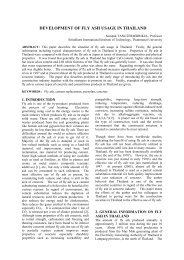
Inlet 2(2 1 )layersOutlet Inlet 4(2 2 )layersOutlet Inlet 8(2 3 )Outlet layersnn unitsMY-mixer2 nlayersVerticalInletHorizontaloutletFlow<strong>of</strong> MaterialsKneadingProcessLappingProcessFig.3 Continuous concrete mixer “MY-mixer” and its <strong>mixing</strong> theory.and <strong>continuous</strong> <strong>mixing</strong> plant are estimated anddiscussed. In these estimations, electricityconsumption and CO 2 discharge are calculated as<strong>environment</strong>al <strong>impact</strong>s. First the total electric power<strong>of</strong> each equipment, namely necessary power per hour(kW) for operating the plant, is calculated. And thencalculated power divided by production capacity <strong>of</strong>the plant is power consumption per unit volume <strong>of</strong>product (kWh/m 3 ), and the power consumptionmultiplied by <strong>environment</strong>al <strong>impact</strong> rate <strong>of</strong> CO 2(kg/kWh) is CO 2 discharge per unit volume <strong>of</strong>product (kg/m 3 ). In these calculations, the requiredpower for each equipment is referred to reference 6.And <strong>environment</strong>al <strong>impact</strong> rate <strong>of</strong> CO 2 is defined as0.371kg/kWh referred to the investigating result byconcrete committee <strong>of</strong> Japan society <strong>of</strong> civilengineers (Reference 1).4. ESTIMATION RESULTS4.1 Concrete plantFig.4 shows the outline <strong>of</strong> batch <strong>mixing</strong> plant.This plant equips 2m 3 pug mill <strong>type</strong> forced mixer.Since it is necessary to mix dam concrete composed<strong>of</strong> large size particle <strong>of</strong> aggregate, the cycle time <strong>of</strong><strong>mixing</strong> is set to 90 minutes, and thus its <strong>mixing</strong>capacity is 80m 3 per hour. On its manufactureprocesses, first the materials are transported to themain tower <strong>of</strong> plant by each feeder and beltconveyers, and then measuring <strong>of</strong> materials and<strong>mixing</strong> <strong>of</strong> concrete are conducted repeatedly. Fig.6shows the outline <strong>of</strong> continues <strong>mixing</strong> plant. Thisplant equips a <strong>continuous</strong> mortar mixer and a<strong>continuous</strong> concrete mixer “MY-mixer”. Thecapacity <strong>of</strong> continues mortar mixer is 70m 3 /h and thecapacity <strong>of</strong> MY-mixer is 150m 3 /h. In its manufactureprocesses, first the course aggregate are fed to thebelt conveyer 1 by each feeder <strong>continuous</strong>ly. At thesame time, powder materials, fine aggregate andwater are fed into <strong>continuous</strong> mortar mixer andmixed <strong>continuous</strong>ly, and then the mixed mortal is fedon the course aggregate on belt conveyer 1. And theall <strong>of</strong> materials on belt conveyer 1 are transported tothe top <strong>of</strong> the MY-mixer and dropped into the inside<strong>of</strong> MY-mixer, and then concrete <strong>mixing</strong> is conducted<strong>continuous</strong>ly at the inside <strong>of</strong> MY-mixer only bygravity force. The details <strong>of</strong> structure andequipments <strong>of</strong> their two plants are given in table 1.
Mixing plant(Pug mill mixer)CementFryashSand and gravelG1 G2 G3 SBelt conveyer 2Belt conveyer 1WaterFig.4 Outline <strong>of</strong> batch <strong>mixing</strong> plant for concrete.CementGravelG2G1FryashG3SMortar mixerGravelWaterMortarBelt conveyer 2Belt conveyer 1Mortar and GravelMY-mixerFig.5 Outline <strong>of</strong> <strong>continuous</strong> <strong>mixing</strong> plant for concrete.Table 1 Capacity and equipments <strong>of</strong> plant.Batch <strong>mixing</strong> plant Continues <strong>mixing</strong> plantMaximum production capacity 80 m 3 /h 150 m 3 /hEquipment for material suppliment belt conveyer-1 350t/h belt conveyer-1 350t/hbelt conveyer-2 180t/h belt conveyer-2 180t/hcement feeder 12t/h belt feeder 120t/h 4water pomp 0.5m 3 /mindust extractor 20m 3 /mincement feeder 12t/hwater pomp 0.5m 3 /mindust extractor 20m 3 /minMixermixer 2.0m 3 Continues mortar mixer 70m 3 /hMY-static mixer 650*650 L=6.5mNotes<strong>mixing</strong> cycle time 90s
CementMixing plant(Dram <strong>type</strong> mixer)Sand and gravelCement feederBelt feeder 1Belt conveyerWaterFig.6 Outline <strong>of</strong> batch <strong>mixing</strong> plant for CSG.Sand and gravelCementCement feederMY-mixerBelt feeder 1Belt conveyer 1WaterBeltfeeder 2Belt conveyer 2Fig.7 Outline <strong>of</strong> <strong>continuous</strong> <strong>mixing</strong> plant for CSG.Table 3 Capacity and equipments <strong>of</strong> plant.Batch <strong>mixing</strong> plant Continues <strong>mixing</strong> plantMaximum production capacity 60 m 3 /h 150 m 3 /hEquipment for material suppliment belt conveyer 350t/h belt conveyer-1 350t/hcement feeder 12t/h belt conveyer-2 350t/hMixerNotesbelt feeder 350t/hwater pomp 0.5m 3 /mindust extractor 20m 3 /mindram <strong>type</strong> mixer 3.0m 3<strong>mixing</strong> cycle time 180sbelt feeder-1 350t/hbelt feeder-2 350t/hcement feeder 12t/hwater pomp 0.5m 3 /mindust extractor 20m 3 /minMY-static mixer 650*650 L=5.2mTable 4 shows estimated results <strong>of</strong> powerconsumption and CO 2 emission <strong>of</strong> each plant forCSG. At the estimation <strong>of</strong> the electric consumption<strong>of</strong> batch <strong>mixing</strong> plant, because its materialsupplement is not <strong>continuous</strong>, the duration <strong>of</strong>operating equipments for material supplement areconsidered as 24 minutes per hour (i.e. 0.4 times <strong>of</strong>all duration). For example, total primal electricconsumption <strong>of</strong> belt conveyer is 30kW, and then itmultiplied by 0.4, thus it is equal to 12kW. As shownin table 4, the total powers <strong>of</strong> two <strong>type</strong>s <strong>of</strong> plants arealmost same. However their maximum productioncapacity <strong>of</strong> <strong>continuous</strong> <strong>mixing</strong> plant is higher thanthat <strong>of</strong> batch <strong>mixing</strong> plant. Therefore the powerconsumption and CO 2 emission per unit volume <strong>of</strong>production concrete <strong>of</strong> continues <strong>mixing</strong> plant is less
than that <strong>of</strong> batch <strong>mixing</strong> plant (i.e. batch <strong>mixing</strong>plant 1.05kWh/m 3 , 0.388kg/m 3 and <strong>continuous</strong><strong>mixing</strong> plant 0.43kWh/m 3 , 0.158kg/m 3 ). The ratio <strong>of</strong>these values <strong>of</strong> <strong>continuous</strong> <strong>mixing</strong> plant to those <strong>of</strong>batch <strong>mixing</strong> plant is 54.9%. This may be concludedthat <strong>continuous</strong> <strong>mixing</strong> plant is more <strong>environment</strong>friendlythan the conventional batch <strong>mixing</strong> plant.5. ConclusionIn this research, the <strong>environment</strong>al <strong>impact</strong> due tooperating <strong>mixing</strong> plant <strong>of</strong> concrete and CSG in damconstruction project was estimated for conventionalbatch <strong>mixing</strong> plant and <strong>new</strong> <strong>continuous</strong> <strong>mixing</strong> plant.In both situation <strong>of</strong> manufacturing concrete and CSG,the estimated power consumption and CO 2 emission<strong>of</strong> <strong>continuous</strong> <strong>mixing</strong> plant are less than that <strong>of</strong> batch<strong>mixing</strong> plant. As a result, <strong>continuous</strong> <strong>mixing</strong> plant ismore <strong>environment</strong>-friendly than the conventionalbatch <strong>mixing</strong> plant.Table 4 Estimated results <strong>of</strong> power consumption and CO 2 emission.Batch mixer plantContinues mixer plantMaximum production capacity60 m 3 /h 150 m 3 /hElectiric consumption Equipment Power Equipment PowerMaterial supplement belt conveyer 12.0 kW belt conveyer 44.0 kWbelt feeder 2.2 kW belt feeder 11.0 kWcement feeder 0.9 kW cement feeder 2.2 kWwater pomp 1.8 kW water pomp 4.5 kWdust extractor 0.9 kW dust extractor 2.2 kWMixer drum <strong>type</strong> mixer 45.0 kW MY-mixer 0.0 kWTotal power 62.8 kW 63.9 kWPower consumption per m 31.05 kWh/m 3 0.43 kWh/m 3CO 2 emission per m 30.388 kg/m 3 0.158 kg/m 3REFERENCESSubcommittee on Assessment for EnvironmentalImpact <strong>of</strong> Concrete, Concrete Committee <strong>of</strong> JSCE,Assessment for Environmental Impact <strong>of</strong> Concrete,Concrete Engineering Series 44, 2002, in Japanese.Maeda, M., Yamada, K., Uchida, A., Development <strong>of</strong>Continues Mixer Based on New Kneading Theoryand the Experimental Study for its Efficiency, J.Struct. Constr. Eng., AIJ, No.505, pp.23-30, 1998, inJapanese.Gyawali, T.G., Yadama, K. and Maeda, M., Highproductivity <strong>continuous</strong> concrete <strong>mixing</strong> system,Proceedings <strong>of</strong> 17 th International Symposium onAutomation and Robotics in Construction, TaiwanChina, pp.218-223, 2000.An, Xuehui., Jin, Feng. and He, Shiqin., A NonstopSystem <strong>of</strong> Concrete Manufacturing & Conveying,Water Power Vol.32, No.3, pp.35-38, 2006, inChinese.Tian, Qi, 2005. Concrete plant and Asphalt concreteplant, China architecture and material press, China,in Chinese.