2002-2003 Honda CBR919 Hornet - MPS Racing
2002-2003 Honda CBR919 Hornet - MPS Racing
2002-2003 Honda CBR919 Hornet - MPS Racing

You also want an ePaper? Increase the reach of your titles
YUMPU automatically turns print PDFs into web optimized ePapers that Google loves.
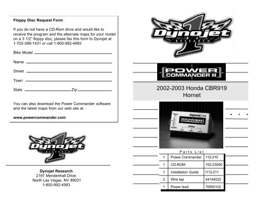
Floppy Disc Request Form<br />
If you do not have a CD-Rom drive and would like to<br />
receive the program and the alternate maps for your model<br />
on a 3 1/2” floppy disc, please fax this form to Dynojet at<br />
1-702-399-1431 or call 1-800-992-4993<br />
Bike Model<br />
Name<br />
Street<br />
Town<br />
State<br />
Zip<br />
<strong>2002</strong>-<strong>2003</strong> <strong>Honda</strong> <strong>CBR919</strong><br />
<strong>Hornet</strong><br />
You can also download the Power Commander software<br />
and the latest maps from our web site at :<br />
www.powercommander.com<br />
Parts List<br />
1 Power Commander 112-210<br />
1 CD-ROM 152-23000<br />
Dynojet Research<br />
2191 Mendenhall Drive<br />
North Las Vegas, NV 89031<br />
1-800-992-4993<br />
1 Installation Guide I112-211<br />
2 Wire tap 44144022<br />
1 Power lead 76950102
Installation Instructions for<br />
<strong>Honda</strong> <strong>CBR919</strong> <strong>Hornet</strong><br />
The ignition MUST be turned off before installation!!<br />
PLEASE READ ALL THE DIRECTIONS BEFORE<br />
STARTING INSTALLATION<br />
1 Remove the seat.<br />
2 Remove the grab rail and tail section by removing the 6<br />
bolts shown in Fig. A.<br />
3 Remove the two pushpins in the front of the tail section.<br />
Squeeze the inside of the pushpin to remove.<br />
Fig.A<br />
Remove these 6 bolts<br />
2
Trouble Shooting<br />
If you feel that you are having any problems at all with the Power<br />
Commander II, disconnect it from your motorcycle. This will allow<br />
the motorcycle to run directly off of the stock ECU.<br />
The lights don’t come on when I turn the ignition switch on.<br />
Check to make sure connectors are seated and the kill switch is in<br />
the “run” position.<br />
4 Remove the two bolts that hold the inner fender to the<br />
frame (Fig. B). There should now be ample room to slide<br />
the ECU out from under the frame.<br />
Fig.B<br />
Wire cluster<br />
The on-board adjustment buttons do not hold their settings.<br />
Be sure to wait 20-30 seconds after making adjustments before<br />
starting or turning off the bike.<br />
Can not upload to or download from the Power Commander II.<br />
Check to see that the serial cable is firmly in place. Verify that<br />
ignition switch is on and the kill switch is in the “run” position.<br />
My mouse uses the same serial port.<br />
If your computer has a PS/2 port purchase a DB9 to PS/2 adapter for<br />
your mouse.<br />
I get a “verify failed....” message when I upload a map to the<br />
Power Commander II.<br />
Programs running in the background or fluctuations in supply voltage<br />
(from outlet) can sometimes cause this error. In most cases, the<br />
information was sent properly to the Power Commander II. Pushing<br />
the “upload all” button again should produce a “tables sent and<br />
verified” message.<br />
Remove these bolts<br />
5 Unplug the black connector from the ECU (Fig. C).<br />
Fig.C<br />
Black connector<br />
I typed in notes, but they didn’t save.<br />
You need to first push the “accept” button in the notes window and<br />
then the “save file” button.<br />
ECU<br />
10 3
6 Connect the PCIII in-line of the stock harness and ECU<br />
(Fig. D).<br />
Fig. D<br />
PCIII connectors<br />
Stock<br />
connector<br />
7 Locate the red wire with a yellow tracer on the grey<br />
connector of the ECU. Crimp the supplied wire tap to this<br />
wire (Fig. E). It is recommended to use dielectric grease.<br />
8 Connect the grey wire from the PCIII to the wire tap (Fig. E)<br />
Fig. E<br />
Hold these buttons<br />
and turn the ignition<br />
on to adjust the<br />
Power Commander III<br />
Red/yellow<br />
wire<br />
Wire tap<br />
Grey wire<br />
from PCIII<br />
4 9
Adjusting Your Power Commander<br />
Your Power Commander has been programmed with a base<br />
map for your application. You can adjust the base map or<br />
install an alternate map using your Computer. Please refer to<br />
the supplied CD-Rom for more information.<br />
You can also adjust your Power Commander using the face<br />
plate buttons as described below.<br />
9 Locate the wire cluster at the rear of the motorcycle. This<br />
cluster contains the connections for the turn signals, tail<br />
light, and license plate light (Fig. B). Unplug the license<br />
plate connector and plug the red connectors from the PCIII<br />
in line (Fig. F).<br />
PCIII power wires<br />
Fig.F<br />
1. With the ignition off, hold down all three buttons on the<br />
Power Commander III unit.<br />
2. While still holding down the buttons, turn the ignition on.<br />
3. Release buttons.<br />
4. Select the range you wish to adjust: Low, Med, High, by<br />
pushing the corresponding button once.<br />
5. At this point holding that button down will move the lights<br />
down ( leaning out the mixture).<br />
Stock connectors<br />
10 Route the ground wire from the PCIII to the negative side<br />
of the battery (Fig. G).<br />
Fig. G<br />
6. Pushing the button repeatedly will move the light up<br />
(richening the mixture).<br />
7. When the two center light are lit up this is the “0” setting.<br />
After making your adjustments wait 20 seconds before starting<br />
the bike or turning it off. This allows the settings to be saved to<br />
memory. To verify that it is safe to start the bike, move the<br />
throttle and watch to see if the lights move up and down the<br />
scale. If they do, you may start or turn off the bike.<br />
Ground wire from PCIII<br />
8 5
11 Slide the ECU back under the frame.<br />
12 Using the supplied velcro install the PCIII onto the frame<br />
rail (Fig. H). Make sure to clean both surfaces with the<br />
alcohol swab before adhering the unit to the frame. You<br />
can check the placement of the unit by installing the seat<br />
for proper fitment.<br />
Fig. H<br />
13 Make sure all wires are routed as they will not get<br />
pinched when the tail section and seat are installed.<br />
14 Install tail section and seat.<br />
6 7
Follow these additional instructions<br />
for European models only.<br />
Fig.J<br />
This end to ECU<br />
1 Plug the supplied power lead to the red wire of the PCIII<br />
(Fig. J).<br />
2 Locate the black wire with a white tracer on the grey<br />
connector side of the ECU (Fig. K).<br />
Connection from<br />
PCIII<br />
3 Connect the supplied wire tap to this wire. Make sure<br />
the tap is completely closed (Fig. K). It is recommended<br />
to use dielectric grease inside this connector.<br />
4 Connect the other end of the power lead to the wire tap<br />
(Fig. K). It is recommended to use dialectric grease on<br />
this connection.<br />
Power for the Power Commander is supplied from the tail light<br />
circuit. On European specification bikes it is possible to switch<br />
the light circuit off (via the handlebar switch). This will shut off<br />
the power to the Power Commander causing the bike to stall.<br />
It is necessary to use the power lead adapter and wire tap on<br />
European bikes to maintain constant power to the Power<br />
Commander. It is not necessary to use these parts on a U.S<br />
specification bike as there is no performance advantage.<br />
Fig.K<br />
Supplied auxiliary<br />
wire<br />
Red wire from<br />
PCIII<br />
Wire tap