HDLCR - Niles Audio
HDLCR - Niles Audio
HDLCR - Niles Audio

You also want an ePaper? Increase the reach of your titles
YUMPU automatically turns print PDFs into web optimized ePapers that Google loves.
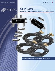
I N S T A L L A T I O N G U I D E<br />
FOR USE IN MULTI-CHANNEL MUSIC OR HOME THEATER SYSTEMS<br />
HIGH DEFINITION, LEFT/CENTER/RIGHT CHANNEL, IN-WALL LOUDSPEAKER<br />
<strong>HDLCR</strong>
CONGRATULATIONS!<br />
Thank you for choosing the <strong>HDLCR</strong> High-Definition, Left/Center/Right Channel In-Wall<br />
Loudspeaker from <strong>Niles</strong>. With proper installation and operation, you should enjoy years of<br />
trouble-free use.<br />
<strong>Niles</strong> manufactures the industry’s most complete line of custom installation components and<br />
accessories for audio/video systems. To see the complete <strong>Niles</strong> product assortment, visit us on<br />
the Internet at: www.nilesaudio.com<br />
TABLE OF CONTENTS<br />
Introduction 1<br />
Features and Benefits 1<br />
Installation Considerations 3<br />
Speaker Placement 6<br />
Installation Fundamentals 9<br />
New Construction: Installing A Bracket 14<br />
Existing Construction: Installing A Bracket 16<br />
Finishing the Installation 17<br />
Operation 22<br />
Removing the Grille and Speaker 22<br />
Specifications 23<br />
Limited Warranty 24<br />
Warranty Registration Card 25
INTRODUCTION<br />
The <strong>Niles</strong> <strong>HDLCR</strong> High-Definition, Left/Center/Right Channel, In-Wall Loudspeaker is expressly<br />
designed for superior sonic quality in front-, center-, or rear-channel applications. It employs<br />
advanced technology components that extract the subtle nuances in recorded music or the thunderous<br />
action sound in a movie. The <strong>HDLCR</strong> is the perfect choice wherever quality of sound is the<br />
most important consideration.<br />
FEATURES AND BENEFITS<br />
INJECTION-MOLDED TCC WOOFERS WITH BUTYL-<br />
RUBBER SURROUND, LONG-THROW VOICE COIL/<br />
MAGNET STRUCTURE, AND VENTED POLE PIECE<br />
The <strong>HDLCR</strong> features newly-developed woofer-cone material that combines injection-molded<br />
polypropylene with talc, carbon, and ceramic (TCC) stiffening agents. As a result, the cone offers<br />
extreme stiffness and light weight for accurate, dynamic response. A long-throw voice coil/magnet<br />
structure ensures increased cone excursion to enhance low frequency response and dynamic<br />
impact. Additionally, each woofer employs a vented pole piece for increased bass linearity and a<br />
butyl-rubber surround for improved midrange damping and clarity as well as moisture resistance.<br />
1-INCH TETERON TRI-LAMINATE TWEETER HOUSED IN A<br />
PRECISION ADJUSTMENT MECHANISM<br />
The <strong>HDLCR</strong>’s Teteron Tweeter employs a tri-laminate design consisting of an inner textile layer,<br />
which forms the dome, a high damping layer to kill unwanted resonances, and an outside layer of<br />
urethane to add stiffness and prevent breakup modes. The result is a transparently clear, sweet,<br />
natural-sounding tweeter, which still maintains extended frequency response. This advanced<br />
tweeter is housed in a precision adjustment mechanism, which permits the tweeter to be accurately<br />
positioned after installation for optimum performance and without the diffraction distortion<br />
typical of traditional pivoting tweeters.<br />
DIRECTED SOUND FIELD GEOMETRY (DSFG) DELIVERS<br />
OPTIMUM PHASE RESPONSE TO LISTENERS AND COM-<br />
PENSATES FOR HIGH SPEAKER PLACEMENT<br />
The <strong>HDLCR</strong> employs <strong>Niles</strong>’ Directed Sound Field Geometry (DSFG). With DSFG, the tweeter is offset<br />
from the center of the dual woofers. The resulting acoustic interaction between the woofers and<br />
the offset tweeter results in the flattest frequency and phase response, approximately 15-degrees<br />
off-axis from the tweeter. This gives optimum performance to a seated listener, even if the loudspeaker<br />
is mounted above a built-in TV.<br />
NILES AUDIO CORPORATION – 1-800-BUY-HIFI<br />
1
INSTALLER-SELECTABLE ACOUSTIC FINE TUNING<br />
Using the baffle-mounted TREBLE and BASS CUT controls, the installer can de-emphasize the bass and/<br />
or treble response by 3 dB after installing the <strong>HDLCR</strong> to precisely tone match the sound in any room.<br />
CTR L/R MODE SWITCH<br />
The <strong>HDLCR</strong> includes a baffle-mounted CTR L/R mode switch to optimize performance in applications<br />
as either a center channel or left/right loudspeaker for front-channel use.<br />
EASY RETROFIT INSTALLATION IN YOUR EXISTING HOME<br />
Designed for ease of installation, the <strong>Niles</strong> mounting system makes retrofit installations simple and<br />
fast. A supplied template assures fast and accurate hole cutting. The bracket slips behind the drywall<br />
and the screws secure the bracket to the frame, sandwiching the drywall between them. The speaker<br />
baffle attaches to the frame, and the grille mounts over the speaker.<br />
THREE-STAGE INSTALLATION SYSTEM FOR REMODELS OR<br />
NEW CONSTRUCTION<br />
Only the parts needed are installed during a particular stage of construction. After framing and wiring<br />
are finished, the bracket is installed. After the drywall is up, but before the painter begins to paint, the<br />
frame is installed, and the rustproof aluminum grille is left for the painter to match to the surroundings.<br />
The speaker is installed only when construction is completely finished. Masking or prepping the<br />
speaker for painting and worries about speaker theft during final construction are never an issue!<br />
MICROPERF ALUMINUM GRILLES<br />
<strong>Niles</strong>’ exclusive MicroPerf grille construction provides an exceptionally tight hole pattern for<br />
acoustic transparency at all audio frequencies and enables the speaker elements to remain invisible.<br />
MicroPerf aluminum grilles can also be painted to blend seamlessly with the surrounding decor.<br />
Additionally, the aluminum grille material will never rust or discolor over time.<br />
INFRARED SENSOR MOUNT<br />
The speaker baffle has a locator designed for the <strong>Niles</strong> MS-100 MicroSensor ® , a miniature infrared<br />
sensor. The MS-100 installs discreetly behind the aluminum grille to minimize wall clutter in the home.<br />
To control the equipment, the listener simply points the remote control at the speaker from up to<br />
15 feet away.<br />
2
NILES’ HD HIGH-DEFINITION VOICE MATCHING<br />
Ensures compatibility with other <strong>Niles</strong> HD High-Definition in-wall, on-wall, and ceiling-mount<br />
models to accommodate a wide range of system designs.<br />
DOLBY ® DIGITAL READY<br />
The <strong>HDLCR</strong> is specifically designed for Home Theater Sound. This model exceeds the specifications<br />
set forth by Dolby Laboratories for the accurate reproduction of Dolby Digital-Encoded Sources.<br />
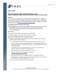
INSTALLATION CONSIDERATIONS<br />
Figure 1. Mounting an <strong>HDLCR</strong><br />
loudspeaker into an wall.<br />
NILES AUDIO CORPORATION – 1-800-BUY-HIFI<br />
Bracket<br />
New Construction Wings<br />
Frame<br />
Acoustic Fine<br />
Tuning Controls<br />
Speaker Baffle<br />
IR Sensor Knockout<br />
Grille<br />
3
4<br />
TOOLS AND PRECAUTIONS<br />
We recommend using the following tools to install a <strong>HDLCR</strong> loudspeaker:<br />
• Electric drill with 1/4- and 1/2-inch drill bits, and a 1-inch flat drill bit<br />
(for drilling through studs)<br />
• Keyhole or drywall saw<br />
• Stiff wire, fish tape, or glow rods (for routing cables)<br />
• Phillips screwdriver set<br />
• Cable ties<br />
• Pencil<br />
• Level<br />
• Rubber gloves and protective eyewear<br />
Before starting the installation, please observe the following precautions:<br />
• Turn off all system power before making any connections.<br />
• Always wear protective eyewear when using tools.<br />
• Make sure hands are clean before installation.<br />
• Wear gloves when working with fiberglass insulation.<br />
RECOMMENDED AMPLIFIER POWER<br />
For satisfactory performance, we recommend using a surround amplifier with a power rating of<br />
10 to 125 watts. Curiously, most loudspeakers are not damaged by large amplifiers, but rather<br />
by small amplifiers. If your system is playing loud music, a small amplifier will run out of power<br />
very quickly and can create damaging “clipping” distortions. A more powerful amplifier will play at<br />
the same volume without distorting. See OPERATION on page 22 for more information about<br />
amplifier clipping distortion.
LOUDSPEAKER WIRE<br />
Use 2-conductor loudspeaker wire when connecting loudspeakers to your receiver or amplifier.<br />
For most applications, we recommend using 16- or 18-gauge wire. For wiring runs longer than 80<br />
feet, we recommend 14-gauge wire. The spring-loaded terminals of the <strong>HDLCR</strong> will accommodate<br />
up to 12-gauge wire directly. Larger sizes can be accommodated via pin connectors.<br />
When running wire inside walls or ceilings, use special jacketed cable (CL-2 or CL-3) to protect the<br />
wire and for fire prevention. In some areas, conduit is also required. For a trouble-free installation,<br />
low-voltage wire such as speaker wire must be run in accordance with the National Electrical Code<br />
and any applicable provisions of the local building code. If you are unsure of the correct installation<br />
techniques, wire jacket, or type of conduit to use, consult a professional audio/video installer,<br />
building contractor, or the local building and inspection department.<br />
INCORPORATING A REMOTE CONTROL<br />
If you are planning to use a stereo system with a hand-held IR remote control, consider the advantages<br />
of having a <strong>Niles</strong> IR Repeater system installed. It will allow you to control all of the functions<br />
of your system from the room with the remote pair of speakers.<br />
<strong>Niles</strong> makes a number of IR sensors, which install in the wall, in the ceiling, in cabinetry, on<br />
tabletops, or even behind the grille of your <strong>Niles</strong> <strong>HDLCR</strong> speaker. An IR sensor requires that a CAT5<br />
cable be home run from each sensor location to the main equipment location. This wire is normally<br />
run beside the speaker wire at the same time. Typically, the sensor is placed in a location that<br />
faces the listening position.<br />
Most remote controls will have an effective line-of-sight range of 18 to 30 feet when used with<br />
any <strong>Niles</strong> sensor placed in a wall, ceiling, on a cabinet or tabletop. However, when a <strong>Niles</strong><br />
MS-100 MicroSensor ® is used behind the <strong>HDLCR</strong>’s perforated aluminum grille, the effective range<br />
is reduced to 9 to 15 feet.<br />
NILES AUDIO CORPORATION – 1-800-BUY-HIFI<br />
5
6<br />
INSULATING THE WALL CAVITY<br />
For best performance from your speakers, fill the wall cavity behind the speaker with fiberglass<br />
insulation (e.g., R-19 un-batted insulation). Try to keep the same amount of insulation for each<br />
speaker, particularly in the same room, for consistent bass response.<br />
SPEAKER PLACEMENT<br />
TECH TIP<br />
Wire size is expressed by its AWG (American<br />
Wire Gauge) number – the lower the number,<br />
the larger the wire. For example, 12 AWG is<br />
physically larger than 14 AWG.<br />
NOTE: THE NILES <strong>HDLCR</strong> LOUDSPEAKER IS DESIGNED FOR USE IN FRONT LEFT-, CENTER-, OR FRONT<br />
RIGHT-CHANNEL APPLICATIONS ONLY. FOR REAR-CHANNEL APPLICATIONS, WE RECOMMEND USING A<br />
NILES HDFX OR CM6HDFX LOUDSPEAKER.<br />
PLACING THE <strong>HDLCR</strong> AS THE FRONT LEFT AND RIGHT<br />
SPEAKERS<br />
In a home theater, the intelligibility of dialog and action reproduced by the front speakers is<br />
paramount! The position of the speakers plays a very important role in how clear the sound is<br />
and how a stereo image is created. Here are some guidelines to make the process of placement<br />
quick and easy:<br />
• Make sure the sound will not be blocked or reflected off furniture or other objects. The<br />
listener should have a direct line of sight with the front of the speaker. To determine<br />
the best position, measure the “listening” distance between the ideal listening position<br />
(e.g., favorite chair or couch) and the wall in which you plan to install the speakers.<br />
• For stereo music applications, try to place the speakers so that they are equally distant<br />
from the listening spot and at least one half of the listening distance apart to maintain<br />
a large pleasant stereo “image.”<br />
• In home theater applications where there is a center channel, you may choose to<br />
space the left and right main speakers farther apart for a “bigger than life” sound with<br />
Dolby ® encoded movies and TV shows. However, for combined music and movie usage,<br />
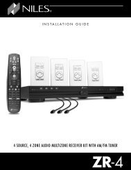
we recommend using the placement zone for stereo music. Ideally, if the listening<br />
position is 10 feet back from the wall, place the speakers between 5 and 10 feet apart,<br />
as shown in Figure 2.
As for placement height, place front left and right speakers on either side of the picture source<br />
so that their tweeters are not more than 24 inches above or below the center-channel speaker’s<br />
tweeter (see Figure 3 on page 8).<br />
NOTE: DO NOT PLACE AN <strong>HDLCR</strong> SPEAKER TOO CLOSE TO A DIRECT-VIEW TV MONITOR, AS IT MAY<br />
CAUSE PICTURE DISCOLORATION. IN GENERAL, TRY TO KEEP IT AT LEAST 24 INCHES AWAY FROM THE<br />
TV. WITH LARGER CRT SCREEN SIZES, TEST THE PLACEMENT DISTANCE FOR PICTURE DEGRADATION<br />
BEFORE INSTALLATION.<br />
THE BOUNDARY EFFECT<br />
Placing a speaker in a corner can powerfully affect the way a listener perceives bass response.<br />
Known as the boundary effect, placing speakers close to a wall/ceiling boundary or near a cornerwall<br />
boundary will emphasize certain bass frequencies, while canceling others. This effect can<br />
make the speaker sound excessively boomy and inaccurate to some listeners, while to others it<br />
just seems like more bass sound.<br />
As a good rule-of-thumb, if you like listening to your current pair of speakers with the bass turned<br />
up, you’ll enjoy corner placement. However, if you listen with the tone controls at neutral, try keeping<br />
the speakers at least 2 or 3 feet from the boundaries of the room.<br />
NILES AUDIO CORPORATION – 1-800-BUY-HIFI<br />
Speaker<br />
Placement<br />
Zone<br />
Speaker<br />
Placement<br />
Zone<br />
Figure 2. Recommended <strong>HDLCR</strong> loudspeaker<br />
placement for front left and right channels.<br />
10' 5' 10'<br />
7
8<br />
PLACING AN <strong>HDLCR</strong> AS THE CENTER-CHANNEL SPEAKER<br />
The center-channel speaker is the workhorse in a home theater system. It handles all of the critical<br />
dialog and is vitally important in creating the illusion of sounds emanating directly from the picture.<br />
Here are some tips for obtaining optimum center-channel performance:<br />
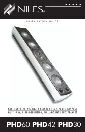
• In a typical installation, place the <strong>HDLCR</strong> horizontally, directly above the television or<br />
projection screen. Try to insure that the speaker is not placed too high relative to the<br />
left and right speaker, as shown in Figure 3.<br />
<strong>HDLCR</strong><br />
TV<br />
Not Greater<br />
than 24"<br />
Not Greater<br />
than 24"<br />
<strong>HDLCR</strong> <strong>HDLCR</strong><br />
<strong>HDLCR</strong><br />
Figure 3. If the <strong>HDLCR</strong> is placed above a TV, install the speaker with the tweeter up. If it is<br />
placed below a TV, install the <strong>HDLCR</strong> with the tweeter down.
• For installations where a perforated projection screen will be used, place the <strong>HDLCR</strong>,<br />
either horizontally or vertically, behind the screen at ear level, as shown in Figure 4.<br />
<strong>HDLCR</strong><br />
Figure 4. Recommended <strong>HDLCR</strong> center-channel placement behind a perforated<br />
projection screen.<br />
INSTALLATION FUNDAMENTALS<br />
RUNNING THE SPEAKER WIRE IN NEW CONSTRUCTION<br />
IMPORTANT: IF YOU HAVE DOUBTS ABOUT WHETHER YOU ARE CAPABLE OF INSTALLING A NILES<br />
CEILING-MOUNT LOUDSPEAKER, PLEASE CONSULT A NILES DEALER OR PROFESSIONAL INSTALLER.<br />
THEY HAVE SPECIAL TOOLS, TECHNIQUES, AND EXPERIENCE TO MAKE THE IMPOSSIBLE JOB<br />
POSSIBLE. THE INSTALLER CAN PROVIDE YOU WITH AN ESTIMATE BEFORE ANY WORK IS DONE.<br />
OBSERVE SAFETY FIRST!<br />
• Always wear gloves, safety goggles, and head protection gear when drilling or<br />
cutting holes.<br />
• Avoid drilling near nails – they ruin bits and can cause injury.<br />
• Be careful using “hole-hogs” and other powerful electric drills. The torque of this<br />
drill when suddenly stopped by a nail can break the wrist of a strong man.<br />
NILES AUDIO CORPORATION – 1-800-BUY-HIFI<br />
Perforated Screen<br />
<strong>HDLCR</strong> <strong>HDLCR</strong><br />
9
RUNNING THE SPEAKER WIRE IN NEW CONSTRUCTION<br />
(CONTINUED)<br />
SCHEDULING AND PREPARATION<br />
Plan to schedule the speaker wiring after the electrical wiring is finished. That way you can avoid<br />
wire routes, which could potentially induce hum over the speaker wire. The basic wiring rules are:<br />
• Never run speaker wire through the same hole as an electrical cable.<br />
• Never run speaker wire into the same J-box as electrical cable.<br />
• Avoid running the speaker wire beside the electrical cable. Keep your speaker<br />
cable at a distance of at least 18 to 22 inches from any electrical power cable.<br />
• If side-by-side wiring is unavoidable in particular spots in the house, move the<br />
speaker wire route away as soon as possible.<br />
• If construction forces a side-by-side run for more than 10 feet, install metal conduit<br />
or shielded speaker wire. Low-voltage wires such as doorbells, intercoms, telephone,<br />
security, or television cannot cause interference or hum on your speaker wires, so<br />
you can safely run all of them at the same time, through the same holes,<br />
side-by-side.<br />
• Before drilling any holes, mount the speaker brackets in the desired speaker<br />
Locations and mount p-rings or open-backed J-boxes where the in-wall volume<br />
Controls and stereo equipment will be located.<br />
ABOUT DRILLING<br />
Use a bit that is large enough for the wires you plan to<br />
run. This is an important consideration, since you may<br />
be drilling a lot of holes. Here are some additional tips:<br />
10<br />
• We recommend using an auger bit for roughin<br />
wiring. It will actually pull itself through<br />
the wood, so that the drill motor, not you,<br />
does most of the work.<br />
• Always drill the holes in the center of the<br />
stud. If you have to notch the stud or drill the<br />
hole closer than 1 inch from the edge of the<br />
stud, protect the wire with a nail plate, as<br />
shown in Figure 5.<br />
Figure 5. Installing a nail<br />
plate to protect wiring in a<br />
notched stud.
• When drilling holes in ceiling joists, drill in the center of the joists and try to locate<br />
the hole near the end of the joist.<br />
IMPORTANT: DO NOT DRILL THROUGH A GLU-LAM OR LOAD-BEARING BEAM WITHOUT THE<br />
DIRECTION OF YOUR CONTRACTOR.<br />
• Try to line the holes up perfectly, because it makes pulling the wire much easier. A<br />
good technique is to snap a chalk line across the face of the studs or against the<br />
bottom of the ceiling joists. Then work backward so that you can always see the<br />
holes you have already drilled. Paying careful attention to this will save you time<br />
later on.<br />
PULLING THE CABLE<br />
Pull the cable in sections (from the stereo to the volume control, from the volume control to the<br />
speaker). Start with the longest sections and use leftover wire to complete the short sections. Also<br />
consider the following wiring tips:<br />
• If you plan to pull many rooms at the same time through a central route, walk off the<br />
Distance to each destination, add a generous “fudge factor” for turns and other<br />
Obstacles, and then cut off each section, so you can pull a bundle of wires at once.<br />
• When running the wire further than 4-1/2 feet from a hole in a stud or joist (e.g., open<br />
attic space, going up walls, etc.), be sure to fasten the wire to the joists or studs using<br />
cable clamps or appropriately-sized wire staples. The wire should not have large sags<br />
in it, nor should it be too tight.<br />
• Try to protect the wire from being stepped on in attics or other unfinished crawl<br />
spaces. Use guard strips, raceways, or conduits to protect the cable. Consult the local<br />
building code for special requirements in your area.<br />
CONCEALING SPEAKER WIRE<br />
ABOUT INTERIOR WALLS<br />
Interior walls in almost all North American residences are hollow, so they are easy installation sites<br />
for flush mounting speakers and routing new speaker cable in the house. Looking at a painted<br />
wallboard, plaster, or paneling, you only see the skin of the wall. Behind it is the home’s skeleton;<br />
2-by-4 inch wood or metal “studs” running vertically from the floor to the ceiling in walls and<br />
2-by-6 inch or larger “joists” running horizontally in the ceilings and floors. The space between the<br />
studs and joists is used for the home’s wiring and plumbing.<br />
NILES AUDIO CORPORATION – 1-800-BUY-HIFI<br />
(CONTINUED ON NEXT PAGE)<br />
11
12<br />
CONCEALING SPEAKER WIRE (CONTINUED)<br />
ABOUT EXTERIOR WALLS<br />
Concealing wires in exterior walls is more complex, since the walls are stuffed with insulation to<br />
protect the house from the heat and cold outside. Moreover, our national building code requires<br />
that a horizontal stud placed between the vertical studs break the hollow wall space in exterior<br />
walls. This “fire blocking” makes it very difficult to retrofit long lengths of wire. In some areas<br />
of the country, the exterior walls are constructed of solid masonry and have no hollow space for<br />
speakers or wires.<br />
PLANNING THE SPEAKER WIRE ROUTE<br />
Start by examining all the possible routes you might take to run the speaker wire from the speaker<br />
to the home theater system. Use a stud sensor or other device to locate the internal structure of the<br />
wall. You will want to avoid all studs or joists. Figure 6 shows a typical wire run from the speaker<br />
location in the ceiling, across the attic, then down through a top plate (i.e., the horizontal 2-by-4<br />
or 2-by-6 inch wood laid across the vertical studs) to a wall plate or a J-Box in the wall behind the<br />
home theater system itself.<br />
Figure 6. Running<br />
speaker wire from a<br />
ceiling speaker to a home<br />
theater system location.<br />
Find all the locations of your existing<br />
electrical, phone, and TV wiring,<br />
and then plan the speaker wire<br />
route to avoid them. Crossing wire<br />
paths is acceptable, but 60 Hz hum<br />
may be induced in the reproduced<br />
audio, if speaker wire is run parallel<br />
to electrical wire for more than<br />
Speaker<br />
Location<br />
Volume<br />
Control<br />
Location<br />
Stereo<br />
Location<br />
a few feet. If possible, try to keep speaker wire away from parallel power cables by at least 3 feet.<br />
To find exactly where an electrical cable is routed, try inspecting the inside of the wall by turning<br />
off the breaker for a particular power outlet or switch, removing the cover plate and switch or<br />
receptacle, and then shining a penlight into the wall. If you have access to an attic or basement<br />
space, you can quickly see which part of the wall space is free of obstructions, as shown in Figure 7.
Figure 7. An example of<br />
unobstructed wall space for<br />
speaker wiring.<br />
When you don’t have access above or below the wall, try to estimate the existing wire and pipe<br />
locations from known positions of electrical outlets and plumbed fixtures on both sides of the wall.<br />
Take a look at the outside of your house too – sometimes conduit, vents, or drainpipe will provide<br />
useful visible clues. Choose the route with the fewest potential obstacles.<br />
If the home is built on a slab, or a speaker wire route is planned between two finished floors, look<br />
for baseboards that could be removed for wire placement. Doorjambs can also be removed and<br />
often have enough space for speaker wire all the way around the door, as shown in Figure 8.<br />
OTHER POSSIBLE SPEAKER WIRE ROUTES INCLUDE:<br />
• Under-the-carpet runs using flat speaker wires.<br />
• Heating and air conditioning vents used as wire raceways for plenum-rated wire.<br />
NOTE: CHECK YOUR LOCAL BUILDING CODES, SINCE SOME MUNICIPALITIES REQUIRE CONDUIT.<br />
NILES AUDIO CORPORATION – 1-800-BUY-HIFI<br />
Figure 8. Running speaker wire<br />
between a wall and a removed<br />
doorjamb. Nail plates are also<br />
installed to protect the wire when<br />
the doorjamb is replaced.<br />
(CONTINUED ON NEXT PAGE)<br />
13
14<br />
CONCEALING SPEAKER WIRE (CONTINUED)<br />
CUTTING HOLES<br />
In traditional wood stud/drywall construction,<br />
first cut the hole for the speaker.<br />
Then, in the opening, use a drill with a<br />
long bit to auger a wire route up or down<br />
the wall. Next, cut a hole in the drywall for<br />
stud access, drill holes through the studs,<br />
and run your wire, as shown in Figure 9.<br />
After the wire has been run, patch the hole<br />
with the cut drywall using standard drywall<br />
joint tape and joint compound. Let the<br />
patch dry, sand the surface, and touch-up<br />
the wall with paint.<br />
NOTE: BE PATIENT WITH UNKNOWN<br />
STRUCTURES OR DIFFICULT-TO-PATCH<br />
WALL MATERIALS LIKE PLASTER, LATH<br />
AND PLASTER, FAUX FINISHES, WALLPAPER<br />
ETC. ALWAYS PERFORM A CAREFUL STUDY<br />
OF THE POTENTIAL PROBLEMS BEFORE<br />
STARTING THE JOB.<br />
NEW CONSTRUCTION: INSTALLING A BRACKET<br />
The hole-saving bracket enables a faster and cleaner final installation of the speaker. It forces the<br />
drywall installer to cut out the speaker hole for you and provides wire ties for the speaker wire,<br />
reducing the risks of accidental loss or movement of the wire. In addition, it enables you to align<br />
your speakers with other ceiling fixtures with greater accuracy, since you can see exactly where<br />
the speaker will be.<br />
INSTALLING THE BRACKET<br />
Figure 9. Example of a<br />
wall speaker cutout with<br />
studs drilled for wire run.<br />
1. Attach the QuickSnap new-construction wings to the bracket by snapping them into<br />
the bracket sides. If the length will interfere with corner or eaves, shorten the wings by<br />
breaking them along the scored lines. You can mount the bracket horizontally or vertically,<br />
as shown in Figure 10.
2. Screw one side of the assembled bracket with wings to the stud or joist, using one<br />
of the supplied screws. Level the bracket, and then screw the other side of the<br />
bracket/wing assembly to the stud or joist. Two screws on each side make for a<br />
very secure installation.<br />
3. Attach the wire to the bracket at the indicated<br />
wire tie points, as shown in Figure 10.<br />
CONCEALING SPEAKER WIRE FOR<br />
A FUTURE INSTALLATION<br />
1. Attach the speaker wire in a loop between the<br />
ceiling joists and carefully mark the<br />
exact location of the wire on a set of plans.<br />
2. Ask the general contractor to inform the drywall<br />
installers that the speaker wire loops are<br />
concealed for future installations, as shown in<br />
Figure 11.<br />
NILES AUDIO CORPORATION – 1-800-BUY-HIFI<br />
4 Wire Ties<br />
Figure 10. The hole-saving brackets with QuickSnap new-construction wings can be installed<br />
horizontally or vertically.<br />
Figure 11. The speaker wire<br />
is looped and hung on two nails<br />
attached to the joists, securing it<br />
for future use. Be sure to note the<br />
location on house plans.<br />
15
EXISTING CONSTRUCTION: INSTALLING A BRACKET<br />
IMPORTANT: BEFORE YOU CUT INTO ANY WALL, REVIEW THE SECTIONS ON SPEAKER<br />
PLACEMENT ON PAGE 6 AND RUNNING THE SPEAKER WIRE IN NEW CONSTRUCTION ON<br />
PAGE 9. BE SURE NOT TO DRILL OR CUT THROUGH EXISTING WIRES, PIPES, OR STRUCTURE.<br />
IF YOU FEEL ANY EXTRA RESISTANCE AS YOU ARE DRILLING OR SAWING, STOP!<br />
1. Locate studs or joists by using a stud sensor or by hand knocking. Do not place the<br />
edge of the cutout directly next to a stud or joist, since the frame and bracket will<br />
extend beyond the cutout.<br />
16<br />
2. At the planned cutout site, drill a 1/8-inch pilot hole just barely through the wall, about<br />
an inch below the center of your proposed speaker location.<br />
NOTE: IN MOST HOMES, THE WALL THICKNESS IS 1/2 TO 5/8 INCH.<br />
3. Cut a foot-long piece of coat hanger and bend it to create a right angle. Poke the<br />
“L-shaped” wire into the pilot hole and turn it in a<br />
complete circle, as shown in Figure 12.<br />
4. Continue turning the coat hanger as you move it<br />
into the cavity to a depth of approximately<br />
4 inches. If you feel an obstruction, fill the hole(s)<br />
with spackling compound and repeat steps<br />
1 through 4 at a new location.<br />
5. If the coat hanger moves freely in a complete circle,<br />
hold the supplied template up to the wall or ceiling<br />
and level it in the horizontal or vertical position. Use<br />
a pencil to outline the cutout on the surface and<br />
then drill the four corner holes with a 1/4-inch bit<br />
(see Figure 13 on page 17).<br />
Figure 12. Using a coat<br />
hanger to check for obstructions<br />
behind the wall speaker site.<br />
6. If you are cutting drywall, use a sheetrock or keyhole saw. Cut the outline with the saw<br />
at a 45-degree angle. That way, the drywall section can be replaced cleanly if there is<br />
an unseen obstruction behind the wall.<br />
7. If you are cutting into a plaster ceiling, use masking tape to outline the penciled opening<br />
and use a razor to score the plaster down to the lath beneath. Then use a chisel to<br />
remove all of the plaster within the taped outline. To actually cut the lath, consider the<br />
following two professional methods:<br />
• Use a saber saw with a metal cutting blade for the quickest cut. However, sawing<br />
lath with a saber saw can easily vibrate plaster off the ceiling in a completely distant<br />
location, thereby creating more patchwork.<br />
• If you have the patience, use a pair of tin snips to slowly nip away at the lath instead.<br />
There is little risk with this method – it is just more time consuming.
FINISHING THE INSTALLATION<br />
PAINTING THE GRILLE AND FRAME<br />
After drywall is up, each <strong>HDLCR</strong> frame and grille may be painted without the need for primer. For<br />
best results, use a spray gun or airless sprayer, thin the paint to prevent clogging of the grille holes,<br />
and apply several light coats instead of one heavy one.<br />
1. Paint each grille and let it dry before installation.<br />
2. Paint each frame and let it dry before installation.<br />
INSTALLING THE FRAME<br />
1. Fill each wall cavity with insulation. Remember to use equal amounts of insulation for<br />
each speaker.<br />
2. For existing construction, slip the mounting bracket through the hole and pull it toward<br />
you so that its front edge slides into the hole and stops in place.<br />
NOTE: FOR NEW CONSTRUCTION, THE MOUNTING BRACKET SHOULD ALREADY BE IN PLACE<br />
(AS DESCRIBED IN THE SECTION “NEW CONSTRUCTION: INSTALLING A BRACKET” ON PAGE 14.<br />
3. Attach each frame to its bracket<br />
using the supplied screws, as<br />
shown in Figure 13. The screws<br />
should pull the frame and<br />
bracket together (sandwiching<br />
the drywall) so that the<br />
frame is absolutely flush<br />
with the wall surface.<br />
There should be no<br />
gaps between the<br />
wall and the frame.<br />
IMPORTANT: DO NOT<br />
OVER TIGHTEN THE<br />
SCREWS! OVER TIGHTENING<br />
THEM MAY MAKE<br />
THE GRILLE DIFFICULT<br />
TO INSTALL.<br />
NILES AUDIO CORPORATION – 1-800-BUY-HIFI<br />
Figure 13. Installing the<br />
frame into a mounting bracket.<br />
17
18<br />
INSTALLING A NILES MS-100 MICROSENSOR ®<br />
1. For each speaker, locate the half-inch round, molded “IR Sensor Knockout”<br />
on the baffle.<br />
2. Lay each speaker face down on a clean carpet or rug. Put the tip of a screwdriver<br />
into the center of the round “knockout” and sharply tap the screwdriver handle<br />
as necessary.<br />
NOTE: TO PREVENT DAMAGE TO THE CROSSOVER NETWORK, ALWAYS REMOVE A KNOCKOUT<br />
FROM THE REAR OF THE SPEAKER. DO NOT ATTEMPT TO REMOVE A KNOCKOUT WITH THE<br />
SPEAKER FACE UP.<br />
3. At each speaker, install the MS-100 (using its mounting hex nut and washer) until it is<br />
tightly secured.<br />
4. Connect all MS-100 wires.<br />
SETTING THE CTR L/R MODE<br />
The <strong>HDLCR</strong> includes a baffle-mounted CTR L/R mode switch to optimize performance in<br />
applications as either a center channel or left/right loudspeaker for front-channel use, as shown<br />
in Figure 14.<br />
• For front left- or right-channel applications, slide the <strong>HDLCR</strong>’s mode switch to L/R.<br />
• For center-channel use, slide the <strong>HDLCR</strong>’s mode switch to CTR.<br />
CTR L/R<br />
Figure 14. The <strong>HDLCR</strong>’s CTR L/R mode switch.
CONNECTING AND INSTALLING THE SPEAKER<br />
1. At each speaker, separate the speaker wire so that at least 2 inches of each conductor<br />
are free. Strip away 1/4 inch of insulation from each speaker wire.<br />
2. On each set of speaker connectors, press down the spring-loaded lever, insert the appropriate<br />
conductor, and then release the lever, as shown in Figure 15. Gently tug on<br />
the speaker wire to make sure it is held in place. If not, repeat this procedure until it is.<br />
NOTE: OBSERVE CORRECT POLARITY: POSITIVE (+) GOES INTO THE RED TERMINAL AND<br />
NEGATIVE (–) GOES INTO THE BLACK TERMINAL.<br />
3. Connect the other end of each speaker wire to the receiver (or amplifier) in the same<br />
way. If you are unsure of wire polarity, see the next section, Checking Speaker Phase<br />
on page 20.<br />
NOTE: OBSERVE CORRECT POLARITY: POSITIVE (+) GOES INTO THE RED TERMINAL AND<br />
NEGATIVE (–) GOES INTO THE BLACK TERMINAL.<br />
4. Install the speaker baffle into its frame by inserting the tabs at the base into the corresponding<br />
holes in the frame and pushing the speaker forward until the snaps engage,<br />
as shown in Figure 16.<br />
NILES AUDIO CORPORATION – 1-800-BUY-HIFI<br />
CTR L/R<br />
Figure 16. Installing the speaker baffle into its frame.<br />
Figure 15. Connecting a speaker<br />
wire to the <strong>HDLCR</strong> terminals.<br />
(CONTINUED ON NEXT PAGE)<br />
19
CONNECTING AND INSTALLING THE SPEAKER (CONTINUED)<br />
IMPORTANT: WHEN INSTALLING THE SPEAKERS IN THE CEILING, OR IF THE INSTALLATION IS<br />
IN AN EARTHQUAKE ZONE, WE RECOMMEND USING THE ENCLOSED SHEET METAL SCREWS TO<br />
SECURE THE BAFFLE TO THE FRAME AS FOLLOWS:<br />
a. Locate the dimples on the front baffle.<br />
b. Place the self-tapping sheet-metal screw in the dimple and turn it with a screwdriver<br />
until it cuts through the baffle and anchors securely in the frame, as shown in<br />
Figure 17.<br />
5. Turn on the home theater receiver and calibrate all speakers in the system according to<br />
the receiver manufacturer’s instructions.<br />
CHECKING SPEAKER PHASE<br />
Speaker wire has two conductors. On both your speaker and amplifier, one conductor is attached to<br />
the negative (–) terminals, while the other is attached to the positive (+) terminals. Usually, the wire<br />
is marked for your convenience, but the marking can be done in the following different ways:<br />
• Stripe on one wire<br />
• Ribbed area you can feel on one conductor<br />
• Different colors of metal wire on each conductor<br />
• Fabric strand or string wound into one of the conductors<br />
Of course, there are some wires that appear completely identical. So be careful, or you might make<br />
a connection mistake. If you do, one speaker will be playing “out-of-phase” with the other speaker.<br />
A pair of out-of-phase speakers works against each other, and the sound of the two playing together<br />
will be lacking in bass and sound “phasey.” If you suspect the sound is not right, and you cannot see<br />
any markings on the wire, try this simple test:<br />
20<br />
Figure 17. Inserting the speaker baffle<br />
into its frame with sheet-metal screws.
1. Stand halfway between the speakers.<br />
2. Play some music with the amplifier or radio set to Mono.<br />
3. Listen to the richness of the bass and the loudness of the sound.<br />
4. Turn off the amplifier and reverse the connections on one amplifier channel only.<br />
5. Repeat the listening test with the same volume control setting. When the sound has a<br />
richer bass and is slightly louder, the speakers are working together or “in-phase.”<br />
ACOUSTIC FINE TUNING<br />
Each <strong>HDLCR</strong> speaker features separate, baffle-mounted TREBLE CUT and BASS CUT controls for<br />
acoustic fine-tuning after installation, as shown in Figure 18.<br />
• If a <strong>HDLCR</strong> is placed near a boundary, set its<br />
BASS CUT switch to – 3 dB to lower the bass<br />
response.<br />
• If a <strong>HDLCR</strong> is placed in a room with highly<br />
reflective surfaces like glass or tile, set its<br />
TREBLE CUT switch to – 3 dB to lower the<br />
high-frequency response.<br />
ADJUSTING THE TWEETER<br />
The <strong>HDLCR</strong> tweeter is housed in a precision adjustment mechanism which enables precise aiming<br />
of the directional high frequencies to provide optimum performance. To adjust the tweeter:<br />
1. Carefully grasp the tweeter housing by placing your<br />
thumb and forefinger in the indentations provided.<br />
2. Rotate the tweeter housing either clockwise or counter-clockwise<br />
as required. The mechanism is indexed<br />
at equal intervals so that speakers in a pair can be<br />
adjusted equally. Simply count the number of “clicks”<br />
as the first tweeter is adjusted. Repeat the process<br />
for the second speaker, rotating the tweeter the<br />
same number of “clicks” in the opposite direction, as<br />
shown in Figure 19.<br />
NILES AUDIO CORPORATION – 1-800-BUY-HIFI<br />
Figure 18. The <strong>HDLCR</strong>’s TREBLE<br />
and BASS CUT switches.<br />
Figure 19. Rotating the<br />
<strong>HDLCR</strong>’s tweeter.<br />
(CONTINUED ON NEXT PAGE)<br />
21
ADJUSTING THE TWEETER (CONTINUED)<br />
3. Pivot the tweeter on each speaker equally<br />
by depressing the housing at the arrows<br />
until the desired angle is achieved, as<br />
shown in Figure 20.<br />
INSTALLING THE GRILLE<br />
At each speaker, carefully fit the grille into its recess<br />
so that it is barely in place. Starting with one corner,<br />
gently press the grille around the speaker, pushing<br />
it in a little bit each time. Be gentle – the aluminum<br />
grille can be easily bent out of shape. When properly<br />
installed, the grille will be absolutely flush in<br />
appearance with the surrounding frame.<br />
OPERATION<br />
LISTENING AT HIGHER VOLUMES<br />
Achieving a reasonable volume of sound in a large room requires more amplifier power than it does<br />
in a small room. It is possible to turn the volume up so high that the amplifier runs out of power.<br />
This creates “clipping” distortion, which will make treble sound very harsh and unmusical.<br />
When you hear harsh-sounding treble from any good speaker, turn the volume down immediately!<br />
Those harsh sounds are masking much more powerful ultra-high-frequency sound spikes, which<br />
will quickly damage any fine loudspeaker. You are much less likely to damage a speaker driven by a<br />
large amplifier because it will be very loud before any clipping distortion is produced.<br />
CLEANING<br />
Clean the <strong>Niles</strong> <strong>HDLCR</strong> loudspeaker with a dampened soft cloth or paper towel. If the speaker is<br />
mounted high up on a wall or ceiling, use a broom to gently brush it off.<br />
REMOVING THE GRILLE AND SPEAKER<br />
REMOVING THE GRILLE<br />
If you need to remove an installed grille, use a bent paper clip or the tip of a corkscrew to gently<br />
pull it away from the frame.<br />
22<br />
Figure 20. Pivoting the <strong>HDLCR</strong>’s tweeter.
REMOVING THE SPEAKER<br />
After removing the grille, use two small screwdrivers (or needle-nose pliers) to release the snaps<br />
that hold the speaker (and baffle) to the frame. Insert the screwdrivers into the holes in the snaps<br />
and exert force straight down (towards the woofer) until the snaps release, as shown in Figure 21.<br />
Once the snaps release, the speaker can be tilted away from the frame to be removed.<br />
NOTE: DO NOT ATTEMPT TO USE THE FRAME FOR LEVERAGE, AS THIS MAY DAMAGE THE SURFACE OF<br />
THE FRAME.<br />
SPECIFICATIONS<br />
Figure 21. Removing the <strong>HDLCR</strong> speaker baffle from its frame.<br />
Recommended Amplifier Power Nominal Impedance<br />
10 to 150 watts per channel 4 ohms<br />
Frequency Response Sensitivity<br />
65 Hz to 21 kHz, +/- 3 dB 89 dB with 2.83 V pink noise input,<br />
measured at 1 meter on axis<br />
Frame Dimensions Hole Cut-Out Dimensions<br />
8-1/4" x 14-1/2" 7-1/8" x 13-1/4"<br />
Depth Behind Wall<br />
3-1/2" (based on 1/2" drywall)<br />
Wiring Requirements<br />
We recommend using 16- to 18-gauge speaker wire for runs up to 80 feet and<br />
14-gauge speaker wire for runs up to 200 feet. The connectors will accommodate<br />
12- to 22-gauge wire.<br />
NILES AUDIO CORPORATION – 1-800-BUY-HIFI<br />
1-800-BUY-HIFI<br />
1-800-289-4434<br />
www.nilesaudio.com<br />
1-800-BUY-HIFI<br />
1-800-289-4434<br />
www.nilesaudio.com<br />
23
LIMITED WARRANTY<br />
NILES AUDIO CORPORATION (“NILES”) WARRANTS ITS LOUDSPEAKER PRODUCTS TO THE ORIGINAL PURCHASER TO<br />
BE FREE OF MANUFACTURING DEFECTS IN MATERIAL AND WORKMANSHIP FOR A PERIOD OF FIVE YEARS FROM<br />
DATE OF PURCHASE.<br />
THIS WARRANTY IS SUBJECT TO THE FOLLOWING ADDITIONAL CONDITIONS AND LIMITATIONS. THE WARRANTY<br />
IS VOID AND INAPPLICABLE IF NILES DEEMS THAT THE PRODUCT HAS BEEN USED OR HANDLED OTHER THAN IN<br />
ACCORDANCE WITH THE INSTRUCTIONS PROVIDED BY THE MANUFACTURER, INCLUDING BUT NOT LIMITED TO<br />
DAMAGE CAUSED BY ACCIDENT, MISHANDLING, IMPROPER INSTALLATION, ABUSE, NEGLIGENCE, OR NORMAL<br />
WEAR AND TEAR, OR ANY DEFECT CAUSED BY REPAIR TO THE PRODUCT BY ANYONE OTHER THAN NILES OR AN<br />
AUTHORIZED NILES DEALER.<br />
TO OBTAIN WARRANTY SERVICE, TAKE THE UNIT TO THE NEAREST AUTHORIZED NILES DEALER, WHO WILL<br />
TEST THE PRODUCT AND IF NECESSARY, FORWARD IT TO NILES FOR SERVICE. IF THERE ARE NO AUTHORIZED<br />
NILES DEALERS IN YOUR AREA, YOU MUST WRITE TO NILES AND INCLUDE YOUR NAME, ADDRESS, MODEL AND<br />
SERIAL NUMBER OF YOUR UNIT, ALONG WITH A BRIEF DESCRIPTION OF THE PROBLEM. A FACTORY RETURN<br />
AUTHORIZATION NUMBER WILL BE SENT TO YOU. DO NOT RETURN ANY UNIT WITHOUT FIRST RECEIVING WRITTEN<br />
AUTHORIZATION AND SHIPPING INSTRUCTIONS FROM NILES.<br />
IF THE ABOVE CONDITIONS ARE MET, THE PURCHASER’S SOLE REMEDY SHALL BE TO RETURN THE PRODUCT TO<br />
NILES, IN WHICH CASE NILES WILL REPAIR OR REPLACE, AT ITS SOLE OPTION, THE DEFECTIVE PRODUCT WITHOUT<br />
CHARGE FOR PARTS OR LABOR. NILES WILL RETURN A UNIT REPAIRED OR REPLACED UNDER WARRANTY BY<br />
SHIPPING SAME BY ITS USUAL SHIPPING METHOD FROM THE FACTORY (ONLY) AT ITS EXPENSE WITHIN THE<br />
UNITED STATES OF AMERICA. THERE ARE NO OTHER WARRANTIES, INCLUDING WITHOUT LIMITATION, EITHER<br />
EXPRESS OR IMPLIED WARRANTIES OF MERCHANTABILITY OR FITNESS FOR A PARTICULAR PURPOSE, WITH<br />
RESPECT TO THE PRODUCT.<br />
REPAIR OR REPLACEMENT AS PROVIDED UNDER THIS WARRANTY IS THE EXCLUSIVE REMEDY OF THE CONSUMER/<br />
PURCHASER. NILES SHALL NOT BE RESPONSIBLE FOR ANY INCIDENTAL OR CONSEQUENTIAL DAMAGES EXCEPT TO<br />
THE EXTENT PROVIDED (OR PROHIBITED) BY APPLICABLE LAW.<br />
SOME STATES DO NOT ALLOW THE EXCLUSION OR LIMITATION OF INCIDENTAL OR CONSEQUENTIAL DAMAGES,<br />
SO THE ABOVE LIMITATION MAY NOT APPLY TO YOU. THIS WARRANTY GIVES YOU SPECIFIC LEGAL RIGHTS, AND<br />
YOU MAY ALSO HAVE OTHER RIGHTS WHICH VARY FROM STATE TO STATE.<br />
FOR THE NAME OF YOUR NEAREST AUTHORIZED NILES DEALER CONTACT:<br />
NILES AUDIO CORPORATION, P.O. BOX 160818, MIAMI, FLORIDA 33116-0818.<br />
24<br />
Please fill in your product information and retain for your records.<br />
Model______________________ Serial No.___________________ Purchase Date_______
DETACH HERE AND RETURN TO: NILES AUDIO CORPORATION WARRANTY REGISTRATION DEPT. P.O. BOX 160818 MIAMI, FLORIDA 33116-0818<br />
WARRANTY REGISTRATION CARD<br />
Model Purchased_________________________________________________________<br />
Serial Number___________________________________________________________<br />
Date Purchased (month/day/year)_____________________________________________<br />
Dealer Name and Location__________________________________________________<br />
______________________________________________________________________<br />
❍ Dr. ❍ Miss ❍ Mr. ❍ Mrs. ❍ Ms.<br />
Name__________________________________________________________________<br />
Address__________________________________________________________________<br />
____________________________________________________________________<br />
City_______________________________________State________________Zip______<br />
Telephone ( )__________________________________________________<br />
Please take a moment to fill out our warranty registration card. The information helps us to get to<br />
know you better and develop the products you want<br />
Age:<br />
❍ Under 25<br />
❍ 25-34<br />
❍ 35-44<br />
❍ 45-54<br />
❍ 55 & over<br />
Income:<br />
❍ Under $24,999<br />
❍ $25,000-$34,999<br />
❍ $35,000-$44,999<br />
❍ $45,000-$59,999<br />
❍ $60,000-$74,999<br />
❍ $75,000-$99,999<br />
❍ Over $99,999<br />
Occupation:<br />
❍ Arts/Entertainment<br />
❍ Business Owner<br />
❍ Engineer<br />
❍ Finance/Accounting<br />
❍ General Office<br />
❍ Management<br />
❍ Professional<br />
❍ Sales/Marketing<br />
❍ Student<br />
❍ Tradesperson<br />
Musical tastes:<br />
(Please check<br />
all that apply)<br />
❍ Alternative<br />
❍ Classical<br />
❍ Country<br />
❍ Jazz<br />
❍ New Age<br />
❍ Popular<br />
❍ R&B<br />
❍ Rock<br />
❍ Other _____________<br />
How did you hear<br />
about <strong>Niles</strong>?<br />
❍ Architect/Developer<br />
❍ Custom Installer<br />
❍ Direct Mail<br />
❍ Friend/Family<br />
❍ In-Store Display<br />
❍ Interior Designer<br />
❍ Magazine Ad<br />
❍ Mail-Order Catalog<br />
❍ Newspaper Ad<br />
❍ Product Brochure<br />
❍ Product Review<br />
❍ Retail Salesperson<br />
What magazines<br />
do you read?<br />
1. ________________<br />
2. ________________<br />
3. ________________<br />
Who will install<br />
the product?<br />
❍ Custom Installer<br />
❍ Electrician<br />
❍ Friend<br />
❍ Myself<br />
Which factor(s) influenced<br />
the purchase of your <strong>Niles</strong><br />
product? (Please check<br />
all that apply)<br />
❍ Ease of Use<br />
❍ Price/Value<br />
❍ Product Features<br />
❍ Quality/Durability<br />
❍ Reputation<br />
❍ Style/Appearance<br />
❍ Warranty<br />
Do you . . . ?<br />
❍ Own a House. If yes,<br />
how many square feet?<br />
❍ Own a Town House/<br />
Condominium/Co-op<br />
❍ Rent an Apartment<br />
❍ Rent a House<br />
Are you interested in<br />
receiving literature on<br />
other <strong>Niles</strong> products?<br />
❍ Yes ❍ No<br />
Are there products/<br />
capabilities that you would<br />
like to see introduced?
B L E N D I N G H I G H F I D E L I T Y A N D A R C H I T E C T U R E ®<br />
N i l e s A u d i o C o r p o r a t i o n<br />
1 2 3 3 1 S . W . 1 3 0 S t r e e t M i a m i , F l o r i d a 3 3 1 8 6<br />
D e s i g n e d a n d E n g i n e e r e d i n U S A<br />
M a d e i n C h i n a<br />
©2005 <strong>Niles</strong> <strong>Audio</strong> Corporation. All rights reser ved. <strong>Niles</strong>, the <strong>Niles</strong> logos and Blending High Fidelity and<br />
Architecture are registered trademarks of <strong>Niles</strong> <strong>Audio</strong> Corporation. All other trademarks are the property of their<br />
respective owners. P r i n t e d i n C h i n a . 0 4 / 0 5 D S 0 0 4 1 7 A C N