AISC Design Guide 13..
AISC Design Guide 13..
AISC Design Guide 13..

Create successful ePaper yourself
Turn your PDF publications into a flip-book with our unique Google optimized e-Paper software.
© 2003 by American Institute of Steel Construction, Inc. All rights reserved.<br />
This publication or any part thereof must not be reproduced in any form without permission of the publisher.
13<br />
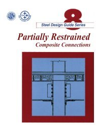
Steel <strong>Design</strong> <strong>Guide</strong> Series<br />
Stiffening of Wide-Flange Columns<br />
at Moment Connections:<br />
Wind and Seismic Applications<br />
Charles J. Carter, PE<br />
American Institute of Steel Construction, Inc.<br />
Chicago, IL<br />
AMERICAN INSTITUTE OF STEEL CONSTRUCTION, INC.
Copyright © 1999<br />
by<br />
American Institute of Steel Construction, Inc.<br />
All rights reserved. This book or any part thereof<br />
must not be reproduced in any form without the<br />
written permission of the publisher.<br />
The information presented in this publication has been prepared in accordance with recognized<br />
engineering principles and is for general information only. While it is believed<br />
to be accurate, this information should not be used or relied upon for any specific application<br />
without competent professional examination and verification of its accuracy,<br />
suitablility, and applicability by a licensed professional engineer, designer, or architect.<br />
The publication of the material contained herein is not intended as a representation<br />
or warranty on the part of the American Institute of Steel Construction or of any other<br />
person named herein, that this information is suitable for any general or particular use<br />
or of freedom from infringement of any patent or patents. Anyone making use of this<br />
information assumes all liability arising from such use.<br />
Caution must be exercised when relying upon other specifications and codes developed<br />
by other bodies and incorporated by reference herein since such material may be modified<br />
or amended from time to time subsequent to the printing of this edition. The<br />
Institute bears no responsibility for such material other than to refer to it and incorporate<br />
it by reference at the time of the initial publication of this edition.<br />
Printed in the United States of America<br />
Second Printing: October 2003<br />
© 2003 by American Institute of Steel Construction, Inc. All rights reserved.<br />
This publication or any part thereof must not be reproduced in any form without permission of the publisher.
TABLE OF CONTENTS<br />
1. Introduction ......................... 1 5.2 Column Stiffening for Weak-Axis Moment<br />
1.1 Scope............................ 1<br />
Connections ...................... 33<br />
1.2 Column Stiffening ................... 2 5.3 Column Stiffening for Concurrent Strong- and<br />
1.3 References Specifications .............. 2<br />
Weak-Axis Moment Connections ....... 34<br />
1.4 Definitions of Wind, Low-Seismic, and<br />
5.4 Web Doubler Plates as Reinforcement for<br />
High-Seismic Applications. ............ 2<br />
Local Web Yielding, Web Crippling, and/ or<br />
1.5 Acknowledgements. .................. 2<br />
Compression Buckling of the Web. ...... 35<br />
5.5 Web Doubler Plates at Locations of Weak-Axis<br />
2. Strong-Axis Moment Connections<br />
to Unreinforced Columns ...............<br />
2.1 Force Transfer in Unreinforced Columns ....<br />
3<br />
3<br />
Connections ......................<br />
5.6 Diagonal Stiffeners ..................<br />
35<br />
36<br />
2.2 Determining the <strong>Design</strong> Strength of an<br />
6. <strong>Design</strong> Examples ..................... 39<br />
Unreinforced Column ................ 5 Example 6-1. ......................... 39<br />
2.3 Column Cross-Sectional Stiffness<br />
Example 6-2. ......................... 40<br />
Considerations .................... 11 Example 6-3. ......................... 41<br />
2.4 <strong>Design</strong> Aids. ...................... 11 Example 6-4. ......................... 45<br />
Example 6-5. ......................... 47<br />
3. Economical Selection of Columns .........<br />
3.1 Achieving Balance Between Increases<br />
13 Example 6-6. .........................<br />
Example 6-7. .........................<br />
47<br />
50<br />
in Material Cost and Reductions in Example 6-8. ......................... 52<br />
LaborCost....................... 13 Example 6-9. ......................... 52<br />
3.2 Eliminating Column Stiffening. ......... 14 Example 6-10. ........................ 54<br />
3.3 Minimizing the Economic Impact of Column Example 6-11. ........................ 55<br />
Stiffening Requirements in Wind and Low- Example 6-12. ........................ 58<br />
Seismic Applications. ............... 15 Example 6-<strong>13.</strong> ........................ 59<br />
3.4 Minimizing the Economic Impact of Column Example 6-14. ........................ 61<br />
Stiffening Requirements in High-Seismic<br />
Applications. ..................... 16 APPENDIX A ......................... 67<br />
4. Strong-Axis Moment Connections APPENDIX B.......................... 75<br />
to Stiffened Columns ................. 17<br />
4.1 Determining the Column Stiffening APPENDIX C ......................... 83<br />
Requirements ..................... 18<br />
4.2 Force Transfer in Stiffened Columns ...... 20 APPENDIX D ......................... 95<br />
4.3 <strong>Design</strong> of Transverse Stiffeners ......... 22 Special Considerations. .................. 95<br />
4.4 <strong>Design</strong> of Web Doubler Plates .......... 27 Moment Connections to Column Webs. ....... 99<br />
5. Special Considerations ................. 33<br />
5.1 Column Stiffening for Beams of Differing<br />
Depth and/ or Top of Steel. ............ 33<br />
© 2003 by American Institute of Steel Construction, Inc. All rights reserved.<br />
This publication or any part thereof must not be reproduced in any form without permission of the publisher.
Chapter 1<br />
INTRODUCTION<br />
1.1 Scope<br />
The design of columns for axial load, concurrent axial load<br />
and flexure, and drift considerations is well established.<br />
However, the consideration of stiffening requirements for<br />
wide-flange columns at moment connections as a routine<br />
criterion in the selection of the components of the struc-<br />
tural frame is not as well established. Thus, the economic<br />
benefit of selecting columns with flange and web thick-<br />
nesses that do not require stiffening is not widely pur-<br />
sued, in spite of the efforts of other authors who<br />
have<br />
addressed this topic previously (Thornton, 1991; Thorn-<br />
ton, 1992; Barger, 1992; Dyker, 1992; and Ricker, 1992).<br />
This <strong>Design</strong> <strong>Guide</strong> is written with the intent of changing<br />
that trend and its contents are focused in two<br />
areas:<br />
1. The determination of design strength and stiffness<br />
for unreinforced wide-flange columns at locations<br />
of strong-axis beam-to-column moment connections;<br />
and,<br />
2. The design of column stiffening elements, such as<br />
transverse stiffeners (alsoknown as continuity plates)<br />
and web doubler plates, when the unreinforced col-<br />
umn strength and/ or stiffness is inadequate.<br />
Recommendations for economy are included in both cases.<br />
Force transfer and design strength of unreinforced<br />
columns with strong-axis moment connections are covered<br />
in Chapter 2. Economical considerations for unreinforced<br />
columns and columns with reinforcement are given in<br />
Chapter 3. Force transfer and design strength of reinforced<br />
columns with strong-axis moment connections, as well as<br />
the design of transverse stiffeners and web doubler plates,<br />
is covered in Chapter 4. Special considerations in column<br />
stiffening, such as stiffening for weak-axis moment con-<br />
nections and framing arrangements with offsets, are cov-<br />
ered in Chapter 5. <strong>Design</strong> examples that illustrate the<br />
application of these provisions are provided in Chapter 6,<br />
with design aids for wind and low-seismic applications in<br />
Appendices A, B, and C.<br />
1.2 Column Stiffening<br />
Transverse stiffeners are used to<br />
increase the strength<br />
and/ or stiffness of the column flange and/ or web at the lo-<br />
cation of a concentrated force, such as the flange force in-<br />
duced by the flange or flange-plate of a moment-connected<br />
beam. Web doubler plates are used to<br />
increase the shear<br />
strength and stiffness of the column panel-zone between<br />
the pair of flange forces from a moment-connected beam.<br />
The panel-zone is the area of the column that is bounded<br />
by the column flanges and the projections<br />
of the beam<br />
flanges as illustrated in Figure 1-1.<br />
If transverse stiffeners and/ or web doubler plates carry<br />
loads from members that frame to the weak-axis of the<br />
Projection of beam flanges, or<br />
transverse stiffeners, if present<br />
Column panel-zone<br />
Figure 1-1 Illustration of column panel-zone.<br />
1<br />
© 2003 by American Institute of Steel Construction, Inc. All rights reserved.<br />
This publication or any part thereof must not be reproduced in any form without permission of the publisher.
column, the recommendations herein must be adjusted as High-seismic applications are those for which inelastic bediscussed<br />
in Sections 5.2, 5.3, and 5.5. As discussed in havior is expected in the beams or panel-zones as a means<br />
Section 5.4, if web doubler plates are required to increase of dissipating the energy induced during strong ground<br />
the panel-zone shear strength, they can also be used to re- motions. Such buildings are designed to<br />
meet the requiresist<br />
local web yielding, web crippling, and/ or compression<br />
ments in both the LRFD Specification and the <strong>AISC</strong> Seisbuckling<br />
of the web per LRFD Specification Section K1. mic Provisions and a response modification factor R that<br />
As discussed in Section 5.6, diagonal stiffening can be is appropriate for the level of detailing required for the<br />
used in lieu of web doubler plates if it does not interfere moment-frame system selected is used in the determinawith<br />
the weak-axis framing. tion of seismic forces. 1<br />
Additionally, the moment con-<br />
nections used in high-seismic applications have special<br />
1.3 References Specifications<br />
This <strong>Design</strong> <strong>Guide</strong> is generally based upon the requirements<br />
seismic detailing that is appropriate for the moment-frame<br />
system selected.<br />
in the <strong>AISC</strong> LRFD Specification for Structural<br />
Steel Buildings (<strong>AISC</strong>, 1993), hereinafter referred to<br />
as 1.5 Acknowledgements<br />
the LRFD Specification, and the <strong>AISC</strong> Seismic Provisions This <strong>Design</strong> <strong>Guide</strong> resulted partially from work that was<br />
for Structural Steel Buildings (<strong>AISC</strong>, 1997a), hereinafter done as part of the <strong>Design</strong> Office Problems activity of<br />
referred to as the <strong>AISC</strong> Seismic Provisions. Although di- the ASCE Committee on <strong>Design</strong> of Steel Building Strucrect<br />
reference to the <strong>AISC</strong> Specification for Structural tures. Chapter 3 is based in large part upon this previous<br />
Steel Buildings—Allowable Stress <strong>Design</strong> and Plastic <strong>Design</strong><br />
(<strong>AISC</strong>, 1989) is not included, the principles herein Textbooks has enhanced this <strong>Design</strong> <strong>Guide</strong> through care-<br />
work. Additionally, the <strong>AISC</strong> Committee on Manuals and<br />
remain generally applicable.<br />
ful scrutiny, discussion, and suggestions for improvement.<br />
The author thanks the members of these <strong>AISC</strong> and ASCE<br />
1.4 Definitions of Wind, Low-Seismic, and High-<br />
Seismic Applications<br />
Committees for their invaluable input and guidance. In<br />
particular, Lawrence A. Kloiber, James O. Malley, and<br />
For the purposes of this <strong>Design</strong> <strong>Guide</strong>, wind, low-seismic<br />
David T. Ricker contributed significantly to the develop-<br />
and high-seismic applications are defined as follows.<br />
ment of Chapters 3 and 4 and William C. Minchin and<br />
Wind and low-seismic applications are those for which Thomas M. Murray provided helpful comments and sugthe<br />
structure is designed to<br />
meet the requirements in the gestions throughout the text of this <strong>Design</strong> <strong>Guide</strong>.<br />
LRFD Specification with no<br />
special seismic detailing.<br />
This includes all applications for which the structural response<br />
is intended toremain in the nominally elastic range 8, 6, and 4 are commonly used for Special Moment Frames (SMF), Inter-<br />
1From <strong>AISC</strong> Seismic Provisions Commentary Table I-C4-1, R-values of<br />
and the response modification factor<br />
R used in the determination<br />
mediate Moment Frames (IMF), and Ordinary Moment Frames (OMF),<br />
of seismic forces, if any, is not taken greater than 3.<br />
respectively.<br />
2<br />
© 2003 by American Institute of Steel Construction, Inc. All rights reserved.<br />
This publication or any part thereof must not be reproduced in any form without permission of the publisher.
Chapter 2<br />
STRONG-AXIS MOMENT CONNECTIONS<br />
TO UNREINFORCED COLUMNS<br />
In wind and low-seismic applications, it is often possible couple in the beam flanges or flange plates. The corre-<br />
to use wide-flange columns without transverse stiffeners sponding flange force Puf<br />
is calculated as:<br />
and web doubler plates at moment-connected beams. To<br />
use an unreinforced column, the following criteria must<br />
Mu<br />
Pu<br />
Puf<br />
<br />
be met:<br />
dm<br />
2<br />
(2.1-1)<br />
1. The required strength (Section 2.1) must be less than where<br />
or equal to the design strength (Section 2.2); and,<br />
Puf<br />
factored beam flange force, tensile or compres-<br />
2. The stiffness of the column cross-section must be adsive,<br />
kips<br />
equate to resist the bending deformations in the col-<br />
Mu<br />
factored beam end moment, kip-in.<br />
umn flange (Section 2.3).<br />
d o<br />
o<br />
2<br />
m m ment arm between the flange f rces, in.<br />
If these criteria cannot be met, column stiffening is required.<br />
Pu<br />
factored beam axial force, kips<br />
The formulation of Equation 2.1-1 is such that the com-<br />
In high-seismic applications, transverse stiffeners are bined effect of the moment and axial force is transmitted<br />
normally required, as discussed in Section 2.3. However, through the flange connections, ignoring any strength con-<br />
it remains possible in many cases to use wide-flange tribution from the web connection, which is usually more<br />
columns in high-seismic applications without web doubler<br />
flexible.<br />
plates at moment-connected beams.<br />
When the moment to be developed is less than the full<br />
flexural strength of the beam, as is commonly the case<br />
2.1 Force Transfer in Unreinforced Columns<br />
when a drift criterion governs the design, and the axial<br />
In an unreinforced column, concentrated forces from the force is relatively small, this calculation is fairly straightbeam<br />
flanges or flange plates are transferred locally into<br />
forward. However, when the full flexural strength of the<br />
the column flanges. These concentrated forces spread beam must be developed, or when the axial force is large,<br />
through the column flange and flange-to-web fillet region<br />
such a model seems toguarantee an overstress in the beam<br />
into<br />
the web as illustrated in Figure 2-1a. Shear is disconnection.<br />
Nonetheless, the above force transfer model<br />
illustrated in Figure 2-1b. Ultimately, axial forces in the remains acceptable because inelastic action intothe range<br />
flange, particularly for a directly welded flange moment<br />
persed between them in the column web (panel-zone) as<br />
column flanges balance this shear as illustrated in Figure of strain hardening allows the development<br />
of the design<br />
2-1c.<br />
flexural strength of the beam in the connection (Huang et<br />
al., 1973). Such self-limiting inelastic action is permitted<br />
2.1.1 Required Strength for Local Flange and Web Limit<br />
in LRFD Specification Section B9. Alternatively, a web<br />
States<br />
connection with a stiffness that is compatible with that of<br />
the connections of the beam flanges can be used toactivate<br />
In wind and low-seismic applications, beam end moments,<br />
the full beam cross-section and reduce the portion carried<br />
shears, and axial forces are determined by analysis for<br />
by the flanges.<br />
the loads and load combinations in LRFD Specification<br />
Note that, if a composite moment connection is used be-<br />
Section A4.1. Note that the total design moment is sel- tween the beam and column, the calculations in Equations<br />
dom equal to the flexural strength of the beam(s). A ra- 2.1-1and2.1-2mustbeadjustedbasedupontheappropriate<br />
tional approach such as that illustrated in Example 6-4 or<br />
similar to<br />
that proposed by Disque (1975) can be used in<br />
conjunction with these loads and load combinations. Different<br />
load combinations may be critical for different The actual moment arm can be readily calculated as the distance be-<br />
2<br />
tween the centers of the flanges or flange plates as illustrated in Figure<br />
local-strength limit states.<br />
2-1a. Alternatively, as stated in LRFD Specification Commentary Section<br />
K1.7, 0.95 times the beam depth has been conservatively used for<br />
at the column face into an effective tension-compression<br />
d in the<br />
For the general case, the beam end moment is resolved<br />
past.<br />
m<br />
3<br />
© 2003 by American Institute of Steel Construction, Inc. All rights reserved.<br />
This publication or any part thereof must not be reproduced in any form without permission of the publisher.
dm<br />
(a) Beam flange forces<br />
distributed through<br />
column flange and fillet<br />
(b) Free-body diagram<br />
illustrating shear and<br />
axial force transfer<br />
through column panelzone<br />
Note: beam shear and axial force (if any) omitted for clarity.<br />
(c) Free-body diagram<br />
illustrating resulting<br />
column axial forces and<br />
flange forces (moments)<br />
Figure 2-1 Force transfer in unreinforced columns.<br />
detailing and force transfer model. Some possible compos-<br />
Figure C-11.1 can be used. From <strong>AISC</strong> Seismic Provi-<br />
ite connections are illustrated in <strong>AISC</strong> (1997a), Leon et al. sions Section 11.2a, the flange forces in Ordinary Moment<br />
(1996), and Viest et al. (1998). Frames (OMF) need not be taken greater than those that<br />
In high-seismic applications, the moments, shears, and correspond to a moment M u equal to 1. 1RyFyZx<br />
or the<br />
axial forces are determined by analysis for the loads and maximum moment that can be delivered by the system,<br />
load combinations in LRFD Specification Section A4.1 whichever is less.<br />
and <strong>AISC</strong> Seismic Provisions Section 4.1. The resulting For Special Moment Frames (SMF) and Intermediate<br />
flange force Puf<br />
is then determined using Equation 2.1-1. Moment Frames (IMF), a cyclic inelastic rotation capa-<br />
Note that the corresponding connection details have spe- bility of 3 and 2 percent, respectively, is required. Several<br />
cial seismic detailing to provide for controlled inelastic alternative connection details using reinforcement, such as<br />
deformations during strong ground motion as a means of coverplates, ribs, or haunches, or using reduced beam secdissipating<br />
the input energy from an earthquake.<br />
3<br />
For Ordinary Moment Frames (OMF), a cyclic inelastions<br />
(dogbones), have been successfully tested and used.<br />
Such connections shift the location of the plastic hinge<br />
tic rotation capability of 1 percent is required. Moment into the beam by a distance a from the column face as<br />
connections such as those discussed in <strong>AISC</strong> Seismic illustrated in Figure 2-2. From <strong>AISC</strong> Seismic Provisions<br />
Provisions Commentary Section C11.2 and illustrated in Section 9.3a, the flange forces in Special Moment Frames<br />
3<br />
(SMF) and Intermediate Moment Frames (IMF) need not<br />
With strong panel-zones and fully restrained (FR) construction, the primary<br />
source of inelasticity is commonly hinging in the beam itself. If the be taken greater than:<br />
panel-zone is a significant source of inelasticity, or if partially restrained<br />
(PR) construction is used, the flange-force calculation in Equation 2.1-2<br />
Mu<br />
11 . RyFyZ<br />
Vua<br />
Puf<br />
<br />
should be adjusted based upon the actual force transfer model.<br />
d<br />
d<br />
(2.1-2)<br />
4<br />
m<br />
m<br />
© 2003 by American Institute of Steel Construction, Inc. All rights reserved.<br />
This publication or any part thereof must not be reproduced in any form without permission of the publisher.
2.2 Determining the <strong>Design</strong> Strength of an<br />
Unreinforced Column<br />
An unreinforced column must have sufficient strength lo-<br />
cally in the flange(s) and web to<br />
resist the resulting flange-<br />
force couple(s). Moment connections are termed “double<br />
concentrated forces” in LRFD Specification Section K1<br />
because there is one tensile flange force and one compres-<br />
sive flange force acting on the same side of the column<br />
as illustrated in Figure 2-4a. When opposing moment-<br />
where 1.1 is an adjustment factor that nominally accounts<br />
Seismic Provisions Load Combinations 4-1 and 4-2 and<br />
for the effects of strain hardening, and<br />
Equation 2.1-1, the total panel-zone shear force is calculated<br />
with Equation 2.1-3. As a worst case, however, the<br />
Ry<br />
an adjustment factor that nominally accounts for<br />
total panel-zone shear force<br />
Vu<br />
need not be taken greater<br />
material yield overstrength per <strong>AISC</strong> Seismic<br />
than:<br />
Provisions Section 6.2<br />
1.5 for ASTM A36 wide-flange beams V u 0. 8[( Puf) 1( Puf) 2] Vus<br />
(2.1-4)<br />
1.3 for ASTM A572 grade 42 wide-flange beams<br />
1.1 for wide-flange beams in other material The factor 0.8 in Equation 2.1-4 is from <strong>AISC</strong> Seismic<br />
grades (e.g., ASTM A992 or A572 grade 50) Provisions Section 9.3a. It recognizes that the effect of<br />
Fy<br />
beam specified minimum yield strength, ksi the gravity loads will counteract some portion of the effect<br />
Z plastic section modulus of beam cross-section at of the lateral loads on one side of an interior column and<br />
hinge location (distance a from column face), in.<br />
3 thereby inhibit the development of the full plastic moment<br />
Vu<br />
shear in beam at hinge location (distance a from<br />
in the beam on that side.<br />
column face), kips<br />
In wind, low-seismic, and high-seismic applications, for<br />
a distance from face of column flange to<br />
plastic a column with only one moment-connected beam, Equa-<br />
hinge location, in.<br />
tion 2.1-3 can be reduced t o:<br />
The axial force effect is neglected in Equation 2.1-2, since<br />
Vu<br />
Puf<br />
Vus<br />
(2.1-5)<br />
the model is already based conservatively upon the fully<br />
yielded and strain-hardened beam flange at the critical Note that gravity-load reduction, as used for high-seismic<br />
section.<br />
applications in Equation 2.1-4, is not appropriate in Equa-<br />
tion 2.1-5 for a column with only one moment-connected<br />
2.1.2 Required Strength for Panel-Zone Shear<br />
beam.<br />
As illustrated in Figure 2-3, the total panel-zone shear<br />
force<br />
Vu<br />
at an interior column results from the combined<br />
effects of two moment-connected beams and the story<br />
shear Vus. In wind and low-seismic applications, the to-<br />
tal panel-zone shear force<br />
V is calculated as:<br />
V ( P ) ( P ) V (2.1-3)<br />
u<br />
u<br />
uf 1 uf 2<br />
In high-seismic applications, when the flange forces have<br />
been calculated using the moment resulting from <strong>AISC</strong><br />
us<br />
Reinforced zone or zone between<br />
beam end connection and reduced<br />
beam section (RBS)<br />
a<br />
Plastic hinge location<br />
Figure 2-2 Schematic illustration of moment connection<br />
for high-seismic applications.<br />
5<br />
© 2003 by American Institute of Steel Construction, Inc. All rights reserved.<br />
This publication or any part thereof must not be reproduced in any form without permission of the publisher.
connected beams coincide, a pair of double concentrated<br />
Pu<br />
Fr o P u 04 . Py, R v 09 . 06 . Fydct w 14 . <br />
forces results as illustrated in Figures 2-4b (the gravity<br />
Py<br />
load case) and 2-4c (the lateral load case).<br />
The design strength of the panel-zone in shear must be<br />
(2.2-2)<br />
checked for all columns with moment connected beams.<br />
In the second assumption, it is recognized that signif-<br />
For a tensile flange force, the design strength of the flange<br />
icant post-yield panel-zone strength is ignored by limitin<br />
local flange bending and the design strength of the web<br />
ing the calculated panel-zone shear strength to<br />
that in the<br />
in local yielding must also be checked. For a compres-<br />
nominally elastic range. At the same time, it must be realsive<br />
flange force, the design strength of the web in lo-<br />
ized that inelastic deformations of the panel-zone can sigcal<br />
yielding, crippling, and compression buckling must be<br />
nificantly impact the strength and stability of the frame.<br />
checked. Note that the compression buckling limit state<br />
Accordingly, a higher strength can generally be utilized<br />
is applicable only when the compressive components of a<br />
as long as the effect of inelastic panel-zone deformation<br />
pair of double concentrated forces coincide as illustrated in<br />
on frame stability is considered in the analysis. When this<br />
Figure 2-4b (i.e., at the bottom flanges). If the magnitudes<br />
option is selected, the resulting design strength given in<br />
of these opposing flange forces are not equal, the compres-<br />
Equations 2.2-3 and 2.2-4 is determined from LRFD Specsion<br />
buckling limit state is checked for the smaller flange<br />
ification Equations K1-11 and K1-12 with consideration of<br />
force, since only this portion of the larger flange force must<br />
the magnitude of the axial load<br />
Pu<br />
in the column:<br />
be resisted. Each of these limit states is discussed below.<br />
Fr o P u 075 . Py,<br />
2.2.1 Panel-Zone Shear Strength<br />
3b t2<br />
f f<br />
In wind and low-seismic applications and high-seismic R v 0. 9 0. 6Fydctw<br />
1 <br />
ddt<br />
applications involving Ordinary Moment Frames (OMF),<br />
b cw<br />
(2.2-3)<br />
(P uf ) 1 (P uf ) 1<br />
the design shear strength of the panel-zone Rv<br />
is determined<br />
with the provisions of LRFD Specification Section<br />
Fr o P u 075 . Py,<br />
K1.7, which allows two alternative assumptions.<br />
b t<br />
2<br />
The first assumption is that, for calculation purposes,<br />
3 f f 12 . Pu<br />
R v 09 . 06 . Fydct w 1<br />
19 . <br />
the behavior<br />
of the panel-zone remains nominally within<br />
ddt b cw Py<br />
<br />
the elastic range. The resulting design strength given in<br />
Equations 2.2-1 and 2.2-2 is then determined from LRFD (2.2-4)<br />
Specification Equations K1-9 or K1-10 with consideration<br />
of the magnitude of the axial load<br />
Pu<br />
in the column:<br />
For Fy<br />
equal to or less than 50 ksi, all W-shapes listed<br />
in ASTM A6 except a W30 90 and a W16 31 have<br />
For P u 0. 4 Py, R v 0. 9 0. 6 Fydctw<br />
(2.2-1) a web thickness that is adequate to<br />
prevent buckling<br />
(M u ) 2 (M u ) 1<br />
V us<br />
(P uf ) 1<br />
(P uf ) 1<br />
V u<br />
<br />
<br />
V us<br />
Note: shear forces in beams and moments and axial forces in column omitted for clarity.<br />
Figure 2-3 Panel-zone web shear at an interior column (with<br />
moment-connected beams bending in reverse curvature).<br />
6<br />
© 2003 by American Institute of Steel Construction, Inc. All rights reserved.<br />
This publication or any part thereof must not be reproduced in any form without permission of the publisher.
±Puf<br />
±(Puf)2<br />
±(Puf)1 ±(Puf)2<br />
±(Puf)1<br />
±Puf<br />
±(Puf)2<br />
±(Puf)1 ±(Puf)2<br />
±(Puf)1<br />
(a) Double concentrated forces (b) A pair of double concentrated forces,<br />
gravity load case<br />
(c) A pair of double concentrated forces,<br />
lateral load case<br />
Figure 2-4 Moment connection flange force terminology.<br />
© 2003 by American Institute of Steel Construction, Inc. All rights reserved.<br />
This publication or any part thereof must not be reproduced in any form without permission of the publisher.<br />
7
under panel-zone web shear per LRFD Specification Sec- Note that Equation 2.2-7 is in a form that has been adapted<br />
tion F2. For Fy<br />
50 ksi, these two shapes exceed the from that which appears in the <strong>AISC</strong> Seismic Provisions.<br />
limit on ht / w by 1.9 and 1.5 percent, respectively. Thus,<br />
for all practical purposes, in wind and low-seismic applications,<br />
shear buckling of the column web need not be<br />
2.2.2 Local Flange Bending<br />
F<br />
4 When a directly welded flange or flange-plated moment<br />
checked for columns with y equal to or less than 50 ksi.<br />
connection is used, differential stiffness across the width<br />
In high-seismic applications involving Special Moment<br />
of an unstiffened column flange results in a stress concen-<br />
Frames (SMF) or Intermediate Moment Frames (IMF), the<br />
tration in the weld adjacent to the column web as illuseffect<br />
of inelastic panel-zone deformation on frame stabiltrated<br />
in Figure 2-5 that must be limited for tensile flange<br />
ity must be considered in the analysis. The design shear<br />
forces. The design local flange bending strength Rn<br />
strength of the panel-zone Rv<br />
given in Equations 2.2-5<br />
given in Equation 2.2-8 is determined from LRFD Speciand<br />
2.2-6 is determined from <strong>AISC</strong> Seismic Provisions<br />
fication Equation K1.1 with consideration of the proximity<br />
Section 9.3a:<br />
of the concentrated flange force to the end of the column:<br />
Fr o P u 075 . Py,<br />
2<br />
R n 0. 9 6. 25 tf<br />
Fy Ct<br />
(2.2-8)<br />
3b t2<br />
f f<br />
R v 0. 75 0. 6Fydctw<br />
1 (2.2-5) When an extended end-plate moment connection is used,<br />
ddt b cw<br />
flange bending must be limited to<br />
prevent yielding of the<br />
column flange under tensile flange forces. The design local<br />
Fr o P u 075 . Py,<br />
flange bending strength Rn<br />
given in Equation 2.2-9 is<br />
b t<br />
2<br />
determined from Murray (1990) with consideration of the<br />
3 f f 12 . Pu<br />
R v 075 . 06 . Fydct w 1<br />
19 . <br />
proximity of the concentrated flange force tothe end of the<br />
ddt b cw Py<br />
column as:<br />
(2.2-6)<br />
bs<br />
2<br />
R n 0. 9 <br />
t F C<br />
p f y t (2.2-9)<br />
These provisions are identical to those in LRFD Specification<br />
Equations K1-11 and K1-12, except that a lower re-<br />
m e<br />
sistance factor is used to provide an added margin against<br />
where<br />
excessive panel-zone yielding. Additionally, to prevent t f column flange thickness, in.<br />
shear buckling under the higher inelastic demand associ-<br />
Fy<br />
column specified minimum yield strength, ksi.<br />
ated with high-seismic loading, the minimum thickness of<br />
Note that Equation 2.2-9 was developed from rethe<br />
unreinforced column web given in Equation 2.2-7 is<br />
search that considered only ASTM A36 material<br />
determined from <strong>AISC</strong> Seismic Provisions Section 9.3b:<br />
(Curtis and Murray, 1989). If column material<br />
d d t<br />
with higher yield strength is used, it is recom-<br />
m c 2 f<br />
tw<br />
min <br />
(2.2-7)<br />
mended that Fy<br />
be taken conservatively as 36 ksi<br />
90<br />
in Equation 2.2-9.<br />
where<br />
tw<br />
column web thickness, in.<br />
b f column flange width, in.<br />
t f column flange thickness, in.<br />
db<br />
beam depth, in.<br />
dc<br />
column depth, in.<br />
Fy<br />
column minimum specified yield strength, ksi<br />
Pu<br />
column required axial strength, in.<br />
Py<br />
FyA, column axial yield strength, in.<br />
A column cross-sectional area, in.<br />
2<br />
dm<br />
moment arm between concentrated flange forces,<br />
in.<br />
4If using allowable stress design, the shear buckling limit is slightly<br />
more conservative and the following W-shapes must be checked<br />
for shear buckling: W44230, W40215, W40199, W40183,<br />
W40174, W40167, W40149, W36150, W36135, W33130,<br />
W33118, W3099, W3090, W2784, W2468, W2455,<br />
W2144, W1835, W1631, W1626, W1422, and W1214.<br />
Figure 2-5 Concentration<br />
of stress in flange or<br />
flange-plate weld for a<br />
column with thin flanges<br />
and no transverse<br />
stiffeners.<br />
8<br />
© 2003 by American Institute of Steel Construction, Inc. All rights reserved.<br />
This publication or any part thereof must not be reproduced in any form without permission of the publisher.
Ct<br />
0.5 if the distance from the column end to the<br />
closer face of the beam tension flange is less than<br />
When an extended end-plate moment connection is used,<br />
the concentrated force is distributed to the column web as<br />
10t<br />
f<br />
illustrated in Figure 2-7b. The design local web yielding<br />
1 otherwise<br />
strength Rn<br />
given in Equation 2.2-11 is determined from<br />
b s 2. 5(2 pftfb), in., for a four-bolt unstiffened exconcentrated<br />
Murray (1990) with consideration of the proximity of the<br />
tended end plate; see Figure 2-6a<br />
flange force to the end of the column:<br />
2pft fb3. 5 pb, in., for an eight-bolt stiffened<br />
extended end plate; see Figure 2-6b<br />
R n 1. 0 [ Ct(6k2 tp) N] Fytw<br />
(2.2-11)<br />
p f distance from centerline of bolt tonearer surface<br />
o o<br />
d 1<br />
where<br />
f the tensi n flange, in; b plus / 2 in. is genercolumn<br />
web thickness, in.<br />
ally enough toprovide wrench clearance; 2 in. is tw<br />
<br />
a common fabricator standard<br />
Fy<br />
column specified minimum yield strength, ksi<br />
t fb beam flange thickness, in.<br />
k distance from outside face of column flange tothe<br />
pb<br />
vertical pitch of bolt group above and bolt group<br />
web toe of the flange-to-web fillet, in.<br />
below tension flange, in.<br />
N beam flange or flange plate thickness plus 2 w, in.<br />
1/4<br />
pe<br />
Ct<br />
0.5 if the distance from the column end to<br />
the<br />
m 1. 36d<br />
<br />
for a four-bolt unstiffened extended closer face of the beam flange is less than dc<br />
b<br />
end plate<br />
1 otherwise<br />
1/4<br />
w leg size of fillet weld or groove weld reinforce-<br />
ment, if used, in.<br />
pe<br />
1.<br />
13d<br />
<br />
for an eight-bolt stiffened extended<br />
b<br />
tp<br />
end-plate thickness, in.<br />
end plate<br />
dc<br />
column depth, in.<br />
g db<br />
pe<br />
k1<br />
2 4<br />
g bolt gage, in.<br />
2.2.4 Web Crippling<br />
db<br />
bolt diameter, in. The design local web crippling strength Rn<br />
given in<br />
k1<br />
distance from beam web centerline to flange toe<br />
Equation 2.2-12 is determined from LRFD Specification<br />
of flange-to-web fillet, in. Equations K1-4, K1-5, or K1-6 with consideration of the<br />
proximity of the concentrated flange force tothe end of the<br />
2.2.3 Local Web Yielding<br />
column:<br />
When a directly welded flange or flange-plated moment<br />
15 .<br />
connection is used, the concentrated force is distributed 2 tw<br />
Ft y f<br />
R n 0. 75 135Cttw<br />
1 Nd<br />
to<br />
the column web as illustrated in Figure 2-7a. The design<br />
t <br />
f t w<br />
local web yielding strength Rn<br />
given in Equation<br />
2.2-10 is determined from LRFD Specification Equations<br />
(2.2-12)<br />
K1-2 or K1-3 with consideration of the proximity of the<br />
concentrated flange force to the end of the column:<br />
where<br />
Ct<br />
0.5 if the distance from the column end to<br />
the<br />
R n 1. 0 [ Ct(5 k) N] Fytw<br />
(2.2-10)<br />
closer face of the beam compression flange is less<br />
than dc/2<br />
1 otherwise<br />
tw<br />
column web thickness, in.<br />
Nd<br />
3 N/ dc<br />
if the distance from the column end to<br />
the<br />
closer face of the beam tension flange is either:<br />
(1) greater than or equal t o dc/2; or, (2) less than<br />
dc/2 and N/ dc<br />
is less than or equal to<br />
0.2.<br />
4N<br />
<br />
<br />
0.<br />
2<br />
d otherwise<br />
c<br />
t f<br />
Fy<br />
column flange thickness, in.<br />
column specified minimum yield strength, ksi<br />
(a) Four-bolt unstiffened (b) Eight-bolt stiffened<br />
N beam flange or flange plate thickness plus 2wfor<br />
directly welded flange or flange-plated moment<br />
connection, in.<br />
Figure 2-6 Configuration of extended end-plate moment<br />
beam flange thickness plus (2w2 tp) for extended<br />
connections.<br />
end-plate moment connections, in.<br />
9<br />
© 2003 by American Institute of Steel Construction, Inc. All rights reserved.<br />
This publication or any part thereof must not be reproduced in any form without permission of the publisher.
w leg size of fillet weld or groove weld reinforce- web compression buckling strength Rn<br />
given in Equament,<br />
if used, in.<br />
tion 2.2-13 is determined from LRFD Specification Equations<br />
K1-8 with consideration of the proximity of the<br />
tp<br />
end-plate thickness, in.<br />
d column depth, in.<br />
concentrated flange force to the end of the column:<br />
c<br />
Note that, from LRFD Specification Commentary Sec-<br />
4, 100C t Fy<br />
R . <br />
tion K1.4, for the rolled shapes listed in ASTM A6, the<br />
n 0 90 (2.2-13)<br />
h<br />
limit state of web crippling will not govern the design of<br />
where<br />
transverse stiffening for a moment connection, except toa<br />
W1250 or W1033 column. That is, if transverse stiffcloser<br />
face of the compression flanges is less than<br />
Ct<br />
0.5 if the distance from the column end to<br />
the<br />
ening is required, another limit state, such as local web<br />
yielding or local flange bending, will be more critical in<br />
dc/2<br />
all except the aforementioned two<br />
cases.<br />
1 otherwise<br />
tw<br />
column web thickness, in.<br />
Fy<br />
column specified minimum yield strength, ksi<br />
2.2.5 Compression Buckling of the Web<br />
h dc<br />
2 k, in.<br />
When a pair of compressive flange forces coincide as il- dc<br />
column depth, in.<br />
lustrated in Figure 2-4b, the column web is subject to out- k distance from outside face of column flange tothe<br />
of-plane buckling as illustrated in Figure 2-8. The design<br />
web toe of the flange-to-web fillet, in.<br />
3<br />
t w<br />
k<br />
k<br />
t p<br />
1:1 slope<br />
5k + N<br />
N<br />
±P uf<br />
6k + N + 2tp<br />
N<br />
±P uf<br />
±F y<br />
2.5<br />
1<br />
3<br />
±F y<br />
1<br />
(a) Directly welded flange or flangeplated<br />
moment connection<br />
(b) Extended end-plate moment<br />
connection<br />
Figure 2-7 Local force transfer for local web yielding limit state.<br />
Zone of column web subject to<br />
compression buckling (out-of-plane)<br />
(P uf ) 2<br />
h k(P uf ) 1<br />
k<br />
Figure 2-8 Compression buckling of the column web.<br />
10<br />
© 2003 by American Institute of Steel Construction, Inc. All rights reserved.<br />
This publication or any part thereof must not be reproduced in any form without permission of the publisher.
2.3 Column Cross-Sectional Stiffness Considerations<br />
In addition to<br />
satisfying the strength requirements given<br />
if testing demonstrates that the intended inelastic rotation<br />
can be achieved without their use.<br />
in Section 2.2, the supporting column must also<br />
have sufficient<br />
stiffness to resist local deformations of the cross-<br />
2.4 <strong>Design</strong> Aids<br />
section under the tensile and compressive flange forces. In For wind and low-seismic applications, the determination<br />
wind and low-seismic applications, design for the strength of the design strength of unreinforced wide-flange shapes<br />
criteria in Section 2.2 has historically resulted in columns<br />
used as columns is simplified with the tables in Appenwith<br />
suitable stiffness as well as strength. In high-seismic dices A, B, and C. In Appendix A, the design column<br />
applications, however, the associated higher inelastic de- panel-zone shear strength is tabulated. In Appendix B, the<br />
mand necessitates a more explicit consideration of flange design local column strength at locations of concentrated<br />
stiffness to limit the variation in stress distribution across<br />
flange forces is tabulated assuming that the concentrated<br />
the width of the connected flange or flange plate. <strong>AISC</strong> force is not at a column-end location. In Appendix C, the<br />
Seismic Provisions Sections 9.5 and 11.3 indicate that design local column strength at locations of concentrated<br />
transverse stiffeners that match the configuration of those<br />
flange forces is tabulated assuming that the concentrated<br />
used in the qualifying cyclic tests (see <strong>AISC</strong> Seismic Pro-<br />
force is at a column-end location. The use of these tables<br />
visions Appendix S) for the moment connection tobe used is illustrated in several of the example problems in Chapare<br />
required. Note that transverse stiffeners are not required ter 6.<br />
11<br />
© 2003 by American Institute of Steel Construction, Inc. All rights reserved.<br />
This publication or any part thereof must not be reproduced in any form without permission of the publisher.
© 2003 by American Institute of Steel Construction, Inc. All rights reserved.<br />
This publication or any part thereof must not be reproduced in any form without permission of the publisher.
Chapter 3<br />
ECONOMICAL SELECTION OF COLUMNS<br />
Transverse stiffeners and web doubler plates are ex- welding transverse stiffeners and web doubler plates that<br />
tremely labor-intensive detail materials due primarily to is predominant in their cost.<br />
the fit-up and welding that is associated with their use. An equivalent column weight change is tabulated from<br />
Additionally, issues such as restraint, lamellar tearing and these estimated costs based upon a mill price of $425 per<br />
welding sequence must be addressed when transverse ton, which is a median value in the common range of<br />
stiffeners and/ or web doubler plates are used. As such, from $400 t o $450 per ton FOB,<br />
67 ,<br />
and a 14-ft floor-to-<br />
they add considerable cost in spite of their disproportion- floor height. The tabulated values are calculated as the esately<br />
low material cost. If transverse stiffeners and web timated cost times 2000 lb per ton divided by $425 per ton<br />
doubler plates can be eliminated and an unreinforced col-<br />
divided by the 14-ft length. The resulting value is the esumn<br />
can be used, significant cost savings can often be re- timated maximum per-foot column-weight increase that<br />
alized. Additionally, the elimination of column stiffening could be made to eliminate that element of the column<br />
will simplify (and thereby economize) connections that stiffening without increasing cost. In fact, because the tabare<br />
made to the weak axis of the column. ulated values do not consider other intangible economic<br />
In wind and low-seismic applications, the specification<br />
benefits, such as the simplification of connections that are<br />
of column sizes that eliminate transverse stiffeners is en- made to the weak axis of the column, the tabulated value<br />
couraged. In high-seismic applications, however, trans- should be considered conservative.<br />
verse stiffeners will normally be required, as discussed As an example, consider a W1490 column with fullpreviously<br />
in Section 2.3.<br />
depth transverse stiffeners (Case 5, Table 3.1) at each<br />
In wind, low-seismic, and high-seismic applications, beam flange (2 pairs total) and one web doubler plate<br />
the specification of column sizes that eliminate web dou- (Case 8, Table 3.1). The total of the tabulated column-<br />
bler plates is encouraged. Web doubler plates require weight-change values for this column stiffening arrangesignificant<br />
welding intothe column flange-to-web fillet region<br />
(k-area), which is an area of potentially lower notch ment is 40 lb/ft 82 lb/ft 122 lb/ft. Thus, if any<br />
heavier W14 up to and including a W14211 column<br />
toughness (<strong>AISC</strong>, 1997b). The shrinkage that accompa- could be used without transverse stiffeners and a web dou-<br />
nies the cooling of these welds typically can distort the bler plate, it would likely be more economical than the<br />
cross-section and overwelding in this region carries the W1490. In most cases, the actual increase in column<br />
potential for cracking. Additionally, the weld joint may re- weight required to eliminate column stiffening will be<br />
quire the use of a non-prequalified detail as discussed in much less than the maximum calculated and a significant<br />
Section 4.4.3.<br />
economic benefit can be realized.<br />
When the required column-weight change exceeds the<br />
3.1 Achieving Balance Between Increases in Material<br />
Cost and Reductions in Labor Cost<br />
sum of the tabulated values, some engineering judgment<br />
must be used. If the comparison is unfavorable, but still<br />
In Table 3.1, estimated costs are given for some arbitrarily close, the use of a heavier column might still be justiselected<br />
transverse stiffener and web doubler plate details fied by the aforementioned intangibles. Alternatively, the<br />
as illustrated in Figure 3-1. These estimated costs were designer may still find it advantageous to<br />
investigate the<br />
determined by averaging the cost estimates5<br />
provided by possibility of eliminating the web doubler plate only ( or<br />
several fabricators and rounding the result to<br />
the near- transverse stiffeners only in some cases).<br />
est five-dollar increment. When comparing these typical As an example, consider again the W1490 column<br />
details toactual details, it should be noted that the compar-<br />
at each beam flange (two pairs total) and one web dou-<br />
than the thicknesses or overall dimensions of the plate ma-<br />
bler plate (Case 8, Table 3.1). If any heavier W14 up to<br />
with full-depth transverse stiffeners (Case 5, Table 3.1)<br />
ative weld types and sizes are of much greater significance<br />
terials. It is the labor involved in cutting, profiling, and<br />
6FOB stands for “free on board,” which indicates that the quoted price<br />
5<br />
assumes delivery to the indicated location. In the above case, the indi-<br />
The estimated costs are predicated upon the material and labor costs<br />
cated location is the mill itself; subsequent shipping would incur addithat<br />
existed at the time this <strong>Design</strong> <strong>Guide</strong> was written (circa early 1999).<br />
tional cost.<br />
Because it is anticipated that labor costs will continue to<br />
rise at a faster<br />
rate than material costs, the user may find it advantageous toperiodically<br />
7Because mill prices fluctuate, the designer may find it advantageous to<br />
inquire with local fabricators to determine a more current estimate of periodically inquire with fabricators, steel mills, or other shape suppliers<br />
these costs.<br />
to determine the current range of mill prices.<br />
13<br />
© 2003 by American Institute of Steel Construction, Inc. All rights reserved.<br />
This publication or any part thereof must not be reproduced in any form without permission of the publisher.
and including a W14159 column could be used with- the design strength of the column, yet there will be<br />
out a web doubler plate, but with the transverse stiff- little or no impact on the material cost. Mill grade<br />
eners, it would be more economical than the W1490. extras for 50-ksi wide-flange material are largely<br />
Similarly, if any heavier W14 up to<br />
and including a nonexistent in shapes that weigh as much as 150 lb<br />
W14120 column could be used without transverse stiff- per ft of length.<br />
8<br />
Even for W-shapes in weight ranges<br />
eners, but with a web doubler plate, it would be more eco-<br />
that have grade extras, these nominal cost differences<br />
nomical than the W1490. of twoor three pennies per pound are negligible when<br />
compared to<br />
the advantage gained in detail material<br />
savings. Column material with even higher yield<br />
3.2 Eliminating Column Stiffening<br />
strength, such as ASTM A913 grade 65 material, is<br />
From Section 3.1, it is clear that there is significant poten-<br />
also available; however, the associated material cost<br />
tial for economic benefit when transverse stiffeners and<br />
differential is greater.<br />
web doubler plates can be eliminated. Therefore, the de-<br />
2. Consider a different column section that has a<br />
signer should consider alternatives that eliminate the need<br />
thicker flange and/ or web, as appropriate. This infor<br />
column stiffening, when possible. The design aids in<br />
crease in material cost, given today’s typical FOB<br />
Appendices A, B, and C provide for the rapid identifimill<br />
price for common grades9<br />
of steel of approx-<br />
cation<br />
of column strength and stiffening requirements in<br />
imately $400 t o $450 per ton, is in most cases<br />
wind and low-seismic applications. Some additional suggestions<br />
follow.<br />
8Inquire with steel mills to determine the current range of shapes for<br />
1. Specify column material with yield strength of 50 which a grade extra applies.<br />
ksi, such as ASTM A992 or A572 grade 50 steel.<br />
9Common grades include ASTM A992, ASTM A572 grade 50, and<br />
The increased minimum yield strength will increase A36.<br />
Table 3.1<br />
Estimated Cost of Various Column Stiffening Details (as illustrated in Figure 3-1)<br />
Equivalent<br />
Column Weight<br />
(lb/ft) if Wide-<br />
Flange Steel Costs<br />
Attachment to Attachment to Estimated $425 per Ton from<br />
Case Thickness Column Flange Column Web Cost<br />
3<br />
Rolling Mill<br />
Partial-Depth Transverse Stiffeners (Two Pairs)<br />
1 3 3<br />
4 PL 4 / 0’-10 (ASTM A36) with one / / corner clip each<br />
2 4 4<br />
1<br />
1/ 2 in. fitted to bear<br />
3/ 16-in. fillet welds $80 27<br />
2 1 in. fitted to bear<br />
5/ 16 -in. fillet welds $120 40<br />
3<br />
1/ 2 in.<br />
1/ 4-in. fillet welds<br />
3/ 16-in. fillet welds $90 30<br />
4 1 in.<br />
1 1<br />
/ -in. fillet welds<br />
5/ -in. fillet welds $140 47<br />
2 16<br />
Full-Depth Transverse Stiffeners (Two Pairs)<br />
1 9 3 3<br />
4 PL 4 / 1’-0 / (ASTM A36) with two / / corner clips each<br />
2 16 4 4<br />
5<br />
1/ 2 in.<br />
1/ 4-in. fillet welds<br />
3/ 16-in. fillet welds $120 40<br />
6 1 in.<br />
1/ 2-in. fillet welds<br />
5/ 16-in. fillet welds $210 71<br />
7<br />
1<br />
1 / in. CJP groove weld<br />
1<br />
1<br />
/ -in. fillet welds $470 158<br />
2 2<br />
Web Doubler Plate (One)<br />
1 PL 12 / 2’-0 (ASTM A36)<br />
5 8<br />
8<br />
1/ 2 in. CJP groove weld<br />
3/ 16-in. fillet welds $245 82<br />
9<br />
3/ 4 in. CJP groove weld<br />
5/ 16-in. fillet welds $370 124<br />
10<br />
3/ 4 in.<br />
5 2<br />
/ 8-in. fillet weld<br />
5/ 16-in. fillet welds $215 72<br />
11 1 in.<br />
7 2<br />
/ -in. fillet weld<br />
5/ -in. fillet welds $305 103<br />
8 16<br />
1The consulted fabricators were asked if they would instead prefer a CJP-groove-welded detail in place of this<br />
larger-size fillet-welded detail. In all cases, the answer was no.<br />
2A 3/ -in. by 3<br />
4 / 4-in. bevel on the column-flange edges of the web doubler plate is used to clear the column<br />
flange-to-web fillet. It should be noted that the fillet-welded web doubler plate detail in Case 10 is not suitable<br />
for high seismic applications because the weld size does not develop the strength of the full thickness of the<br />
web doubler plate.<br />
3A floor-to-floor height of 14 ft has been used in this tabulation.<br />
14<br />
© 2003 by American Institute of Steel Construction, Inc. All rights reserved.<br />
This publication or any part thereof must not be reproduced in any form without permission of the publisher.
easily offset by the savings in labor costs, as illus- in wind and low-seismic applications:<br />
trated previously in Section 3.1.<br />
1. Where allowed by governing building codes, de-<br />
3. Consider a deeper cross-section for the beam that<br />
sign column stiffening in response to<br />
the actual<br />
is connected to the column. Increasing the depth of<br />
moments and resulting flange forces rather than<br />
the beam decreases the flange force delivered due to<br />
the full flexural strength of the cross-section; the<br />
the increase in moment arm between the flange-force<br />
latter simply wastes money in the majority<br />
of<br />
couple. If it were possible toreplace a W1650 with<br />
cases. When the Engineer of Record (EOR) dela<br />
W1850, the material cost would not be increased;<br />
egates the determination<br />
of the column stiffenif<br />
a lighter, deeper shape were suitable, the material<br />
ing requirements, the design forces and moments<br />
cost would in fact be decreased. Even if there were<br />
should alsobe provided.<br />
an increase in material cost, it would in most cases be<br />
2. If designing in allowable stress design, take adeasily<br />
offset by the savings in labor costs. Note that<br />
vantage of the allowable stress increase in windthis<br />
suggestion may instead be punitive when the mo-<br />
load applications (load combinations in LRFD<br />
ment connection is designed to develop the strength<br />
inherently account for such concurrent occurrence<br />
of the beam.<br />
of transient loads).<br />
4. Increase the number of moment-resisting connec-<br />
3. Properly address reduced design strength at col-<br />
tions and/ or frames to reduce the magnitude of the<br />
umn-end applications. The typical beam depth<br />
moment delivered to a given connection to<br />
a level<br />
is usually such that the reduced design strength<br />
that is within the local design strength of the column<br />
provisions for column-end applications apply<br />
section.<br />
only at the nearer flange force.<br />
4. Increase the number of moment-resisting connec-<br />
tions and/ or frames toreduce the magnitude of the<br />
3.3 Minimizing the Economic Impact of Column<br />
Stiffening Requirements in Wind and Low-<br />
moment delivered toa given connection toa level<br />
Seismic Applications<br />
that allows a more economical stiffening detail.<br />
In some cases, the need for column stiffening may not be<br />
5. Give preference to<br />
the use of fillet welds instead<br />
avoidable. When this is the case, the following suggestions<br />
of groove welds when their strength is adequate<br />
may help minimize the cost impact for building structures<br />
and the application is appropriate (see Chapter 4).<br />
(a) Partial-depth transverse<br />
stiffeners (Cases 1, 2, 3<br />
and 4)<br />
(b) Full-depth transverse<br />
stiffeners (Cases 5, 6<br />
and 7)<br />
(c) Web doubler plate<br />
(Cases 8, 9, 10 and 11)<br />
Note: dimensions and edge connections for the above column stiffening<br />
elements are as given in Table 3.1, based upon a W14 column.<br />
Figure 3-1 Column stiffening arrangements for cost estimates in Table 3.1.<br />
15<br />
© 2003 by American Institute of Steel Construction, Inc. All rights reserved.<br />
This publication or any part thereof must not be reproduced in any form without permission of the publisher.
This is particularly true for the welds connecting<br />
11. Recognize that, in the concentrated-flange-force<br />
transverse stiffeners to the column.<br />
design provisions in LRFD Specification Section<br />
6. When possible, use a partial-depth transverse<br />
K1, it is assumed that the connection is a directly<br />
stiffener, which is more economical than a fulltion,<br />
welded flange or flange-plated moment connec-<br />
depth transverse stiffener because it need not<br />
not an extended end-plate moment connec-<br />
be fitted between the column flanges. Select<br />
tion. Appropriate design strength equations are<br />
the partial-depth transverse stiffener length to<br />
given in Chapter 2 based upon the recommenda-<br />
minimize the required fillet-weld size for the<br />
tions in Murray (1990).<br />
transverse-stiffener-to-column-web weld. 12. Limit the number of different thicknesses that<br />
7. While transverse stiffeners are required in pairs<br />
are used throughout a given project for transwhen<br />
the limit states of local flange bending<br />
verse stiffeners and web doubler plates. Produc-<br />
or local web yielding are less than the required<br />
tion economy is achieved when many repetitive<br />
strength, a single transverse stiffener is permitted<br />
elements can be used.<br />
and should be considered when the limit states of<br />
web crippling and/ or compression buckling of the 3.4 Minimizing the Economic Impact of Column<br />
web only are/is less than the required strength.<br />
Stiffening Requirements in High-Seismic<br />
8. In cases when the flange force is only compres-<br />
sive, allow the option to<br />
weld the transverse stiff-<br />
Applications<br />
In high-seismic applications, economy suggestions 4, 5,<br />
ener end or tofinish it tobear on the inside flange.<br />
6,<br />
10<br />
9, 10,<br />
11<br />
11, and 12 in Section 3.3 remain applica-<br />
In most lateral load resisting frames, however,<br />
ble. Additionally, economy suggestion 1 remains applicamoments<br />
are reversible and the design flange<br />
ble for web doubler plates, when the flange force(s) are<br />
force may be either tensile or compressive.<br />
determined from LRFD Specification Section A4.1, <strong>AISC</strong><br />
9. Use a single web doubler plate up to<br />
a required<br />
1<br />
Seismic Provisions Section 4.1, and Equation 2.1-1.<br />
thickness of / 2 in. If thicker web reinforcement<br />
is required, consider the use of two plates, one on<br />
each side of the column web. This practice may<br />
be more economical and is likely to<br />
reduce heat<br />
input, weld shrinkage, and member distortion.<br />
10Applicable when a moment connection is made to one flange only.<br />
10. Select the web doubler plate thickness sothat plug<br />
11Note that this may not be possible in high-seismic applications if the<br />
welding between the column web and web dou-<br />
column web thickness itself does not meet the seismic shear buckling<br />
bler plate is not required.<br />
criteria given in Equation 4.4-6.<br />
16<br />
© 2003 by American Institute of Steel Construction, Inc. All rights reserved.<br />
This publication or any part thereof must not be reproduced in any form without permission of the publisher.
Chapter 4<br />
STRONG-AXIS MOMENT CONNECTIONS TO<br />
STIFFENED COLUMNS<br />
When the required strength (Section 2.1) exceeds the de- extend past the partial-depth and full-depth transverse<br />
sign strength of the column for the concentrated forces stiffeners, respectively. In Figure 4-6, the web doubler<br />
(Section 2.2), or when the stiffness of the column cross- plate(s) extend to but not past the full-depth transverse<br />
section is inadequate to resist the bending deformations stiffeners.<br />
in the column flange (Section 2.3), column stiffening is As illustrated in Figures 4-4, 4-5 and 4-6 the web dou-<br />
required. Several common stiffening arrangements are il- bler plates that are fillet welded to the column flanges are<br />
lustrated in Figures 4-1 through 4-6 with common weld- shown thicker than those that are groove welded tothe col-<br />
ing options for the attachments of the stiffening elements umn flanges are. This is intended to<br />
visually highlight the<br />
to the column. increased thickness that is often required to<br />
facilitate the<br />
In Figures 4-1 and 4-2, a column with partial-depth use of a fillet-welded edge detail (see Section 4.4.2).<br />
transverse stiffeners only and a column with full-depth Fillet-welded and groove-welded details are illustransverse<br />
stiffeners only are illustrated, respectively. In trated generally in all cases. Fillet-welded details will be<br />
Figure 4-3, a column with web doubler plate(s) only is il- preferable in the majority of cases although partial-joint-<br />
lustrated. In Figures 4-4, 4-5, and 4-6, columns with both penetration or complete-joint-penetration groove welds<br />
transverse stiffeners and web doubler plates(s) are illus- may be the best choice in some cases. Ultimately, prefertrated.<br />
In Figures 4-4 and 4-5, the web doubler plate(s) ence should be given to the use of details that require the<br />
Section A-A<br />
B<br />
transverse<br />
stiffeners fillet<br />
welded to column<br />
flanges<br />
transverse<br />
stiffeners fillet<br />
welded to column<br />
web<br />
A<br />
transverse<br />
stiffeners groove<br />
welded to column<br />
flanges<br />
A<br />
transverse<br />
stiffeners groove<br />
welded to column<br />
web<br />
B<br />
Section B-B<br />
Figure 4-1 Column with partial-depth transverse stiffeners.<br />
17<br />
© 2003 by American Institute of Steel Construction, Inc. All rights reserved.<br />
This publication or any part thereof must not be reproduced in any form without permission of the publisher.
least amount of weld metal with due consideration of the 4.1.2 Local Flange Bending<br />
material preparation requirements.<br />
When the column flange thickness is inadequate to<br />
resist<br />
the tensile flange force, a pair of transverse stiffeners extending<br />
at least one-half the depth of the column web is re-<br />
4.1 Determining the Column Stiffening<br />
Requirements<br />
quired. They must be welded to the loaded column flange<br />
In wind and low-seismic applications, various alternative to develop the strength of the welded portion of the transstiffening<br />
details utilizing transverse stiffeners, web dou-<br />
verse stiffener. The weld tothe column web must be sized<br />
bler plates, or a combination thereof, are permitted in todevelop the unbalanced force in the transverse stiffener<br />
LRFD Specification Section K1, depending upon the limit to<br />
the web.<br />
state(s) for which column stiffening is required. The welding<br />
requirements are also<br />
specified for each case therein. 4.1.3 Local Web Yielding<br />
In high-seismic applications, the required placement and<br />
When the column web thickness is inadequate toresist the<br />
welding of transverse stiffeners and web doubler plates is<br />
tensile or compressive flange force, either a pair of transgiven<br />
in LRFD Specification Section K1 and <strong>AISC</strong> Seisverse<br />
stiffeners or a web doubler plate,<br />
13<br />
extending at least<br />
mic Provisions Sections 9.3c, 9.5 and 11.3. These column-<br />
the depth of the column web is required.<br />
one-half<br />
stiffening requirements and alternatives are summarized<br />
In wind and low-seismic applications, when required<br />
in Sections 4.1.1 through 4.1.6.<br />
for a tensile flange force, and in high-seismic applications,<br />
4.1.1 Panel-Zone Web Shear<br />
the transverse stiffener must be welded tothe loaded<br />
When the column web thickness is inadequate toresist the<br />
required panel-zone shear strength, a web doubler plate<br />
is required.<br />
12<br />
The welding requirements for web doubler<br />
12Alternatively, diagonal stiffening can be used if it does not interfere<br />
with the weak-axis framing; see Section 5.6.<br />
plates are as summarized in Section 4.4.3 and 4.4.4.<br />
13See Section 5.4.<br />
Section A-A<br />
B<br />
transverse<br />
stiffeners fillet<br />
welded to column<br />
flanges<br />
transverse<br />
stiffeners fillet<br />
welded to column<br />
web<br />
A<br />
transverse<br />
stiffeners groove<br />
welded to column<br />
flanges<br />
A<br />
transverse<br />
stiffeners groove<br />
welded to column<br />
web<br />
B<br />
Section B-B<br />
Figure 4-2 Column with full-depth transverse stiffeners.<br />
18<br />
© 2003 by American Institute of Steel Construction, Inc. All rights reserved.<br />
This publication or any part thereof must not be reproduced in any form without permission of the publisher.
column flange to develop the strength of the welded por- flange to develop the force transmitted to<br />
the transverse<br />
tion of the transverse stiffener. In wind and low-seismic stiffener. In high-seismic applications, the transverse stiffapplications<br />
when required for a compressive flange force, ener must be welded to the loaded flange to develop the<br />
the transverse stiffener must either bear on or be welded strength of the welded portion of the transverse stiffener.<br />
tothe loaded flange todevelop the force transmitted tothe The weld to the column web must be sized to develop<br />
transverse stiffener. the unbalanced force in the transverse stiffener into<br />
the<br />
The weld to the column web must be sized to develop column panel-zone.<br />
the unbalanced force in the transverse stiffener into<br />
the<br />
column panel-zone.<br />
4.1.5 Compression Buckling of the Web<br />
4.1.4 Web Crippling<br />
When the column web thickness is inadequate toresist the<br />
opposing compressive flange forces, either a transverse<br />
When the column web thickness is inadequate toresist the stiffener, a pair of transverse stiffeners or a web doubler<br />
compressive flange force, either a transverse stiffener, a plate,<br />
15<br />
extending the full depth of the column web, is repair<br />
of transverse stiffeners or a web doubler plate,<br />
14<br />
ex- quired.<br />
tending at least one-half the depth of the column web, is In wind and low-seismic applications, the transverse<br />
required. stiffener must either bear on or be welded to the loaded<br />
In wind and low-seismic applications, the transverse flange to develop the force transmitted to<br />
the transverse<br />
stiffener must either bear on or be welded to the loaded<br />
See Section 5.4. See Section 5.4.<br />
14 15<br />
web doubler plate beveled and fillet<br />
welded to column flanges<br />
Section A-A<br />
web doubler plate groove welded to<br />
column flanges<br />
B<br />
See note below<br />
web doubler<br />
plates fillet welded<br />
to column web<br />
(top and bottom)<br />
A<br />
A<br />
B<br />
Section B-B<br />
Note: 2.5k minimum for directly welded flange and flange-plated moment<br />
connections, 3k + t p minimum for extended end-plate moment<br />
connections (top and bottom)<br />
Figure 4-3 Column with web doubler plate(s).<br />
19<br />
© 2003 by American Institute of Steel Construction, Inc. All rights reserved.<br />
This publication or any part thereof must not be reproduced in any form without permission of the publisher.
stiffener. In high-seismic applications, the transverse stiff- transferred locally intothe column flanges. These concen-<br />
ener must be welded to the loaded flange to develop the trated forces spread through the column flange and flangestrength<br />
of the welded portion of the transverse stiffener. to-web fillet region intothe web, transverse stiffener(s), if<br />
The weld to the column web must be sized to develop used, and web doubler plate(s), if used. Shear is dispersed<br />
the unbalanced force in the transverse stiffener into the between them in the column panel-zone. Ultimately, axial<br />
column panel-zone.<br />
forces in the column flanges balance this shear.<br />
4.1.6 Flange Stiffness 4.2.1 Required Strength for Transverse Stiffeners<br />
In wind and low-seismic applications, flange stiffness is<br />
The following discussion is applicable to<br />
the required<br />
addressed by the local flange bending limit state (Section<br />
strength of the ends of the transverse stiffener in tension<br />
4.1.2). In high-seismic applications, transverse stiffeners<br />
and/ or compression. The required strength of the transwill<br />
normally be required (see Section 2.3) in pairs with<br />
verse stiffener in shear to transmit an unbalanced load to<br />
welding as described in Sections 4.3.4 and 4.3.5.<br />
the column panel-zone is covered in Section 4.3.2.<br />
4.2 Force Transfer in Stiffened Columns<br />
In wind and low-seismic applications, transverse stiffeners<br />
are required only when the concentrated flange force<br />
In a stiffened column, the load path is similar to<br />
that deumn<br />
(Section 2.1.1) exceeds the design strength of the col-<br />
scribed in Section 2.1, except that the added stiffening<br />
flange or web (Sections 2.2.2 through 2.2.5). In an<br />
elements share in a portion of the force transfer. Concen-<br />
exact solution, this force would be apportioned between<br />
trated forces from the beam flanges or flange plates are<br />
the web and transverse stiffeners on the basis of relative<br />
web doubler plate beveled and fillet<br />
welded to column flanges<br />
Section A-A<br />
web doubler plate groove welded to<br />
column flanges<br />
B<br />
transverse<br />
stiffeners fillet<br />
welded to column<br />
flanges<br />
See note below<br />
transverse<br />
stiffeners fillet<br />
welded to web<br />
doubler plate<br />
A<br />
transverse<br />
stiffeners groove<br />
welded to column<br />
flanges<br />
A<br />
web doubler<br />
plates fillet welded<br />
to column web<br />
(top and bottom)<br />
B<br />
Section B-B<br />
transverse<br />
stiffeners groove<br />
welded to web<br />
doubler plate<br />
Note: 2.5k minimum for directly welded flange and flange-plated moment<br />
connections, 3k + t p minimum for extended end-plate moment<br />
connections (top and bottom)<br />
Figure 4-4 Column with partial-depth transverse stiffeners<br />
and web doubler plate(s) (extended).<br />
20<br />
© 2003 by American Institute of Steel Construction, Inc. All rights reserved.<br />
This publication or any part thereof must not be reproduced in any form without permission of the publisher.
stiffness and effective area. However, <strong>AISC</strong> has long al-<br />
crippling, and compression buckling (if aplowed<br />
a simplified approach whereby only the force in ex- plicable) at locations of compressive flange<br />
cess of the governing column flange or web limit-state forces, kips<br />
is assumed to<br />
be transmitted to<br />
the transverse stiffener<br />
If Rust<br />
is negative, transverse stiffening is not required and<br />
end in tension<br />
or compression. Because minimum transits<br />
value is set equal to zero in subsequent calculations.<br />
verse stiffener width and thickness provisions are also<br />
in-<br />
Note that the flange force against which each limit state<br />
cluded (see Sections 4.3.1 and 4.3.2), this rational method<br />
must be checked may vary. For example, the compression<br />
has historically provided a safe result. Accordingly, the<br />
buckling limit-state will usually be applicable for a pair<br />
required strength of the transverse stiffener(s) in tension<br />
of<br />
opposing compressive flange forces induced by maxand/<br />
or compression is:<br />
imum concurrent negative moments due to gravity load<br />
R P R<br />
at a column with beams that are moment connected to<br />
ust uf n min (4.2-1)<br />
both flanges. At the same time, the tensile or compres-<br />
sive flange forces induced by the maximum moments due<br />
where<br />
to lateral loads may be more critical for the other limitfactored<br />
Puf<br />
beam flange force, tensile or com- <br />
states.<br />
pressive (Section 2.1), kips<br />
In high-seismic applications, transverse stiffeners that<br />
Rn<br />
min the lesser of the design strengths in flange match the configuration of those used in the qualifying<br />
bending and web yielding at locations of ten- cyclic tests (<strong>AISC</strong> Seismic Provisions Appendix S) for the<br />
sile flanges forces, or the lesser of the de- moment connection to<br />
be used are required as discussed<br />
sign strengths in local web yielding, web previously in Section 2.3.<br />
web doubler plate beveled and fillet<br />
welded to column flanges<br />
Section A-A<br />
web doubler plate groove welded to<br />
column flanges<br />
B<br />
transverse<br />
stiffeners fillet<br />
welded to column<br />
flanges<br />
See note below<br />
transverse<br />
stiffeners fillet<br />
welded to web<br />
doubler plate<br />
A<br />
transverse<br />
stiffeners groove<br />
welded to column<br />
flanges<br />
A<br />
web doubler<br />
plates fillet welded<br />
to column web<br />
(top and bottom)<br />
B<br />
Section B-B<br />
transverse<br />
stiffeners groove<br />
welded to web<br />
doubler plate<br />
Note: 2.5k minimum for directly welded flange and flange-plated moment<br />
connections, 3k + t p minimum for extended end-plate moment<br />
connections (top and bottom)<br />
Figure 4-5 Column with full-depth transverse stiffeners<br />
and web doubler plate(s) (extended).<br />
21<br />
© 2003 by American Institute of Steel Construction, Inc. All rights reserved.<br />
This publication or any part thereof must not be reproduced in any form without permission of the publisher.
4.2.2 Required Strength for Web Doubler Plates<br />
where<br />
Web doubler plate(s) are required only when the column<br />
Rust<br />
transverse stiffener required strength (Section<br />
web shear (Section 2.1.2) exceeds the design strength of<br />
4.2.1), kips<br />
the column web (Section 2.2.1). The required strength of<br />
Fyst<br />
transverse stiffener specified minimum yield<br />
the web doubler plate(s) is:<br />
strength, ksi<br />
0.9<br />
Vudp<br />
Vu<br />
Rv cw (4.2-2)<br />
When beams are moment connected to both column<br />
where<br />
flanges and share transverse stiffeners, the transverse stiff-<br />
ener end area is selected for the maximum individual<br />
Vu<br />
factored panel-zone shear force (Section<br />
flange force, not the combined force from both transverse<br />
2.1.2), kips stiffener ends. The combined force from both transverse<br />
Rvcw<br />
column web design shear strength (Section<br />
stiffener ends is of interest, however, for the design of the<br />
2.2.1), kips column-web edge of the transverse stiffener and may impact<br />
If V is negative, web doubler plating is not required.<br />
the required thickness; see Section 4.3.2.<br />
udp<br />
4.3.1 Width of Transverse Stiffeners<br />
4.3 <strong>Design</strong> of Transverse Stiffeners<br />
In wind and low-seismic applications, from LRFD Spec-<br />
Transverse stiffeners are sized toprovide a cross-sectional<br />
ification Section K1.9, the minimum width of each transarea<br />
A , where verse stiffener b , as illustrated in Figure 4-7, is<br />
st<br />
A<br />
st min<br />
R<br />
<br />
F<br />
ust<br />
yst<br />
s min<br />
b tpz<br />
(4.3-1) bs<br />
min <br />
(4.3-2)<br />
3 2<br />
web doubler plate beveled and fillet<br />
welded to column flanges<br />
Section A-A<br />
web doubler plate groove welded to<br />
column flanges<br />
B<br />
transverse<br />
stiffeners fillet<br />
welded to column<br />
flanges<br />
transverse stiffener<br />
and web doubler<br />
plate fillet welded<br />
A<br />
B<br />
transverse<br />
stiffeners groove<br />
welded to column<br />
flanges<br />
A<br />
Section B-B<br />
transverse stiffener<br />
fillet welded, web<br />
doubler plate<br />
groove welded<br />
transverse stiffener<br />
and web doubler<br />
plate groove welded<br />
transverse stiffener<br />
groove welded, web<br />
doubler plate fillet<br />
welded<br />
Figure 4-6 Column with full-depth transverse stiffeners and<br />
web doubler plate(s) (flush).<br />
22<br />
© 2003 by American Institute of Steel Construction, Inc. All rights reserved.<br />
This publication or any part thereof must not be reproduced in any form without permission of the publisher.
where the transverse stiffeners extend tothe full width of the col-<br />
b<br />
umn flange.<br />
width of beam flange ( bf<br />
) or flange plate, in.<br />
tpz<br />
column web thickness, in., if a web doubler plate<br />
is not used or if the web doubler plate extends<br />
t o (but not past) the transverse stiffeners; total 4.3.2 Thickness of Transverse Stiffeners<br />
In wind and low-seismic applications, from LRFD Specpanel-zone<br />
thickness, in., if the web doubler plate ification Section K1.9, the minimum thickness of each<br />
extends past the transverse stiffeners. transverse stiffener ts<br />
min when transverse stiffeners are required<br />
The specified width should be selected with considera-<br />
is:<br />
tion<br />
of the thickness requirements in Section 4.3.2, to<br />
t bsFyst<br />
satisfy the minimum area Ast<br />
min (Section 4.3). Area<br />
ts<br />
min <br />
reduction due to corner clips that are required to<br />
clear the<br />
2 95<br />
(4.3-3)<br />
column flange-to-web fillets should be considered when where<br />
sizing the transverse stiffener and its welds. As discussed<br />
in the <strong>AISC</strong> LRFD Manual (page 8-117) a 3/ 4 -in. diago-<br />
t beam flange or flange plate thickness, in.<br />
nal corner clip will generally be dimensionally adequate bs<br />
actual transverse stiffener width, in.<br />
to clear most column flange-to-web fillets, but the clip di- The specified thickness should be selected with considera-<br />
mension can be adjusted up or down as required tosuit the tion of the length requirements in Section 4.3.3, to<br />
satisfy<br />
various conditions. the shear strength that is required to<br />
transmit the unbal-<br />
In high-seismic applications, the width of each trans- anced force in the transverse stiffener tothe column panelverse<br />
stiffener should be consistent with that used in the zone. For a pair of partial-depth transverse stiffeners, the<br />
tested assemblies (see Section 2.3). To date, qualifying thickness required for shear strength is:<br />
cyclic tests have utilized transverse stiffeners of width<br />
such that the total stiffened width equals or slightly ex-<br />
Rust<br />
ts<br />
<br />
(4.3-4)<br />
ceeds the beam flange or flange-plate width or such that<br />
09 . 06 . F ( l clip) 2<br />
yst<br />
b s<br />
t w<br />
b s<br />
b f (b for flange plate)<br />
(a) Partial-depth transverse stiffeners<br />
b s<br />
t w<br />
b s<br />
b f (b for flange plate)<br />
(b) Full-depth transverse stiffeners<br />
Note: for flange-plated moment connections, use the flangeplate<br />
width b in place of the beam-flange width b f<br />
Figure 4-7 Illustration of transverse stiffener width bs<br />
(wind and low-seismic applications).<br />
23<br />
© 2003 by American Institute of Steel Construction, Inc. All rights reserved.<br />
This publication or any part thereof must not be reproduced in any form without permission of the publisher.
For a pair of full-depth transverse stiffeners, the thickness joint penetration groove welds with fillet-weld reinforce-<br />
required for shear strength is: ment, or complete-joint-penetration groove welds. When<br />
using double-sided fillet welds, the weld size required is:<br />
( Rust) 1<br />
( Rust)<br />
2<br />
ts<br />
<br />
(4.3-5)<br />
09 . 06 . Fyst( l 2 clip) 2<br />
09 .Fystt s 0943 . Fystts<br />
wmin<br />
<br />
<br />
0. 75(1. 5 0. 6 F F<br />
EXX) 2 EXX<br />
where (4.3-6)<br />
Rust<br />
required strength of the transverse stiffener (see<br />
Section 4.2.1), kips; the subscripts 1 and 2 in<br />
where<br />
Equation 4.3-5 indicate the forces at each end Fyst<br />
transverse stiffener specified minimum yield<br />
of the transverse stiffener<br />
strength, ksi<br />
Fyst<br />
transverse stiffener specified minimum yield ts<br />
transverse stiffener thickness, in.<br />
strength, ksi<br />
FEXX<br />
welding electrode specified minimum<br />
l transverse stiffener length, in.<br />
strength, ksi<br />
clip transverse stiffener corner clip dimension, in.<br />
In Equation 4.3-5, ( Rust) 1 and ( Rust) 2 can add, as for lateral<br />
moments, or subtract, as for gravity moments. The<br />
The 1.5 factor in the denominator<br />
of the second term in<br />
Equation 4.3-6 is the weld strength increase factor for the<br />
90-degree angle of loading determined from LRFD Specmost<br />
critical case for transverse stiffener thickness will ification Appendix J2.4.<br />
usually result for the case wherein they add.<br />
When the transverse stiffener is required for a compres-<br />
In high-seismic applications, the thickness of each sive flange force only (due to local web yielding, web<br />
transverse stiffener should be consistent with that used crippling, or compression buckling of the web), it must<br />
in the tested assemblies. To date, most qualifying cyclic either bear on or be welded tothe column flange todevelop<br />
tests have utilized transverse stiffeners of thickness equal the force transmitted tothe transverse stiffener. For proper<br />
to that of the beam flange or flange plate to meet the rec- force transfer in bearing, Rust<br />
must be equal toor less than<br />
ommendation of FEMA (1995).<br />
16<br />
Rn<br />
as given in LRFD Specification Section J8(a). From<br />
this section, it can be derived that, for a pair of transverse<br />
4.3.3 Length of Transverse Stiffeners stiffeners, the width bsand thickness tsof each of the transverse<br />
When full-depth transverse stiffeners are used, the length<br />
stiffeners must be such that:<br />
is selected for the distance between the column flanges, 0. 370Rust<br />
with due consideration<br />
of column cross-sectional toler-<br />
ances and the welded joint that is tobe used. When partial-<br />
( bs<br />
clip) ts<br />
<br />
Fyst<br />
(4.3-7)<br />
depth transverse stiffeners are used, the length is selected Alternatively, when using double-sided fillet welds, the<br />
to<br />
minimize the transverse stiffener thickness and, more weld size required is:<br />
importantly, the size of double-sided fillet weld that is required<br />
for the connection of the transverse stiffener to<br />
the<br />
Rust<br />
wmin<br />
<br />
column web; see Sections 4.3.2 and 4.3.5. Note that the 0. 75(1. 5 0. 6 FEXX)( bs<br />
clip)(2) 2<br />
minimum length for partial-depth transverse stiffeners is<br />
(4.3-8)<br />
one-half the column depth.<br />
0. 524Rust<br />
<br />
FEXX( bs<br />
clip)<br />
4.3.4 Connecting Transverse Stiffeners<br />
to Column Flanges<br />
where<br />
In wind and low-seismic applications, when the transverse clip transverse stiffener corner clip dimension, in.<br />
stiffener is required for a tensile flange force (due to local<br />
Rust<br />
transverse stiffener required strength (see Sec-<br />
web yielding or local flange bending), it must be welded<br />
tion 4.2.1), kips<br />
to develop the strength of the welded portion of the transksi<br />
Fyst<br />
transverse stiffener specified minimum yield,<br />
verse stiffener. As illustrated in Figure 4-8, this can be<br />
done with double-sided fillet welds, double-sided partialstrength,<br />
FEXX<br />
welding electrode specified minimum<br />
ksi<br />
16Subsequent research (El Tawil et al., 1998) indicates that transverse<br />
stiffness with thickness equal toor greater than 60 percent of the beam<br />
flange or flange-plate thickness can provide for the required cross-<br />
sectional stiffness when a beam is moment-connected to one column<br />
flange only.<br />
The 1.5 factor in the denominator<br />
of the second term in<br />
Equation 4.3-8 is the weld strength increase factor for the<br />
90-degree angle of loading determined from LRFD Specification<br />
Appendix J2.4.<br />
24<br />
© 2003 by American Institute of Steel Construction, Inc. All rights reserved.<br />
This publication or any part thereof must not be reproduced in any form without permission of the publisher.
In high-seismic applications, the transverse stiffener transverse stiffeners. Welding to the column panel-zone<br />
must be welded todevelop the strength of the welded por-<br />
will always be required when:<br />
tion of the transverse stiffener. As illustrated in Figure 4-8,<br />
this can be done with double-sided fillet welds, double-<br />
ure 4-9a);<br />
1. Partial-depth transverse stiffeners are used (see Fig-<br />
sided partial-joint penetration groove welds with filletweld<br />
reinforcement, or complete-joint-penetration groove<br />
2. A beam is moment-connected to one flange of the<br />
welds. When using double-sided fillet welds, the weld size<br />
column only; or,<br />
required can be determined as given previously in Equaflanges<br />
and reverse-curvature bending is anticipated<br />
3. Beams are moment-connected to both column<br />
tion 4.3-6.<br />
(see Figure 4-9c).<br />
4.3.5 Connecting Transverse Stiffeners<br />
The latter case is common for moment connections, especially<br />
in high-seismic applications, and results in a ten-<br />
to Column Panel-Zones<br />
In wind, low-seismic and high-seismic applications, the sile force on one end of the transverse stiffener combined<br />
transverse stiffener is welded to<br />
transmit the unbalanced with a compressive force on the other end of the transverse<br />
force, if any, in the transverse stiffener to the column<br />
stiffener. The sum of these forces is equilibrated by shear<br />
panel-zone. As illustrated in Figure 4-9b, welding to<br />
the<br />
column panel-zone is not required if the opposing beam<br />
flange forces are equal and opposite, except when com-<br />
17In such cases, minimum-size fillet welds per LRFD Specification<br />
pression buckling of the web governs or to<br />
stabilize the Table J2.4 are commonly used.<br />
17<br />
Column web<br />
Column flange<br />
w<br />
t s<br />
w<br />
Transverse stiffener<br />
(a) Double-sided fillet welds<br />
(b) Double-sided partial-joint-penetration<br />
groove welds with fillet-weld reinforcement<br />
(c) Complete-joint-penetration groove weld<br />
(single-sided preparation with backing bar<br />
shown)<br />
Figure 4-8 Welded joint details for transverse stiffener ends (welding to column flange).<br />
25<br />
© 2003 by American Institute of Steel Construction, Inc. All rights reserved.<br />
This publication or any part thereof must not be reproduced in any form without permission of the publisher.
that is distributed along the column-web edge of the transverse<br />
stiffener as illustrated in Figure 4-10.<br />
( Rust) 1<br />
( Rust)<br />
2<br />
w <br />
For a pair of partial-depth transverse stiffeners, the<br />
075 . 06 . FEXX( l 2 clip) 22<br />
(4.3-10)<br />
fillet-weld size required for shear strength (with double-<br />
where<br />
sided fillet welds on each transverse stiffener) is:<br />
Rust<br />
transverse stiffener required strength (see Section<br />
4.2.1), kips; the subscripts 1 and 2 in<br />
Rust<br />
w <br />
(4.3-9)<br />
0. 750. 6 FEXX( l clip) 22<br />
Equation 4.3-10 indicate the forces at each end<br />
of the transverse stiffener as illustrated in Fig-<br />
For a pair of full-depth transverse stiffeners, the fillet-weld ure 4-10<br />
size required for shear strength (with double-sided fillet<br />
welds on each transverse stiffener) is:<br />
Web welds always required for<br />
partial-depth transverse stiffeners<br />
P uf<br />
(a) Partial-depth transverse stiffeners<br />
Web welds not required for full-depth<br />
transverse stiffeners if (P uf ) 1 =(P uf ) 2 ,<br />
except for compression buckling of<br />
the web and to stabilize the<br />
transverse stiffeners<br />
(P uf ) 2 (P uf ) 1<br />
(b) Full-depth transverse stiffeners with<br />
opposing flange forces<br />
Web welds always required for fulldepth<br />
transverse stiffeners with<br />
reverse-curvature bending<br />
(P uf ) 2 (P uf ) 1<br />
(c) Full-depth transverse stiffeners with<br />
reverse-curvature bending<br />
Figure 4-9 Web welding requirements for transverse stiffeners.<br />
26<br />
© 2003 by American Institute of Steel Construction, Inc. All rights reserved.<br />
This publication or any part thereof must not be reproduced in any form without permission of the publisher.
FEXX<br />
weld electrode specified minimum strength, where<br />
ksi<br />
Rn<br />
max maximum force for which the welds con-<br />
l transverse stiffener length, in.<br />
necting the transverse stiffeners to<br />
the col-<br />
clip transverse stiffener corner clip dimension, in.<br />
umn panel-zone must be designed, kips<br />
In Equation 4.3-10, ( Rust) 1 and ( Rust) 2 can add, as for latyield<br />
eral moments,<br />
or subtract, as for gravity moments. The<br />
Fyst<br />
strength, ksi<br />
transverse stiffener specified minimum<br />
most critical case for weld size will usually result for the bs<br />
transverse stiffener width, in.<br />
case wherein they add. However, the welds need not be clip transverse stiffener corner clip dimension,<br />
sized to develop a force that is larger than that due to<br />
any<br />
in.<br />
of the following criteria:<br />
ts<br />
transverse stiffener thickness, in.<br />
l transverse stiffener length, in.<br />
1. The sum of the design strengths at the connections<br />
Fy<br />
panel-zone specified minimum yield<br />
of the transverse stiffener to the column flanges (see<br />
strength (column web and/ or web doubler<br />
Equations 4.3-11 and 4.3-14 or 4.3-17);<br />
plate), in.<br />
2. The design shear strength of the contact area of the<br />
tpz<br />
panel-zone material thickness (column web<br />
transverse stiffener with the column panel-zone (see<br />
and/ or web doubler plate), in.<br />
Equations 4.3-12 and 4.3-15); nor<br />
3. The shear yield strength of the column panel-zone Note that, if a pair of full-depth transverse stiffeners is<br />
(see Equations 4.3-13 and 4.3-16). used, but a beam is moment connected to one column<br />
flange only, Equation 4.3-17 should be used in lieu of<br />
Note that the second and third criteria should not govern<br />
Equation 4.3-14, where:<br />
unless the transverse stiffener was provided for stiffness<br />
rather than strength. R nmax<br />
0. 9 Fyst(2)( bs clip) ts<br />
Thus, for a pair of partial-depth transverse stiffeners, the<br />
(4.3-17)<br />
design shear strength of the welds Rn<br />
need not exceed When transverse stiffeners transmit an unbalanced load<br />
any of the following three forces:<br />
to both the column web and the web doubler plate simul-<br />
taneously, the welded detail must be configured for proper<br />
R n max . Fyst bs clip ts<br />
o o o o R n max 0. 9 0. 6 Fyst( l clip) 2 ts<br />
(4.3-12) web and web doubler plate. See Section 4.4.4.<br />
R n max 0. 9 0. 6 Fydc tpz<br />
(4.3-13)<br />
4.4 <strong>Design</strong> of Web Doubler Plates<br />
Similarly, for a pair of full-depth transverse stiffeners, the<br />
design shear strength of the welds Rn<br />
need not exceed 4.4.1 Width and Depth of Web Doubler Plates<br />
any of the following three forces:<br />
In wind, low-seismic and high-seismic applications, the<br />
width and depth of web doubler plates are selected based<br />
R 0. 9 F (4)( b clip) t<br />
(4.3-14)<br />
upon the dimensions of the panel-zone, with due consider-<br />
R 0. 9 0. 6 F ( l 2 clip) 2 t (4.3-15) ation of the details to be used to connect the web doubler<br />
R 0. 9 0. 6 F d t<br />
(4.3-16) plate.<br />
nmax<br />
yst s s<br />
nmax<br />
yst s<br />
nmax<br />
y c pz<br />
P uf –φR nmin 2<br />
2<br />
P uf –φR nmin 1<br />
+P uf –φR nmin 2<br />
P uf –φR nmin 1<br />
2<br />
P uf –φR nmin 2<br />
2<br />
P uf –φR nmin 1<br />
2<br />
Figure 4-10 Force transfer for transverse stiffeners (reverse curvature moment case).<br />
27<br />
© 2003 by American Institute of Steel Construction, Inc. All rights reserved.<br />
This publication or any part thereof must not be reproduced in any form without permission of the publisher.
If full-depth transverse stiffeners are present, the web this detail may be preferable when partial-depth transdoubler<br />
plate(s) can be extended to the transverse stiffen- verse stiffeners are used. However, if a web doubler plate<br />
ers and one of the weld details illustrated in Figures is extended beyond the transverse stiffener, its thickness<br />
4-11 and 4-12 can be used. Alternatively, the web doubler must be sufficient to transmit the full unbalanced force in<br />
plate may be extended past the transverse stiffener toclear<br />
the transverse stiffener, if any, into the panel-zone.<br />
the zone of the column web subject tocrippling and buck- If transverse stiffeners are not present, the web doubler<br />
ling. As a minimum, this distance is 2.5 times the column plate should extend beyond the beam flange or moment-<br />
k-distance for a directly welded flange or flange-plated connection flange plate to clear the zone of the column<br />
moment connection and 3 times the column k-distance web subject to<br />
crippling and buckling. As a minimum,<br />
plus the end-plate plate thickness for an extended end- this distance is 2.5 times the column k-distance for a dirplate<br />
moment connection. The choice between these stiff- ectly welded flange or flange-plated moment connection<br />
ening alternatives should be an economic one made by the and 3 times the column k-distance plus the end-plate<br />
fabricator with the approval of the Engineer of Record. Ex- plate thickness for an extended end-plate moment con-<br />
tending the web doubler plate past the transverse stiffener nection.<br />
may be desirable in some cases because the top and bottom<br />
edges of the web doubler plate can be square-cut and the 4.4.2 Thickness of Web Doubler Plates<br />
corners of transverse stiffeners may not need tobe clipped<br />
to clear the column flange-to-web fillets.<br />
18<br />
Additionally,<br />
The web doubler plate thickness is selected to provide<br />
that required in excess of the column web thickness to<br />
18A corner clip may still be desirable toseparate and simplify the welds resist panel-zone web shear. For strength, the required<br />
on the ends and edge of the transverse stiffener.<br />
web doubler plate thickness is<br />
Column web<br />
Transverse<br />
stiffener<br />
Web doubler<br />
plate<br />
(a)<br />
(c)<br />
Fillet weld made<br />
first, remaining<br />
gap filled<br />
(b)<br />
(d)<br />
Figure 4-11 Common welded joint details at top and bottom edges with one<br />
web doubler plate and a pair of transverse stiffeners.<br />
28<br />
© 2003 by American Institute of Steel Construction, Inc. All rights reserved.<br />
This publication or any part thereof must not be reproduced in any form without permission of the publisher.
t<br />
p<br />
Vudp<br />
<br />
09 . 06 . F d<br />
y<br />
c<br />
(4.4-1) For a full-depth transverse stiffener,<br />
( R ) ( R )<br />
ust 1 ust 2<br />
where tp<br />
min <br />
09 . 06 . Fy( l 2 clip) 4 (4.4-3)<br />
Vudp<br />
that portion of the total panel-zone shear that is<br />
( Rust) 1<br />
( Rust)<br />
2<br />
carried by the web doubler plate, kips<br />
<br />
09 . 06 . Fydc<br />
2<br />
Fy<br />
web doubler plate specified minimum yield<br />
strength, ksi<br />
where<br />
dc<br />
column depth, in.<br />
Rust<br />
required strength of the transverse stiffeners<br />
When the web doubler plate extends past the transverse<br />
(see Section 4.2.1), kips; the subscripts 1 and<br />
stiffener, it must be of sufficient thickness to resist the 2 in Equation 4.4-3 indicate the forces at each<br />
shear force that is transmitted to the column panel-zone end of the transverse stiffener as illustrated in<br />
through the transverse stiffener. For a partial-depth trans- Figure 4-10<br />
verse stiffener,<br />
Fy<br />
web doubler plate specified minimum yield<br />
R<br />
R<br />
strength, in.<br />
ust<br />
ust<br />
tp<br />
min <br />
<br />
l transverse stiffener length, in.<br />
09 . 06 . Fy( l clip ) 4 09 . 06 . Fydc<br />
2<br />
clip transverse stiffener corner clip dimension, in.<br />
(4.4-2) d column depth, in.<br />
c<br />
Column web<br />
Transverse<br />
stiffener<br />
Web doubler<br />
plates<br />
(a)<br />
(c)<br />
Fillet welds made<br />
first, remaining<br />
gaps filled<br />
(b)<br />
(d)<br />
Figure 4-12 Common welded joint details at top and bottom edges with two<br />
web doubler plates and a pair of transverse stiffeners.<br />
29<br />
© 2003 by American Institute of Steel Construction, Inc. All rights reserved.<br />
This publication or any part thereof must not be reproduced in any form without permission of the publisher.
In Equations 4.4-2 and 4.4-3, the first term after the equal<br />
sign represents the design shear strength per in. of thickness<br />
of the web doubler plate on two shear planes with a<br />
h<br />
dc<br />
k<br />
dc<br />
2 k, in.<br />
column depth, in.<br />
distance from outside face of column flange tothe<br />
length equal to that of the transverse stiffener fillet welds.<br />
web toe of the flange-to-web fillet, in.<br />
The second term represents the design shear strength per<br />
in. of thickness of the web doubler plate on one shear plane Alternatively, the web doubler plate and the column web<br />
with a length equal to<br />
the column depth. When a single can be interconnected with plug welds (see <strong>AISC</strong> Seismic<br />
web doubler plate is used, the column web thickness must Provisions Commentary Section C9.3 and Figure C-9.2)<br />
also<br />
be checked using Equations 4.4-2 and 4.4-3.<br />
and the total thickness must satisfy the above equation.<br />
When a fillet-welded edge detail is used, the minimum<br />
web doubler plate thickness tp<br />
min to allow for proper<br />
4.4.3 Connecting Web Doubler Plates to Columns Along<br />
beveling of the plate19<br />
to clear the column flange-to-web<br />
the Column-Flange Edges<br />
fillet is:<br />
tp<br />
min r re<br />
ktf<br />
re<br />
(4.4-4)<br />
In wind and low-seismic applications and high-seismic<br />
applications involving Ordinary Moment Frames (OMF),<br />
where<br />
web doubler plates are welded along their column-flange<br />
edges to develop the required shear strength of the web<br />
r column flange-to-web fillet radius, which can doubler plate; that is, Vudp<br />
as used in Equation 4.4-1.<br />
be estimated by subtracting the flange thickness In high-seismic applications involving Special Moment<br />
from the k-distance and rounding the result to the Frames (SMF) and Intermediate Moment Frames (IMF),<br />
nearest 1/ 16 -in. increment, in.<br />
web doubler plates are welded along their column-flange<br />
re<br />
permissible encroachment from LRFD Manual edges to develop the shear strength of the full web-<br />
Table 9-1 (page 9-12), in. doubler-plate thickness. Either fillet welds or groove<br />
k distance from outside face of column flange tothe<br />
web toe of the flange-to-web fillet, in.<br />
welds can be used; see Figure 4-<strong>13.</strong> The preferred detail is<br />
usually the one that minimizes the amount of weld metal<br />
t f column flange thickness, in.<br />
required with due consideration of the associated material<br />
In wind and low-seismic applications, to<br />
prevent shear<br />
preparation requirements.<br />
buckling of the web doubler plate, the minimum thickness<br />
It is recognized that welding in the flange-to-web fil-<br />
t<br />
o o o<br />
let region of wide-flange columns carries the potential for<br />
pmin per LRFD Specificati n Secti n F2 sh uld be:<br />
shrinkage distortions and subsequent cracking due to<br />
restraint<br />
and low notch toughness (<strong>AISC</strong>, 1997b). This is<br />
hFy<br />
tp<br />
min <br />
(4.4-5)<br />
418<br />
primarily of concern for the groove-welded detail in Figure<br />
4-13a. Nonetheless, fabricators may prefer that al-<br />
Alternatively, the web doubler plate can be designed for ternative, which can be combined with good quality and<br />
shear buckling in accordance with LRFD Specification<br />
process control, inspection, and repair when necessary<br />
Appendix F2.2. to<br />
maximize efficiency. As another alternative, the detail<br />
In high-seismic applications, to prevent shear buckling shown in <strong>AISC</strong> Seismic Provisions Commentary Figure<br />
of the web doubler plate without the use of plug welds C-9.3c with a pair of web doubler plates placed symmetbetween<br />
the web doubler plate and the column web, the rically away from the column web and used integrally with<br />
minimum thickness of both the column web and web dou-<br />
transverse stiffeners top and bottom can be used.<br />
bler plate per <strong>AISC</strong> Seismic Provisions Section 9.3b and The use of a fillet-welded detail requires a beveled edge<br />
LRFD Specification Section F2 should be: to clear the flange-to-web fillet radius and a web doubler<br />
plate thickness that is at least equal to<br />
the required bevel.<br />
dm ts<br />
dc 2tf<br />
hFy<br />
tmin<br />
<br />
(4.4-6)<br />
Allowing a slight plate encroachment into the flange-to-<br />
90 418 web fillet radius, as illustrated in LRFD Manual Table 9-1<br />
where<br />
(page 9-12), reduces the required bevel and increases<br />
the net section that remains after beveling. Because the<br />
dm<br />
moment arm between concentrated flange forces,<br />
flange-to-web fillet region is a smooth transition, such<br />
in.<br />
slight encroachment does not normally affect fit-up. The<br />
ts<br />
transverse stiffener thickness, in.<br />
flange-to-web fillet radius can be estimated by subtract-<br />
dc<br />
column depth, in.<br />
ing the flange thickness from the k-distance and rounding<br />
1<br />
t f column flange thickness, in.<br />
the result to<br />
the nearest / 16 -in. increment.<br />
The reduction in plate thickness due to<br />
beveling must<br />
19This assumes a 45-degree level.<br />
be considered when selecting the plate thickness (Section<br />
30<br />
© 2003 by American Institute of Steel Construction, Inc. All rights reserved.<br />
This publication or any part thereof must not be reproduced in any form without permission of the publisher.
k<br />
Encroachment of web doubler plate<br />
into column fillet per LRFD Manual<br />
Table 9-1<br />
Bevel, if<br />
required<br />
(a) CJP groove-welded detail<br />
CJP groove weld may be a<br />
non-prequalified detail (see<br />
Section 4.4.3)<br />
k<br />
Encroachment of web doubler plate<br />
into column fillet per LRFD Manual<br />
Table 9-1<br />
(b) Fillet-welded detail with plate bevel<br />
equal to plate thickness<br />
k<br />
Encroachment of web doubler plate<br />
into column fillet per LRFD Manual<br />
Table 9-1<br />
(c) Fillet-welded detail with plate bevel<br />
less than plate thickness<br />
Figure 4-13 Common welded joint details at column-flange<br />
edges of web doubler plates.<br />
31<br />
© 2003 by American Institute of Steel Construction, Inc. All rights reserved.<br />
This publication or any part thereof must not be reproduced in any form without permission of the publisher.
Rev.<br />
3/1/03<br />
4.4.2) and fillet-weld size. There is both a strength and<br />
geometric relationship that must be satisfied. When the<br />
bevel dimension and plate thickness are equal, as illustrated<br />
in Figure 4-13b, the minimum fillet-weld size to develop<br />
the required effective throat in the web doubler plate<br />
is:<br />
( 2 )<br />
(4.4-7)<br />
When the bevel dimension is less than the plate thickness,<br />
as illustrated in Figure 4-13c, the minimum filletweld<br />
size to develop the required effective throat in the<br />
web doubler plate is:<br />
(4.4-8)<br />
where<br />
web doubler plate specified minimum yield<br />
strength, ksi<br />
minimum web doubler plate thickness required<br />
for strength per Equation 4.4-1, in.<br />
welding electrode specified minimum<br />
strength, ksi<br />
If a complete-joint-penetration groove weld is used, this<br />
joint is generally not an AWS prequalified weld joint, but<br />
can be successfully made with slight modification to the<br />
following AWS prequalified weld joint designations:<br />
(a) C-L1a or C-L1a-GF for web doubler plates that<br />
meet the thickness limitation (<br />
) and<br />
plate edges cut square<br />
(b) TC-U4a (series) for plate thicknesses exceeding the<br />
qualifications of (a) with beveled plate edges<br />
The two primary deviations from the prequalified joints<br />
are: (1) the root opening will exceed the maximum tolerance,<br />
assuming the plate width is selected to match the<br />
T-dimension of the column; and, (2) the weld throat will<br />
be slightly reduced, due to the flange-to-web fillet radius.<br />
As with a fillet weld, however, allowing a slight encroachment<br />
into the flange-to-web fillet radius reduces the shop<br />
labor required to make the weld by reducing the volume to<br />
be filled. The above practices are therefore recommended.<br />
4.4.4 Connecting Web Doubler Plates Along the Top<br />
and Bottom Edges<br />
When transverse stiffeners are not used and the web doubler<br />
plate is extended past the beam flange or flange plate as<br />
recommended in Section 4.4.1, there is no force to transfer<br />
between the top and bottom edges of the web doubler<br />
plate and the column web. This is also the case when<br />
transverse stiffeners are used and the web doubler plate<br />
is extended past the transverse stiffeners as illustrated in<br />
Figures 4-4 and 4-5. In these cases, a minimum-size fillet<br />
weld per LRFD Specification Table J2.4 is used, except<br />
that the minimum size need not exceed the web doubler<br />
plate thickness minus<br />
When transverse stiffeners are used and the web doubler<br />
plate extends to (but not past) the transverse stiffener,<br />
the joint between the transverse stiffener, column web and<br />
web doubler plate must be detailed consistently with the<br />
load path for the unbalanced force in the transverse stiffeners.<br />
Several common details are illustrated in Figures<br />
4-11 and 4-12. The strength checks required for each of<br />
these details are illustrated in Examples 6-13 and 6-14.<br />
In Figures 4-11a and 4-12a, a CJP groove welded joint<br />
detail is used at the top and bottom edges of the web doubler<br />
plate(s). In Figures 4-11b and 4-12b, the joint details<br />
are essentially the same, except a fillet weld is first made<br />
connecting the transverse stiffener to the column web and<br />
the remaining gap to the web doubler plate is subsequently<br />
filled with weld metal. In each of these cases, the resulting<br />
joint can be used successfully on the thinner range of<br />
web doubler plates, say up to thick. Beyond this<br />
thickness it is advisable to bevel the edge of the plate.<br />
Although this adds to the fabrication costs, it will benefit<br />
the welder and increase the probability of making a sound<br />
weld. In each of the details illustrated in Figures 4-11a,<br />
4-11b, 4-12a, and 4-12b, one-quarter of the unbalanced<br />
force in the transverse stiffeners is transferred at each<br />
weld.<br />
In Figure 4-11c, a CJP groove weld is used to connect<br />
one transverse stiffener to the column web. The web doubler<br />
plate extends to contact the transverse stiffener and<br />
is fillet welded to it. In Figure 4-12c, a similar detail is<br />
used with web doubler plates on both sides of the column<br />
web. If the column web thickness is sufficient to transmit<br />
the full unbalanced force from the transverse stiffeners<br />
(Equations 4.4-2 and 4.4-3 can be used for this check),<br />
the fillet weld between the transverse stiffener and the web<br />
doubler plate is selected as a minimum-size fillet weld per<br />
LRFD Specification Table J2.4. Otherwise, the joint detail<br />
must be configured to transmit the portion of the unbalanced<br />
force in excess of the column web strength to the<br />
web doubler plate.<br />
In Figure 4-11d, the fillet welds on the right side connect<br />
one side of the transverse stiffener to the column web and<br />
the other side to the web doubler plate. In Figure 4-12d, a<br />
similar detail is used with web doubler plates on both sides<br />
of the column web. In each of these details, one-quarter of<br />
the unbalanced force in the transverse stiffeners is transferred<br />
at each weld.<br />
32<br />
© 2003 by American Institute of Steel Construction, Inc. All rights reserved.<br />
This publication or any part thereof must not be reproduced in any form without permission of the publisher.
Chapter 5<br />
SPECIAL CONSIDERATIONS<br />
5.1 Column Stiffening for Beams of Differing Depth<br />
and/or Top of Steel<br />
Frequently, beams of differing depths are connected with<br />
moment connections toopposite flanges of a column at the<br />
same location as illustrated in Figure 5-1a. In other cases,<br />
the tops of steel for such beams may be offset as illustrated<br />
in Figures 5-1b and 5-1c.<br />
For panel-zone web shear, the details illustrated in Figure<br />
5-1 have multiple regions that must be investigated.<br />
Region 1 will be critical for reverse-curvature bending,<br />
while region 2 or 3 will be critical for opposing mo-<br />
ments.<br />
For local strength of the column flanges and/ or web to<br />
resist the concentrated flange forces, several options exist<br />
if transverse stiffening is required. As illustrated in<br />
Figures 5-1 and 5-2a, partial-depth transverse stiffeners<br />
can be used. However, since it is generally advantageous<br />
to use as few transverse stiffeners as possible, pairs of<br />
partial-depth transverse stiffeners can be replaced with<br />
sloping full-depth transverse stiffeners as illustrated in<br />
Figure 5-2b. The design of sloping transverse stiffeners<br />
is similar to that for diagonal stiffeners. See Section 5.6.<br />
Alternatively, it may be possible to<br />
use eccentric fulldepth<br />
transverse stiffeners as illustrated in Figure 5-2c.<br />
In full-scale tests, Graham, et al. (1959) showed that<br />
transverse stiffeners with 2-in. eccentricity e provided 65<br />
percent of the strength of identical concentric transverse<br />
stiffeners and rapidly declined in effectiveness at greater<br />
spacing. It was thus recommended that “for design purposes<br />
it would probably be advisable to<br />
neglect the resistance<br />
of stiffeners having eccentricities greater than two<br />
inches.” Otherwise, the required transverse stiffener area,<br />
width, and thickness can be established by the same criteria<br />
as for concentric transverse stiffeners, provided the<br />
strength is reduced linearly from 100 percent at zero<br />
eccentricity<br />
to<br />
65 percent at 2-in. eccentricity.<br />
5.2 Column Stiffening for Weak-Axis Moment<br />
Connections<br />
In some cases, moment connections must be made for<br />
beams that frame to the webs of wide-flange columns.<br />
While the mechanics of analysis and design do not differ<br />
significantly, the details of the force transfer and con-<br />
nection design as well as the ductility considerations<br />
required are significantly different. Normally, the connec-<br />
tion is configured so that the field connection is outside<br />
2<br />
1<br />
(a)<br />
3<br />
1<br />
2<br />
3<br />
1<br />
2<br />
(b)<br />
(c)<br />
Figure 5-1 Columns with beams of differing<br />
depths and/or tops of steel.<br />
33<br />
© 2003 by American Institute of Steel Construction, Inc. All rights reserved.<br />
This publication or any part thereof must not be reproduced in any form without permission of the publisher.
of the column flanges. Although this requires that trans- In wind and low-seismic applications, as indicated in<br />
verse stiffeners ( or weak-axis flange connection plates in LRFD Manual Part 10 (pages 10-61 through 10-65),<br />
this case) be used, it greatly simplifies the erection of the weak-axis moment connections to wide-flange columns<br />
beam, permits the use of an impact wrench to install all require special detailing to<br />
achieve an acceptable level<br />
bolts, and increases accessibility and clearance for weld- of ductility (Driscoll and Beedle, 1982; Driscoll et al.,<br />
ing.<br />
1983). Several recommendations are given therein for the<br />
proportioning<br />
of column stiffening and connection plates<br />
for weak-axis moment connections. Additionally, refer to<br />
Ferrell (1998). Pages 10-61 through 10-65 of the 2nd edition<br />
LRFD Manual of Steel Construction and the reference<br />
Ferrell (1998) have been reprinted in Appendix D for ease<br />
of reference.<br />
In high-seismic applications, column stiffening for<br />
weak-axis moment connections must be consistent with<br />
that used in the qualifying cyclic testing.<br />
(a) Two partial-depth transverse stiffeners<br />
5.3 Column Stiffening for Concurrent Strong- and<br />
Weak-Axis Moment Connections<br />
When weak-axis framing is present, the force transfer<br />
models described in Section 4.2 and column stiffening<br />
sizing procedures described in Sections 4.3 and 4.4 must<br />
be adjusted for the additional forces induced. Addition-<br />
ally, the geometry<br />
of the transverse stiffeners that may<br />
alsoserve as weak-axis connection plates must be adjusted<br />
to provide for the required ductility as discussed in Section<br />
5.2.<br />
Consider the strong-axis moment connection transverse<br />
stiffeners that also serve as weak-axis moment connec-<br />
tion plates illustrated in Figure 5-3 for a “four-way” mo-<br />
ment connection assembly. The transverse stiffener sizing<br />
and connection to the column flanges must be selected to<br />
(b) One sloped full-depth transverse stiffener<br />
±(P uf ) 4<br />
e<br />
e<br />
±(P uf ) 1<br />
±(P uf ) 2<br />
±(P uf ) 3<br />
See Section 5.1 for discussion of eccentricity e.<br />
(c) One eccentric full-depth transverse stiffener<br />
Figure 5-2 Transverse stiffening options<br />
at flange offsets.<br />
Figure 5-3 Flange forces from multiple moment<br />
connections to one column.<br />
34<br />
© 2003 by American Institute of Steel Construction, Inc. All rights reserved.<br />
This publication or any part thereof must not be reproduced in any form without permission of the publisher.
transfer the portion of the flange forces from the strong- transverse stiffeners to transmit the forces to the column.<br />
axis moment connections ( Puf) 1 and ( Puf) 2 in excess of In any case, eliminating the need for a web doubler plate<br />
the column strength, as well as the flange forces from the through the selection of a column with a thicker web may<br />
weak-axis moment connections ( Puf) 3 and ( Puf) 4. The be the most reasonable and economical alternative.<br />
transverse stiffener connection to the column web must<br />
be selected totransfer the unbalanced force resulting from<br />
the flange forces from the strong-axis moment connections<br />
( Puf) 1 and ( Puf) 2. Tamboli (1999) treats this complex<br />
subject in greater depth.<br />
When multiple transverse stiffeners and weak-axis<br />
flange connection plates are required for beams of varying<br />
nominal depth, adequate clearance must be provided<br />
to<br />
install the transverse stiffeners. It is recommended that<br />
the vertical spacing of transverse stiffeners located on the<br />
same side of a column web be no<br />
less than three inches<br />
toensure adequate clearance for welding. A detail such as<br />
that in Figure 5-4b may provide an economical solution.<br />
However, a more economical arrangement would likely<br />
result if the beam sizes were of similar depth as illustrated<br />
(a)<br />
in Figure 5-4c.<br />
In high-seismic applications, column stiffening for con-<br />
current strong- and weak-axis moment connections must<br />
be consistent with that used in the qualifying cyclic testing.<br />
5.4 Web Doubler Plates as Reinforcement for<br />
Local Web Yielding, Web Crippling, and/or<br />
Compression Buckling of the Web<br />
From LRFD Specification Section K1.10, when required<br />
for local web yielding or compression buckling of the web,<br />
the thickness and extent of the web doubler plate must<br />
provide the additional panel-zone thickness necessary to<br />
equal or exceed the required strength and distribute the<br />
flange force into the column web. Additionally, the web<br />
doubler plate must be welded todevelop the proportion of<br />
the total flange force that is transmitted tothe web doubler<br />
plate.<br />
e<br />
e<br />
See Section 5.1 for discussion of eccentricity e.<br />
(b)<br />
5.5 Web Doubler Plates at Locations of Weak-Axis<br />
Connections<br />
Sometimes, provision must be made for the attachment of<br />
a weak-axis connection to the web of the column through<br />
the web doubler plate. The load path illustrated in Figure<br />
5-5 can be used when the edge connections of the web<br />
doubler plate are adequate to carry the loads (Tamboli,<br />
1999). Otherwise, the shear from the end reaction of the<br />
supported beam must be added algebraically tothe vertical<br />
shear in the web doubler plate to<br />
determine the required<br />
thickness and weld size. If the beam also<br />
were subjected<br />
to a small axial tension and/ or moment, localized bending<br />
would be a major consideration in sizing the web doubler<br />
plate. If the axial tension and/ or moment were significant,<br />
however, these components might better be resolved using<br />
(c)<br />
Figure 5-4 Transverse stiffening at concurrent strongand<br />
weak-axis framing.<br />
35<br />
© 2003 by American Institute of Steel Construction, Inc. All rights reserved.<br />
This publication or any part thereof must not be reproduced in any form without permission of the publisher.
One shear plane taken in web<br />
doubler plate for weak-axis<br />
H = Rx/d m<br />
P uf<br />
connection shear R u<br />
36<br />
R u<br />
R u<br />
V<br />
dm<br />
V = P uf d m /x 1<br />
x<br />
x 1<br />
P uf<br />
H<br />
Figure 5-5 Force transfer in web doubler plate with weak-axis shear connection.<br />
V us<br />
θ<br />
P uf<br />
C s<br />
dm<br />
M u<br />
P uf<br />
V us<br />
Note: beam shear and column forces not shown above for clarity.<br />
Figure 5-6 Diagonal stiffening.<br />
© 2003 by American Institute of Steel Construction, Inc. All rights reserved.<br />
This publication or any part thereof must not be reproduced in any form without permission of the publisher.
5.6 Diagonal Stiffeners<br />
and the diagonal stiffener compressive force<br />
Cs<br />
is<br />
A pair of diagonal stiffeners may be used as an alternative<br />
to a web doubler plate to reinforce a column web<br />
Cs cPn cFcrAs<br />
(5.6-3)<br />
that has inadequate design panel-zone shear strength. Assuming d m 0. 9db<br />
and substituting terms,<br />
However, the designer should be aware of the increased<br />
fabricati o n c o sts incurred by the additi o n o f diag o nal stiff- Mu<br />
Vus Rv cFcrAs<br />
c <br />
o o o<br />
.d<br />
s( ) (5.6-4)<br />
eners t a c lumn. As with web d ubler plates, it frequently<br />
09 b<br />
is less costly to<br />
select a member with a thicker<br />
web than it is to<br />
add the diagonal stiffening.<br />
Solving for the required diagonal stiffener area,<br />
When specified, diagonal stiffeners are sized for the 1 Mu Vus Rv<br />
strength that is required in excess of the design shear Asreq<br />
<br />
<br />
cs() o (09 . db)<br />
cFcr cFcr cFcr<br />
strength of the column web. The full force in the diago-<br />
nal stiffener must be developed at each end, as for any<br />
(5.6-5)<br />
truss diagonal, using either fillet welds20<br />
or groove welds.<br />
The diagonal stiffeners will prevent column web buckling where<br />
with only a nominal attachment to the web.<br />
Mu MuLMuG, the sum of the factored moments<br />
From Figure 5-6, the combined horizontal and vertical<br />
due to lateral load and gravity load, kip-in.<br />
shear forces may be resolved as a diagonal compressive<br />
db<br />
beam depth, in.<br />
stress in the column web. Thus, a diagonal stiffener may cFcr<br />
design compressive strength as given in<br />
be used t o “truss” the column as a compression strut.<br />
LRFD Specification Section E2, kips<br />
For static equilibrium, the panel-zone shear must be re- Rv<br />
design shear strength (see Section 2.2.1), kips<br />
sisted by shear in the column web and the horizontal com- Vus<br />
factored story shear due to the lateral load,<br />
ponent of the diagonal stiffener design strength. Thus,<br />
kips<br />
<br />
F R P<br />
u v uf<br />
<br />
F<br />
M<br />
<br />
d<br />
V<br />
cos( ) (5.6-1)<br />
where, for a connection to one side of a column,<br />
u<br />
(5.6-2)<br />
20Note that it is not always possible to use fillet welds because the root<br />
angle with diagonal stiffeners may not meet the limitations specified for<br />
fillet welds in AWS D1.1.<br />
u<br />
m<br />
us<br />
Letting F cr 0. 85 Fy<br />
(assumes for diagonal stiffener<br />
Kl/ r 0) and R 0. 90(0. 60 F d t ),<br />
v y c w<br />
<br />
1 1. 31Mu<br />
Vus<br />
A <br />
064<br />
. t d<br />
cs() o dF 085 . F<br />
sreq w c<br />
b y<br />
y<br />
(5.6-6)<br />
For a more detailed treatment of diagonal stiffeners, refer<br />
to<br />
Blodgett (1967).<br />
<br />
37<br />
© 2003 by American Institute of Steel Construction, Inc. All rights reserved.<br />
This publication or any part thereof must not be reproduced in any form without permission of the publisher.
© 2003 by American Institute of Steel Construction, Inc. All rights reserved.<br />
This publication or any part thereof must not be reproduced in any form without permission of the publisher.
Chapter 6<br />
DESIGN EXAMPLES<br />
Example 6-1<br />
Neglecting the effects of story shear, the panel-zone web<br />
shear force is determined from Equation 2.1-5 as<br />
Given:<br />
Vu<br />
Puf<br />
172 kips<br />
Determine if transverse stiffeners and/ or a web doubler<br />
plate will be required for the directly welded flange mo-<br />
Determine the design panel-zone web shear strength:<br />
ment connection illustrated in Figure 6-1. The moment<br />
Assuming the behavior<br />
of the panel-zone remains nomi-<br />
transferred at the connection is 250 ft-kips. The axial<br />
nally within the elastic range,<br />
compression in the column is 300 kips. The connection is 2<br />
Py<br />
FyA<br />
(50 ksi)(15.6 in. ) 780 kips<br />
part of a frame in a wind or low-seismic application. Neglect<br />
the effects of story shear for calculation purposes. Pu<br />
300 kips<br />
0.385<br />
Py<br />
780 kips<br />
W1850, Fy<br />
50 ksi<br />
d 17. 99 in. b f 7.<br />
495 in. Since this ratio<br />
is less than 0.4, Equation 2.2-1 is applit<br />
w 0. 355 in. t f 0.<br />
570 in. cable.<br />
W1453, Fy<br />
50 ksi<br />
d <strong>13.</strong> 92 in. b 7<br />
f 8. 060 in. k 1 / 16 in.<br />
k 15 1 / 16 in. t w 0. 370 in. t f 0.<br />
660 in.<br />
2<br />
T 11 in. A 15.<br />
6 in.<br />
Solution:<br />
Calculate the flange forces and panel-zone shear force:<br />
From Equation 2.1-1, the force at each flange is<br />
Mu<br />
250 ft-kips(12 in./ft)<br />
Puf<br />
172 kips<br />
d t<br />
17.99 in. 0.570 in.<br />
f<br />
W14x53, F y = 50 ksi<br />
W18x50, F y = 50 ksi<br />
Check if column<br />
stiffening is required<br />
Figure 6-1 Framing arrangement for<br />
Example 6-1.<br />
R 09 . 06 . F d t<br />
v y c w<br />
0.9 0.6(50 ksi)(<strong>13.</strong>92 in.)(0.370 in.)<br />
139 kips V 172 kips n.g.<br />
Therefore, the web of the W1453 is inadequate to<br />
resist<br />
the panel-zone web shear without reinforcement.<br />
Determine the design strength of the flange and web to<br />
resist the flange forces in tension:<br />
For a tensile flange force, the limit states of local flange<br />
bending and local web yielding must be checked. For local<br />
flange bending, from Equation 2.2-8,<br />
2<br />
n 09625<br />
f y t<br />
R . . t F C<br />
0.9 6.25(0.660 in.) (50 ksi) 1<br />
123 kips P 172 kips n.g.<br />
For local web yielding, from Equation 2.2-10,<br />
R 10 . [ C (5 k) N]<br />
F t<br />
n t y w<br />
u<br />
1.0 [1(5)(17/ 16 in.)<br />
0.570 in.](50 ksi)(0.370 in.)<br />
144 kips P 172 kips<br />
2<br />
n.g.<br />
Therefore, the flange and web of the W1453 are inadequate<br />
to resist the tensile flange force without reinforce-<br />
ment.<br />
Determine the design strength of the web to resist the<br />
flange forces in compression:<br />
For a compressive flange force, the limit states of local<br />
web yielding, web crippling, and compression buckling<br />
uf<br />
uf<br />
39<br />
© 2003 by American Institute of Steel Construction, Inc. All rights reserved.<br />
This publication or any part thereof must not be reproduced in any form without permission of the publisher.
of the web must be checked. In this case, the compression<br />
by interpolation between the values that are tabulated for<br />
buckling limit state does not apply because there is a mo- N 1/ 3<br />
2 in. and N / 4 in.<br />
ment connection toone flange only. For local web yielding,<br />
as determined previously,<br />
Example 6-2<br />
Rn<br />
144 kips Puf<br />
172 kips n.g.<br />
Given:<br />
For web crippling, from Equation 2.2-12,<br />
For the framing arrangement given in Example 6-1, rese-<br />
3N<br />
3(0.570 in.) lect the column size to eliminate the need for stiffening.<br />
Nd<br />
0.123<br />
dc<br />
<strong>13.</strong>92 in.<br />
Solution:<br />
15 .<br />
2 tw<br />
Ft y f<br />
R . C t N Try a W1474 with F 50 ksi:<br />
n 0 75 135 t w 1 d<br />
y<br />
t <br />
f t w<br />
2<br />
P F A (50 ksi)(21.8 in. ) 1,090 kips<br />
2<br />
0.75 135(1)(0.370 in.) Pu<br />
300 kips<br />
<br />
0.275<br />
1.5<br />
P y 1,<br />
090 kips<br />
0.370 in.<br />
1 (0.123)<br />
0.660 in.<br />
From Table A-1, with Pu/ P y 0.<br />
4,<br />
<br />
<br />
<br />
<br />
(50 ksi)(0.660 in.)<br />
0.370 in.<br />
<br />
<br />
R<br />
172 kips V 172 kips<br />
From Table B-1, with N 0.<br />
570 in.,<br />
138 kips Puf<br />
172 kips n.g.<br />
Rn<br />
173 kips ( T) Puf<br />
172 kips o.k.<br />
Therefore, the web of the W1453 is inadequate to<br />
resist<br />
189 kips ( C) Puf<br />
172 kips o.k.<br />
the compressive flange force without reinforcement.<br />
by interpolation between the values that are tabulated for<br />
Summary:<br />
N 1/ 3<br />
2in. and N / 4in.<br />
As illustrated in Figure 6-1, the W1453 is inadequate Summary:<br />
to resist the local forces that are induced without column As illustrated in Figure 6-2, a W1474 column ( Fy<br />
50<br />
stiffening. For the selection of a column that is adequate ksi) can be used without stiffening. This column-weight<br />
without stiffening, refer toExample 6-2. For the design of increase of 21 lb/ft ( 74 53) is well within the range<br />
stiffening for the W1453, refer to<br />
Example 6-3.<br />
y<br />
v<br />
y<br />
u<br />
o.k.<br />
Comments:<br />
The foregoing solution can be determined more expediently<br />
using the design aids in Appendices A and B. The<br />
design panel-zone web shear strength is determined from<br />
Table A-1 where, for a W1453 with P / P 0.<br />
4,<br />
R<br />
R<br />
R<br />
v<br />
139 kips V 172 kips<br />
n.g.<br />
The design strength of the flange and web to<br />
resist the<br />
flange force in tension is determined from Table B-1<br />
where, for a W1453, with N 0.<br />
570 in. and reading<br />
from the T (tension) column,<br />
n<br />
123 kips P 172 kips<br />
n.g.<br />
by interpolation between the values that are tabulated for<br />
N 1/ 3<br />
2in. and N / 4in. The design strength of the web<br />
toresist the flange force in compression is alsodetermined<br />
from Table B-1 where, for a W1453, with N 0.<br />
570 in.<br />
and reading from the C (compression) column,<br />
n<br />
138 kips P 172 kips<br />
u<br />
uf<br />
uf<br />
u<br />
y<br />
n.g.<br />
W14x74, F y = 50 ksi<br />
W18x50, F y = 50 ksi<br />
Column stiffening is<br />
not required<br />
Figure 6-2 Framing arrangement for<br />
Example 6-2.<br />
40<br />
© 2003 by American Institute of Steel Construction, Inc. All rights reserved.<br />
This publication or any part thereof must not be reproduced in any form without permission of the publisher.
identified as economical in Chapter 3 for the elimination of hF<br />
[<strong>13.</strong>92 in. 2(0.660 in.)] 36 ksi<br />
y<br />
two<br />
pairs of partial-depth transverse stiffeners and a web tp<br />
min <br />
418 418<br />
doubler plate.<br />
Example 6-3<br />
Given:<br />
For the framing arrangement given in Example 6-1 (a t 7 1<br />
pmin<br />
ktf<br />
re<br />
1 / 16 in. 0.660 in. / 4 in.<br />
wind or low-seismic application), design the transverse<br />
stiffeners and web doubler plate that are required to<br />
increase<br />
the local column strength of the W1453 column. The thickness required for constructability governs.<br />
Use a stiffening detail with a pair of partial-depth trans- The web doubler plate width and depth are selected<br />
0.<br />
528 in.<br />
verse stiffeners at each beam flange and a web doubler<br />
based upon the dimensions of the panel-zone and the edge<br />
plate on one side only that extends past the transverse stiff- details. Transverse tothe axis of the column, the web dou-<br />
eners by 2. 5 k (nominally). Use ASTM A36 material for bler plate dimension is selected equal tothe clear distance<br />
the stiffening elements, transverse stiffeners with fillet- between the column flanges, which is 129/ 16 in. Parallel to<br />
welded joint details and two alternative solutions as fol- the axis of the column, the web doubler plate dimension<br />
lows: is selected equal to the beam depth plus two<br />
times 2. 5 k,<br />
o<br />
1<br />
A) fillet-welded joint details between the web doubler<br />
which is n minally 25 / 4 in.<br />
plate and the column flanges and web.<br />
Use PL 5 / 8in. 12 9 / 16in. 2’-1 1 / 4.<br />
Note that, once the<br />
B) a groove-welded joint detail between the web dou-<br />
transverse stiffeners are designed, the web doubler plate<br />
bler plate and the column flanges and a fillet-welded<br />
will have to be checked for shear strength to<br />
carry the re-<br />
joint detail to the column web.<br />
action from one transverse stiffener at each flange intothe<br />
column panel-zone.<br />
The column-flange edges are tobe fillet welded. Therefore,<br />
the web doubler plate must have a 5/ 5<br />
Solution A:<br />
8-in.<br />
/ 8-in.<br />
Calculate the transverse stiffener forces and web doubler bevel along each of these edges. For adequate weld and<br />
plate shear force:<br />
plate strength at the bevel, from Equation 4.4-7,<br />
From Equation 4.2-1, the required strength for the transverse<br />
stiffeners is 170 . Fyteff<br />
wmin<br />
<br />
teff<br />
2<br />
FEXX<br />
Rust<br />
Puf<br />
Rn<br />
min 172 kips 123 kips 49 kips<br />
1.70(36 ksi)(0.122 in.)<br />
From Equation 4.2-2, the required strength for the web <br />
(0.122 in.) 2<br />
doubler plate is<br />
70 ksi<br />
V V R<br />
<br />
0.107 in. 0.172 in.<br />
udp u v cw 172 kips 139 kips 33 kips<br />
Check that the unbalanced load from the transverse stiffstrength<br />
per Equation 4.4-1. From LRFD Specification Ta-<br />
where teff<br />
is the web doubler plate thickness required for<br />
ener that attaches directly to the web doubler plate is not<br />
5<br />
more critical than the panel-zone web shear. For this case, ble J2.4, with a / 8 -in.-thick web doubler plate and 0.660-<br />
the unbalanced load in one transverse stiffener is one-half<br />
in.-thick column flange, the minimum fillet-weld size is<br />
1 1<br />
of<br />
R o o o / 4 in. Use / 4 -in. fillet welds to connect the web doubler<br />
ust r 24.5 kips. Thus, the panel-z ne web shear f rce<br />
is more critical than the unbalanced load from the trans- plate to the column flanges.<br />
verse stiffener.<br />
The top and bottom edges of the web doubler plate are<br />
welded tothe column web with minimum-size fillet welds<br />
<strong>Design</strong> the web doubler plate and its associated welding:<br />
per LRFD Specification Table J2.4. From LRFD Specificati<br />
n Table J2.4, with a / 8 -in.-thick web doubler plate<br />
o<br />
5<br />
For strength, from Equation 4.4-1,<br />
and 0.370-in.-thick column web, the minimum fillet-weld<br />
1 1<br />
Vudp<br />
33 kips<br />
size is / 4 in. Use / 4 -in. fillet welds to connect the top and<br />
tp<br />
min <br />
<br />
0. 9 0. 6F d <br />
bottom edges of the web doubler plate to the column<br />
y c 0.9 0.6(36 ksi)(<strong>13.</strong>92 in.)<br />
web.<br />
0.<br />
122 in.<br />
<strong>Design</strong> the transverse stiffeners and their<br />
Check minimum thickness required to<br />
prevent shear buckling<br />
of the web doubler plate. From Equation 4.4-5,<br />
From Equation 4.3-1, the minimum required cross-<br />
associated welding:<br />
41<br />
0.<br />
181 in.<br />
Check minimum thickness required to<br />
facilitate the filletwelded<br />
joint detail between the web doubler plate and the<br />
column flange (for constructability). From Equation 4.4-4,<br />
© 2003 by American Institute of Steel Construction, Inc. All rights reserved.<br />
This publication or any part thereof must not be reproduced in any form without permission of the publisher.
sectional area for the transverse stiffeners at each flange is For weld shear strength with / -in. fillet welds, using a<br />
From Equation 4.3-2, the minimum width o<br />
verse stiffener, checking the side with ut the web d ubler<br />
plate as the w rst case, is<br />
b .<br />
Try a pair f 3-in.-wide transverse stiffeners at each beam<br />
flange with / -in.<br />
4.3-3, the minimum thickness is<br />
Try a / -in. transverse stiffener thickness.<br />
F r shear strength in the c lumn web and web d ubler<br />
plate with each element checked against ne-half f ,<br />
50 ksi is m re<br />
<br />
36 ksi. Using a rearranged f rm f the first term after the<br />
169in. 151in. Checking the sec nd term after the equal sign in Equati n<br />
The d uble-sided fillet welds c nnecting the transverse<br />
stiffeners t the c lumn flanges are sized t devel p the<br />
strength f the welded p rti n f the transverse stiffener.<br />
From Equation 4.3-6, the weld size required for strength is<br />
3 8<br />
4 o<br />
o<br />
3 8<br />
1 4<br />
rearranged form of Equation 4.3-9,<br />
Rust<br />
49 kips<br />
2<br />
Ast<br />
min 1.51 in.<br />
Fyst<br />
0.9(36 ksi)<br />
Rust<br />
lmin<br />
<br />
clip<br />
f each trans-<br />
075 . 06 . FEXXw22<br />
o<br />
o<br />
49 kips<br />
o<br />
<br />
3/ 4 in.<br />
0.75 0.6(70 ksi)( 1/ 4 in.) 2 2<br />
b tpz<br />
7.495 in. 0.370 in.<br />
s min 2.31 in.<br />
3 2 3 2<br />
295in.<br />
o<br />
o o o<br />
3<br />
4 3/ 4-in. corner clips. From Equation<br />
o o Rust<br />
the 0.370-in.-thick column web with Fy<br />
<br />
o<br />
critical than the 5/ 8 -in.-thick web doubler plate with Fy<br />
t bsFyst<br />
o o<br />
ts<br />
min <br />
2 95<br />
equal sign in Equation 4.4-2,<br />
0.570 in. (3 in.) 36 ksi<br />
<br />
Rust<br />
lmin<br />
clip<br />
. . Fyt<br />
0.285 in. 0.189 in.<br />
49 kips<br />
<br />
3/ 4 in.<br />
4[0.9 0.6(50 ksi)(0.370 in.)]<br />
A 3 3<br />
st 2( / 8in.)(3 in. / 4in.) 123in. .<br />
.<br />
2<br />
A st min .<br />
2<br />
o.k.<br />
o<br />
o<br />
o<br />
o<br />
4.4-2,<br />
o o o o<br />
Rust<br />
o o o o<br />
tmin<br />
<br />
09 . 06 . Fydc<br />
2<br />
49 kips<br />
0. 943F t<br />
3<br />
yst s 0.943(36 ksi)( / 8 in.)<br />
<br />
wmin<br />
<br />
<br />
0.9 0.6(50 ksi)(<strong>13.</strong>92 in.) 2<br />
FEXX<br />
70 ksi<br />
0.182 in. 3/ 16 in.<br />
0. 0652 in. t w 0.<br />
370 in. o.k.<br />
3<br />
o<br />
o<br />
8<br />
o o o<br />
o<br />
1 1<br />
through 4.1.5), is<br />
4 Use / 4 -in. double-sided fil-<br />
d 2tf<br />
<strong>13.</strong>92 in. 2(0.660 in.)<br />
lmin<br />
<br />
2 2<br />
of the transverse stiffeners and the double-<br />
o o o o<br />
. governs<br />
o o o<br />
3 1 3 3<br />
8 2 4 4<br />
1<br />
5 8<br />
o<br />
The minimum transverse stiffener length, fr m LRFD<br />
From LRFD Specificati n Table J2.4, with a / -in.-thick<br />
Specificati n Secti n K1 (as summarized in Secti ns 4.1.2<br />
transverse stiffener and 0.660-in.-thick c lumn flange, the<br />
minimum weld size is / in.<br />
let welds to connect the transverse stiffeners to the column<br />
flange.<br />
The length<br />
sided fillet welds c nnecting them t the c lumn web r 630in.<br />
web d ubler plate are selected t transmit the f rce in the<br />
transverse stiffener and minimize the required fillet weld Use 2 PL / -in. 3 in. 0’-6 / with one / -in. / -<br />
size. Fr m LRFD Specificati n Table J2.4, with a / -in.- in. corner clip each and / -in. double-sided fillet welds<br />
thick transverse stiffener, / -in-thick web d ubler plate to connect the transverse stiffeners to the column web<br />
and 0.370-in.-thick column web, the minimum weld size and web doubler plate.<br />
is 1/ 1<br />
4in. Try / 4-in. fillet welds.<br />
For shear strength in the transverse stiffener, using a rearranged<br />
form of Equation 4.3-4,<br />
Calculate the transverse stiffener forces and web doubler<br />
Solution B:<br />
R<br />
plate shear force:<br />
ust<br />
lmin<br />
<br />
clip<br />
From Solution A,<br />
09 . 06 . Fystts<br />
2<br />
49 kips<br />
R 49 kips<br />
<br />
ust<br />
3/ 3 4 in. 4.11 in.<br />
0.9 0.6(36 ksi)( / 8 in.) 2 Vudp<br />
33 kips<br />
42<br />
© 2003 by American Institute of Steel Construction, Inc. All rights reserved.<br />
This publication or any part thereof must not be reproduced in any form without permission of the publisher.
<strong>Design</strong> the web doubler plate and its associated welding: Try a pair of 3-in.-wide transverse stiffeners at each beam<br />
For strength, from Equation 4.4-1,<br />
flange with 3/ 4-in.<br />
3/ 4-in. corner clips. From Equation<br />
the beam depth plus two<br />
times 2. 5 k, which is nominally<br />
From LRFD Specification Table J2.4, with a 3/ 1 8 -in.-thick<br />
25 / 4 in.<br />
transverse stiffener and 0.660-in.-thick column flange, the<br />
Use PL 1 / 4in. 11 / 2in. 2’-1 / 4.<br />
Note that, once the<br />
minimum weld size is 1/ 1 4 in. Use / 4 -in. double-sided fillet<br />
welds to connect the transverse stiffeners to the col-<br />
transverse stiffeners are designed, the web doubler plate<br />
will have to be checked for shear strength to<br />
carry the reaction<br />
from one transverse stiffener at each flange intothe<br />
The length of the transverse stiffeners and the double-<br />
column panel-zone.<br />
sided fillet welds connecting them to the column web or<br />
The column-flange edges are to be CJP groove welded.<br />
umn flange.<br />
web doubler plate are selected to transmit the force in the<br />
Use 1/ 4 -in. CJP groove welds to connect the web doubler<br />
plate to the column flanges.<br />
transverse stiffener and minimize the required fillet weld<br />
size. From LRFD Specification Table J2.4, with a 3/ 8 -in.-<br />
The top and bottom edges of the web doubler plate are<br />
thick transverse stiffener, 1/ 4 -in-thick web doubler plate<br />
welded tothe column web with minimum-size fillet welds<br />
and 0.370-in.-thick column web, the minimum weld size<br />
per LRFD Specification Table J2.4. From LRFD Specifiis<br />
3/ 3<br />
1<br />
16-in. Try / 16-in. fillet welds.<br />
cation Table J2.4, with a / 4 -in.-thick web doubler plate<br />
For shear strength in the transverse stiffener, using a reand<br />
0.370-in.-thick column web, the minimum fillet-weld<br />
arranged form of Equation 4.3-4,<br />
size is 3/<br />
3 16 in. Use / 16 -in. fillet welds to connect the top<br />
4.3-3, the minimum thickness is<br />
Vudp<br />
33 kips<br />
tp<br />
<br />
<br />
0. 9 0. 6Fydc<br />
0.9 0.6(36 ksi)(<strong>13.</strong>92 in.)<br />
t bsFyst<br />
ts<br />
min <br />
2 95<br />
0.<br />
122 in.<br />
0.570 in. (3 in.) 36 ksi<br />
Check minimum thickness required to<br />
prevent shear buck-<br />
<br />
2 95<br />
ling of the web doubler plate. From Equation 4.4-5,<br />
0.285 in. 0.189 in.<br />
hFy<br />
[<strong>13.</strong>92 in. 2(0.660 in.)] 36 ksi<br />
tp<br />
min <br />
Try a 3<br />
418 418<br />
/ 8-in. transverse stiffener thickness.<br />
0.<br />
181 in.<br />
The thickness required to<br />
prevent shear buckling of the<br />
A 2( 3/ 3<br />
st 8 in.)(3 in. / 4 in.)<br />
2 2<br />
169in. . A st min 151in. . o.k.<br />
web doubler plate governs.<br />
The double-sided fillet welds connecting the transverse<br />
The web doubler plate width and depth are selected stiffeners to the column flanges are sized to develop the<br />
based upon the dimensions of the panel-zone and the edge strength of the welded portion of the transverse stiffener.<br />
details. Transverse tothe axis of the column, the web dou-<br />
From Equation 4.3-6, the weld size required for strength is<br />
bler plate dimension is selected equal to the T-dimension<br />
of the column, plus twice the permissible encroachment 0. 943F t 0.943(36 ksi)( 3<br />
yst s<br />
/ 8 in.)<br />
from LRFD Manual Table 9-1 (page 9-12), which is 11<br />
wmin<br />
<br />
<br />
FEXX<br />
70 ksi<br />
in. 2( 1/ 1<br />
4 in.) 11 / 2 in. Parallel to the axis of the col-<br />
3<br />
umn, the web doubler plate dimension is selected equal to<br />
0.182 in. / 16 in.<br />
and bottom edges of the web doubler plate to the column<br />
web.<br />
09 . 06 . F t 2<br />
Rust<br />
lmin<br />
<br />
clip<br />
<strong>Design</strong> the transverse stiffeners and their<br />
49 kips<br />
3/ 3 4 in. 4.11 in.<br />
associated welding:<br />
0.9 0.6(36 ksi)( / 8 in.) 2<br />
From Equation 4.3-1, the minimum required cross-<br />
For weld shear strength with 3/ 16 -in. fillet welds, using a<br />
sectional area for the transverse stiffeners at each flange is<br />
rearranged form of Equation 4.3-9,<br />
Rust<br />
49 kips<br />
2<br />
Ast<br />
min 1.51 in.<br />
Fyst<br />
0.9(36 ksi)<br />
Rust<br />
lmin<br />
<br />
clip<br />
From Equation 4.3-2, the minimum width of each transverse<br />
stiffener, checking the side without the web doubler<br />
49 kips<br />
075 . 06 . FEXXw22<br />
plate as the worst case, is<br />
<br />
3/ 4 in.<br />
0.75 0.6(70 ksi)( 3/ b t<br />
16 in.) 2 2<br />
pz 7.495 in. 0.370 in.<br />
bs<br />
min 2.31 in.<br />
3 2 3 2 368in. .<br />
43<br />
yst s<br />
© 2003 by American Institute of Steel Construction, Inc. All rights reserved.<br />
This publication or any part thereof must not be reproduced in any form without permission of the publisher.
For shear strength in the column web and web doubler<br />
to connect the transverse stiffeners to the column web<br />
plate with each element checked against one-half of Rust,<br />
and web doubler plate.<br />
the 1/ 4 -in.-thick web doubler plate with Fy<br />
36 ksi is<br />
more critical than the 0.370-in.-thick column web with Summary A:<br />
Fy<br />
50 ksi. Using a rearranged form of the first term af-<br />
<br />
ter the equal sign in Equation 4.4-2,<br />
The use of a W14 53 column requires the use of a web<br />
doubler plate and a pair of transverse stiffeners at the lo-<br />
Rust<br />
cation<br />
of each beam flange. The web doubler plate required<br />
is a PL / 8 in. 12 / 16 in. 2’-1 / 4 with / 8-in.<br />
<br />
lmin <br />
clip<br />
5 9 1 5<br />
4(0. 9 0. 6 Fyt)<br />
5/ 8 -in. bevels on the column-flanges edges. It is welded to<br />
49 kips<br />
3/ 1 4 in. 3.27 in. the column flanges along the column-flange edges and to<br />
4[0.9 0.6(36 ksi)( / 4 in.)] the column web along the top and bottom edges with 1/ 4-<br />
Checking the second term after the equal sign in Equation<br />
in. single-sided fillet welds. The partial-depth transverse<br />
3 1<br />
4.4-2,<br />
stiffeners required are 4 PL / 8-in. 3 in. 0’-6 / 2 with<br />
one 3/ 3<br />
4-in.<br />
/ 4-in. corner clip each. Each transverse stiffener<br />
is welded to the column flange and the column web<br />
Rust<br />
tmin<br />
<br />
09 . 06 . Fydc<br />
2 or web doubler plate with 1/ 4 -in. double-sided fillet welds.<br />
49 kips<br />
This column-stiffening configuration is illustrated in Fig-<br />
<br />
ure 6-3.<br />
0.9 0.6(36 ksi)(<strong>13.</strong>92 in.) 2<br />
0. 0905 in. tp<br />
1/ 4 in. o.k.<br />
Summary B:<br />
The minimum transverse stiffener length, from LRFD The use of a W1453 column requires the use of a web<br />
Specification Section K1 (as summarized in Sections 4.1.2 doubler plate and a pair of transverse stiffeners at the loca-<br />
through 4.1.5), is<br />
tion of each beam flange. The web doubler plate required<br />
1 1 1<br />
4 2 4<br />
o<br />
d t<br />
<br />
1<br />
lmin<br />
<br />
is a PL / in. 11 / in. 2’-1 / . It is welded t the<br />
f<br />
<br />
o o o<br />
4<br />
2 2 c lumn flanges al ng the c lumn-flange edges with / -in.<br />
CJP groove welds and to the column web along the top and<br />
3<br />
630in. . governs<br />
bottom edges with / 16 -in. single-sided fillet welds. The<br />
partial-depth transverse stiffeners required are 4 PL 3/ 8 -<br />
Use 2 PL 3 / 8-in. 3 in. 0’-6 1 / 2 with one 3 / 4-in. / 4-<br />
in. 3 in. 0’-61/ 3 3<br />
2 with one / 4-in. / 4-in. corner clip<br />
in. corner clip each and / -in. double-sided fillet welds each. Each transverse stiffener is welded to<br />
the column<br />
3 16<br />
typ.<br />
1 / 4<br />
W14x53, F y = 50 ksi<br />
W18x50, F y = 50 ksi<br />
typ.<br />
1 / 4<br />
typ.<br />
1 / 4<br />
1<br />
/ 4 3 / 4<br />
typ.<br />
2 PL 3 / 1 8 × 3 × 0’-6 / 2 , F y = 36 ksi,<br />
1<br />
/ 4 at each beam flange with one<br />
1<br />
/ × 3 / 4 corner clip each<br />
4<br />
3 / 4<br />
PL 5 / 8 × 12 9 / 16 × 2’-1 , F y = 36<br />
ksi, with 5 / 8 × 5 / 8 bevels on<br />
vertical edges<br />
Figure 6-3 Framing arrangement for Example 6-3<br />
(Solution A).<br />
44<br />
© 2003 by American Institute of Steel Construction, Inc. All rights reserved.<br />
This publication or any part thereof must not be reproduced in any form without permission of the publisher.
flange with 1/ 4 -in. double-sided fillet welds and to the col- umn web or web doubler plate with 3/ 16 -in. double-sided fillet welds. This column-stiffening configuration is illusat<br />
each connection are: 250 ft-kips due to lateral load,<br />
100 ft-kips due tototal gravity load and 45 ft-kips due<br />
to dead load only. The axial compression in the column is<br />
trated in Figure 6-4.<br />
500 kips. The connections are part of a frame in a wind or<br />
low-seismic application. Neglect the effects of story shear<br />
Example 6-4<br />
Given:<br />
for calculation purposes.<br />
W1850, Fy<br />
50 ksi<br />
Determine if transverse stiffeners and/ or a web doubler<br />
plate will be required for the flange-plated moment con-<br />
d 17. 99 in. b f 7.<br />
495 in.<br />
nection illustrated in Figure 6-5. The moments transferred<br />
t 0. 355 in. t 0.<br />
570 in.<br />
w<br />
f<br />
typ.<br />
3 / 16<br />
W14x53, F y = 50 ksi<br />
W18x50, F y = 50 ksi<br />
typ.<br />
1 / 4<br />
typ.<br />
3 / 16<br />
3<br />
/ 16<br />
typ.<br />
1 / 4<br />
× 3 / 4 corner clip each<br />
2 PL 3 / 8 × 3 × 0’-6 , F y = 36 ksi,<br />
1<br />
/ 4<br />
at each beam flange with one<br />
3 / 4<br />
1<br />
/ 2<br />
1 / 4<br />
PL 1 / 4 × 11 1 / 2 × 2’-1 , F y = 36 ksi<br />
Figure 6-4 Framing arrangement for Example 6-3<br />
(Solution B).<br />
W14x90, F y = 50 ksi<br />
W18x50, F y = 50 ksi<br />
W18x50, F y = 50 ksi<br />
3<br />
/ 4<br />
1 / 2<br />
-in.-thick × 7 - in.-wide<br />
flange plate (typ.)<br />
Check if column<br />
stiffening is required<br />
Figure 6-5 Framing arrangement for Example 6-4.<br />
45<br />
© 2003 by American Institute of Steel Construction, Inc. All rights reserved.<br />
This publication or any part thereof must not be reproduced in any form without permission of the publisher.
W1490, Fy<br />
50 ksi<br />
Vu ( Puf ) 1( Puf<br />
) 2<br />
d 14. 02 in. b f 14. 520 in. k 13/ 8 in.<br />
k 7/ 8 in. t w 0. 440 in. t f 0.<br />
710 in.<br />
1<br />
224 kips 131 kips<br />
T 111/ 4 in. A 26.<br />
5 in.2 355 kips<br />
Use / -in.-thick by 7 / -in.-wide flange plates.<br />
3 1<br />
4 2<br />
Since this ratio<br />
is less than 0.4, Equation 2.2-1 is applica-<br />
ble.<br />
Solution:<br />
Calculate the flange forces and panel-zone shear force:<br />
The worst-case flange force for all limit states except com-<br />
pression buckling of the web and panel-zone web shear is<br />
that due to the combined effects of the 250 ft-kip moment<br />
due to lateral load and the 100 ft-kip moment due to to-<br />
tal gravity load. From Equation 2.1-1, the corresponding<br />
flange force is<br />
P<br />
uf<br />
1<br />
F A (50 ksi)(26.5 in. ) 1,330 kips<br />
500 kips<br />
<br />
0.376<br />
1,330 kips<br />
(250 ft-kips 100 ft-kips)(12 in./ft)<br />
R v 09 . 06 . Fydctw<br />
3 4<br />
3 4<br />
<br />
Vu<br />
<br />
resist the flange forces in tension:<br />
u (100 ft-kips)(12 in./ft)<br />
<br />
t<br />
3<br />
pl (17.99 in. / 4 in.)<br />
flange bending, from Equation 2.2-8,<br />
o o o<br />
2<br />
R n 09 . 625<br />
. tf<br />
Fy Ct<br />
<br />
2<br />
o o o o<br />
Puf<br />
<br />
o o o o<br />
R n . Ct k N Fytw<br />
u 1 3<br />
8 3<br />
4<br />
tpl<br />
168 kips Puf<br />
224 kips<br />
<br />
3 o<br />
o<br />
(17.99 in. / 4 in.)<br />
ment.<br />
u 2<br />
pl<br />
<br />
o<br />
Mu<br />
<br />
dtpl<br />
(17.99 in. / in.) 0.9 0.6(50 ksi)(14.02 in.)(0.440 in.)<br />
224 kips 167 kips 355 kips<br />
P<br />
( P )<br />
M<br />
<br />
d<br />
64.<br />
0 kips<br />
Determine the design panel-zone web shear strength:<br />
Assuming the behavior<br />
of the panel-zone remains nomi-<br />
nally within the elastic range,<br />
Neglecting the effects f st ry shear, the w rst-case panelzone<br />
web shear force is that due tothe combined effects of the two 250 ft-kip moment due to lateral load (in reverse<br />
0.9 6.25(0.710 in.) (50 ksi) 1<br />
curvature), the 100 ft-kip m ment due t t tal gravity l ad<br />
142 kips 224 kips n.g.<br />
on one side (adding) and the 45 ft-kip moment due todead<br />
load only on the other side (subtracting). From Equation<br />
F r l cal web yielding, fr m Equati n 2.2-10,<br />
2.1-1, the corresponding flange forces are 10 [ (5 ) ]<br />
( M )<br />
<br />
1.0 [1(5)(1 / in.) / in.](50 ksi)(0.440 in.)<br />
d <br />
n.g.<br />
(250 ft-kips 100 ft-kips)(12 in./ft)<br />
<br />
Theref re, the flange and web f the W1490 are inadequate<br />
to resist the tensile flange force without reinforce-<br />
224 kips<br />
( M )<br />
( P<br />
Determine the design strength of the web to resist the<br />
uf ) 2 <br />
d t flange forces in compression:<br />
For a compressive flange force, the limit states of local<br />
250 ft-kips 45 ft-kips)(12 in./ft)<br />
<br />
web yielding, web crippling, and c mpression buckling<br />
(17.99 in. / in.) of the web must be checked. For local web yielding, as<br />
131 kips<br />
determined previously,<br />
The corresponding panel-zone web shear force is deter-<br />
Rn<br />
168 kips Puf<br />
224 kips n.g.<br />
mined from Equation 2.1-5 as<br />
For web crippling, from Equation 2.2-12,<br />
P<br />
P<br />
P<br />
The worst-case flange force for the web compression Therefore, the web of the W14 90 is inadequate to<br />
resist<br />
buckling limit state is that due to the combined effects of<br />
the panel-zone web shear without reinforcement.<br />
the opposing 100 ft-kip moments due tototal gravity load.<br />
From Equation 2.1-1, the corresponding flange force is Determine the design strength of the flange and web to<br />
uf<br />
uf<br />
y<br />
u<br />
y<br />
y<br />
2<br />
n.g.<br />
For a tensile flange force, the limit states of local flange<br />
bending and local web yielding must be checked. For local<br />
46<br />
© 2003 by American Institute of Steel Construction, Inc. All rights reserved.<br />
This publication or any part thereof must not be reproduced in any form without permission of the publisher.
3 4<br />
Nd<br />
0.160<br />
d<br />
15 .<br />
W1490,<br />
2 tw<br />
Ft y f<br />
n t w d<br />
<br />
t <br />
n uf<br />
f tw<br />
R 0. 75 135C t 1 N R 197 kips P 64.<br />
0 kips<br />
190 kips P 224 kips<br />
3<br />
t w<br />
4,100Ct<br />
R n 090 . <br />
h<br />
3N<br />
3( / in.) The design strength of the web to resist compression<br />
14.02 in. buckling is also determined from Table B-1 where, for a<br />
F<br />
<br />
Example 6-5<br />
2<br />
0.75 135(1)(0.440 in.)<br />
1.5<br />
Given:<br />
0.440 in. (50 ksi)(0.710 in.)<br />
1 (0.160)<br />
0.710 in. <br />
0.440 in.<br />
For the framing arrangement given in Example 6-4, reselect<br />
the column size to eliminate the need for stiffening.<br />
uf<br />
3<br />
n.g.<br />
For compression buckling of the web, from Equation 2.2-<br />
13,<br />
4,100(1)(0.440 in.) 50 ksi<br />
0.90 <br />
14.02 in. 2(1 / in.)<br />
197 kips P 64.<br />
0 kips<br />
y<br />
Solution:<br />
Try a W14193 with F 50 ksi:<br />
3 8 u y<br />
o.k.<br />
Rv<br />
Vu<br />
From Table B-1, with N 3 4<br />
Therefore, the web of the W1490 is inadequate to<br />
resist<br />
/ in.,<br />
the compressive flange force without reinforcement,<br />
except for the web compression buckling limit state.<br />
Rn<br />
506 kips( T) Puf<br />
224 kips o.k.<br />
506 kips( C) Puf<br />
224 kips o.k.<br />
Summary:<br />
1,640 kips ( compression buckling)<br />
The W1490 is inadequate to resist the local forces that<br />
are induced without column stiffening. For the selection<br />
P uf 64.<br />
0 kips o.k.<br />
of a column that is adequate without stiffening, refer to<br />
Example 6-5. For the design of stiffening for the W1490,<br />
Summary:<br />
refer to<br />
Example 6-6.<br />
As illustrated in Figure 6-6, a W14193 column ( Fy<br />
<br />
Comments:<br />
50 ksi) can be used without stiffening. This column-<br />
weight increase of 103 lb/ft ( 19390) is well within the<br />
The foregoing solution can be determined more expedination<br />
range identified as economical in Chapter 3 for the elimiently<br />
using the design aids in Appendices A and B. The<br />
of two pairs of full-depth transverse stiffeners and<br />
design panel-zone web shear strength is determined from<br />
a web doubler plate.<br />
Table A-1 where, for a W1490 with Pu/ P y 0.<br />
4,<br />
Rv<br />
167 kips Vu<br />
355 kips n.g.<br />
Example 6-6<br />
The design strength of the flange and web to<br />
resist the Given:<br />
flange force in tension is determined from Table B-1<br />
N 3 For the framing arrangement given in Example 6-4 (a<br />
where, for a W14 90, with / 4 in. and reading from<br />
wind or low-seismic application), design the transverse<br />
the T column,<br />
stiffeners and web doubler plates that are required to<br />
in-<br />
Rn<br />
142 kips Puf<br />
224 kips n.g.<br />
crease the local column strength. Use a stiffening detail<br />
with a pair of full-depth transverse stiffeners at each flange<br />
The design strength of the web to resist the flange force<br />
plate and a pair of web doubler plates that extend to<br />
the<br />
in compression is also determined from Table B-1 where,<br />
o N 3<br />
transverse stiffeners (Figure 4-12a). Use ASTM A36 maf<br />
r a W14 90, with / 4 in. and reading from the C<br />
terial for the stiffening elements, transverse stiffeners with<br />
column,<br />
fillet-welded joint details and groove-welded web doubler<br />
R<br />
168 kips P 224 kips n.g.<br />
plate edge details.<br />
n<br />
uf<br />
uf<br />
P<br />
P<br />
P<br />
y<br />
u<br />
y<br />
2<br />
o.k.<br />
F A (50 ksi)(56.8 in. ) 2,840 kips<br />
y<br />
500 kips<br />
<br />
0.176<br />
2,840 kips<br />
From Table A-1, with P / P 0.<br />
4,<br />
y<br />
372 kips 355 kips<br />
o.k.<br />
47<br />
© 2003 by American Institute of Steel Construction, Inc. All rights reserved.<br />
This publication or any part thereof must not be reproduced in any form without permission of the publisher.
Solution:<br />
The thickness required for strength governs.<br />
The web doubler plate width and depth are selected<br />
Calculate the transverse stiffener forces and web doubler<br />
based upon the dimensions<br />
of the panel-zone and the<br />
plate shear force:<br />
edge details. Transverse to the axis of the column, the<br />
From Equation 4.2-1, the required strength for the transweb<br />
doubler plate dimension is selected equal to<br />
the T-<br />
verse stiffeners is<br />
dimension<br />
of the column, plus twice the permissible encroachment<br />
from LRFD Manual Table 9-1 (page 9-12),<br />
Rust<br />
Puf<br />
Rn<br />
min 224 kips 142 kips<br />
which is 111/ 1 3<br />
4 in. 2( / 4 in.) 11 / 4 in. Parallel to<br />
the<br />
82 kips axis of the column, the web doubler plate dimension is selected<br />
equal to<br />
the beam depth plus two<br />
times the flange-<br />
From Equation 4.2-2, the required strength for the twoweb<br />
doubler plates is<br />
plate thickness minus two<br />
times the transverse stiffener<br />
thickness minus two times the root opening for the CJP<br />
Vudp<br />
Vu<br />
Rv cw 355 kips 167 kips groove weld that will be used to connect the web dou-<br />
bler plate along the top and bottom edges. Assuming 1/ 2 -in.<br />
188 kips<br />
transverse stiffener thickness and a 3/ 8 -in. root opening for<br />
3 1<br />
<strong>Design</strong> the web doubler plates and their associated welding:<br />
the CJP groove weld, 17.99 in. 2( / 4-in.) 2( / 2-in.)<br />
<br />
2( 3/ 3<br />
8-in.) 17 / 4in., nominally.<br />
For strength, from Equation 4.4-1, the total thickness of<br />
Use 2 PL 3/ 8 in. 11 3/ 4in. 1’-53/ 4.<br />
3<br />
/ -in.-thick × 7<br />
4 / 2 - in.-wide<br />
Column stiffening is<br />
flange plate (typ.)<br />
not required<br />
web doubler plates required is<br />
The column-flange edges are to be CJP groove welded.<br />
Use 3/ 8 -in. CJP groove welds to connect the web doubler<br />
plates to the column flanges.<br />
Vudp<br />
t p<br />
09 . 06 . Fydc<br />
The top and bottom edges of the web doubler plates are<br />
welded to<br />
the column web and transverse stiffeners with<br />
188 kips<br />
<br />
CJP groove welds. Use 3/ 8 -in. CJP groove welds to connect<br />
the top and bottom edges of the web doubler plate<br />
0.9 0.6(36 ksi)(14.02 in.)<br />
0.690 in. ( or 0.345 in. per plate)<br />
to the column web.<br />
Check minimum thickness required to<br />
prevent shear buckling<br />
<strong>Design</strong> the transverse stiffeners and their<br />
of the web doubler plate. From Equation 4.4-5,<br />
associated welding:<br />
From Equation 4.3-1, the minimum required cross-<br />
hFy<br />
[14.02 in. 2(0.710 in.)] 36 ksi<br />
t min <br />
sectional area for the transverse stiffeners at each flange is<br />
p<br />
418 418<br />
Rust<br />
82 kips<br />
2<br />
Ast<br />
min 2.53 in.<br />
0.<br />
181 in.<br />
Fyst<br />
0.9(36 ksi)<br />
W14x193, F y = 50 ksi<br />
W18x50, F y = 50 ksi<br />
W18x50, F y = 50 ksi<br />
Figure 6-6 Framing arrangement for Example 6-5.<br />
48<br />
© 2003 by American Institute of Steel Construction, Inc. All rights reserved.<br />
This publication or any part thereof must not be reproduced in any form without permission of the publisher.
From Equation 4.3-2, the minimum width of each trans- strength of the welded portion of the transverse stiffener.<br />
verse stiffener is<br />
From Equation 4.3-6, the weld size required for strength<br />
1<br />
is<br />
b tpz<br />
7 / 2 in. 0.440 in.<br />
b s min 2.28 in. 1<br />
3 2 3 2<br />
0. 943Fystts<br />
0.943(36 ksi)( / 2 in.)<br />
wmin<br />
<br />
<br />
F<br />
1 EXX<br />
70 ksi<br />
Try a pair of 3 / 2 -in.-wide transverse stiffeners at each<br />
beam flange with 3/ 3<br />
4-in. / 4-in. corner clips. From Equa- 0.242 in. 1/ 4 in.<br />
3/ 4 -in. corner clips each at each flange plate.<br />
kips, the shear transmitted by the fillet welds) can be astion<br />
4.3-3, the minimum thickness is<br />
From LRFD Specification Table J2.4, with 1/ 2 -in.-thick<br />
t bsFyst<br />
transverse stiffeners and 0.710-in.-thick column flanges,<br />
ts<br />
min <br />
1<br />
1<br />
2 95<br />
the minimum weld size is / 4 in. Use / 4 -in. double-sided<br />
3 1<br />
fillet welds to connect the transverse stiffeners to the<br />
/ 4in. (3 / 2in.) 36 ksi<br />
<br />
<br />
column flange.<br />
o o o o 0.375 in. 0.221 in.<br />
umn panel zone with a detail that combines twofillet welds<br />
Try a 1/ 2 -in. transverse stiffener thickness.<br />
and two<br />
CJP groove weld as illustrated in Figure 4-12a.<br />
From Equation 4.3-10, the fillet weld size required for<br />
A 1 1 3<br />
st 2( / 2in.)(3 / 2in. / 4in.)<br />
strength is<br />
2 2<br />
2.75 in. A min o.k.<br />
( R ) 1<br />
( R )<br />
st 2.53 in.<br />
ust ust 2<br />
w <br />
. . F l clip<br />
<br />
The length of the transverse stiffeners is selected equal to<br />
075 06 EXX( 2 ) 2 2<br />
the depth of the column minus twotimes the column flange<br />
82 kips<br />
thickness, which is 14.02 in. 2(0.710 in.) 125/ <br />
8 in.<br />
0.75 0.6(70 ksi)(12.6 in. 2 3/ 4 in.) 2 2<br />
Check the shear strength of the transverse stiffener to<br />
transmit the unbalance force in the transverse stiffener 0.<br />
0829 in.<br />
to the column panel-zone. Neglecting the effects of story<br />
shear, the worst-case unbalanced force in the transverse From LRFD Specification Table J2.4, the minimum weld<br />
o 1 3<br />
stiffener is that due tothe combined effects of the two250<br />
size f r the / 2-in.-thick transverse stiffener, / 8-in-thick<br />
o<br />
o<br />
3<br />
ft-kip moment due to lateral load (in reverse curvature), web d ubler plate and 0.440-in.-thick c lumn web is / 16<br />
Use 3<br />
the 100 ft-kip moment due tototal gravity load on one side in. / 16 -in. fillet welds.<br />
3<br />
(adding) and the 45 ft-kip moment due to dead load only<br />
Each / 8 -in. CJP groove weld must transmit one-quarter<br />
on the other side (subtracting). The unbalanced force in of the 82-kip unbalanced force in the transverse stiffen-<br />
the transverse stiffener is<br />
ers (20.5 kips). From LRFD Specification Table J2.5, the<br />
shear strength is the lesser of that on the effective area in<br />
( Rust) 1 ( Rust) 2 ( Puf<br />
Rnmin) 1 ( Puf<br />
Rnmin) 2 the transverse stiffener base metal and that in the weld itself.<br />
Therefore, a 1/ 2 -in. transverse stiffener thickness is o.k. unbalanced force in the transverse stiffeners to<br />
the panelzone.<br />
(224 kips 142 kips)<br />
For the transverse stiffener base metal,<br />
(131 kips 168 kips)<br />
R n 09 . 06 . Fystw( l 2 clip)<br />
82 kips 0 kips<br />
0.9 0.6(36 ksi)( 3/ 3<br />
8in.)(12.6 in. 2 / 4in.)<br />
82 kips<br />
80.9 kips 20.5 kips o.k.<br />
From Equation 4.3-5,<br />
For the weld metal,<br />
( Rust) 1<br />
( Rust)<br />
2<br />
R n 08 . 06 . FEXXw( l 2 clip)<br />
ts<br />
<br />
09 . 06 . Fyst( l 2 clip) 2)<br />
0.8 0.6(70 ksi)( 3/ 3<br />
8in.)(12.6 in. 2 / 4 in.)<br />
82 kips<br />
<br />
0.9 0.6(36 ksi)(12.6 in. 2 3/ 4 in.) 2<br />
140 kips 20.5 kips o.k.<br />
0.<br />
190 in.<br />
The column web and web doubler plate thicknesses<br />
must also be checked for shear strength to<br />
transmit the<br />
Use 2 PL 1/ 1 9 3<br />
2-in. 3 / 2 in. 1’-0 / 16 with two / 4-in.<br />
For this detail, one-half of the unbalanced force (41<br />
The double-sided fillet welds connecting the transverse signed tothe column web with one-quarter (20.5 kips, the<br />
stiffeners to the column flanges are sized to develop the shear transmitted by each CJP groove weld) assigned to<br />
49<br />
© 2003 by American Institute of Steel Construction, Inc. All rights reserved.<br />
This publication or any part thereof must not be reproduced in any form without permission of the publisher.
each web doubler plate. For the column web, the design at the location of each beam flange plate. The web dou-<br />
shear strength is bler plates required are 2 PL 3/ 3 3<br />
8 in. 11 / 4 in. 1’-5 / 4.<br />
They are welded to the column flanges along the column-<br />
R n 09 . 06 . Fydctw<br />
flange edges and tothe column web and transverse stiffeners<br />
along the top and bottom edges with / 8 -in. CJP groove<br />
welds. The transverse stiffeners required are 4 PL 1/ 2 -in.<br />
3<br />
0.9 0.6(50 ksi)(14.02 in.)(0.440 in.)<br />
167 kips 41 kips o.k.<br />
31/ 9 3 3<br />
2 in. 1’-0 / 16 with tw o / 4-in. / 4-in. corner clip<br />
For the web doubler plate, the design shear strength is<br />
each. Each transverse stiffener is welded to<br />
the column<br />
flange with 1/ 4 -in. double-sided fillet welds and to the col-<br />
R n 09 . 06 . Fydpdctpl<br />
umn web and web doubler plates with a combination of a<br />
/ -in. single-sided fillet weld and / -in. CJP groove weld.<br />
0.9 0.6(36 ksi)(14.02 in.)( / in.)<br />
This c lumn-stiffening c nfigurati n is illustrated in Fig-<br />
102 kips 20.5 kips o.k.<br />
Repeat Example 6-1 using a f ur-b lt extended end-plate<br />
moment connection as illustrated in Figure 6-8 instead of<br />
a directly welded flange moment connection. For the end-<br />
/ in. F r the beam-flange-to-end-<br />
plate welds, use / -in. fillet welds on both sides of the<br />
Therefore, the column web and web doubler plates are of<br />
adequate thickness to provide for proper force transfer of<br />
the unbalance force in the transverse stiffener t the panelzone.<br />
If either the column web or the web doubler plate<br />
thickness were inadequate in the above calculati ns, shear<br />
transfer between these elements on the effective area f<br />
the CJP groove weld root area can be utilized as a load<br />
path. Note, however, that if force is to be transferred from<br />
the column web to the web doubler plate in this manner,<br />
the maximum force transfer may be limited by the design<br />
shear strength on the effective area at the juncture between<br />
the CJP groove weld and the web doubler plate.<br />
3 8<br />
3 3<br />
16 8<br />
o o o<br />
ure 6-7.<br />
Example 6-7<br />
o<br />
Given:<br />
o<br />
o o<br />
o<br />
plate thickness, use 3 4<br />
1 2<br />
beam flange.<br />
o<br />
o o<br />
tions (see Section 2.2.2):<br />
p f 11/ 2 in.<br />
Use the f ll wing end-plate parameters in the calcula-<br />
Summary:<br />
g 51/ 2 in.<br />
The use of a W1490 column requires the use of a pair<br />
of web doubler plates and a pair of transverse stiffeners d 1 in.<br />
b<br />
typ.<br />
1 / 4<br />
1<br />
/ 4<br />
3<br />
/<br />
typ. 8<br />
3<br />
/ 1 4 / 2<br />
3 / 16<br />
W18x50, F y = 50 ksi<br />
-in.-thick × 7 -in.-wide<br />
flange plate (typ.)<br />
typ.<br />
W14x90, F y = 50 ksi<br />
W18x50, F y = 50 ksi<br />
2 PL 1 / 2 × 3 1 / 2 × 1’-0 9 / 16 , F y = 36<br />
ksi, at each beam flange with<br />
two<br />
3 / 4 × corner clips each<br />
3<br />
/ 8<br />
2 PL 3 / 8 × 11 3 / 4 × 1’-5 3 / 4 , F y = 36<br />
ksi, one on each side of column<br />
web<br />
3 / 4<br />
Figure 6-7 Framing arrangement for Example 6-6.<br />
50<br />
© 2003 by American Institute of Steel Construction, Inc. All rights reserved.<br />
This publication or any part thereof must not be reproduced in any form without permission of the publisher.
Solution:<br />
<br />
s<br />
R n 09 . <br />
mpe<br />
2<br />
tf<br />
Fy Ct<br />
1<br />
/ 2<br />
8.93 in.<br />
P <br />
<br />
uf 172 kips (1.52)(1.56 in.) <br />
2<br />
Vu<br />
172 kips<br />
53. 2 kips Puf<br />
172 kips n.g.<br />
Note that Fy<br />
o<br />
Rv<br />
139 kips Vu<br />
172 kips n.g.<br />
Equation 2.2-11,<br />
o o <br />
o<br />
o o o<br />
R n . Ct k tp N Fytw<br />
7<br />
16 3<br />
4<br />
0.570 in.](50 ksi)(0.370 in.)<br />
f l cal flange<br />
o o o<br />
198 kips Puf<br />
172 kips<br />
o o o<br />
<br />
o <br />
o<br />
s 2 5(2 f fb)<br />
force without reinforcement.<br />
2.5(2 11/ 2 in. 0.570 in.)<br />
893in. . flange forces in compression:<br />
g db<br />
e k1<br />
o o<br />
2 4<br />
1 2<br />
15/ 16 in. 1.56 in.<br />
o o oo o o o<br />
1/4 1/4<br />
as determined previously,<br />
pe<br />
1.56 in.<br />
m 1.<br />
36 <br />
d <br />
1.36 <br />
1.52<br />
b 1 in. Rn 198 kips Puf<br />
172 kips<br />
W14x53, F y = 50 ksi<br />
W18x50, F y = 50 ksi<br />
Calculate the flange forces and panel-zone shear force:<br />
From Example 6-1,<br />
Determine the design panel-zone web shear strength:<br />
From Example 6-1,<br />
p<br />
Check if column<br />
stiffening is required<br />
1 / 2<br />
<br />
b<br />
<br />
0.9 (0.660 in.) (36 ksi) 1<br />
has been c nservatively taken as 36 ksi as recommended<br />
in Section 2.2.2. For local web yielding, from<br />
Theref re, the web f the W14 53 is inadequate t resist<br />
the panel-z ne web shear with ut reinf rcement.<br />
10 [ (6 2 ) ]<br />
1.0 [(1)(6 1 / in. 2 / in.)<br />
Determine the design strength of the flange and web to<br />
resist the flange forces in tension:<br />
For a tensile flange force, the limit states o o<br />
bending and l cal web yielding must be checked. F r l cal<br />
o.k.<br />
flange bending, fr m Equati n 2.2-9,<br />
Theref re, while the web thickness is adequate, the flange<br />
b . p t<br />
f the W14 53 is inadequate t resist the tensile flange<br />
Determine the design strength of the web to resist the<br />
For a compressive flange force, the limit states of local<br />
web yielding, web crippling, and c mpressi n buckling<br />
5 / in. 1 in.<br />
of the web must be checked. In this case, the compression<br />
buckling limit state does not apply because there is a mo-<br />
2 4 ment c nnecti n t ne flange nly. F r l cal web yielding,<br />
typ.<br />
3/4-in.-thick end plate<br />
with 1-in.-diameter<br />
bolts<br />
o.k.<br />
Figure 6-8 Framing arrangement for Example 6-7.<br />
51<br />
© 2003 by American Institute of Steel Construction, Inc. All rights reserved.<br />
This publication or any part thereof must not be reproduced in any form without permission of the publisher.
For web crippling, from Equation 2.2-12, Check the web thickness of the W14159 for web crippling.<br />
From Equation 2.2-12,<br />
N 2w2t<br />
1 3<br />
p 2( / 2in.) 2( / 4in.) 2.50 in.<br />
3N<br />
3(0.570 in. 2 1/ 3<br />
2 in. 2 / 4 in.)<br />
3N<br />
3(2.50 in.)<br />
Nd <br />
Nd<br />
0.539<br />
d<br />
14.98 in.<br />
dc<br />
<strong>13.</strong>92 in.<br />
0.<br />
615<br />
15 .<br />
2 tw 0 75 135 1 <br />
15 .<br />
n t w d<br />
t<br />
2 t<br />
f<br />
w<br />
n 0 75 135 t w 1 d<br />
f<br />
Ft y f<br />
<br />
tw<br />
2<br />
0.75 135(1)(0.745 in.)<br />
2<br />
<br />
1.5<br />
R . C t N<br />
<br />
0.75 135(1)(0.370 in.)<br />
0.745 in. (50 ksi)(1.19 in.)<br />
1 (0.615)<br />
1.5<br />
<br />
0.370 in. (50 ksi)(0.660 in.)<br />
<br />
1.19 in. 0.745 in.<br />
1 (0.539)<br />
0.660 in. <br />
0.370 in.<br />
655 kips Puf<br />
172 kips o.k.<br />
161 kips Puf<br />
172 kips n.g.<br />
Check the web thickness of the W14159 for panel-zone<br />
web shear. Assuming the behavior<br />
of the panel-zone re-<br />
Therefore, the web of the W1453 is inadequate to<br />
resist<br />
mains nominally within the elastic range,<br />
the compressive flange force without reinforcement.<br />
Summary:<br />
2<br />
Py<br />
FyA<br />
(50 ksi)(46.7 in. ) 2,340 kips<br />
Pu<br />
300 kips<br />
The W1453 is inadequate to resist the local forces that<br />
<br />
0.128<br />
Py<br />
2,340 kips<br />
are induced without column stiffening. For the selection<br />
of a column that is adequate without stiffening, refer to Since this ratio is less than 0.4, Equation 2.2-1 is applica-<br />
Example 6-8. Although the design of stiffening for the ble.<br />
W1453 is not illustrated with an example problem for<br />
this case, it can be accomplished in a manner that is similar<br />
R v 09 . 06 . Fydctw<br />
to<br />
that illustrated in Example 6-3.<br />
0.9 0.6(50 ksi)(14.98 in.)(0.745 in.)<br />
Example 6-8<br />
301 kips Vu<br />
172 kips o.k.<br />
Given:<br />
Summary:<br />
For the framing arrangement given in Example 6-7, rese- As illustrated in Figure 6-9, a W14159 column ( Fy<br />
<br />
lect a column size that will eliminate the need for stiffenweight<br />
increase of 106 lb/ft ( 159 53) is within the<br />
50 ksi) can be used without stiffening. This column-<br />
ing.<br />
range identified as economical in Chapter 3 for the elimination<br />
of two pairs of partial-depth transverse stiffeners<br />
Solution:<br />
and a web doubler plate.<br />
As determined in Example 6-7, the flange thickness must<br />
be increased to<br />
increase the local flange bending strength<br />
and the web thickness must be increased to<br />
increase the<br />
Example 6-9<br />
web crippling strength and the panel-zone web shear Given:<br />
strength. The required flange thickness is determined using<br />
a rearranged form of Equation 2.2-9 as<br />
Repeat Example 6-1, except with a column that ends 2 in.<br />
above the top of the beam as illustrated in Figure 6-10.<br />
Puf<br />
pe<br />
m (172 kips)(1.56 in.)(1.52)<br />
t f req <br />
<br />
FbC<br />
y s t 0.9(36 ksi)(8.93 in.)(1.0)<br />
Solution:<br />
119in. .<br />
Calculate the flange forces and panel-zone shear force:<br />
From Example 6-1,<br />
Note that Fy<br />
has been conservatively taken as 36 ksi as<br />
recommended in Section 2.2.2. A W14159 has a flange<br />
Puf<br />
172 kips<br />
thickness equal to<br />
1.19 in.<br />
V 172 kips<br />
52<br />
<br />
Ft<br />
R . C t N t t<br />
u<br />
y f<br />
w<br />
© 2003 by American Institute of Steel Construction, Inc. All rights reserved.<br />
This publication or any part thereof must not be reproduced in any form without permission of the publisher.
Determine which column-end criteria apply and if they Therefore, the web of the W1453 is inadequate to<br />
resist<br />
apply at the near flange only or at both flanges of the the panel-zone web shear without reinforcement.<br />
beam:<br />
The column-end criteria apply for local flange bending Determine the design strength of the flange and web to<br />
within 10t f 6.<br />
60 in.; for local web yielding, within resist the flange forces in tension:<br />
d c <strong>13.</strong><br />
92 in.; and for web crippling and compression bucking of the web within d c/2 6.<br />
96 in. Thus, for a<br />
W1850 beam, with d 17.<br />
99 in., the column-end cri-<br />
For a tensile flange force, the limit states of local flange<br />
bending and local web yielding must be checked. At the<br />
bottom flange force, from Example 6-1, for local flange<br />
teria apply for all limit states at the near (top) flange only.<br />
bending,<br />
Determine the design panel-zone web shear strength:<br />
From Example 6-1,<br />
o o<br />
R<br />
v<br />
139 kips V 172 kips<br />
u<br />
n.g.<br />
Column stiffening is<br />
not required<br />
Rn<br />
123 kips Puf<br />
172 kips<br />
and f r l cal web yielding,<br />
Rn<br />
144 kips Puf<br />
172 kips<br />
W14x159, F y = 50 ksi<br />
W18x50, F y = 50 ksi<br />
1<br />
/ 2<br />
1 typ.<br />
/ 2<br />
3<br />
/ 4 -in.-thick end plate<br />
with 1-in.-diameter<br />
bolts<br />
n.g.<br />
n.g.<br />
Figure 6-9 Framing arrangement for Example 6-8.<br />
2”<br />
W14x53, F y = 50 ksi<br />
W18x50, F y = 50 ksi<br />
Check if column<br />
stiffening is required<br />
Figure 6-10 Framing arrangement for Example 6-9.<br />
53<br />
© 2003 by American Institute of Steel Construction, Inc. All rights reserved.<br />
This publication or any part thereof must not be reproduced in any form without permission of the publisher.
At the top flange force, for local flange bending, from<br />
Summary:<br />
Equation 2.2-8,<br />
The W1453 is inadequate to resist the local forces that<br />
2<br />
R n 09 . 625<br />
. tf<br />
Fy Ct<br />
are induced without column stiffening. For the selection<br />
2<br />
of a column that is adequate without stiffening, refer to<br />
0.9 6.25(0.660 in.) (50 ksi) 0.5<br />
Example 6-10.<br />
61. 3 kips Puf<br />
172 kips n.g.<br />
Comments:<br />
and for local web yielding, from Equation 2.2-10,<br />
The foregoing solution can be determined more expedi-<br />
R n 10 . [ Ct(5 k) N] Fytw<br />
ently using the design aids in Appendices A, B, and C.<br />
1.0 [0.5(5)(1 / in.)<br />
The design panel-zone web shear strength is determined<br />
fr m Table A-1 where, for a W1453 with Pu/ P y 0.<br />
4,<br />
0.570 in.](50 ksi)(0.370 in.)<br />
139 kips Vu<br />
172 kips n.g.<br />
77. 0 kips P 172 kips<br />
The design strength f the flange and web to<br />
resist the<br />
Therefore, the flange and web f the W14 53 are inad- flange force in tension is determined from Tables B-1 and<br />
equate to resist the tensile flange force without reinforce-<br />
C-1 where, f r a W14 53, with N 0.<br />
570 in. and read-<br />
ment at both the top and bottom flanges.<br />
R 77. 0 kips P 172 kips<br />
7 16<br />
o<br />
Rv<br />
<br />
uf n.g.<br />
o<br />
o <br />
o <br />
ing from the T column,<br />
Rn<br />
<br />
Puf<br />
<br />
f l cal<br />
Rn<br />
<br />
Puf<br />
<br />
N 1 3<br />
2 N 4<br />
123 kips at the bottom flange (Table B-1)<br />
Determine the design strength of the web to resist the<br />
flange forces in compression:<br />
172 kips n.g.<br />
For a compressive flange force, the limit states o o<br />
web yielding, web crippling, and compression buckling<br />
61.3 kips at the top flange (Table C-1)<br />
of the web must be checked. In this case, the compression<br />
buckling limit state does not apply because there is a mo-<br />
172 kips n.g.<br />
ment connection to one flange only. At the bottom flange<br />
by interpolation between the values that are tabulated for<br />
force, as determined previously, for local web yielding,<br />
/ in. and / in. The design strength of the web<br />
Rn<br />
144 kips Puf<br />
172 kips n.g.<br />
toresist the flange force in compression is alsodetermined<br />
from Tables B-1 and C-1 where, for a W1453, with N <br />
and for web crippling,<br />
0.<br />
570 in. and reading from the C column,<br />
Rn<br />
138 kips Puf<br />
172 kips n.g.<br />
Rn<br />
138 kips at the bottom flange (Table B-1)<br />
At the top flange force, for local web yielding, as determined<br />
previously,<br />
Puf<br />
172 kips n.g.<br />
and for web crippling, from Equation 2.2-12,<br />
2<br />
1.5<br />
15 .<br />
n.g.<br />
R<br />
2 tw<br />
Ft y f Example 6-10<br />
R n 0. 75 135Cttw<br />
1 Nd<br />
t <br />
f t w<br />
Given:<br />
69.3 kips at the top flange (Table C-1)<br />
172 kips n.g.<br />
3N<br />
3(0.570 in.)<br />
by interpolation between the values that are tabulated for<br />
Nd<br />
0.123 N 1 3<br />
d <strong>13.</strong>92 in.<br />
/ 2in. and N / 4in.<br />
0.75 135(0.5)(0.370 in.)<br />
<br />
n<br />
c<br />
<br />
uf<br />
<br />
<br />
<br />
<br />
1 (0.123) 0.370 in. (50 ksi)(0.660 in.) A) entirely.<br />
0.660 in. 0.370 in. B) except the transverse stiffeners at the t o p flange<br />
force (near the column end).<br />
68. 8 kips P 172 kips n.g.<br />
uf<br />
Therefore, the web of the W1453 is inadequate to<br />
resist<br />
the compressive flange force without reinforcement at the value determined by linear interpolation (69.3 kips) results because<br />
21The slight discrepancy between the calculated value (68.8 kips) and<br />
both the top and bottom flanges.<br />
the equations used to generate the tabulated values are not linear.<br />
54<br />
n<br />
P<br />
uf<br />
For the framing arrangement given in Example 6-9, reselect<br />
the column size to eliminate the need for stiffening:<br />
21<br />
© 2003 by American Institute of Steel Construction, Inc. All rights reserved.<br />
This publication or any part thereof must not be reproduced in any form without permission of the publisher.
Solution A: Summary A:<br />
Try a W14159 with Fy<br />
50 ksi: As illustrated in Figure 6-11 W14159 column ( Fy<br />
50<br />
ksi) can be used without stiffening. This column-weight<br />
2<br />
Py<br />
FyA<br />
(50 ksi)(46.7 in. ) 2,340 kips increase of 106 lb/ft ( 159 53) is within the range<br />
300 kips<br />
identified as economical in Chapter 3 for the elimination of<br />
<br />
0.128<br />
2,340 kips<br />
two<br />
pairs of partial-depth transverse stiffeners and a web<br />
doubler plate.<br />
From Table A-1, with Pu/ P y 0.<br />
4,<br />
Summary B:<br />
Rv<br />
301 kips Vu<br />
172 kips o.k.<br />
A W1474 column ( Fy<br />
50 ksi) can be used without<br />
At the bottom flange force (away from the column end), stiffening, except the transverse stiffeners at the top flange<br />
from Table B-1, with N 0.<br />
570 in., force (near the column end). This column-weight increase<br />
<br />
R<br />
T P o.k.<br />
of 21 lb/ft ( 74 53) is well within the range identified<br />
n 371 kips( ) uf 172 kips<br />
as economical in Chapter 3 for the elimination of one pair<br />
371 kips( C) Puf<br />
172 kips o.k.<br />
of partial-depth transverse stiffeners and a web doubler<br />
plate.<br />
by interpolation between the values that are tabulated for<br />
N 1/ 3<br />
2 in. and N / 4 in. At the top flange force (near<br />
the column end), from Table C-1, with N 0.<br />
570 in.,<br />
Example 6-11<br />
Rn<br />
194 kips( T) Puf<br />
172 kips o.k.<br />
Given:<br />
1<br />
195 kips( C) Puf<br />
172 kips o.k.<br />
For a pair of / 2 -in.-thick full-depth transverse stiffeners<br />
( Fy<br />
36 ksi) that transmit an unbalanced force of 82 kips<br />
by interpolation between the values that are tabulated for toa 0.440-in.-thick column web ( Fy<br />
50 ksi) with a sin-<br />
N 1/ 3<br />
2 in. and N / 4 in. gle 3/ 8-in.-thick web doubler plate ( Fy<br />
36 ksi), propor-<br />
Solution B:<br />
tion the welds and check shear in the column web and<br />
web doubler plate. The transverse stiffeners are 1’-09/ 16 -<br />
3 3<br />
From Example 6-2, a W1474 can be used without a web in. long and have tw o / 4-in. / 4-in. corner clips each.<br />
doubler plate and without transverse stiffeners at the bot-<br />
They are used with a W1490 column. Use a joint detail<br />
tom flange force. At the top flange force (near the column<br />
as illustrated in:<br />
end), either a pair of partial-depth transverse stiffeners can A) Figure 4-11a.<br />
be provided or a detail such as that illustrated in Figure B) Figure 4-11b.<br />
6-12 can be used. C) Figure 4-11c.<br />
D) Figure 4-11d.<br />
2”<br />
W14x159, F y = 50 ksi<br />
W18x50, F y = 50 ksi<br />
Column stiffening is<br />
not required<br />
Figure 6-11 Framing arrangement for Example<br />
6-10 (Solution A).<br />
Solution A:<br />
The transverse stiffeners are to be connected to the col-<br />
umn panel zone with a detail that combines three fillet<br />
welds and one CJP groove weld as illustrated in Figure<br />
4-11a. From Equation 4.3-10, the fillet weld size required<br />
for strength is<br />
( Rust) 1<br />
( Rust)<br />
2<br />
w <br />
075 . 06 . FEXX( l 2 clip) 22<br />
82 kips<br />
<br />
0.75 0.6(70 ksi)(12.6 in. 2 3/ 4 in.) 2 2<br />
0.<br />
0829 in.<br />
From LRFD Specification Table J2.4, the minimum weld<br />
size for the 1/ 3<br />
2-in.-thick transverse stiffener, / 8-in-thick<br />
web doubler plate, and 0.440-in.-thick column web is<br />
/ in. Use / -in. fillet welds.<br />
3 16<br />
3 16<br />
55<br />
© 2003 by American Institute of Steel Construction, Inc. All rights reserved.<br />
This publication or any part thereof must not be reproduced in any form without permission of the publisher.
The 3/ 8 -in. CJP groove weld must transmit one-quarter of the 82-kip unbalanced force in the transverse stiffenweld)<br />
assigned to the web doubler plate. For the column<br />
web, the design shear strength is<br />
ers (20.5 kips). From LRFD Specification Table J2.5, the<br />
R . <br />
shear strength is the lesser of that on the effective area in<br />
n 09 06 . Fydctw<br />
the transverse stiffener base metal and that in the weld it- 0.9 0.6(50 ksi)(14.02 in.)(0.440 in.)<br />
self. For the transverse stiffener base metal,<br />
167 kips 61.5 kips o.k.<br />
R n 09 . 06 . Fystw( l 2 clip)<br />
For the web doubler plate, the design shear strength is<br />
0.9 0.6(36 ksi)( 3/ 3<br />
8in.)(12.6 in. 2 / 4 in.)<br />
R n 09 . 06 . Fydpdctpl<br />
80.9 kips 20.5 kips o.k.<br />
0.9 0.6(36 ksi)(14.02 in.)( 3/ 8 in.)<br />
For the weld metal,<br />
102 kips 20.5 kips o.k.<br />
R n 08 . 06 . FEXXw( l 2 clip) 0.8 0.6(70 ksi)( 3/ 3<br />
8in.)(12.6 in. 2 / 4 in.)<br />
Therefore, the column web and web doubler plate are of<br />
adequate thickness to provide for proper force transfer<br />
of the unbalance force in the transverse stiffeners to<br />
the<br />
140 kips 20.5 kips o.k.<br />
panel-zone. If either the column web or the web doubler<br />
plate thickness were inadequate in the above calculations,<br />
The column web and web doubler plate thicknesses shear transfer between these elements on the effective area<br />
must also be checked for shear strength to transmit the of the CJP groove weld root area can be utilized as a load<br />
unbalanced force in the transverse stiffeners to the panel- path. Note, however, that if force is to be transferred from<br />
zone. For this detail, three-quarters of the unbalanced the column web to the web doubler plate in this manner,<br />
force (61.5 kips, the shear transmitted by the fillet welds) the maximum force transfer may be limited by the design<br />
can be assigned tothe column web with the remaining one-<br />
shear strength on the effective area at the juncture between<br />
quarter (20.5 kips, the shear transmitted by the CJP groove the CJP groove weld and the web doubler plate.<br />
W14x74, F y = 50 ksi<br />
W18x50, F y = 50 ksi<br />
Column stiffening is<br />
not required<br />
Note: column top extends past<br />
transverse stiffener to provide<br />
adequate shelf for fillet welds.<br />
Figure 6-12 Framing arrangement for Example 6-10<br />
(Solution B).<br />
56<br />
© 2003 by American Institute of Steel Construction, Inc. All rights reserved.<br />
This publication or any part thereof must not be reproduced in any form without permission of the publisher.
Solution B:<br />
Solution C:<br />
Table J2.4 ( / -in.). For the column web, the design shear<br />
3 16<br />
strength is<br />
o o o<br />
R n . . Fydctw<br />
<br />
o o o o<br />
167 kips 82 kips o.k.<br />
o<br />
o<br />
o o o<br />
oo<br />
tire unbalanced l ad t<br />
o<br />
o<br />
o<br />
o<br />
3<br />
( Rust) 1<br />
( Rust)<br />
2<br />
J2.4. Use a / 16 -in. fillet weld.<br />
. . FEXX<br />
l clip<br />
<br />
Solution D:<br />
82 kips<br />
3 4 <br />
o<br />
o<br />
.<br />
o<br />
o<br />
the fillet weld size required for strength is<br />
1 3<br />
2 8<br />
3 ( Rust) 1<br />
( Rust)<br />
2<br />
o<br />
16 w <br />
3 16 . . FEXX<br />
l clip<br />
<br />
1 2 oo o o<br />
o<br />
82 kips<br />
<br />
o<br />
o<br />
3 4<br />
3 16<br />
The solution for this example and the joint detail illustrated<br />
in Figure 4-11b is identical t S luti n A. 09 06<br />
Theref re, the c lumn web is adequate t transfer the en-<br />
o o the panel zone without additional<br />
strength fr m the web d ubler plate. The fillet weld be-<br />
tween the web d ubler plate and the transverse stiffener is<br />
selected as minimum size per LRFD Specification Section<br />
The transverse stiffeners are t be c nnected t the c lumn<br />
panel z ne with a detail that c mbines three fillet welds<br />
and one CJP gr ve weld as illustrated in Figure 4-11c.<br />
For the fillet welds on the side of the web without a web<br />
doubler plate, from Equation 4.3-10, the fillet weld size<br />
required f r strength is<br />
w <br />
075 06 ( 2 ) 2 2<br />
0.9 0.6(50 ksi)(14.02 in.)(0.440 in.)<br />
<br />
The transverse stiffeners are tobe connected tothe column<br />
0.75 0.6(70 ksi)(12.6 in. 2 / in.) 2 2 panel z ne with a detail that c mbines three fillet welds<br />
0 0829 in.<br />
to the column web and one fillet weld to the web doubler<br />
plate as illustrated in Figure 4-11d. Fr m Equation 4.3-10,<br />
From LRFD Specificati n Table J2.4, the minimum weld<br />
size for the / -in.-thick transverse stiffener, / -in-thick<br />
web doubler plate, and 0.440-in.-thick c lumn web is /<br />
in. Use / -in. fillet welds.<br />
075 06 ( 2 ) 2 2<br />
The / -in. CJP gr ve weld must transmit ne-half f<br />
the 82-kip unbalanced f rce in the transverse stiffeners<br />
(41 kips). Fr m LRFD Specificati n Table J2.5, the shear<br />
0.75 0.6(70 ksi)(12.6 in. 2 / in.) 2 2<br />
strength is the lesser of that on the effective area in the<br />
transverse stiffener base metal and that in the weld itself. 0.<br />
0829 in.<br />
For the transverse stiffener base metal,<br />
From LRFD Specification Table J2.4, the minimum weld<br />
1 3<br />
R . . F w<br />
l clip<br />
size for the / 2-in.-thick transverse stiffener, / 8-in-thick<br />
n 09 06 yst ( 2 )<br />
web doubler plate, and 0.440-in.-thick column web is 3/<br />
16<br />
0.9 0.6(36 ksi)( 1/ 3<br />
2in.)(12.6 in. 2 / 4in.) in. Use / -in. fillet welds.<br />
108 kips 41 kips o.k.<br />
The column web and web doubler plate thicknesses must<br />
For the weld metal,<br />
also be checked for shear strength to<br />
transmit the unbalanced<br />
force in the transverse stiffeners to the panel-zone.<br />
R n 08 . 06 . FEXXw( l 2 clip) For this detail, three-quarters of the unbalanced force (61.5<br />
0.8 0.6(70 ksi)( 1/ 3<br />
2in.)(12.6 in. 2 / 4in.)<br />
kips, the shear transmitted by the fillet welds) can be assigned<br />
to the column web with the remaining one-quarter<br />
186 kips 41 kips o.k.<br />
(20.5 kips, the shear transmitted by the CJP groove weld)<br />
assigned tothe web doubler plate. For the column web, the<br />
For this detail, either the entire unbalanced force can be<br />
design shear strength is<br />
transmitted to the column web (through the two<br />
fillet<br />
welds on the side of the column web without a web dou- R n 09 . 06 . Fydctw<br />
bler plate and the CJP groove weld) or the fillet weld between<br />
the web doubler plate and transverse stiffener can<br />
0.9 0.6(50 ksi)(14.02 in.)(0.440 in.)<br />
be sized to transmit a portion of this force to the web dou- 167 kips 61.5 kips o.k.<br />
bler plate.<br />
22<br />
In the former case, the fillet weld between the<br />
web doubler plate and the transverse stiffener is selected For the web doubler plate, the design shear strength is<br />
as a minimum-size fillet weld per LRFD Specification<br />
R 09 . 06 . F d t<br />
22<br />
3<br />
As in Solution A, the shear strength of the effective area at the root of<br />
0.9 0.6(36 ksi)(14.02 in.)( / 8 in.)<br />
the CJP groove weld can be used for force transfer to the web doubler<br />
plate, if necessary.<br />
102 kips 20.5 kips o.k.<br />
57<br />
n<br />
ydp c pl<br />
© 2003 by American Institute of Steel Construction, Inc. All rights reserved.<br />
This publication or any part thereof must not be reproduced in any form without permission of the publisher.
Therefore, the column web and web doubler plate are of R n 08 . 06 . FEXXw( l 2 clip)<br />
adequate thickness to provide for proper force transfer of<br />
0.8 0.6(70 ksi)( / in.)(12.6 in. 2 / in.)<br />
3 3<br />
the unbalance force in the transverse stiffener tothe panelzone.<br />
8 4<br />
3 16<br />
140 kips 20.5 kips o.k.<br />
Example 6-12<br />
o<br />
o<br />
o o o<br />
Given:<br />
o<br />
o<br />
o o o o<br />
o o 1 2<br />
o<br />
Fy<br />
<br />
o o<br />
Fy<br />
<br />
o o o<br />
o o o o o o<br />
the welds and check shear in the column web and web dou-<br />
shear strength is<br />
bler plates. The transverse stiffeners are 1’-09/ 16 -in. long<br />
3 8 o Fy<br />
<br />
and have tw o 3/ 3<br />
4-in. / 4-in. corner clips each. They are<br />
used with a W1490 column. Use a joint detail as illustrated<br />
in:<br />
R n 09 . 06 . Fydctw<br />
0.9 0.6(50 ksi)(14.02 in.)(0.440 in.)<br />
A) Figure 4-12a.<br />
167 kips 41 kips o.k.<br />
B) Figure 4-12b.<br />
C) Figure 4-12c.<br />
o o<br />
D) Figure 4-12d. R n 09 . 06 . Fydpdctpl<br />
Solution A:<br />
0.9 0.6(36 ksi)(14.02 in.)( 3/ 8 in.)<br />
Each transverse stiffener is to be connected to the column<br />
102 kips 20.5 kips o.k.<br />
panel zone with a detail that combines one fillet weld and<br />
one CJP groove weld as illustrated in Figure 4-12a. From<br />
o o o<br />
Equation 4.3-10, the fillet weld size required for strength<br />
o o o o o o<br />
is<br />
f the unbalance f rce in the transverse stiffeners t<br />
panel-zone. If either the column web o o<br />
Rust<br />
1<br />
Rust<br />
2<br />
o<br />
w <br />
075 . 06 . F l clip<br />
<br />
o<br />
EXX( 2 ) 2 2<br />
<br />
0.75 0.6(70 ksi)(12.6 in. 2 3/ 4 in.) 2 2<br />
o o o<br />
o<br />
.<br />
o<br />
From LRFD Specification Table J2.4, the minimum weld<br />
the CJP groove weld and the web doubler plate.<br />
size for the 1/ 3<br />
2-in.-thick transverse stiffener, / 8-in-thick<br />
web doubler plate, and 0.440-in.-thick column web is 3/<br />
16<br />
Solution B:<br />
The c lumn web and web d ubler plate thicknesses<br />
must als be checked f r shear strength t transmit the<br />
unbalanced f rce in the transverse stiffeners t the panelz<br />
ne. F r this detail, ne-half f the unbalanced f rce (41<br />
F r a pair f / -in.-thick full-depth transverse stiffeners kips, the shear transmitted by the fillet welds) can be as-<br />
( 36 ksi) that transmit an unbalanced f rce f 82 kips signed t the c lumn web with ne-quarter (20.5 kips, the<br />
to a 0.440-in.-thick column web ( 50 ksi) with two shear transmitted by each CJP groove weld) assigned to<br />
/ -in.-thick web d ubler plates ( 36 ksi), pr p rti n each web d ubler plate. F r the c lumn web, the design<br />
F r the web d ubler plate, the design shear strength is<br />
Theref re, the c lumn web and web d ubler plates are<br />
f adequate thickness t pr vide f r pr per f rce transfer<br />
o o o the<br />
r the web d ubler<br />
( ) ( ) plate thickness were inadequate in the ab ve calculations,<br />
shear transfer between these elements n the effective area<br />
82 kips<br />
of the CJP groove weld root area can be utilized as a load<br />
path. Note, however, that if force is to be transferred from<br />
the c lumn web t the web d ubler plate(s) in this manner,<br />
0 0829 in.<br />
the maximum f rce transfer may be limited by the design<br />
shear strength n the effective area at the juncture between<br />
in. Use / -in. fillet welds.<br />
The solution for this example and the joint detail illus-<br />
The 3/ 8 -in. CJP groove weld must transmit one-quarter trated in Figure 4-12b is identical to Solution A.<br />
of the 82-kip unbalanced force in the transverse stiffeners<br />
(20.5 kips). From LRFD Specification Table J2.5, the Solution C:<br />
shear strength is the lesser of that on the effective area in<br />
the transverse stiffener base metal and that in the weld itpanel<br />
zone with a detail that combines one fillet weld and<br />
Each transverse stiffener is to be connected to the column<br />
self. For the transverse stiffener base metal,<br />
one CJP groove weld as illustrated in Figure 4-12c. The<br />
R . . F w<br />
l clip<br />
1<br />
n 09 06 yst ( 2 ) / 2 -in. CJP groove weld must transmit one-half of the 82-<br />
3 3<br />
kip unbalanced force in the transverse stiffeners (41 kips).<br />
0.9 0.6(36 ksi)( / 8 in.)(12.6 in. 2 / 4 in.)<br />
From LRFD Specification Table J2.5, the shear strength is<br />
80.9 kips 20.5 kips o.k.<br />
the lesser of that on the effective area in the transverse<br />
stiffener base metal and that in the weld itself. For the<br />
For the weld metal,<br />
transverse stiffener base metal,<br />
58<br />
© 2003 by American Institute of Steel Construction, Inc. All rights reserved.<br />
This publication or any part thereof must not be reproduced in any form without permission of the publisher.
R n 09 . 06 . Fystw( l 2 clip)<br />
From LRFD Specification Table J2.4, the minimum weld<br />
size for the / -in.-thick transverse stiffener, / -in-thick<br />
0.9 0.6(36 ksi)( / in.)(12.6 in. 2 / in.) web d ubler plate, and 0.440-in.-thick c lumn web is /<br />
1 3<br />
2 8<br />
1 3<br />
2 4<br />
o<br />
o<br />
3<br />
108 kips 41 kips o.k.<br />
in. Use / 16 -in. fillet welds.<br />
o<br />
o<br />
o o o<br />
<br />
o<br />
EXX <br />
o<br />
0.8 0.6(70 ksi)( 1/ 3<br />
2in.)(12.6 in. 2 / 4 in.)<br />
o<br />
o o<br />
186 kips 41 kips o.k.<br />
maining o<br />
o o o o<br />
o<br />
R n 09 . 06 . Fydctw<br />
23<br />
o<br />
<br />
o<br />
o.k.<br />
o<br />
o o<br />
n 09<br />
06 y c w<br />
R n 09 . 06 . Fydpdctpl<br />
0.9 0.6(50 ksi)(14.02 in.)(0.440 in.)<br />
<br />
3 8<br />
167 kips 82 kips o.k.<br />
102 kips 20.5 kips o.k.<br />
o o o o<br />
o<br />
zone.<br />
o<br />
<br />
The c lumn web and web d ubler plate thicknesses<br />
For the weld metal,<br />
must als be checked f r shear strength t transmit the<br />
unbalanced f rce in the transverse stiffeners t the panel-<br />
R n 08 . 06 . F w ( l 2 clip) zone. For this detail, one-half of the unbalanced force (41<br />
<br />
kips, the shear transmitted by the fillet welds t the col-<br />
umn web) can be assigned t the c lumn web with the re-<br />
<br />
ne-quarter (20.5 kips, the shear transmitted by<br />
the fillet weld toeach web doubler plate) assigned toeach<br />
For this detail, either the entire unbalanced force can web doubler plate. For the column web, the design shear<br />
be transmitted t the c lumn web (thr ugh the tw CJP strength is<br />
groove welds) or the fillet welds between the web doubler<br />
plates and transverse stiffeners can be sized t transmit a<br />
portion of this force tothe web doubler plates. In the for-<br />
mer case, the fillet welds between the web d ubler plates<br />
0.9 0.6(50 ksi)(14.02 in.)(0.440 in.)<br />
and the transverse stiffeners are selected as minimum-size 167 kips 41 kips<br />
fillet welds per LRFD Specificati n Table J2.4 ( / -in.).<br />
For the c lumn web, the design shear strength is<br />
F r the web d ubler plate, the design shear strength is<br />
R . . F d t<br />
0.9 0.6(36 ksi)(14.02 in.)( / in.)<br />
Therefore, the column web is adequate to transfer the en- Therefore, the column web and web doubler plates are of<br />
tire unbalanced load to the panel zone without additional adequate thickness to provide for proper force transfer of<br />
strength fr m the web d ubler plates. The fillet welds be- the unbalance f rce in the transverse stiffener t the paneltween<br />
the web d ubler plates and the transverse stiffener<br />
are selected as minimum size per LRFD Specificati n Section<br />
J2.4. Use a / -in. fillet weld. Example 6-13<br />
Solution D:<br />
Given:<br />
The transverse stiffeners are tobe connected tothe column<br />
Determine the transverse stiffener requirements and if a<br />
panel zone with a detail that combines two fillet welds to web doubler plate will be required for the high-seismic rethe<br />
column web and one fillet weld toeach of the web dou-<br />
duced beam section (RBS) connection illustrated in Figure<br />
bler plates as illustrated in Figure 4-12d. From Equation 6-13 in a Special Moment Frame (SMF) or Intermediate<br />
4.3-10, the fillet weld size required for strength is Moment Frame (IMF). The axial compression in the col-<br />
( R 1<br />
R<br />
umn is 1,000 kips. The shear at the plastic hinge location is<br />
ust) ( ust)<br />
2<br />
w <br />
150 kips. Neglect the effects of story shear for calculation<br />
075 . 06 . FEXX( l 2 clip) 22 purposes.<br />
82 kips<br />
<br />
W36150, Fy<br />
50 ksi<br />
3<br />
0.75 0.6(70 ksi)(12.6 in. 2 / in.) 2 2<br />
d 35. 85 in. b 11. 975 in. Z 581 in.<br />
22 5 in. 0 625 in. 0 940 in.<br />
3 4 f<br />
x<br />
a . t w . t f .<br />
0.<br />
0829 in.<br />
W14426, Fy<br />
50 ksi<br />
d . b . k 11<br />
f<br />
16<br />
k 9 1 16 t w . t f .<br />
1 2<br />
T 11 / 4 in. A 125 in.<br />
23As in Solution A, the shear strength of the effective area at the root of<br />
the CJP groove weld can be used for force transfer to the web doubler<br />
Use an RBS detail with a plastic section modulus<br />
3<br />
plate, if necessary.<br />
356 in. (at RBS).<br />
3<br />
16<br />
18 67 in. 16 695 in. 3 / in.<br />
1 / in. 1 875 in. 3 035 in.<br />
Z <br />
59<br />
© 2003 by American Institute of Steel Construction, Inc. All rights reserved.<br />
This publication or any part thereof must not be reproduced in any form without permission of the publisher.
Solution:<br />
Calculate the flange forces and panel-zone shear force:<br />
From Equation 2.1-2, the force at each flange need not be<br />
taken greater than<br />
P<br />
uf<br />
2<br />
3bf<br />
t<br />
R v 075 . 06 . Fydctw<br />
1<br />
ddt<br />
0.75 0.6(50 ksi)(18.67 in.)(1.875 in.)<br />
11 . RyFyZ<br />
Vua<br />
2<br />
<br />
3(16.695 in.)(3.035 in.)<br />
d tf<br />
1 <br />
(35.85 in.)(18.67 in.)(1.875 in.)<br />
1.1(1.1)(50 ksi)(356 in.<br />
3) (150 kips)(22.5 in.)<br />
<br />
(35.85 in. 0.940 in.)<br />
1,080 kips Vu<br />
714 kips o.k.<br />
714 kips<br />
Toprevent seismic shear buckling in the panel-zone, from<br />
Equation 2.2-7,<br />
Neglecting the effects of story shear, the panel-zone web<br />
shear force is determined from Equation 2.1-5 as<br />
dm<br />
dc 2tf<br />
tw<br />
min <br />
90<br />
Vu<br />
Puf<br />
714 kips<br />
(35.85 in. 0.940 in.) 18.67 in. 2(3.035 in.)<br />
Determine the design panel-zone web shear strength:<br />
<br />
In a high-seismic application, either Equation 2.2-5 or<br />
90<br />
Equation 2.2-6 is used. 0. 528 in. t 1.<br />
875 in. o.k.<br />
Py<br />
FyA<br />
(50 ksi)(125 in. ) 6,250 kips Therefore, the web of the W14426 is adequate to<br />
resist<br />
P<br />
the panel-zone web shear without reinforcement.<br />
u 1,000 kips<br />
<br />
0.<br />
160<br />
Py<br />
6,250 kips<br />
Determine the transverse stiffener requirements:<br />
Since this ratio<br />
is less than 0.75, Equation 2.2-5 is appliquired<br />
As indicated in Section 2.3, transverse stiffeners are recable.<br />
to match the configuration used in the<br />
qualifying<br />
<br />
w<br />
<br />
b<br />
2<br />
f<br />
cw<br />
<br />
<br />
W14x426, F y = 50 ksi<br />
W36x150, F y = 50 ksi<br />
Centerline of radiuscut<br />
RBS (location of<br />
plastic hinge)<br />
22.5”<br />
Check if column<br />
stiffening is required<br />
Figure 6-13 Framing arrangement for Example 6-13<br />
(problem statement).<br />
60<br />
© 2003 by American Institute of Steel Construction, Inc. All rights reserved.<br />
This publication or any part thereof must not be reproduced in any form without permission of the publisher.
cyclic tests. From Engelhardt et al. (1998), a pair of<br />
( Rust) 1<br />
( Rust)<br />
2<br />
w <br />
full-depth transverse stiffeners at each flange with 1-in. 075 . 06 . FEXX( l 2 clip) 22<br />
thickness and 5-in. width is adequate. These transverse<br />
stiffeners are required for cross-sectional stiffness only, as<br />
275 kips<br />
<br />
the design strengths of the column flange and web to<br />
re-<br />
0.75 0.6(70 ksi)(12.6 in. 2 3/ 4 in.) 2 2<br />
sist both tensile and compressive flange forces (see Table<br />
B-1) are well in excess of the required strength of 714 0.<br />
278 in.<br />
kips. The transverse stiffener length is selected as the col-<br />
umn depth minus twice the flange thickness, which equals The minimum size fillet weld per LRFD Specification Ta-<br />
1’-09/ 9<br />
16 in. Use 2 PL 1 in. 5 in. 1’-0 / 16 with two ble J2.4 is 5/ 5<br />
16 in. Use / 16-in. double-sided fillet welds to<br />
3/ 3<br />
4-in. / 4-in. corner clips each. connect the transverse stiffeners to the column web.<br />
R 0. 9 F (2)( b clip)<br />
t<br />
n max yst s s<br />
0.9(36 ksi)(2)(5 in. 3/ 4 in.)(1 in.) Determine the transverse stiffener requirements and if a<br />
<br />
275 kips web doubler plate will be required for the high-seismic<br />
reduced beam secti o n (RBS) c o nnecti o ns illustrated in<br />
Figure 6-15 in a Special Moment Frame (SMF) or Inter-<br />
From Equation 4.3-15 (limit based upon shear in the transmediate<br />
Moment Frame (IMF). The axial compression in<br />
verse stiffeners),<br />
the column is 1,200 kips. The shear at the plastic hinge<br />
R max . . F l clip t<br />
location is 150 kips. Neglect the effects of story shear for<br />
n 09 06 yst( 2 ) 2s<br />
calculation purposes.<br />
0.9 0.6(36 ksi)(12.6 in. 2 3/ 4 in.)<br />
W36150, Fy<br />
50 ksi<br />
2(1 in.)<br />
d 35. 85 in. b f 11.<br />
975 in.<br />
3<br />
Zx<br />
581 in. a 22.<br />
5 in.<br />
432 kips t 0. 625 in. t 0.<br />
940 in.<br />
From Equation 4.3-16 (limit based upon shear in the col-<br />
W14500, Fy<br />
50 ksi<br />
umn web, one shear plane used because the entire force<br />
d 19. 60 in. b f 17.<br />
010 in.<br />
k 3 3<br />
must be transmitted into<br />
the panel-zone),<br />
4 / 16 in. k1<br />
1 / 4 in.<br />
t 2. 190 in. t f 3.<br />
500 in.<br />
R 09 . 06 . F d t 2<br />
T 11 / in. A 147 in.<br />
w<br />
nmax y c pz<br />
1<br />
4<br />
0.9 0.6(50 ksi)(18.67 in.)(1.875 in.) Use an RBS detail with a plastic section modulus<br />
Z <br />
3<br />
356 in. (at RBS).<br />
945 kips<br />
Thus, the limit based upon the strength of the transverse<br />
Solution:<br />
stiffener ends in tension governs. From Equation 4.3-10 Calculate the flange forces and panel-zone shear force:<br />
with the quantity ( R ) ( R ) set equal to 275 kips, From Equation 2.1-2, the force at each flange need not be<br />
ust 1 ust 2<br />
Determine the welding requirements for the transverse<br />
stiffeners:<br />
Complete-joint-penetration groove welds are used to con-<br />
nect the transverse stiffeners to<br />
the column flanges. Use<br />
1-in. CJP groove welds to connect the transverse stiffeners<br />
to the column flange.<br />
In lieu of calculating the force that must be transmit-<br />
ted from the transverse stiffeners to the column web,<br />
the double-sided fillet welds connecting the transverse<br />
stiffeners to the column web can be sized for the maxi-<br />
mum force provisions given in Section 4.3. From Equation<br />
4.3-17 (limit based upon the strength of the transverse<br />
stiffener ends in tension),<br />
Summary:<br />
The W14426 is adequate without a web doubler plate<br />
but requires the use of a pair of transverse stiffeners at the<br />
location of each beam flange. Use 4 PL 1 in. 5 in. <br />
1’-09/ 3 3<br />
16 with tw o / 4-in. / 4-in. corner clips each, 1-in.<br />
CJP groove welds to connect the transverse stiffeners to<br />
the column flanges, and 5/ 16 -in. double-sided fillet welds<br />
to connect the transverse stiffeners to the column web.<br />
This column-stiffening configuration is illustrated in Figure<br />
6-14.<br />
Example 6-14<br />
Given:<br />
w<br />
f<br />
61<br />
© 2003 by American Institute of Steel Construction, Inc. All rights reserved.<br />
This publication or any part thereof must not be reproduced in any form without permission of the publisher.
taken greater than Neglecting the effects of story shear, the panel-zone web<br />
shear force is determined from Equation 2.1-4 as<br />
11 . RyFyZ<br />
Vua<br />
Puf<br />
<br />
d t V 0. 8[( P ) ( P ) ]<br />
1.1(1.1)(50 ksi)(356 in. ) (150 kips)(22.5 in.)<br />
<br />
0.8[714 kips 714 kips]<br />
714 kips<br />
f u uf 1 uf 2<br />
3<br />
<br />
(35.85 in. 0.940 in.)<br />
1,140 kips<br />
W14x426, F y = 50 ksi<br />
W36x150, F y = 50 ksi<br />
typ.<br />
typ.<br />
3 / 4<br />
5<br />
/ 16 5<br />
/ 16<br />
2 PL 1 × 5 × 1’-0 9 / 16 , F y = 36 ksi,<br />
at each beam flange with two<br />
3 / 4<br />
1<br />
× corner clip each<br />
Figure 6-14 Framing arrangement for Example 6-13<br />
(solution).<br />
W36x150, F y = 50 ksi<br />
W14x500, F y = 50 ksi<br />
W36x150, F y = 50 ksi<br />
Centerline of radiuscut<br />
RBS (location of<br />
plastic hinge), typ.<br />
22.5”<br />
22.5”<br />
Check if column<br />
stiffening is required<br />
Figure 6-15 Framing arrangement for Example 6-14<br />
(problem statement).<br />
62<br />
© 2003 by American Institute of Steel Construction, Inc. All rights reserved.<br />
This publication or any part thereof must not be reproduced in any form without permission of the publisher.
Determine the design panel-zone web shear strength: 1-in. CJP groove welds to connect the transverse stiffeners<br />
In a high-seismic application, either Equation 2.2-5 or<br />
to the column flange.<br />
Equation 2.2-6 is used.<br />
In lieu of calculating the force that must be transmitted<br />
from the transverse stiffeners to the column web,<br />
2<br />
Py<br />
FyA<br />
(50 ksi)(147 in. ) 7,350 kips the double-sided fillet welds connecting the transverse<br />
stiffeners to the column web can be sized for the maxi-<br />
Pu<br />
1,200 kips<br />
<br />
0.<br />
163<br />
mum force provisions given in Section 4.3. From Equation<br />
Py<br />
7,350 kips<br />
4.3-14 (limit based upon the strength of the transverse<br />
Since this ratio<br />
is less than 0.75, Equation 2.2-5 is applicable.<br />
stiffener ends in tension),<br />
R 0. 9 F (4)( b clip)<br />
t<br />
3bf<br />
t<br />
R v 075 . 06 . Fydctw<br />
1<br />
ddt<br />
<br />
0.75 0.6(50 ksi)(19.60 in.)(2.190 in.)<br />
<br />
3(17.010 in.)(3.500 in.)<br />
1 <br />
(35.85 in.)(19.60 in.)(2.190 in.)<br />
b<br />
<br />
n max yst s s<br />
2 3<br />
f<br />
<br />
4<br />
cw<br />
2<br />
<br />
0.9(36 ksi)(4)(5 in. / in.)(1 in.)<br />
551 kips<br />
From Equation 4.3-15 (limit based upon shear in the transverse<br />
stiffeners),<br />
R 09 . 06 . F ( l 2 clip) 2t<br />
n max<br />
yst s<br />
0.9 0.6(36 ksi)(12.6 in. 2 3 / in.)<br />
1,360 kips Vu<br />
1,140 kips o.k.<br />
2(1 in.)<br />
Toprevent seismic shear buckling in the panel-zone, from<br />
Equation 2.2-7,<br />
432 kips<br />
From Equation 4.3-16 (limit based upon shear in the col-<br />
dm<br />
dc 2tf<br />
t min <br />
umn web, one shear plane used because the entire force<br />
w<br />
90 must be transmitted into<br />
the panel-zone),<br />
(35.85 in. 0.940 in.) 19.60 in. 2(3.500 in.) R nmax<br />
09 . 06<br />
. Fydc tpz<br />
<br />
90<br />
0.9 0.6(50 ksi)(19.60 in.)(1.875 in.)<br />
0. 528 in. t w 2.<br />
190 in. o.k.<br />
992 kips<br />
Therefore, the web of the W14500 is adequate to<br />
resist<br />
Thus, the limit based upon shear in the transverse stiffthe<br />
panel-zone web shear without reinforcement.<br />
eners governs. From Equation 4.3-10 with the quantity<br />
Determine the transverse stiffener requirements:<br />
( Rust) 1<br />
( Rust) 2 set equal to<br />
432 kips,<br />
As indicated in Section 2.3, transverse stiffeners are re- ( Rust) 1<br />
( Rust)<br />
2<br />
w <br />
quired to match the configuration used in the qualifying<br />
075 . 06 . FEXX( l 2 clip) 22<br />
cyclic tests. From Engelhardt et al. (1998), a pair of fulldepth<br />
transverse stiffeners at each flange with 1-in. thick-<br />
432 kips<br />
<br />
ness and 5-in. width is adequate (see Figure 6-7b). These<br />
0.75 0.6(70 ksi)(12.6 in. 2 3/ 4 in.) 2 2<br />
transverse stiffeners are required for cross-sectional stiffness<br />
only as the design strengths of the column flange and 0.437 in. 7/ 16 in.<br />
web to resist both tensile and compressive flange forces<br />
(see Table B-1) are well in excess of the required strength<br />
The minimum size fillet weld per LRFD Specification Ta-<br />
5 7<br />
of 714 kips. The transverse stiffener length is selected as<br />
ble J2.4 is / 16 in. Use / 16 -in. double-sided fillet welds to<br />
the column depth minus twice the flange thickness, which<br />
connect the transverse stiffeners to the column web.<br />
equals 1’-09/<br />
9 16 in. Use 2 PL 1 in. 5 in. 1’-0 / 16 with<br />
two 3/ 3<br />
4-in.<br />
/ 4-in. corner clips each.<br />
Summary:<br />
The W14500 is adequate without a web doubler plate<br />
Determine the welding requirements for the transverse but requires the use of a pair of transverse stiffeners at the<br />
stiffeners:<br />
location of each beam flange. Use 4 PL 1 in. 5 in. <br />
Complete-joint-penetration groove welds are used to con-<br />
1’-09/ 3 3<br />
16 with tw o / 4-in. / 4-in. corner clips each, 1-in.<br />
nect the transverse stiffeners to<br />
the column flanges. Use CJP groove welds to connect the transverse stiffeners to<br />
3 4<br />
63<br />
© 2003 by American Institute of Steel Construction, Inc. All rights reserved.<br />
This publication or any part thereof must not be reproduced in any form without permission of the publisher.
the column flanges, and / -in. double-sided fillet welds to column-stiffening configuration is illustrated in Figure<br />
connect the transverse stiffeners to the column web. This 6-16.<br />
7 16<br />
64<br />
W36x150, F y = 50 ksi<br />
W14x500, F y = 50 ksi<br />
W36x150, F y = 50 ksi<br />
7<br />
/ 16 3 / 4 3 / 4<br />
typ.<br />
7 / 16<br />
typ.<br />
1<br />
2 PL 1 × 5 × 1’-0 9 / 16 , F y = 36 ksi,<br />
at each beam flange with two<br />
× corner clip each<br />
Figure 6-16 Framing arrangement for Example 6-14<br />
(solution).<br />
© 2003 by American Institute of Steel Construction, Inc. All rights reserved.<br />
This publication or any part thereof must not be reproduced in any form without permission of the publisher.
REFERENCES<br />
American Institute of Steel Construction, 1997a, Seismic Dogbone Connections,” Engineering Journal, Vol. 35,<br />
Provisions for Structural Steel Buildings, <strong>AISC</strong>, Chicag<br />
o, IL.<br />
N o. 4, pp. 128-139, <strong>AISC</strong>, Chicag o, IL.<br />
Federal Emergency Management Agency, 1995, FEMA<br />
American Institute of Steel Construction, 1997b, “k-area 267 Interim <strong>Guide</strong>lines: Evaluation, Repair, Modifi-<br />
Advisory Statement,” Modern Steel Construction, Feb- cation and <strong>Design</strong> of Steel Moment Frames, FEMA,<br />
ruary, <strong>AISC</strong>, Chicag o, IL.<br />
Washington, D.C. Note that this document is intended<br />
American Institute of Steel Construction, 1994, LRFD to be updated periodically. To date, one update has<br />
Manual of Steel Construction, <strong>AISC</strong>, Chicag o, IL.<br />
been issued: Federal Emergency Management Agency,<br />
1998, FEMA 267A Interim <strong>Guide</strong>lines Advisory<br />
American Institute of Steel Construction, 1993, LRFD<br />
N o. 1—Supplement to<br />
FEMA 267, FEMA, Washing-<br />
Specification for Structural Steel Buildings, <strong>AISC</strong>,<br />
ton, D.C.<br />
Chicag o, IL.<br />
Ferrell, M.T., 1998, “Moment Connections to Column<br />
American Institute of Steel Construction, 1989, Specifi-<br />
Webs,” Proceedings of the 1998 <strong>AISC</strong> National Steel<br />
cation for Structural Steel Buildings—Allowable Stress<br />
Construction Conference, pp. <strong>13.</strong>1-<strong>13.</strong>8, <strong>AISC</strong>, Chi-<br />
<strong>Design</strong> and Plastic <strong>Design</strong>, <strong>AISC</strong>, Chicag o, IL.<br />
cag o, IL.<br />
Barger, B.L., 1992, “What <strong>Design</strong> Engineers Can Do to<br />
Graham, J.D., Sherbourne, A.N., Khabbaz, R.N., and<br />
Reduce Fabrication Costs,”<br />
Modern Steel Construction,<br />
Jensen, C.D., 1959, “Welded Interior Beam-to-Column<br />
February, pp. 31-32, <strong>AISC</strong>, Chicag o, IL.<br />
Connections,”<br />
Report for <strong>AISC</strong>, <strong>AISC</strong>, Chicag o, IL.<br />
Blodgett, O.W., 1967, <strong>Design</strong> of Welded Structures, The<br />
Huang, J. S., W. F. Chen, and L. S. Beedle, 1973, “Be-<br />
Lincoln Electric Company, Cleveland, OH.<br />
havior and <strong>Design</strong> of Steel Beam-to-Column Moment<br />
Curtis, L.E. and Murray, T.M., 1989, “Column Flange Connections,” Bulletin 188, October, Welding Research<br />
Strength at Moment End-Plate Connections,”<br />
Engineering<br />
Journal, Vol. 26, N o. 2, pp. 41-50, <strong>AISC</strong>,<br />
Council, New York, NY.<br />
Leon, R.T., Hoffman, J.J., and Staeger, T., 1996, Partially<br />
Chicag o, IL.<br />
Restrained Composite Connections, <strong>AISC</strong>, Chicag o, IL.<br />
Disque, R.O., 1975, “Directional Moment Connections—<br />
A Proposed <strong>Design</strong> Method for Unbraced Steel Frames,” Murray, T.M., 1990, Extended End-Plate Moment Connections,<br />
<strong>AISC</strong>, Chicag o, IL.<br />
Engineering Journal, Vol. 12, N o. 1, pp. 14-18, <strong>AISC</strong>,<br />
Chicag o, IL. Ricker, D.T., 1992, “Value Engineering and Steel Econ-<br />
Driscoll, G.C. and Beedle, L.S., 1982, “Suggestions for<br />
omy,” Modern Steel Construction, February, pp. 22-26,<br />
Avoiding Beam-to-Column Web Connection Failures,” <strong>AISC</strong>, Chicag o, IL.<br />
Engineering Journal, Vol. 19, N o. 1, pp. 16-19, <strong>AISC</strong>, Tamboli, A., 1999, Handbook of Structural Steel Connection<br />
<strong>Design</strong> and Details, McGraw-Hill, New York,<br />
Chicag o, IL.<br />
Driscoll, G.C., Pourbohloul, A., and Wang, X., 1983, NY.; see Chapter 2 by W. A. Thornton and T. Kane,<br />
“Fracture of Moment Connections—Tests on Simulated<br />
pp. 128-143.<br />
Beam-to-Column Web Moment Connection De- Thornton, W.A., 1992, “<strong>Design</strong>ing for Cost Efficient<br />
tails,” Fritz Engineering Laboratory Report No. 469.7, Fabrication,” Modern Steel Construction, February,<br />
Lehigh University, Bethlehem, PA.<br />
pp. 12-20, <strong>AISC</strong>, Chicag o, IL.<br />
Dyker, W.G., 1992, “What <strong>Design</strong> Engineers Can Do to Thornton, W.A., 1991, “Structural Arrangement for Cost<br />
Reduce Fabrication Costs,”<br />
Modern Steel Construction, Effective Fabrication and Erection,”<br />
Proceedings of<br />
February, pp. 28-29, <strong>AISC</strong>, Chicag o, IL.<br />
the 1991 <strong>AISC</strong> National Steel Construction Conference,<br />
El Tawil, S., Mikesell, T., Vidarsson, E., and Kunnath, pp. 27.1-27.16, <strong>AISC</strong>, Chicag o, IL.<br />
S.K., 1998, Strength and Ductility of FR Welded-Bolted Viest, I.M., Colac o, J.P., Furlong, R.W., Griffis, L.G.,<br />
Connections, Report N o. SAC/BD-98/01 Leon, R.T., and Wylie, L.A., 1998, Composite Construction:<br />
Engelhardt, M.D., Winneberger, T., Zekany, A.J., and<br />
<strong>Design</strong> for Buildings, McGraw-Hill/ASCE,<br />
Potyraj, T.J., 1998, “Experimental Investigation of Reston, VA.<br />
65<br />
© 2003 by American Institute of Steel Construction, Inc. All rights reserved.<br />
This publication or any part thereof must not be reproduced in any form without permission of the publisher.
© 2003 by American Institute of Steel Construction, Inc. All rights reserved.<br />
This publication or any part thereof must not be reproduced in any form without permission of the publisher.
Appendix A<br />
COLUMN PANEL-ZONE WEB SHEAR STRENGTH<br />
For wind and low-seismic applications, Table A-1 aids in The design strength at intermediate values of Pu/( FyAg)<br />
the determination of the panel-zone web shear strength can be determined by linear interpolation. 24<br />
In the above<br />
for wide-flange columns with strong-axis directly welded discussion and equations,<br />
flange, flange plated, and extended end-plate moment<br />
Pu<br />
column factored axial force, kips<br />
connections. For high-seismic applications, see <strong>AISC</strong><br />
Fy<br />
column specified minimum yield strength, ksi<br />
(1997a). All values are given to<br />
three significant figures.<br />
2<br />
For a given W-shape, the table is entered under the<br />
Ag<br />
column gross area, in.<br />
appropriate values of P F A o<br />
d column depth, in.<br />
u/( y g) t determine the design<br />
shear strength of the column web. The tabulated values<br />
tw<br />
column web thickness, in.<br />
are for material with Fy<br />
50 ksi. The tabulated design strengths are based upon the “first-<br />
For values of Pu/( FyAg) that are less than or equal to0.4, yield” strength provisions in LRFD Specification Secthe<br />
tabulated design strength is determined from LRFD tion K1.7(a) and will be conservative for the “post-<br />
Specification Equation K1-9, where:<br />
yield” strength provisions in LRFD Specification Section<br />
R 09 . 06 . F dt<br />
v y w<br />
For values of Pu/( FyAg) that are greater than 0.4, the tabulated<br />
design strength is determined from LRFD Specification<br />
Equation K1-10, where:<br />
Pu<br />
R v 09 . 06 . Fydt w 14 . <br />
FA<br />
<br />
y<br />
g<br />
<br />
K1.7(b). Alternatively, a higher design strength can be determined<br />
by calculation with the latter provisions.<br />
24Note that the value determined by linear interpolations between tabulated<br />
values will be approximate, since the equations used to<br />
generate<br />
the tabulated values are not necessarily linear.<br />
67<br />
© 2003 by American Institute of Steel Construction, Inc. All rights reserved.<br />
This publication or any part thereof must not be reproduced in any form without permission of the publisher.
Table A-1<br />
Panel-Zone Web Shear Strength for Wide-Flange Columns, F<br />
(Wind and Low-Seismic Applications, see Section 1.4)<br />
<strong>Design</strong> Panel-Zone Shear Strength R<br />
, kips<br />
P /( F A)<br />
Shape 0.4 0.45 0.5 0.55 0.6 0.65 0.7 0.75 0.8 0.85 0.9 0.95 1<br />
u<br />
y<br />
v<br />
y <br />
50 ksi<br />
W44335<br />
290<br />
262<br />
230<br />
W40593<br />
503<br />
431<br />
372<br />
321<br />
297<br />
277<br />
249<br />
215<br />
199<br />
174<br />
W40466<br />
392<br />
331<br />
278<br />
264<br />
235<br />
211<br />
183<br />
167<br />
149<br />
W36848<br />
798<br />
650<br />
527<br />
439<br />
393<br />
359<br />
328<br />
300<br />
280<br />
260<br />
245<br />
230<br />
W36256<br />
232<br />
210<br />
194<br />
182<br />
170<br />
160<br />
150<br />
135<br />
1210 1150 1090 1030 970 909 849 788 727 667 606 546 485<br />
1020 973 922 871 820 768 717 666 615 564 512 461 410<br />
924 878 831 785 739 693 647 600 554 508 462 416 370<br />
823 781 740 699 658 617 576 535 494 452 411 370 329<br />
2080 1970 1870 1770 1660 1560 1450 1350 1250 1140 1040 935 831<br />
1750 1660 1570 1490 1400 1310 1220 1140 1050 962 874 787 699<br />
1490 1420 1340 1270 1190 1120 1050 970 896 821 746 672 597<br />
1270 1210 1150 1080 1020 954 891 827 764 700 636 573 509<br />
1080 1030 974 920 866 812 758 703 649 595 541 487 433<br />
1000 950 900 850 800 750 700 650 600 550 500 450 400<br />
889 845 801 756 712 667 623 578 534 489 445 400 356<br />
797 758 718 678 638 598 558 518 478 439 399 359 319<br />
684 650 616 581 547 513 479 445 410 376 342 308 274<br />
679 645 611 577 543 509 475 441 407 373 339 305 271<br />
670 637 603 570 536 503 469 436 402 369 335 302 268<br />
1910 1820 1720 1630 1530 1440 1340 1240 1150 1050 957 861 765<br />
1590 1510 1430 1360 1280 1200 1120 1040 956 877 797 717 638<br />
1340 1280 1210 1140 1080 1010 941 873 806 739 672 605 537<br />
1110 1050 995 940 885 830 774 719 664 608 553 498 442<br />
1040 985 933 881 829 778 726 674 622 570 518 467 415<br />
889 845 801 756 712 667 623 578 534 489 445 400 356<br />
797 757 718 678 638 598 558 518 478 438 399 359 319<br />
684 650 616 581 547 513 479 445 410 376 342 308 274<br />
677 643 610 576 542 508 474 440 406 372 339 305 271<br />
650 617 585 552 520 487 455 422 390 357 325 292 260<br />
2890 2740 2600 2460 2310 2170 2020 1880 1730 1590 1440 1300 1160<br />
2700 2560 2430 2290 2160 2020 1890 1750 1620 1480 1350 1210 1080<br />
2150 2050 1940 1830 1720 1610 1510 1400 1290 1180 1080 969 861<br />
1700 1620 1530 1450 1360 1280 1190 1110 1020 937 852 767 682<br />
1410 1340 1260 1190 1120 1050 983 913 843 773 702 632 562<br />
1250 1180 1120 1060 996 934 872 809 747 685 623 560 498<br />
1130 1070 1020 961 905 848 792 735 679 622 565 509 452<br />
1020 970 919 868 817 766 715 664 613 562 511 460 409<br />
937 891 844 797 750 703 656 609 562 516 469 422 375<br />
873 829 785 742 698 654 611 567 524 480 436 393 349<br />
822 781 740 699 658 617 576 535 493 452 411 370 329<br />
779 740 701 662 623 584 546 507 468 429 390 351 312<br />
737 700 663 626 589 553 516 479 442 405 368 332 295<br />
970 922 873 825 776 728 679 631 582 534 485 437 388<br />
872 828 785 741 698 654 610 567 523 480 436 392 349<br />
822 781 740 699 658 617 576 534 493 452 411 370 329<br />
754 716 678 641 603 565 528 490 452 415 377 339 301<br />
711 676 640 604 569 533 498 462 427 391 356 320 284<br />
664 631 598 564 531 498 465 432 398 365 332 299 266<br />
632 600 569 537 506 474 442 411 379 348 316 284 253<br />
605 575 544 514 484 454 423 393 363 333 302 272 242<br />
576 547 518 490 461 432 403 374 346 317 288 259 230<br />
68<br />
© 2003 by American Institute of Steel Construction, Inc. All rights reserved.<br />
This publication or any part thereof must not be reproduced in any form without permission of the publisher.
Table A-1 (cont’d)<br />
Panel-Zone Web Shear Strength for Wide-Flange Columns, F<br />
(Wind and Low-Seismic Applications, see Section 1.4)<br />
<strong>Design</strong> Panel-Zone Shear Strength R<br />
, kips<br />
P /( F A)<br />
Shape 0.4 0.45 0.5 0.55 0.6 0.65 0.7 0.75 0.8 0.85 0.9 0.95 1<br />
u<br />
y<br />
v<br />
y <br />
50 ksi<br />
W33354<br />
318<br />
291<br />
263<br />
241<br />
221<br />
201<br />
W33169<br />
152<br />
141<br />
130<br />
118<br />
W30477<br />
391<br />
326<br />
292<br />
261<br />
235<br />
211<br />
191<br />
173<br />
W30148<br />
132<br />
124<br />
116<br />
108<br />
99<br />
90<br />
W27539<br />
448<br />
368<br />
307<br />
258<br />
235<br />
217<br />
194<br />
178<br />
161<br />
146<br />
W27129<br />
114<br />
102<br />
94<br />
84<br />
1110 1060 1000 946 891 835 779 724 668 612 557 501 445<br />
987 938 889 839 790 740 691 642 592 543 494 444 395<br />
903 858 813 768 722 677 632 587 542 497 452 406 361<br />
811 771 730 689 649 608 568 527 487 446 406 365 324<br />
766 728 689 651 613 574 536 498 460 421 383 345 306<br />
710 674 639 603 568 532 497 461 426 390 355 319 284<br />
650 618 585 553 520 488 455 423 390 358 325 293 260<br />
612 581 551 520 489 459 428 398 367 336 306 275 245<br />
574 545 517 488 459 431 402 373 345 316 287 258 230<br />
544 517 490 462 435 408 381 354 326 299 272 245 218<br />
518 492 466 440 415 389 363 337 311 285 259 233 207<br />
488 464 439 415 390 366 342 317 293 268 244 220 195<br />
1510 1430 1360 1280 1200 1130 1050 979 903 828 753 678 602<br />
1220 1160 1100 1040 975 914 853 792 731 670 609 548 487<br />
997 947 898 848 798 748 698 648 598 548 499 449 399<br />
882 837 793 749 705 661 617 573 529 485 441 397 353<br />
794 754 714 675 635 595 556 516 476 437 397 357 317<br />
701 666 631 596 561 526 491 456 421 386 351 316 281<br />
647 615 583 550 518 486 453 421 388 356 324 291 259<br />
588 559 529 500 471 441 412 382 353 323 294 265 235<br />
538 511 484 458 431 404 377 350 323 296 269 242 215<br />
538 511 484 458 431 404 377 350 323 296 269 242 215<br />
503 478 453 428 403 377 352 327 302 277 252 226 201<br />
477 453 429 405 381 357 334 310 286 262 238 214 191<br />
458 435 412 389 366 343 320 298 275 252 229 206 183<br />
439 417 395 373 351 329 307 285 263 241 219 198 176<br />
416 395 375 354 333 312 291 271 250 229 208 187 167<br />
375 356 337 319 300 281 262 244 225 206 187 169 150<br />
1730 1640 1560 1470 1380 1300 1210 1120 1040 951 865 778 692<br />
1400 1330 1260 1190 1120 1050 980 910 840 770 700 630 560<br />
1130 1080 1020 962 906 849 793 736 679 623 566 510 453<br />
927 881 835 788 742 696 649 603 556 510 464 417 371<br />
767 728 690 652 613 575 537 498 460 422 383 345 307<br />
704 669 634 599 563 528 493 458 423 387 352 317 282<br />
637 605 573 542 510 478 446 414 382 350 319 287 255<br />
569 541 512 484 455 427 398 370 342 313 285 256 228<br />
544 517 490 463 436 408 381 354 327 299 272 245 218<br />
492 467 442 418 393 369 344 320 295 270 246 221 197<br />
447 425 403 380 358 335 313 291 268 246 224 201 179<br />
455 432 410 387 364 341 319 296 273 250 228 205 182<br />
420 399 378 357 336 315 294 273 252 231 210 189 168<br />
377 358 339 320 301 283 264 245 226 207 188 170 151<br />
356 338 321 303 285 267 249 231 214 196 178 160 142<br />
332 315 299 282 265 249 232 216 199 182 166 149 133<br />
69<br />
© 2003 by American Institute of Steel Construction, Inc. All rights reserved.<br />
This publication or any part thereof must not be reproduced in any form without permission of the publisher.
Table A-1 (cont’d)<br />
Panel-Zone Web Shear Strength for Wide-Flange Columns, F<br />
(Wind and Low-Seismic Applications, see Section 1.4)<br />
<strong>Design</strong> Panel-Zone Shear Strength R<br />
, kips<br />
P /( F A)<br />
Shape 0.4 0.45 0.5 0.55 0.6 0.65 0.7 0.75 0.8 0.85 0.9 0.95 1<br />
u<br />
y<br />
v<br />
y <br />
50 ksi<br />
W24492<br />
408<br />
335<br />
279<br />
250<br />
229<br />
207<br />
192<br />
176<br />
162<br />
146<br />
131<br />
117<br />
104<br />
W24103<br />
94<br />
84<br />
76<br />
68<br />
W2462<br />
55<br />
W21201<br />
182<br />
166<br />
147<br />
132<br />
122<br />
111<br />
101<br />
W2193<br />
83<br />
73<br />
68<br />
62<br />
W2157<br />
50<br />
44<br />
W18311<br />
283<br />
258<br />
234<br />
211<br />
192<br />
175<br />
158<br />
143<br />
130<br />
1580 1500 1420 1340 1260 1180 1100 1030 946 867 789 710 631<br />
1270 1210 1140 1080 1020 954 890 826 763 699 636 572 509<br />
1030 974 923 872 820 769 718 667 615 564 513 461 410<br />
837 795 753 712 670 628 586 544 502 460 419 377 335<br />
740 703 666 629 592 555 518 481 444 407 370 333 296<br />
674 641 607 573 540 506 472 438 405 371 337 303 270<br />
604 574 544 513 483 453 423 393 362 332 302 272 242<br />
557 529 501 473 446 418 390 362 334 306 279 251 223<br />
511 486 460 434 409 383 358 332 307 281 256 230 204<br />
476 452 428 404 381 357 333 309 286 262 238 214 190<br />
434 412 391 369 347 326 304 282 261 239 217 195 174<br />
400 380 360 340 320 300 280 260 240 220 200 180 160<br />
360 342 324 306 288 270 252 234 216 198 180 162 144<br />
325 309 292 276 260 244 227 211 195 179 162 146 130<br />
364 346 328 310 291 273 255 237 219 200 182 164 146<br />
338 321 304 287 270 254 237 220 203 186 169 152 135<br />
306 291 275 260 245 229 214 199 183 168 153 138 122<br />
284 270 256 242 227 213 199 185 171 156 142 128 114<br />
266 253 239 226 213 199 186 173 160 146 133 120 106<br />
276 262 248 234 220 207 193 179 165 152 138 124 110<br />
251 239 226 214 201 189 176 163 151 138 126 113 101<br />
566 538 509 481 453 424 396 368 340 311 283 255 226<br />
509 484 458 433 407 382 356 331 305 280 255 229 204<br />
455 432 410 387 364 341 319 296 273 250 228 205 182<br />
429 407 386 365 343 322 300 279 257 236 214 193 172<br />
383 364 345 326 306 287 268 249 230 211 192 172 153<br />
351 334 316 299 281 263 246 228 211 193 176 158 140<br />
319 303 287 272 256 240 224 208 192 176 160 144 128<br />
288 274 260 245 231 216 202 187 173 159 144 130 115<br />
339 322 305 288 271 254 237 220 203 186 169 152 135<br />
298 283 268 253 238 223 209 194 179 164 149 134 119<br />
261 248 235 222 209 196 183 170 157 144 130 117 104<br />
245 233 221 209 196 184 172 159 147 135 123 110 98.1<br />
227 215 204 193 181 170 159 147 136 125 113 102 90.7<br />
230 219 207 196 184 173 161 150 138 127 115 104 92<br />
214 203 192 182 171 160 150 139 128 118 107 96 85<br />
195 185 176 166 156 146 137 127 117 107 98 88 78<br />
916 870 824 779 733 687 641 595 550 504 458 412 366<br />
826 785 743 702 661 619 578 537 496 454 413 372 330<br />
742 705 667 630 593 556 519 482 445 408 371 334 297<br />
660 627 594 561 528 495 462 429 396 363 330 297 264<br />
592 562 532 503 473 444 414 385 355 325 296 266 237<br />
527 501 475 448 422 396 369 343 316 290 264 237 211<br />
482 457 433 409 385 361 337 313 289 265 241 217 193<br />
431 410 388 367 345 323 302 280 259 237 216 194 173<br />
384 365 346 327 307 288 269 250 230 211 192 173 154<br />
348 331 313 296 279 261 244 226 209 192 174 157 139<br />
70<br />
© 2003 by American Institute of Steel Construction, Inc. All rights reserved.<br />
This publication or any part thereof must not be reproduced in any form without permission of the publisher.
Table A-1 (cont’d)<br />
Panel-Zone Web Shear Strength for Wide-Flange Columns, F<br />
(Wind and Low-Seismic Applications, see Section 1.4)<br />
<strong>Design</strong> Panel-Zone Shear Strength R<br />
, kips<br />
P /( F A)<br />
Shape 0.4 0.45 0.5 0.55 0.6 0.65 0.7 0.75 0.8 0.85 0.9 0.95 1<br />
u<br />
y<br />
v<br />
y <br />
50 ksi<br />
W18119<br />
106<br />
97<br />
86<br />
76<br />
W1871<br />
65<br />
60<br />
55<br />
50<br />
W1846<br />
40<br />
35<br />
W16100<br />
89<br />
77<br />
67<br />
W1657<br />
50<br />
45<br />
40<br />
36<br />
W1631<br />
26<br />
W14808<br />
730<br />
665<br />
605<br />
550<br />
500<br />
455<br />
W14426<br />
398<br />
370<br />
342<br />
311<br />
283<br />
257<br />
233<br />
211<br />
193<br />
176<br />
159<br />
145<br />
335 319 302 285 268 252 235 218 201 185 168 151 134<br />
298 283 269 254 239 224 209 194 179 164 149 134 119<br />
269 255 242 228 215 201 188 175 161 148 134 121 107<br />
238 226 215 203 191 179 167 155 143 131 119 107 95.3<br />
209 199 188 178 167 157 146 136 125 115 104 94.0 83.6<br />
247 235 222 210 197 185 173 160 148 136 123 111 98.7<br />
223 212 201 190 178 167 156 145 134 123 111 100 89.2<br />
204 194 184 174 164 153 143 133 123 112 102 92.0 81.8<br />
191 181 172 162 153 143 133 124 114 105 95.3 85.8 76.3<br />
172 164 155 147 138 129 121 112 103 94.8 86.2 77.6 69.0<br />
176 167 158 149 140 132 123 114 105 97 88 79 70<br />
152 145 137 129 122 114 107 99 91 84 76 69 61<br />
143 136 129 122 115 108 100 93 86 79 72 65 57<br />
268 255 241 228 214 201 188 174 161 147 134 121 107<br />
237 226 214 202 190 178 166 154 142 131 119 107 95.0<br />
203 193 183 173 162 152 142 132 122 112 101 91.3 81.2<br />
174 165 157 148 139 131 122 113 104 95.8 87.1 78.4 69.7<br />
191 181 172 162 153 143 134 124 114 105 95.4 85.8 76.3<br />
167 158 150 142 133 125 117 108 100 91.8 83.4 75.1 66.7<br />
150 143 135 128 120 113 105 97.7 90.2 82.6 75.1 67.6 60.1<br />
132 125 119 112 105 98.9 92.3 85.7 79.1 72.5 65.9 59.3 52.7<br />
126 120 114 107 101 94.7 88.4 82.1 75.8 69.5 63.2 56.8 50.5<br />
118 112 106 100 94.3 88.4 82.5 76.6 70.7 64.8 59.0 53.1 47.2<br />
106 101 95.3 90.0 84.7 79.4 74.1 68.8 63.5 58.2 53.0 47.7 42.4<br />
2310 2190 2080 1960 1850 1730 1610 1500 1380 1270 1150 1040 923<br />
1860 1770 1670 1580 1490 1390 1300 1210 1120 1020 929 836 743<br />
1650 1570 1490 1410 1320 1240 1160 1080 992 909 827 744 661<br />
1470 1390 1320 1250 1170 1100 1030 953 879 806 733 660 586<br />
1300 1240 1170 1110 1040 975 910 845 780 715 650 585 520<br />
1160 1100 1040 985 927 869 811 753 695 637 579 522 464<br />
1030 983 931 880 828 776 724 673 621 569 517 466 414<br />
945 898 851 803 756 709 662 614 567 520 473 425 378<br />
874 830 787 743 699 656 612 568 524 481 437 393 350<br />
801 761 721 681 641 601 561 520 480 440 400 360 320<br />
729 693 656 620 583 547 511 474 438 401 365 328 292<br />
652 619 587 554 521 489 456 424 391 358 326 293 261<br />
583 554 525 496 466 437 408 379 350 321 292 262 233<br />
520 494 468 442 416 390 364 338 312 286 260 234 208<br />
463 440 417 394 371 348 324 301 278 255 232 209 185<br />
416 395 374 354 333 312 291 270 250 229 208 187 166<br />
372 353 335 316 298 279 260 242 223 205 186 167 149<br />
341 324 307 290 273 256 239 222 205 188 171 153 136<br />
301 286 271 256 241 226 211 196 181 166 151 136 121<br />
271 258 244 231 217 204 190 176 163 149 136 122 109<br />
71<br />
© 2003 by American Institute of Steel Construction, Inc. All rights reserved.<br />
This publication or any part thereof must not be reproduced in any form without permission of the publisher.
Table A-1 (cont’d)<br />
Panel-Zone Web Shear Strength for Wide-Flange Columns, F<br />
(Wind and Low-Seismic Applications, see Section 1.4)<br />
<strong>Design</strong> Panel-Zone Shear Strength R<br />
, kips<br />
P /( F A)<br />
Shape 0.4 0.45 0.5 0.55 0.6 0.65 0.7 0.75 0.8 0.85 0.9 0.95 1<br />
u<br />
y<br />
v<br />
y <br />
50 ksi<br />
W14132<br />
120<br />
109<br />
99<br />
90<br />
W1482<br />
74<br />
68<br />
61<br />
W1453<br />
48<br />
43<br />
W1438<br />
34<br />
30<br />
W1426<br />
22<br />
W12336<br />
305<br />
279<br />
252<br />
230<br />
210<br />
190<br />
170<br />
152<br />
136<br />
120<br />
106<br />
96<br />
87<br />
79<br />
72<br />
65<br />
W1258<br />
53<br />
W1250<br />
45<br />
40<br />
W1235<br />
30<br />
26<br />
W1222<br />
19<br />
16<br />
14<br />
255 243 230 217 204 191 179 166 153 140 128 115 102<br />
231 219 208 196 185 173 161 150 138 127 115 104 92.3<br />
203 193 183 173 162 152 142 132 122 112 101 91.3 81.2<br />
185 176 167 158 148 139 130 121 111 102 92.7 83.4 74.2<br />
167 158 150 142 133 125 117 108 100 91.6 83.3 75.0 66.6<br />
197 187 177 167 158 148 138 128 118 108 98.5 88.7 78.8<br />
172 164 155 146 138 129 121 112 103 94.7 86.1 77.5 68.9<br />
157 149 142 134 126 118 110 102 94.4 86.5 78.7 70.8 62.9<br />
141 134 127 120 113 105 98.4 91.4 84.4 77.3 70.3 63.3 56.3<br />
139 132 125 118 111 104 97.3 90.4 83.4 76.5 69.5 62.6 55.6<br />
127 120 114 108 101 94.9 88.6 82.3 76.0 69.6 63.3 57.0 50.6<br />
112 107 101 95.6 90.0 84.4 78.7 73.1 67.5 61.9 56.2 50.6 45.0<br />
118 112 106 100 94.4 88.5 82.6 76.7 70.8 64.9 59.0 53.1 47.2<br />
108 102 96.8 91.4 86.1 80.7 75.3 69.9 64.5 59.2 53.8 48.4 43.0<br />
101 95.8 90.8 85.8 80.7 75.7 70.6 65.6 60.5 55.5 50.4 45.4 40.4<br />
95.8 91.0 86.2 81.4 76.6 71.8 67.0 62.3 57.5 52.7 47.9 43.1 38.3<br />
85.3 81.1 76.8 72.5 68.3 64.0 59.7 55.5 51.2 46.9 42.7 38.4 34.1<br />
806 766 725 685 645 605 564 524 484 443 403 363 322<br />
716 680 644 609 573 537 501 465 430 394 358 322 286<br />
655 622 589 557 524 491 458 426 393 360 327 295 262<br />
580 551 522 493 464 435 406 377 348 319 290 261 232<br />
522 496 470 444 418 392 366 339 313 287 261 235 209<br />
469 445 422 398 375 351 328 305 281 258 234 211 187<br />
412 391 370 350 329 309 288 268 247 226 206 185 165<br />
364 345 327 309 291 273 255 236 218 200 182 164 145<br />
322 306 290 274 258 242 225 209 193 177 161 145 129<br />
286 272 257 243 229 215 200 186 172 157 143 129 114<br />
252 239 226 214 201 189 176 163 151 138 126 113 101<br />
212 202 191 180 170 159 149 138 127 117 106 95.5 84.9<br />
189 179 170 160 151 142 132 123 113 104 94.4 84.9 75.5<br />
174 166 157 148 139 131 122 113 105 95.8 87.1 78.4 69.7<br />
157 149 141 134 126 118 110 102 94.3 86.4 78.6 70.7 62.8<br />
142 135 128 121 114 107 100 92.4 85.3 78.2 71.1 64.0 56.9<br />
128 121 115 108 102 95.7 89.3 83.0 76.6 70.2 63.8 57.4 51.0<br />
118 113 107 101 94.8 88.9 82.9 77.0 71.1 65.2 59.2 53.3 47.4<br />
112 107 101 95.5 89.9 84.3 78.6 73.0 67.4 61.8 56.2 50.6 44.9<br />
122 116 110 104 97.4 91.3 85.2 79.2 73.1 67.0 60.9 54.8 48.7<br />
109 104 98.2 92.7 87.3 81.8 76.4 70.9 65.4 60.0 54.5 49.1 43.6<br />
95.1 90.3 85.6 80.8 76.1 71.3 66.6 61.8 57.1 52.3 47.6 42.8 38.0<br />
101 96.2 91.1 86.1 81.0 75.9 70.9 65.8 60.8 55.7 50.6 45.6 40.5<br />
86.6 82.3 78.0 73.6 69.3 65.0 60.6 56.3 52.0 47.6 43.3 39.0 34.7<br />
75.9 72.1 68.3 64.5 60.7 56.9 53.1 49.3 45.5 41.7 37.9 34.1 30.4<br />
86.4 82.1 77.8 73.5 69.1 64.8 60.5 56.2 51.8 47.5 43.2 38.9 34.6<br />
77.2 73.3 69.4 65.6 61.7 57.9 54.0 50.2 46.3 42.4 38.6 34.7 30.9<br />
71.2 67.7 64.1 60.5 57.0 53.4 49.9 46.3 42.7 39.2 35.6 32.0 28.5<br />
64.3 61.1 57.9 54.7 51.5 48.2 45.0 41.8 38.6 35.4 32.2 28.9 25.7<br />
72<br />
© 2003 by American Institute of Steel Construction, Inc. All rights reserved.<br />
This publication or any part thereof must not be reproduced in any form without permission of the publisher.
Table A-1 (cont’d)<br />
Panel-Zone Web Shear Strength for Wide-Flange Columns, F<br />
(Wind and Low-Seismic Applications, see Section 1.4)<br />
<strong>Design</strong> Panel-Zone Shear Strength R<br />
, kips<br />
P /( F A)<br />
Shape 0.4 0.45 0.5 0.55 0.6 0.65 0.7 0.75 0.8 0.85 0.9 0.95 1<br />
u<br />
y<br />
v<br />
y <br />
50 ksi<br />
W10112<br />
100<br />
88<br />
77<br />
68<br />
60<br />
54<br />
49<br />
W1045<br />
39<br />
33<br />
W1030<br />
26<br />
22<br />
W1019<br />
17<br />
15<br />
12<br />
W867<br />
58<br />
48<br />
40<br />
35<br />
31<br />
W828<br />
24<br />
W821<br />
18<br />
W815<br />
13<br />
10<br />
W625<br />
20<br />
15<br />
W616<br />
12<br />
9<br />
W519<br />
16<br />
W413<br />
232 220 208 197 185 174 162 151 139 127 116 104 92.6<br />
204 194 183 173 163 153 143 132 122 112 102 91.7 81.5<br />
177 168 159 151 142 133 124 115 106 97.4 88.5 79.7 70.8<br />
152 144 137 129 121 114 106 98.6 91.0 83.4 75.8 68.3 60.7<br />
132 125 119 112 106 99.0 92.4 85.8 79.2 72.6 66.0 59.4 52.8<br />
116 110 104 98.5 92.7 86.9 81.1 75.3 69.5 63.7 57.9 52.2 46.4<br />
101 95.8 90.7 85.7 80.6 75.6 70.6 65.5 60.5 55.4 50.4 45.4 40.3<br />
91.6 87.0 82.5 77.9 73.3 68.7 64.1 59.6 55.0 50.4 45.8 41.2 36.6<br />
95.4 90.7 85.9 81.1 76.4 71.6 66.8 62.0 57.3 52.5 47.7 43.0 38.2<br />
84.4 80.2 75.9 71.7 67.5 63.3 59.1 54.8 50.6 46.4 42.2 38.0 33.7<br />
76.2 72.4 68.6 64.8 60.9 57.1 53.3 49.5 45.7 41.9 38.1 34.3 30.5<br />
84.8 80.6 76.3 72.1 67.8 63.6 59.4 55.1 50.9 46.6 42.4 38.2 33.9<br />
72.5 68.9 65.3 61.6 58.0 54.4 50.8 47.1 43.5 39.9 36.3 32.6 29.0<br />
65.9 62.6 59.3 56.0 52.7 49.4 46.1 42.8 39.5 36.2 33.0 29.7 26.4<br />
69.1 65.7 62.2 58.8 55.3 51.8 48.4 44.9 41.5 38.0 34.6 31.1 27.6<br />
65.5 62.2 59.0 55.7 52.4 49.1 45.9 42.6 39.3 36.0 32.8 29.5 26.2<br />
62.0 58.9 55.8 52.7 49.6 46.5 43.4 40.3 37.2 34.1 31.0 27.9 24.8<br />
50.6 48.1 45.6 43.0 40.5 38.0 35.4 32.9 30.4 27.8 25.3 22.8 20.3<br />
139 132 125 118 111 104 97.0 90.0 83.1 76.2 69.3 62.3 55.4<br />
120 114 108 102 96.4 90.4 84.3 78.3 72.3 66.3 60.2 54.2 48.2<br />
91.8 87.2 82.6 78.0 73.4 68.9 64.3 59.7 55.1 50.5 45.9 41.3 36.7<br />
80.2 76.2 72.2 68.2 64.2 60.1 56.1 52.1 48.1 44.1 40.1 36.1 32.1<br />
68.0 64.6 61.2 57.8 54.4 51.0 47.6 44.2 40.8 37.4 34.0 30.6 27.2<br />
61.6 58.5 55.4 52.3 49.2 46.2 43.1 40.0 36.9 33.9 30.8 27.7 24.6<br />
62.0 58.9 55.8 52.7 49.6 46.5 43.4 40.3 37.2 34.1 31.0 27.9 24.8<br />
52.5 49.8 47.2 44.6 42.0 39.3 36.7 34.1 31.5 28.9 26.2 23.6 21.0<br />
55.9 53.1 50.3 47.5 44.7 41.9 39.1 36.3 33.5 30.7 27.9 25.2 22.4<br />
50.5 48.0 45.5 43.0 40.4 37.9 35.4 32.9 30.3 27.8 25.3 22.7 20.2<br />
53.6 51.0 48.3 45.6 42.9 40.2 37.6 34.9 32.2 29.5 26.8 24.1 21.5<br />
49.6 47.1 44.7 42.2 39.7 37.2 34.7 32.3 29.8 27.3 24.8 22.3 19.8<br />
36.2 34.4 32.6 30.8 29.0 27.2 25.4 23.5 21.7 19.9 18.1 16.3 14.5<br />
55.1 52.4 49.6 46.9 44.1 41.3 38.6 35.8 33.1 30.3 27.6 24.8 22.0<br />
43.5 41.3 39.2 37.0 34.8 32.6 30.5 28.3 26.1 23.9 21.8 19.6 17.4<br />
37.2 35.3 33.5 31.6 29.8 27.9 26.0 24.2 22.3 20.5 18.6 16.7 14.9<br />
44.1 41.9 39.7 37.5 35.3 33.1 30.9 28.7 26.5 24.2 22.0 19.8 17.6<br />
37.4 35.6 33.7 31.8 30.0 28.1 26.2 24.3 22.5 20.6 18.7 16.9 15.0<br />
27.1 25.7 24.4 23.0 21.7 20.3 19.0 17.6 16.2 14.9 <strong>13.</strong>5 12.2 10.8<br />
37.5 35.7 33.8 31.9 30.0 28.2 26.3 24.4 22.5 20.6 18.8 16.9 15.0<br />
32.5 30.8 29.2 27.6 26.0 24.3 22.7 21.1 19.5 17.9 16.2 14.6 <strong>13.</strong>0<br />
31.4 29.9 28.3 26.7 25.2 23.6 22.0 20.4 18.9 17.3 15.7 14.2 12.6<br />
73<br />
© 2003 by American Institute of Steel Construction, Inc. All rights reserved.<br />
This publication or any part thereof must not be reproduced in any form without permission of the publisher.
© 2003 by American Institute of Steel Construction, Inc. All rights reserved.<br />
This publication or any part thereof must not be reproduced in any form without permission of the publisher.
Appendix B<br />
LOCAL COLUMN STRENGTH AT AN INTERMEDIATE<br />
LOCATION ALONG A WIDE-FLANGE COLUMN<br />
For wind and low-seismic applications, Table B-1 aids in<br />
the determination<br />
of the local column strength at intermediate<br />
column locations25<br />
for wide-flange columns with<br />
strong-axis directly welded flange and flange plated mo-<br />
ment connections. Table B-1 is for columns with Fy<br />
= 50<br />
ksi. For high-seismic applications, see <strong>AISC</strong> (1997a). All<br />
values are given to<br />
three significant figures.<br />
For wide-flange columns with extended end-plate mo-<br />
ment connections, the design strength equations given in<br />
Chapter 2 differ. For a compressive flange force, the designer<br />
can either calculate the design strength from the<br />
Equations in Chapter 2 or conservatively use the tabulated<br />
values. However, for a tensile flange force, the local flange<br />
bending limit state is significantly more conservative for<br />
extended end-plate moment connections and the designer<br />
must calculate the design strength from the Equations in<br />
Chapter 2.<br />
A flange force is considered tobe applied at an interme-<br />
diate location when it is applied equal toor greater than the<br />
distance shown below from the end of the column.<br />
INTERMEDIATE LOCATION CRITERIA<br />
Apply when flange<br />
force is applied<br />
Limit State<br />
at least:<br />
Local flange bending 10t<br />
f from the column end<br />
Local web yielding<br />
from the column end<br />
Web crippling dc/2 from the column end<br />
Compression buckling dc/2 from the column end<br />
of the web<br />
Tensile Flange Forces<br />
The tabulated local column strength is determined as the<br />
lesser value from the limit states of local flange bending<br />
and local web yielding. For a given W-shape, the table is<br />
entered under the appropriate values of N and the design<br />
strength is determined from the corresponding tension ( T)<br />
column.<br />
For the limit state of local flange bending, the design<br />
strength is determined from LRFD Specification Equation<br />
K1-1, where<br />
R 090 . 625 . t F<br />
For the limit state of local web yielding, the design<br />
strength is determined from LRFD Specification Equation<br />
K1-2, where<br />
R 10 . 5kNF t<br />
The design strength at intermediate values of<br />
N can be de-<br />
termined by linear interpolation.<br />
26<br />
In the above discussion<br />
and equations,<br />
t f column flange thickness, in.<br />
dc<br />
column depth, in.<br />
N thickness of beam flange or flange plate that de-<br />
livers the concentrated force, in.<br />
Fy<br />
column specified minimum yield strength, ksi<br />
k distance from outer face of flange to web toe of<br />
flange-to-web fillet, in.<br />
t column web thickness, in.<br />
w<br />
Compressive Flange Forces<br />
n<br />
n<br />
2<br />
f y<br />
The tabulated local column strength is determined as the<br />
lesser value from the limit states of local web yielding and<br />
web crippling. For a given W-shape, the table is entered<br />
under the appropriate value of N and the design strength<br />
is determined from the corresponding compression ( C)<br />
column. When designing for two opposing compressive<br />
flange forces, the local column strength is determined as<br />
the lesser value from the limit states of local web yielding,<br />
web crippling, and compression buckling of the web. For a<br />
given W-shape, the table is entered under the appropriate<br />
value of<br />
N and the design strength is determined for local<br />
web yielding and web crippling from the corresponding<br />
compression ( C) column. The lesser of this value and that<br />
tabulated for compression buckling of the web is taken as<br />
the design strength.<br />
For the limit state of local web yielding, the design<br />
strength is determined from LRFD Specification Equation<br />
y w<br />
25An intermediate column location is one that is far enough from the<br />
column end that the reductions for column-end locations in <strong>AISC</strong> LRFD<br />
26Note that the value determined by linear interpolation between tabu-<br />
Specification Section K1 do not apply. See the discussion in Appendix lated values will be approximate, since the equations used to<br />
generate<br />
C for Table C-1 for further information.<br />
the tabulated values are not necessarily linear.<br />
75<br />
© 2003 by American Institute of Steel Construction, Inc. All rights reserved.<br />
This publication or any part thereof must not be reproduced in any form without permission of the publisher.
K1-2, where The design strength at intermediate values of N can be determined<br />
by linear interpolation.<br />
27<br />
In the above discussion<br />
R n 10 . 5kNFytw<br />
and equations,<br />
For the limit state of web crippling, the design strength N thickness of beam flange or flange plate that deis<br />
determined from LRFD Specification Equation K1-4,<br />
livers the concentrated force, in.<br />
where<br />
Fy<br />
column specified minimum yield strength, ksi<br />
k distance from outer face of column flange toweb<br />
15 .<br />
2 N t Ft<br />
toe of flange-to-web fillet, in.<br />
w<br />
y f<br />
R n 0. 75 135tw 1 3<br />
d t t<br />
tw<br />
column web thickness, in.<br />
c f<br />
w<br />
t f column flange thickness, in.<br />
dc<br />
column depth, in.<br />
For the limit state of compression buckling of the web, the h dc<br />
2 k, in.<br />
design strength is determined from LRFD Specification<br />
Equation K1-8, where<br />
3<br />
w<br />
4,100t<br />
F<br />
R n 090 . <br />
h<br />
y<br />
27Note that the value determined by linear interpolation between tabulated<br />
values will be approximate, since the equations used to<br />
generate<br />
the tabulated values are not necessarily linear.<br />
76<br />
© 2003 by American Institute of Steel Construction, Inc. All rights reserved.<br />
This publication or any part thereof must not be reproduced in any form without permission of the publisher.
Table B-1<br />
Local Column Strength at Intermediate Location Along Wide-Flange Column, F<br />
(Wind and Low-Seismic Applications, see Section 1.4)<br />
Least <strong>Design</strong> Strength for Local Flange Bending, Local Web Yielding, and Web Crippling R<br />
, kips Web<br />
n<br />
Compr.<br />
N, in.<br />
Buckling<br />
Rn,<br />
1/ 1/ 3/ 1<br />
1<br />
1 /<br />
1<br />
1 /<br />
3<br />
1 / 2 kips<br />
4 2 4 4 2 4<br />
Shape T C T C T C T C T C T C T C T C C only<br />
y <br />
50 ksi<br />
W44335<br />
290<br />
262<br />
230<br />
W40593<br />
503<br />
431<br />
372<br />
321<br />
297<br />
277<br />
249<br />
215<br />
199<br />
174<br />
W40466<br />
392<br />
331<br />
278<br />
264<br />
235<br />
211<br />
183<br />
167<br />
149<br />
W36848<br />
798<br />
650<br />
527<br />
439<br />
393<br />
359<br />
328<br />
300<br />
280<br />
260<br />
245<br />
230<br />
W36256<br />
232<br />
210<br />
194<br />
182<br />
170<br />
160<br />
150<br />
135<br />
666 666 679 679 692 692 704 704 717 717 730 730 743 743 755 755 712<br />
527 527 538 538 549 549 560 560 571 571 582 582 593 593 604 604 442<br />
442 442 452 452 462 462 472 472 481 481 491 491 501 501 511 511 330<br />
364 364 373 373 382 382 391 391 399 399 408 408 417 417 419 426 240<br />
2010 2010 2030 2030 2050 2050 2080 2080 2100 2100 2120 2120 2140 2140 2170 2170 4390<br />
1540 1540 1550 1550 1574 1574 1593 1593 1612 1612 1631 1631 1651 1651 1670 1670 2790<br />
1210 1210 1230 1230 1240 1240 1260 1260 1280 1280 1290 1290 1310 1310 1330 1330 1840<br />
957 957 972 972 986 986 1000 1000 1020 1020 1030 1030 1040 1040 1060 1060 1190<br />
747 747 759 759 772 772 784 784 797 797 809 809 822 822 834 834 763<br />
724 724 735 735 747 747 759 759 766 770 766 782 766 793 766 805 622<br />
581 581 591 591 602 602 612 612 623 623 633 633 643 643 654 654 436<br />
502 502 511 511 520 520 530 530 539 539 548 548 558 558 567 567 323<br />
394 394 402 402 410 410 418 418 419 427 419 433 419 436 419 439 209<br />
319 374 319 382 319 390 319 398 319 405 319 409 319 412 319 416 210<br />
194 333 194 341 194 349 194 358 194 365 194 370 194 374 194 379 210<br />
1740 1740 1760 1760 1790 1790 1810 1810 1830 1830 1850 1850 1870 1870 1890 1890 3550<br />
1330 1330 1350 1350 1360 1360 1380 1380 1400 1400 1420 1420 1430 1430 1450 1450 2190<br />
1030 1030 1040 1040 1060 1060 1070 1070 1090 1090 1100 1100 1120 1120 1130 1130 1390<br />
778 778 791 791 803 803 816 816 829 829 842 842 854 854 867 867 811<br />
717 717 729 729 741 741 753 753 765 765 777 777 789 789 801 801 676<br />
581 581 591 591 602 602 612 612 623 623 633 633 643 643 654 654 436<br />
502 502 511 511 520 520 530 530 539 539 548 548 558 558 563 567 323<br />
394 394 402 402 410 410 418 418 419 427 419 433 419 436 419 439 209<br />
295 364 295 372 295 380 295 388 295 396 295 402 295 406 295 410 209<br />
194 323 194 331 194 339 194 343 194 347 194 352 194 356 194 360 191<br />
3620 3620 3650 3650 3680 3680 3710 3710 3740 3740 3770 3770 3800 3800 3840 3840 13400<br />
3270 3270 3300 3300 3330 3330 3350 3350 3380 3380 3410 3410 3440 3440 3470 3470 11300<br />
2330 2330 2360 2360 2380 2380 2410 2410 2430 2430 2460 2460 2480 2480 2510 2510 6420<br />
1660 1660 1680 1680 1700 1700 1720 1720 1740 1740 1760 1760 1780 1780 1800 1800 3500<br />
1230 1230 1250 1250 1260 1260 1280 1280 1300 1300 1310 1310 1330 1330 1350 1350 2110<br />
1030 1030 1040 1040 1060 1060 1070 1070 1090 1090 1100 1100 1120 1120 1130 1130 1520<br />
889 889 903 903 917 917 931 931 945 945 959 959 973 973 987 987 1180<br />
778 778 791 791 803 803 816 816 829 829 842 842 854 854 867 867 891<br />
676 676 688 688 700 700 712 712 724 724 735 735 747 747 759 759 708<br />
606 606 617 617 628 628 639 639 650 650 661 661 672 672 683 683 581<br />
549 549 559 559 570 570 580 580 583 591 583 601 583 612 583 622 497<br />
510 510 513 520 513 530 513 540 513 550 513 560 513 570 513 580 430<br />
447 461 447 470 447 480 447 489 447 499 447 508 447 518 447 527 368<br />
642 642 654 654 666 666 678 678 690 690 702 702 714 714 726 726 717<br />
555 555 566 566 576 576 587 587 598 598 609 609 620 620 631 631 535<br />
490 490 501 501 511 511 520 521 520 532 520 542 520 552 520 563 465<br />
428 428 437 437 447 447 447 457 447 466 447 476 447 485 447 495 364<br />
392 394 392 403 392 412 392 421 392 430 392 440 392 449 392 458 310<br />
340 349 340 357 340 366 340 374 340 383 340 391 340 400 340 408 255<br />
293 323 293 331 293 339 293 347 293 355 293 364 293 372 293 380 223<br />
249 301 249 309 249 316 249 324 249 332 249 340 249 348 249 355 198<br />
176 261 176 268 176 276 176 283 176 291 176 298 176 306 176 313 175<br />
77<br />
© 2003 by American Institute of Steel Construction, Inc. All rights reserved.<br />
This publication or any part thereof must not be reproduced in any form without permission of the publisher.
Table B-1 (cont’d)<br />
Local Column Strength at Intermediate Location Along Wide-Flange Column, F<br />
(Wind and Low-Seismic Applications, see Section 1.4)<br />
Least <strong>Design</strong> Strength for Local Flange Bending, Local Web Yielding, and Web Crippling R<br />
, kips Web<br />
n<br />
Compr.<br />
N,in.<br />
Buckling<br />
Rn,<br />
1/ 1/ 3/ 1<br />
1<br />
1 /<br />
1<br />
1 /<br />
3<br />
1 / 2 kips<br />
4 2 4 4 2 4<br />
Shape T C T C T C T C T C T C T C T C C only<br />
y <br />
50 ksi<br />
W33354<br />
318<br />
291<br />
263<br />
241<br />
221<br />
201<br />
W33169<br />
152<br />
141<br />
130<br />
118<br />
W30477<br />
391<br />
326<br />
292<br />
261<br />
235<br />
211<br />
191<br />
173<br />
W30148<br />
132<br />
124<br />
116<br />
108<br />
99<br />
90<br />
W27539<br />
448<br />
368<br />
307<br />
258<br />
235<br />
217<br />
194<br />
178<br />
161<br />
146<br />
W27129<br />
114<br />
102<br />
94<br />
84<br />
848 848 863 863 877 877 892 892 906 906 921 921 935 935 950 950 1370<br />
712 712 725 725 738 738 751 751 764 764 777 777 790 790 803 803 985<br />
627 627 639 639 651 651 663 663 675 675 687 687 699 699 711 711 777<br />
527 527 538 538 549 549 560 560 571 571 582 582 593 593 604 604 577<br />
464 464 475 475 485 485 495 495 506 506 516 516 527 527 537 537 501<br />
409 409 419 419 429 429 438 438 448 448 457 458 457 467 457 477 407<br />
355 355 364 364 372 373 372 382 372 391 372 400 372 409 372 418 320<br />
354 354 362 362 371 371 379 379 387 387 396 396 404 404 412 412 264<br />
306 306 313 314 313 321 313 329 313 337 313 345 313 353 313 361 225<br />
259 272 259 280 259 287 259 295 259 303 259 310 259 318 259 325 194<br />
206 252 206 259 206 266 206 274 206 281 206 288 206 295 206 303 171<br />
154 222 154 229 154 235 154 242 154 249 154 256 154 263 154 270 146<br />
1550 1550 1570 1570 1590 1590 1610 1610 1630 1630 1650 1650 1670 1670 1690 1690 4230<br />
1120 1120 1140 1140 1160 1160 1170 1170 1190 1190 1210 1210 1220 1220 1240 1240 2460<br />
816 816 830 830 844 844 859 859 873 873 887 887 901 901 916 916 1440<br />
682 682 695 695 708 708 720 720 733 733 746 746 759 759 771 771 1030<br />
578 578 590 590 602 602 613 613 625 625 636 636 648 648 660 660 785<br />
477 477 488 488 498 498 508 508 519 519 529 529 540 540 550 550 557<br />
421 421 431 431 441 441 450 450 460 460 470 470 480 480 486 489 455<br />
353 353 362 362 371 371 379 379 388 388 395 397 395 406 395 415 348<br />
315 315 319 323 319 332 319 340 319 348 319 356 319 364 319 373 275<br />
333 333 341 341 349 349 358 358 366 366 374 374 382 382 390 390 269<br />
277 277 281 284 281 292 281 300 281 308 281 315 281 323 281 331 226<br />
243 254 243 261 243 269 243 276 243 283 243 291 243 298 243 305 195<br />
203 237 203 244 203 251 203 258 203 265 203 272 203 279 203 286 176<br />
162 220 162 227 162 233 162 240 162 247 162 254 162 261 162 267 158<br />
126 193 126 200 126 206 126 213 126 219 126 226 126 232 126 239 137<br />
105 160 105 166 105 172 105 178 105 184 105 189 105 195 105 201 101<br />
2120 2120 2140 2140 2170 2170 2190 2190 2220 2220 2240 2240 2270 2270 2290 2290 8310<br />
1540 1540 1560 1560 1580 1580 1600 1600 1620 1620 1650 1650 1670 1670 1690 1690 4880<br />
1120 1120 1130 1130 1150 1150 1170 1170 1190 1190 1200 1200 1220 1220 1240 1240 2860<br />
830 830 845 845 859 859 874 874 888 888 903 903 917 917 932 932 1700<br />
625 625 637 637 649 649 662 662 674 674 686 686 698 698 711 711 1020<br />
537 537 549 549 560 560 572 572 583 583 594 594 606 606 617 617 818<br />
464 464 475 475 485 485 495 495 506 506 516 516 527 527 537 537 620<br />
396 396 405 405 415 415 424 424 434 434 443 443 452 452 462 462 459<br />
349 349 358 358 367 367 376 376 385 385 394 394 398 403 398 412 413<br />
307 307 316 316 324 324 328 332 328 340 328 349 328 357 328 365 313<br />
263 263 267 270 267 278 267 285 267 293 267 301 267 308 267 316 241<br />
284 284 292 292 299 299 307 307 315 315 322 322 330 330 337 337 247<br />
239 239 243 246 243 253 243 260 243 267 243 274 243 281 243 289 201<br />
194 208 194 214 194 220 194 227 194 233 194 240 194 246 194 253 149<br />
156 182 156 188 156 194 156 201 156 207 156 213 156 219 156 225 128<br />
115 164 115 170 115 175 115 181 115 187 115 193 115 198 115 203 106<br />
78<br />
© 2003 by American Institute of Steel Construction, Inc. All rights reserved.<br />
This publication or any part thereof must not be reproduced in any form without permission of the publisher.
Table B-1 (cont’d)<br />
Local Column Strength at Intermediate Location Along Wide-Flange Column, F<br />
(Wind and Low-Seismic Applications, see Section 1.4)<br />
Least <strong>Design</strong> Strength for Local Flange Bending, Local Web Yielding, and Web Crippling R<br />
, kips Web<br />
n<br />
Compr.<br />
N, in.<br />
Buckling<br />
Rn,<br />
1/ 1/ 3/ 1<br />
1<br />
1 /<br />
1<br />
1 /<br />
3<br />
1 / 2 kips<br />
4 2 4 4 2 4<br />
Shape T C T C T C T C T C T C T C T C C only<br />
y <br />
50 ksi<br />
W24492<br />
408<br />
335<br />
279<br />
250<br />
229<br />
207<br />
192<br />
176<br />
162<br />
146<br />
131<br />
117<br />
104<br />
W24103<br />
94<br />
84<br />
76<br />
68<br />
W2462<br />
55<br />
W21201<br />
182<br />
166<br />
147<br />
132<br />
122<br />
111<br />
101<br />
W2193<br />
83<br />
73<br />
68<br />
62<br />
W2157<br />
50<br />
44<br />
W18311<br />
283<br />
258<br />
234<br />
211<br />
192<br />
175<br />
158<br />
143<br />
130<br />
2150 2150 2170 2170 2200 2200 2220 2220 2250 2250 2270 2270 2300 2300 2320 2320 9490<br />
1570 1570 1590 1590 1610 1610 1630 1630 1650 1650 1670 1670 1690 1690 1710 1710 5570<br />
1140 1140 1160 1160 1170 1170 1190 1190 1210 1210 1230 1230 1240 1240 1260 1260 3260<br />
848 848 863 863 877 877 892 892 906 906 921 921 935 935 950 950 1940<br />
712 712 725 725 738 738 751 751 764 764 777 777 790 790 803 803 1400<br />
612 612 624 624 636 636 648 648 660 660 672 672 684 684 696 696 1100<br />
527 527 538 538 549 549 560 560 571 571 582 582 593 593 604 604 820<br />
466 466 476 476 486 486 496 496 506 506 516 516 527 527 537 537 661<br />
408 408 417 417 427 427 436 436 445 445 455 455 464 464 473 473 524<br />
361 361 370 370 379 379 388 388 397 397 405 405 414 414 419 423 435<br />
313 313 321 321 329 329 334 337 334 345 334 353 334 362 334 370 341<br />
259 272 259 280 259 287 259 295 259 303 259 310 259 318 259 325 275<br />
203 230 203 237 203 244 203 251 203 258 203 265 203 272 203 278 207<br />
158 194 158 200 158 206 158 213 158 219 158 225 158 231 158 238 155<br />
248 248 254 254 261 261 268 268 270 275 270 282 270 289 270 296 206<br />
215 216 215 222 215 229 215 235 215 241 215 248 215 254 215 261 169<br />
167 189 167 195 167 201 167 207 167 213 167 219 167 223 167 226 129<br />
130 164 130 169 130 175 130 180 130 186 130 189 130 192 130 195 106<br />
96.3 148 96.3 152 96.3 155 96.3 157 96.3 160 96.3 163 96.3 166 96.3 169 88.9<br />
97.9 153 97.9 159 97.9 164 97.9 167 97.9 170 97.9 173 97.9 176 97.9 179 98.8<br />
71.7 129 71.7 132 71.7 135 71.7 137 71.7 140 71.7 143 71.7 146 71.7 149 76.8<br />
552 552 563 563 574 574 586 586 597 597 609 609 620 620 631 631 1080<br />
477 477 488 488 498 498 508 508 519 519 529 529 540 540 550 550 819<br />
408 408 417 417 427 427 436 436 445 445 455 455 464 464 473 473 604<br />
347 347 356 356 365 365 372 374 372 383 372 392 372 401 372 410 532<br />
301 303 301 311 301 319 301 327 301 335 301 343 301 351 301 360 394<br />
259 261 259 268 259 276 259 283 259 291 259 298 259 306 259 313 308<br />
215 230 215 237 215 244 215 251 215 258 215 265 215 272 215 278 238<br />
180 202 180 208 180 214 180 220 180 227 180 233 180 239 180 245 179<br />
243 252 243 259 243 266 243 274 243 281 243 288 243 295 243 303 279<br />
196 208 196 214 196 220 196 227 196 233 196 240 196 246 196 253 195<br />
154 176 154 182 154 188 154 193 154 199 154 205 154 210 154 215 135<br />
132 160 132 165 132 171 132 176 132 181 132 185 132 188 132 191 114<br />
106 143 106 147 106 150 106 153 106 155 106 158 106 161 106 163 91.6<br />
119 144 119 149 119 154 119 159 119 162 119 164 119 167 119 170 94.7<br />
80.5 125 80.5 128 80.5 131 80.5 133 80.5 136 80.5 139 80.5 141 80.5 144 78.6<br />
57.0 102 57.0 104 57.0 107 57.0 109 57.0 112 57.0 114 57.0 117 57.0 119 61.2<br />
1330 1330 1340 1340 1360 1360 1380 1380 1400 1400 1420 1420 1440 1440 1460 1460 5930<br />
1130 1130 1150 1150 1170 1170 1190 1190 1200 1200 1220 1220 1240 1240 1260 1260 4630<br />
976 976 992 992 1010 1010 1020 1020 1040 1040 1060 1060 1070 1070 1090 1090 3540<br />
812 812 827 827 841 841 856 856 870 870 885 885 899 899 914 914 2620<br />
692 692 706 706 719 719 732 732 745 745 759 759 772 772 785 785 2000<br />
597 597 609 609 621 621 633 633 645 645 657 657 669 669 681 681 1490<br />
512 512 523 523 534 534 545 545 556 556 567 567 579 579 590 590 1180<br />
440 440 451 451 461 461 471 471 481 481 491 491 501 501 511 511 896<br />
374 374 383 383 392 392 402 402 411 411 420 420 429 429 438 438 655<br />
322 322 331 331 339 339 348 348 356 356 364 364 373 373 381 381 506<br />
79<br />
© 2003 by American Institute of Steel Construction, Inc. All rights reserved.<br />
This publication or any part thereof must not be reproduced in any form without permission of the publisher.
Table B-1 (cont’d)<br />
Local Column Strength at Intermediate Location Along Wide-Flange Column, F<br />
(Wind and Low-Seismic Applications, see Section 1.4)<br />
Least <strong>Design</strong> Strength for Local Flange Bending, Local Web Yielding, and Web Crippling R<br />
, kips Web<br />
n<br />
Compr.<br />
N,in.<br />
Buckling<br />
Rn,<br />
1/ 1/ 3/ 1<br />
1<br />
1 /<br />
1<br />
1 /<br />
3<br />
1 / 2 kips<br />
4 2 4 4 2 4<br />
Shape T C T C T C T C T C T C T C T C C only<br />
y <br />
50 ksi<br />
W18119<br />
106<br />
97<br />
86<br />
76<br />
W1871<br />
65<br />
60<br />
55<br />
50<br />
W1846<br />
40<br />
35<br />
W16100<br />
89<br />
77<br />
67<br />
W1657<br />
50<br />
45<br />
40<br />
36<br />
W1631<br />
26<br />
W14808<br />
730<br />
665<br />
605<br />
550<br />
500<br />
455<br />
W14426<br />
398<br />
370<br />
342<br />
311<br />
283<br />
257<br />
233<br />
211<br />
193<br />
176<br />
159<br />
145<br />
295 295 303 303 311 311 316 319 316 328 316 336 316 344 316 352 474<br />
247 247 249 254 249 262 249 269 249 277 249 284 249 291 249 299 346<br />
213 216 213 222 213 229 213 236 213 242 213 249 213 256 213 262 258<br />
167 179 167 185 167 191 167 197 167 203 167 209 167 215 167 221 186<br />
130 151 130 157 130 162 130 167 130 173 130 178 130 183 130 189 130<br />
185 192 185 198 185 204 185 210 185 217 185 223 185 229 185 235 205<br />
158 167 158 173 158 179 158 184 158 190 158 195 158 201 158 207 154<br />
136 148 136 153 136 158 136 163 136 169 136 174 136 179 136 184 120<br />
112 133 112 138 112 143 112 147 112 152 112 155 112 158 112 161 100<br />
91.4 115 91.4 119 91.4 121 91.4 124 91.4 126 91.4 128 91.4 131 91.4 133 75.4<br />
103 117 103 122 103 126 103 129 103 132 103 134 103 136 103 139 78.2<br />
77.5 93.5 77.5 95.3 77.5 97.1 77.5 98.9 77.5 101 77.5 102 77.5 104 77.5 106 52.5<br />
50.8 78.6 50.8 80.5 50.8 82.5 50.8 84.4 50.8 86.3 50.8 88.3 50.8 90.2 50.8 92.1 45.6<br />
254 254 261 261 269 269 273 276 273 283 273 291 273 298 273 305 384<br />
212 212 215 218 215 225 215 231 215 238 215 244 215 251 215 258 277<br />
162 169 162 175 162 181 162 186 162 192 162 198 162 203 162 209 180<br />
124 141 124 146 124 151 124 156 124 160 124 163 124 166 124 169 118<br />
144 153 144 159 144 164 144 169 144 175 144 180 144 185 144 191 152<br />
112 129 112 134 112 139 112 144 112 147 112 150 112 153 112 156 105<br />
89.8 111 89.8 114 89.8 116 89.8 119 89.8 121 89.8 124 89.8 126 89.8 128 78.6<br />
71.7 87.6 71.7 89.5 71.7 91.4 71.7 93.2 71.7 95.1 71.7 97.0 71.7 99 71.7 101 54.3<br />
52.0 77.2 52.0 79.3 52.0 81.3 52.0 83.3 52.0 85.3 52.0 87.4 52.0 89.4 52.0 91.4 49.2<br />
54.5 70.1 54.5 71.7 54.5 73.3 54.5 74.9 54.5 76.5 54.5 78.1 54.5 79.7 54.5 81.3 39.8<br />
33.5 54.1 33.5 55.7 33.5 57.2 33.5 58.8 33.5 60.3 33.5 61.9 33.5 63.4 33.5 65.0 30.1<br />
5480 5480 5530 5530 5580 5580 5620 5620 5670 5670 5720 5720 5760 5760 5810 5810 122000<br />
4310 4310 4350 4350 4380 4380 4420 4420 4460 4460 4500 4500 4540 4540 4580 4580 66800<br />
3710 3710 3740 3740 3780 3780 3810 3810 3850 3850 3880 3880 3920 3920 3950 3950 52500<br />
3160 3160 3190 3190 3220 3220 3250 3250 3280 3280 3320 3320 3350 3350 3380 3380 40400<br />
2710 2710 2740 2740 2770 2770 2800 2800 2830 2830 2860 2860 2890 2890 2920 2920 31300<br />
2320 2320 2350 2350 2380 2380 2400 2400 2430 2430 2460 2460 2480 2480 2510 2510 24400<br />
1980 1980 2000 2000 2030 2030 2050 2050 2080 2080 2100 2100 2130 2130 2150 2150 18900<br />
1750 1750 1780 1780 1800 1800 1820 1820 1850 1850 1870 1870 1890 1890 1920 1920 15200<br />
1570 1570 1590 1590 1620 1620 1640 1640 1660 1660 1680 1680 1700 1700 1730 1730 12800<br />
1390 1390 1410 1410 1430 1430 1450 1450 1470 1470 1500 1500 1520 1520 1540 1540 10500<br />
1220 1220 1240 1240 1260 1260 1280 1280 1300 1300 1320 1320 1340 1340 1360 1360 8440<br />
1050 1050 1070 1070 1090 1090 1110 1110 1120 1120 1140 1140 1160 1160 1180 1180 6500<br />
903 903 919 919 935 935 951 951 968 968 984 984 1000 1000 1020 1020 4980<br />
767 767 782 782 797 797 811 811 826 826 841 841 856 856 870 870 3760<br />
649 649 662 662 675 675 689 689 702 702 716 716 729 729 742 742 2830<br />
564 564 576 576 588 588 600 600 613 613 625 625 637 637 649 649 2190<br />
484 484 495 495 506 506 517 517 528 528 540 540 551 551 562 562 1640<br />
425 425 436 436 446 446 457 457 467 467 477 477 483 488 483 498 1330<br />
359 359 368 368 377 377 386 386 396 396 398 405 398 414 398 424 961<br />
306 306 315 315 323 323 332 332 334 340 334 349 334 357 334 366 727<br />
80<br />
© 2003 by American Institute of Steel Construction, Inc. All rights reserved.<br />
This publication or any part thereof must not be reproduced in any form without permission of the publisher.
Table B-1 (cont’d)<br />
Local Column Strength at Intermediate Location Along Wide-Flange Column, F<br />
(Wind and Low-Seismic Applications, see Section 1.4)<br />
Least <strong>Design</strong> Strength for Local Flange Bending, Local Web Yielding, and Web Crippling R<br />
, kips Web<br />
n<br />
Compr.<br />
N, in.<br />
Buckling<br />
Rn,<br />
1/ 1/ 3/ 1<br />
1<br />
1 /<br />
1<br />
1 /<br />
3<br />
1 / 2 kips<br />
4 2 4 4 2 4<br />
Shape T C T C T C T C T C T C T C T C C only<br />
y <br />
50 ksi<br />
W14132<br />
120<br />
109<br />
99<br />
90<br />
W1482<br />
74<br />
68<br />
61<br />
W1453<br />
48<br />
43<br />
W1438<br />
34<br />
30<br />
W1426<br />
22<br />
W12336<br />
305<br />
279<br />
252<br />
230<br />
210<br />
190<br />
170<br />
152<br />
136<br />
120<br />
106<br />
96<br />
87<br />
79<br />
72<br />
65<br />
W1258<br />
53<br />
W1250<br />
45<br />
40<br />
W1235<br />
30<br />
26<br />
280 280 288 288 296 296 298 304 298 312 298 320 298 329 298 337 620<br />
247 247 249 254 249 262 249 269 249 277 249 284 249 291 249 299 477<br />
208 212 208 218 208 225 208 231 208 238 208 244 208 251 208 258 337<br />
171 180 171 186 171 192 171 199 171 205 171 211 171 217 171 223 264<br />
142 157 142 162 142 168 142 173 142 179 142 184 142 190 142 195 197<br />
206 214 206 220 206 226 206 233 206 239 206 245 206 252 206 258 313<br />
173 181 173 187 173 193 173 198 173 204 173 210 173 215 173 221 215<br />
146 161 146 166 146 171 146 176 146 181 146 185 146 189 146 193 169<br />
117 135 117 138 117 142 117 145 117 148 117 151 117 154 117 157 125<br />
123 134 123 137 123 140 123 143 123 146 123 149 123 152 123 155 120<br />
100 112 99.6 115 100 117 99.6 120 100 122 99.6 125 100 127 99.6 130 92.9<br />
79.0 89.9 79.0 92.0 79.0 94.1 79.0 96.2 79.0 98 79.0 100 79.0 103 79.0 105 67.1<br />
74.6 86.2 74.6 90.1 74.6 94.0 74.6 97.5 74.6 100 74.6 102 74.6 104 74.6 106 64.9<br />
58.2 74.8 58.2 77.4 58.2 79.3 58.2 81.3 58.2 83.2 58.2 85.2 58.2 87.2 58.2 89.1 50.4<br />
41.7 64.3 41.7 66.3 41.7 68.3 41.7 70.3 41.7 72.2 41.7 74.2 41.7 76.2 41.7 78.2 42.9<br />
49.6 61.3 49.6 62.8 49.6 64.3 49.6 65.8 49.6 67.4 49.6 68.9 49.6 70.4 49.6 71.9 35.9<br />
31.6 47.1 31.6 48.5 31.6 50.0 31.6 51.4 31.6 52.8 31.6 54.2 31.6 55.6 31.6 57.1 26.5<br />
1660 1660 1680 1680 1700 1700 1730 1730 1750 1750 1770 1770 1790 1790 1810 1810 15500<br />
1420 1420 1440 1440 1460 1460 1480 1480 1500 1500 1520 1520 1540 1540 1560 1560 11900<br />
1240 1240 1260 1260 1280 1280 1300 1300 1320 1320 1330 1330 1350 1350 1370 1370 9860<br />
1040 1040 1060 1060 1080 1080 1090 1090 1110 1110 1130 1130 1150 1150 1160 1160 7430<br />
900 900 916 916 932 932 948 948 964 964 980 980 996 996 1010 1010 5800<br />
789 789 804 804 819 819 833 833 848 848 863 863 878 878 892 892 4530<br />
659 659 672 672 686 686 699 699 712 712 725 725 739 739 752 752 3270<br />
552 552 564 564 576 576 588 588 600 600 612 612 624 624 636 636 2420<br />
473 473 484 484 495 495 506 506 517 517 527 527 538 538 549 549 1820<br />
393 393 402 402 412 412 422 422 432 432 439 442 439 452 439 462 1350<br />
331 331 339 339 343 348 343 357 343 366 343 375 343 384 343 393 984<br />
265 265 273 273 276 280 276 288 276 295 276 303 276 311 276 318 622<br />
228 230 228 237 228 244 228 251 228 258 228 265 228 272 228 278 459<br />
185 200 185 206 185 212 185 219 185 225 185 232 185 238 185 245 374<br />
152 175 152 181 152 187 152 192 152 198 152 204 152 210 152 216 285<br />
126 153 126 159 126 164 126 169 126 175 126 180 126 185 126 191 218<br />
103 133 103 138 103 143 103 147 103 152 103 157 103 162 103 167 163<br />
115 127 115 130 115 133 115 137 115 140 115 143 115 146 115 149 129<br />
93.0 112 93.0 116 93.0 120 93.0 123 93.0 126 93.0 129.1 93.0 132 93.0 135 112<br />
115 132 115 136 115 139 115 143 115 146 115 150 115 153 115 157 140<br />
93.0 108 93.0 111 93.0 114 93.0 117 93.0 120 93.0 123 93.0 126 93.0 129 103<br />
74.6 84.6 74.6 86.8 74.6 89.0 74.6 91.3 74.6 93.5 74.6 95.8 74.6 98 74.6 100 71.0<br />
76.1 78.8 76.1 82.5 76.1 86.3 76.1 90.0 76.1 93.8 76.1 97.5 76.1 100 76.1 103 67.1<br />
54.5 64.2 54.5 66.4 54.5 68.2 54.5 69.9 54.5 71.7 54.5 73.4 54.5 75.1 54.5 76.9 43.8<br />
40.6 50.1 40.6 51.5 40.6 52.9 40.6 54.3 40.6 55.7 40.6 57.1 40.6 58.5 40.6 59.9 30.3<br />
81<br />
© 2003 by American Institute of Steel Construction, Inc. All rights reserved.<br />
This publication or any part thereof must not be reproduced in any form without permission of the publisher.
Table B-1 (cont’d)<br />
Local Column Strength at Intermediate Location Along Wide-Flange Column, F<br />
(Wind and Low-Seismic Applications, see Section 1.4)<br />
Least <strong>Design</strong> Strength for Local Flange Bending, Local Web Yielding, and Web Crippling R<br />
, kips Web<br />
n<br />
Compr.<br />
N,in.<br />
Buckling<br />
Rn,<br />
1/ 1/ 3/ 1<br />
1<br />
1 /<br />
1<br />
1 /<br />
3<br />
1 / 2 kips<br />
4 2 4 4 2 4<br />
Shape T C T C T C T C T C T C T C T C C only<br />
y <br />
50 ksi<br />
W1222<br />
19<br />
16<br />
14<br />
W10112<br />
100<br />
88<br />
77<br />
68<br />
60<br />
54<br />
49<br />
W1045<br />
39<br />
33<br />
W1030<br />
26<br />
22<br />
W1019<br />
17<br />
15<br />
12<br />
W867<br />
58<br />
48<br />
40<br />
35<br />
31<br />
W828<br />
24<br />
W821<br />
18<br />
W815<br />
13<br />
10<br />
W625<br />
20<br />
15<br />
W616<br />
12<br />
9<br />
W519<br />
16<br />
W413<br />
50.8 60.1 50.8 63.4 50.8 66.6 50.8 69.1 50.8 70.9 50.8 72.7 50.8 74.5 50.8 76.3 43.4<br />
34.5 49.9 34.5 51.5 34.5 53.2 34.5 54.8 34.5 56.4 34.5 58.1 34.5 59.7 34.5 61.4 32.1<br />
19.8 39.8 19.8 41.6 19.8 43.4 19.8 45.2 19.8 47.0 19.8 48.8 19.8 50.6 19.8 52.4 26.5<br />
14.2 32.0 14.2 33.6 14.2 35.2 14.2 36.8 14.2 38.4 14.2 40.0 14.2 41.6 14.2 43.2 19.8<br />
363 363 373 373 382 382 392 392 401 401 411 411 420 420 429 429 1476<br />
306 306 315 315 323 323 332 332 340 340 349 349 353 357 353 366 1080<br />
253 253 261 261 268 268 276 276 276 284 276 291 276 299 276 306 761<br />
205 205 212 212 213 219 213 225 213 232 213 239 213 245 213 252 511<br />
167 167 167 173 167 179 167 185 167 191 167 197 167 203 167 209 354<br />
130 143 130 148 130 154 130 159 130 164 130 169 130 175 130 180 255<br />
106 120 106 125 106 130 106 134 106 139 106 143 106 148 106 153 174<br />
88.2 105 88.2 109 88.2 114 88.2 118 88.2 122 88.2 126 88.2 131 88.2 135 135<br />
108 114 108 118 108 123 108 127 108 131 108 136 108 140 108 144 147<br />
79.0 92.5 79.0 96.5 79.0 100 79.0 104 79.0 108 79.0 111 79.0 114 79.0 118 106<br />
53.2 76.8 53.2 79.9 53.2 83.0 53.2 86.1 53.2 89.2 53.2 92.3 53.2 95.4 53.2 98.5 83.7<br />
73.2 74.1 73.2 77.8 73.2 81.6 73.2 85.3 73.2 89.1 73.2 92.8 73.2 96.6 73.2 100 82.0<br />
54.5 60.1 54.5 63.4 54.5 66.6 54.5 69.9 54.5 73.1 54.5 75.4 54.5 77.5 54.5 79.6 53.4<br />
36.5 48.0 36.5 51.0 36.5 54.0 36.5 57.0 36.5 60.0 36.5 62.7 36.5 64.7 36.5 66.7 41.6<br />
43.9 53.9 43.9 57.0 43.9 60.2 43.9 63.3 43.9 66.4 43.9 68.7 43.9 70.8 43.9 72.8 47.3<br />
30.6 48.0 30.6 51.0 30.6 54.0 30.6 57.0 30.6 59.5 30.6 61.7 30.6 63.9 30.6 66.2 41.9<br />
20.5 42.4 20.5 45.3 20.5 48.2 20.5 50.7 20.5 53.1 20.5 55.6 20.5 58.0 20.5 60.4 36.9<br />
12.4 28.9 12.4 30.7 12.4 32.5 12.4 34.3 12.4 36.1 12.4 37.8 12.4 39.6 12.4 41.4 20.8<br />
212 212 219 219 226 226 233 233 240 240 246 248 246 255 246 262 789<br />
174 174 180 180 185 186 185 193 185 199 185 206 185 212 185 218 565<br />
124 124 129 129 132 134 132 139 132 144 132 149 132 154 132 159 273<br />
88.2 100 88.2 105 88.2 109 88.2 114 88.2 118 88.2 123 88.2 127 88.2 132 199<br />
68.9 81.4 68.9 85.3 68.9 89.1 68.9 93.0 68.9 96.9 68.9 101 68.9 105 68.9 109 127<br />
53.2 70.4 53.2 73.9 53.2 77.5 53.2 81.0 53.2 84.6 53.2 88.2 53.2 91.7 53.2 95.3 98.6<br />
60.8 70.4 60.8 73.9 60.8 77.5 60.8 81.0 60.8 84.6 60.8 88.2 60.8 91.7 60.8 95.3 97.7<br />
45.0 56.7 45.0 59.7 45.0 62.4 45.0 64.9 45.0 67.4 45.0 69.8 45.0 72.3 45.0 74.8 62.1<br />
45.0 53.9 45.0 57.0 45.0 60.2 45.0 63.3 45.0 66.4 45.0 69.5 45.0 72.7 45.0 75.8 61.3<br />
30.6 46.0 30.6 48.9 30.6 51.8 30.6 54.6 30.6 57.5 30.6 60.0 30.6 62.4 30.6 64.8 47.8<br />
27.9 49.0 27.9 52.1 27.9 55.1 27.9 58.2 27.9 61.3 27.9 64.3 27.9 67.4 27.9 70.4 58.1<br />
18.3 42.4 18.3 45.3 18.3 48.2 18.3 51.0 18.3 53.9 18.3 56.8 18.3 59.7 18.3 62.5 48.0<br />
11.8 24.4 11.8 26.0 11.8 27.6 11.8 29.2 11.8 30.9 11.8 32.5 11.8 34.1 11.8 35.8 19.3<br />
58.2 69.0 58.2 73.0 58.2 77.0 58.2 81.0 58.2 85.0 58.2 89.0 58.2 93.0 58.2 97.0 180<br />
37.5 52.0 37.5 55.3 37.5 58.5 37.5 61.8 37.5 65.0 37.5 68.3 37.5 71.5 37.5 74.8 98<br />
19.0 38.8 19.0 41.7 19.0 44.6 19.0 47.4 19.0 50.3 19.0 53.2 19.0 56.1 19.0 58.9 67<br />
46.1 52.0 46.1 55.3 46.1 58.5 46.1 61.8 46.1 65.0 46.1 68.3 46.1 71.5 46.1 74.8 96<br />
22.1 38.8 22.1 41.7 22.1 44.6 22.1 47.4 22.1 50.3 22.1 53.2 22.1 56.1 22.1 58.9 66<br />
<strong>13.</strong>0 25.3 <strong>13.</strong>0 27.4 <strong>13.</strong>0 29.5 <strong>13.</strong>0 31.6 <strong>13.</strong>0 33.7 <strong>13.</strong>0 35.7 <strong>13.</strong>0 37.8 <strong>13.</strong>0 39.9 26.8<br />
52.0 58.2 52.0 61.6 52.0 65.0 52.0 68.3 52.0 71.7 52.0 75.1 52.0 78.5 52.0 81.8 146<br />
36.5 48.0 36.5 51.0 36.5 54.0 36.5 57.0 36.5 60.0 36.5 63.0 36.5 66.0 36.5 69.0 103<br />
33.5 51.6 33.5 55.1 33.5 58.6 33.5 62.1 33.5 65.6 33.5 69.1 33.5 72.6 33.5 76.1 206<br />
82<br />
© 2003 by American Institute of Steel Construction, Inc. All rights reserved.<br />
This publication or any part thereof must not be reproduced in any form without permission of the publisher.
Appendix C<br />
LOCAL COLUMN STRENGTH AT A WIDE-FLANGE<br />
COLUMN-END LOCATION<br />
For wind and low-seismic applications, Table C-1 aids in entered under the appropriate value of N and the design<br />
the determination of the local column strength at column- strength is determined from the corresponding tension ( T)<br />
end locations for wide-flange columns with strong-axis<br />
column.<br />
directly welded flange and flange plated moment connec- For the limit state of local flange bending, the design<br />
tions. Table C-1 is for columns with Fy<br />
= 50 ksi. For high- strength is determined from LRFD Specification Equation<br />
seismic applications, see <strong>AISC</strong> (1997a). All values are K1-1 with a 50-percent reduction, where<br />
given to<br />
three significant figures.<br />
. t2<br />
For wide-flange columns with extended end-plate mo-<br />
625<br />
f<br />
Fy<br />
R n 090 . <br />
ment connections, the design strength equations given in 2<br />
Chapter 2 differ. For a compressive flange force, the designer<br />
can either calculate the design strength from the<br />
For the limit state of local web yielding, the design<br />
Equations in Chapter 2 or conservatively use the tabulated<br />
strength is determined from LRFD Specification Equation<br />
values. However, for a tensile flange force, the local flange<br />
K1-3, where<br />
bending limit state is significantly more conservative for R n 10 . (25 . kN)<br />
Fytw<br />
extended end-plate moment connections and the designer<br />
must calculate the design strength from the Equations in The design strength at intermediate values of N can be de-<br />
Chapter 2. termined by linear interpolation. 28<br />
In the above discussion<br />
A flange force is considered to be applied at a column-<br />
and equations,<br />
end location when it is applied less than the distance<br />
t column flange thickness, in.<br />
shown below from the end of the column.<br />
f<br />
dc<br />
column depth, in.<br />
COLUMN-END CRITERIA<br />
N thickness of beam flange or flange plate that delivers<br />
the concentrated force, in.<br />
Apply when flange<br />
force is applied<br />
Fy<br />
column specified minimum yield strength, ksi<br />
Limit State<br />
less than:<br />
k distance from outer face of column flange toweb<br />
Local flange bending 10t<br />
o o<br />
toe of flange-to-web fillet, in.<br />
f fr m the c lumn end<br />
Local web yielding d from the column end<br />
tw<br />
column web thickness, in.<br />
c<br />
Web crippling dc/2 from the column end<br />
Compression buckling d o o<br />
Compressive Flange Forces<br />
c/2 fr m the c lumn end<br />
of the web<br />
The tabulated local column strength is determined as the<br />
lesser value from the limit states of local web yielding and<br />
The values in Tables C-1 and C-2 are calculated assuming web crippling. For a given W-shape, the table is entered<br />
the flange force is applied at a distance from the column under the appropriate value of N and the design strength<br />
end that is less than all four of the foregoing column-end is determined from the corresponding compression ( C)<br />
criteria. When the flange force is applied at a distance from column. When designing for two opposing compressive<br />
the column end that is less than one or more, but not all flange forces, the local column strength is determined as<br />
of the foregoing column-end criteria, the tabulated values the lesser value from the limit states of local web yielding,<br />
will be conservative. The user may find it advantageous to web crippling, and compression buckling of the web. For a<br />
calculate the individual design strengths in lieu of using given W-shape, the table is entered under the appropriate<br />
the tabulated values. value of N and the design strength is determined for local<br />
web yielding and web crippling from the corresponding<br />
Tensile Flange Forces<br />
The tabulated local column strength is determined as the<br />
28Note that the value determined by linear interpolation between tabulated<br />
values will be approximate, since the equations used to<br />
generate<br />
lesser value from the limit states of local flange bending<br />
and local web yielding. For a given W-shape, the table is the tabulated values are not necessarily linear.<br />
83<br />
© 2003 by American Institute of Steel Construction, Inc. All rights reserved.<br />
This publication or any part thereof must not be reproduced in any form without permission of the publisher.
compression ( C) column. The lesser of this value and that Equation K1-8 with a 50-percent reduction, where<br />
tabulated for compression buckling of the web is taken as<br />
, t3<br />
the design strength.<br />
4 100 wFy<br />
R . <br />
For the limit state of local web yielding, the design<br />
n 090<br />
2h<br />
strength is determined from LRFD Specification Equation<br />
K1-3, where<br />
The design strength at intermediate values of N can be determined<br />
by linear interpolation.<br />
29<br />
In the above discussion<br />
R n 10 . (25 . kN) Fytw<br />
and equations,<br />
For the limit state of web crippling, the design strength N thickness of beam flange or flange plate that deis<br />
determined from LRFD Specification Equations K1-5a<br />
livers the concentrated force, in.<br />
and K1-5b, where if Nd / is less than or equal to<br />
0.2:<br />
Fy<br />
column specified minimum yield strength, ksi<br />
k distance from outer face of column flange toweb<br />
15 .<br />
2 N t Ft<br />
toe of flange-to-web fillet, in.<br />
w<br />
y f<br />
R n 075 . 68tw 13<br />
d <br />
d t <br />
c column depth, in.<br />
c f tw<br />
tw<br />
column web thickness, in.<br />
2<br />
t f column flange thickness, in.<br />
and if Nd / is greater than 0.2: h d 2 k, in.<br />
<br />
15 .<br />
2 4N<br />
tw<br />
Ft<br />
R n 075 . 68t w 1<br />
02<br />
.<br />
d t t<br />
<br />
f<br />
For the limit state of compression buckling of the web, the<br />
design strength is determined from LRFD Specification<br />
c<br />
<br />
y f<br />
w<br />
c<br />
29Note that the value determined by linear interpolation between tabulated<br />
values will be approximate, since the equations used to<br />
generate<br />
the tabulated values are not necessarily linear.<br />
84<br />
© 2003 by American Institute of Steel Construction, Inc. All rights reserved.<br />
This publication or any part thereof must not be reproduced in any form without permission of the publisher.
Table C-1<br />
Local Column Strength at Wide-Flange Column End Location, F y 50 ksi<br />
(Wind and Low-Seismic Applications, see Section 1.4)<br />
Least <strong>Design</strong> Strength for Local Flange Bending, Local Web Yielding, and Web Crippling R , kips<br />
N ,in.<br />
R<br />
/ / / 1 1 / 1 / 1 / 2 kips<br />
1 1 3 1 1 3<br />
4 2 4 4 2 4<br />
n<br />
Web<br />
Compr.<br />
Buckling<br />
n<br />
,<br />
Shape T C T C T C T C T C T C T C T C C only<br />
W44 335<br />
<br />
<br />
<br />
<br />
290<br />
262<br />
230<br />
339 339 352 352 365 365 378 378 390 390 403 403 416 416 429 429 356<br />
269 269 280 280 291 291 302 302 313 313 324 324 334 334 345 345 221<br />
226 226 236 236 246 246 256 256 265 265 275 275 284 285 284 295 165<br />
186 186 195 195 204 204 209 213 209 222 209 231 209 240 209 249 120<br />
W40 593<br />
<br />
<br />
<br />
<br />
<br />
<br />
<br />
<br />
<br />
<br />
<br />
503<br />
431<br />
372<br />
321<br />
297<br />
277<br />
249<br />
215<br />
199<br />
174<br />
1020 1020 1040 1040 1060 1060 1080 1080 1110 1110 1130 1130 1150 1150 1170 1170 2190<br />
777 777 796 796 816 816 835 835 854 854 873 873 893 893 912 912 1390<br />
613 613 630 630 647 647 664 664 680 680 697 697 714 714 731 731 920<br />
486 486 500 500 515 515 529 529 544 544 558 558 573 573 587 587 597<br />
380 380 392 392 405 405 417 417 430 430 441 442 441 455 441 467 381<br />
368 368 379 379 383 391 383 403 383 414 383 426 383 437 383 442 311<br />
296 296 306 306 316 316 327 327 337 337 348 348 349 358 349 362 218<br />
255 255 265 265 274 274 284 284 284 289 284 291 284 293 284 295 161<br />
201 201 209 209 209 213 209 215 209 217 209 218 209 220 209 221 105<br />
160 191 160 199 160 200 160 202 160 204 160 206 160 208 160 209 105<br />
96.9 171 96.9 177 96.9 179 96.9 182 96.9 184 96.9 186 96.9 189 96.9 191 105<br />
W40 466<br />
<br />
<br />
<br />
<br />
<br />
<br />
<br />
<br />
<br />
<br />
392<br />
331<br />
278<br />
264<br />
235<br />
211<br />
183<br />
167<br />
149<br />
882 882 903 903 924 924 945 945 965 965 986 986 1010 1010 1030 1030 1780<br />
672 672 690 690 708 708 726 726 743 743 761 761 779 779 797 797 1090<br />
520 520 536 536 551 551 566 566 581 581 597 597 612 612 627 627 693<br />
395 395 408 408 421 421 434 434 446 446 459 459 461 472 461 485 405<br />
365 365 377 377 389 389 401 401 413 413 421 425 421 437 421 449 338<br />
296 296 306 306 316 316 327 327 337 337 348 348 349 358 349 362 218<br />
255 255 265 265 274 274 282 284 282 289 282 291 282 293 282 295 161<br />
201 201 209 209 209 213 209 215 209 217 209 218 209 220 209 221 105<br />
148 186 148 194 148 197 148 199 148 201 148 203 148 204 148 206 105<br />
96.9 165 96.9 169 96.9 171 96.9 173 96.9 175 96.9 177 96.9 179 96.9 181 95.4<br />
© 2003 by American Institute of Steel Construction, Inc. All rights reserved.<br />
This publication or any part thereof must not be reproduced in any form without permission of the publisher.<br />
85
Table C-1 (cont’d)<br />
Local Column Strength at Wide-Flange Column End Location, F y 50 ksi<br />
(Wind and Low-Seismic Applications, see Section 1.4)<br />
Least <strong>Design</strong> Strength for Local Flange Bending, Local Web Yielding, and Web Crippling R , kips<br />
N ,in.<br />
R<br />
/ / / 1 1 / 1 / 1 / 2 kips<br />
1 1 3 1 1 3<br />
4 2 4 4 2 4<br />
n<br />
Web<br />
Compr.<br />
Buckling<br />
n<br />
,<br />
Shape T C T C T C T C T C T C T C T C C only<br />
W36 848<br />
<br />
<br />
<br />
<br />
<br />
<br />
<br />
<br />
<br />
<br />
<br />
<br />
<br />
798<br />
650<br />
527<br />
439<br />
393<br />
359<br />
328<br />
300<br />
280<br />
260<br />
245<br />
230<br />
1820 1820 1860 1860 1890 1890 1920 1920 1950 1950 1980 1980 2010 2010 2040 2040 6720<br />
1650 1650 1680 1680 1710 1710 1740 1740 1770 1770 1800 1800 1830 1830 1860 1860 5660<br />
1180 1180 1200 1200 1230 1230 1250 1250 1280 1280 1300 1300 1330 1330 1350 1350 3210<br />
838 838 858 858 878 878 898 898 918 918 938 938 958 958 979 979 1750<br />
623 623 640 640 657 657 674 674 691 691 708 708 725 725 742 742 1050<br />
520 520 536 536 551 551 566 566 581 581 597 597 612 612 627 627 760<br />
452 452 466 466 480 480 494 494 508 508 522 522 536 536 550 550 588<br />
395 395 408 408 421 421 434 434 446 446 459 459 472 472 481 485 445<br />
344 344 356 356 368 368 379 379 391 391 397 403 397 415 397 427 354<br />
308 308 319 319 330 330 342 342 347 353 347 364 347 375 347 386 290<br />
280 280 290 290 292 301 292 311 292 322 292 332 292 343 292 353 248<br />
256 260 256 270 256 280 256 290 256 300 256 310 256 320 256 323 215<br />
223 235 223 245 223 254 223 264 223 273 223 283 223 287 223 289 184<br />
W36 256<br />
<br />
<br />
<br />
<br />
<br />
<br />
<br />
<br />
<br />
232<br />
210<br />
194<br />
182<br />
170<br />
160<br />
150<br />
135<br />
327 327 339 339 351 351 363 363 375 375 387 387 399 399 411 411 359<br />
283 283 294 294 305 305 315 315 326 326 337 337 347 348 347 359 267<br />
250 250 260 261 260 271 260 281 260 292 260 302 260 313 260 323 233<br />
219 219 223 228 223 238 223 247 223 257 223 267 223 276 223 286 182<br />
196 202 196 211 196 220 196 229 196 238 196 247 196 256 196 261 155<br />
170 179 170 187 170 196 170 204 170 213 170 221 170 227 170 229 128<br />
146 166 146 174 146 182 146 190 146 198 146 203 146 205 146 207 111<br />
124 154 124 162 124 170 124 178 124 183 124 185 124 186 124 188 99.2<br />
87.8 134 87.8 142 87.8 149 87.8 157 87.8 159 87.8 161 87.8 164 87.8 166 87.6<br />
W33 354<br />
<br />
<br />
<br />
<br />
<br />
<br />
<br />
318<br />
291<br />
263<br />
241<br />
221<br />
201<br />
431 431 446 446 460 460 475 475 489 489 504 504 518 518 533 533 683<br />
362 362 375 375 388 388 401 401 414 414 427 427 440 440 453 453 493<br />
320 320 332 332 344 344 356 356 368 368 380 380 392 392 404 404 388<br />
269 269 280 280 291 291 302 302 313 313 324 324 334 334 345 345 288<br />
237 237 248 248 258 258 268 268 276 279 276 289 276 300 276 310 250<br />
209 209 219 219 229 229 229 239 229 248 229 258 229 268 229 277 204<br />
182 182 186 191 186 200 186 209 186 218 186 227 186 236 186 245 160<br />
W33 169<br />
<br />
<br />
<br />
<br />
<br />
152<br />
141<br />
130<br />
118<br />
181 181 189 189 198 198 206 206 209 215 209 223 209 231 209 234 132<br />
157 157 157 165 157 173 157 181 157 189 157 196 157 201 157 203 112<br />
130 140 130 147 130 155 130 163 130 170 130 178 130 179 130 181 96.9<br />
103 130 103 137 103 144 103 151 103 157 103 158 103 160 103 162 85.7<br />
77.0 114 77.0 121 77.0 128 77.0 134 77.0 136 77.0 138 77.0 139 77.0 141 73.0<br />
© 2003 by American Institute of Steel Construction, Inc. All rights reserved.<br />
This publication or any part thereof must not be reproduced in any form without permission of the publisher.<br />
86
Table C-1 (cont’d)<br />
Local Column Strength at Wide-Flange Column End Location, F y 50 ksi<br />
(Wind and Low-Seismic Applications, see Section 1.4)<br />
Least <strong>Design</strong> Strength for Local Flange Bending, Local Web Yielding, and Web Crippling R , kips<br />
N ,in.<br />
R<br />
/ / / 1 1 / 1 / 1 / 2 kips<br />
1 1 3 1 1 3<br />
4 2 4 4 2 4<br />
n<br />
Web<br />
Compr.<br />
Buckling<br />
n<br />
,<br />
Shape T C T C T C T C T C T C T C T C C only<br />
W30 477<br />
<br />
<br />
<br />
<br />
<br />
<br />
<br />
<br />
<br />
391<br />
326<br />
292<br />
261<br />
235<br />
211<br />
191<br />
173<br />
784 784 805 805 825 825 846 846 866 866 886 886 907 907 927 927 2120<br />
570 570 587 587 604 604 621 621 638 638 655 655 672 672 689 689 1230<br />
415 415 429 429 444 444 458 458 472 472 486 486 501 501 515 515 722<br />
347 347 360 360 373 373 386 386 398 398 411 411 424 424 437 437 517<br />
295 295 307 307 318 318 330 330 341 341 353 353 365 365 376 376 393<br />
244 244 254 254 265 265 275 275 285 285 296 296 306 306 316 316 278<br />
216 216 225 225 235 235 243 245 243 254 243 264 243 274 243 283 228<br />
181 181 190 190 197 199 197 207 197 216 197 225 197 234 197 243 174<br />
160 162 160 170 160 178 160 186 160 194 160 203 160 211 160 216 137<br />
W30 148<br />
<br />
<br />
<br />
<br />
<br />
<br />
<br />
132<br />
124<br />
116<br />
108<br />
99<br />
90<br />
171 171 179 179 187 187 195 195 196 203 196 211 196 219 196 222 134<br />
141 142 141 150 141 158 141 165 141 173 141 181 141 188 141 191 113<br />
122 131 122 138 122 145 122 153 122 160 122 167 122 169 122 171 97.5<br />
102 122 102 129 102 136 102 143 102 150 102 153 102 155 102 156 87.9<br />
81.2 113 81.2 120 81.2 127 81.2 134 81.2 136 81.2 138 81.2 140 81.2 142 79.1<br />
63.1 100 63.1 106 63.1 113 63.1 118 63.1 120 63.1 122 63.1 124 63.1 126 68.5<br />
52.3 83.0 52.3 88.9 52.3 94.7 52.3 97.0 52.3 98.5 52.3 100 52.3 102 52.3 103 50.3<br />
W27 539<br />
<br />
<br />
<br />
<br />
<br />
<br />
<br />
<br />
<br />
<br />
<br />
448<br />
368<br />
307<br />
258<br />
235<br />
217<br />
194<br />
178<br />
161<br />
146<br />
1070 1070 1100 1100 1120 1120 1150 1150 1170 1170 1190 1190 1220 1220 1240 1240 4150<br />
781 781 802 802 822 822 843 843 864 864 884 884 905 905 926 926 2440<br />
567 567 584 584 602 602 619 619 636 636 653 653 671 671 688 688 1430<br />
422 422 437 437 451 451 466 466 480 480 495 495 509 509 524 524 849<br />
319 319 331 331 343 343 355 355 368 368 380 380 392 392 404 404 512<br />
274 274 286 286 297 297 309 309 320 320 331 331 343 343 354 354 409<br />
237 237 248 248 258 258 268 268 279 279 289 289 300 300 310 310 310<br />
203 203 212 212 221 221 231 231 240 240 250 250 253 259 253 268 229<br />
179 179 188 188 197 197 199 206 199 215 199 224 199 233 199 242 207<br />
158 158 164 166 164 174 164 183 164 191 164 199 164 207 164 216 157<br />
134 135 134 143 134 150 134 158 134 165 134 173 134 181 134 186 120<br />
W27 129<br />
<br />
<br />
<br />
<br />
<br />
114<br />
102<br />
94<br />
84<br />
146 146 153 153 161 161 169 169 170 176 170 184 170 192 170 196 123<br />
122 123 122 130 122 137 122 144 122 151 122 159 122 163 122 165 101<br />
96.9 107 96.9 113 96.9 120 96.9 126 96.9 130 96.9 131 96.9 133 96.9 135 74.4<br />
78.1 94.2 78.1 100 78.1 106 78.1 113 78.1 115 78.1 116 78.1 118 78.1 119 63.8<br />
57.6 84.8 57.6 90.6 57.6 94.6 57.6 96.2 57.6 97.7 57.6 99.2 57.6 101 57.6 102 53.0<br />
© 2003 by American Institute of Steel Construction, Inc. All rights reserved.<br />
This publication or any part thereof must not be reproduced in any form without permission of the publisher.<br />
87
Table C-1 (cont’d)<br />
Local Column Strength at Wide-Flange Column End Location, F y 50 ksi<br />
(Wind and Low-Seismic Applications, see Section 1.4)<br />
Least <strong>Design</strong> Strength for Local Flange Bending, Local Web Yielding, and Web Crippling R , kips<br />
N ,in.<br />
R<br />
/ / / 1 1 / 1 / 1 / 2 kips<br />
1 1 3 1 1 3<br />
4 2 4 4 2 4<br />
n<br />
Web<br />
Compr.<br />
Buckling<br />
n<br />
,<br />
Shape T C T C T C T C T C T C T C T C C only<br />
W24 492<br />
<br />
<br />
<br />
<br />
<br />
<br />
<br />
<br />
<br />
<br />
<br />
<br />
<br />
<br />
408<br />
335<br />
279<br />
250<br />
229<br />
207<br />
192<br />
176<br />
162<br />
146<br />
131<br />
117<br />
104<br />
1090 1090 1110 1110 1140 1140 1160 1160 1190 1190 1210 1210 1230 1230 1260 1260 4740<br />
794 794 815 815 835 835 856 856 877 877 897 897 918 918 938 938 2790<br />
578 578 595 595 612 612 630 630 647 647 664 664 681 681 699 699 1630<br />
431 431 446 446 460 460 475 475 489 489 504 504 518 518 533 533 971<br />
362 362 375 375 388 388 401 401 414 414 427 427 440 440 453 453 700<br />
312 312 324 324 336 336 348 348 360 360 372 372 384 384 396 396 549<br />
269 269 280 280 291 291 302 302 313 313 324 324 334 334 345 345 410<br />
238 238 248 248 258 258 268 268 278 278 289 289 299 299 300 309 331<br />
209 209 218 218 227 227 237 237 246 246 253 255 253 265 253 274 262<br />
185 185 194 194 203 203 209 212 209 220 209 229 209 238 209 247 218<br />
160 160 167 169 167 177 167 185 167 193 167 201 167 209 167 217 171<br />
130 140 130 147 130 155 130 163 130 170 130 178 130 184 130 187 138<br />
102 119 102 125 102 132 102 139 102 146 102 149 102 151 102 153 103<br />
79.1 100 79.1 106 79.1 113 79.1 118 79.1 120 79.1 122 79.1 124 79.1 125 77.4<br />
W24 103<br />
<br />
<br />
<br />
<br />
<br />
94<br />
84<br />
76<br />
68<br />
127 127 134 134 135 141 135 148 135 155 135 157 135 159 135 161 103<br />
108 111 108 117 108 124 108 130 108 133 108 135 108 137 108 139 84.6<br />
83.4 97.7 83.4 104 83.4 107 83.4 108 83.4 110 83.4 111 83.4 113 83.4 114 64.6<br />
65.0 84.6 65.0 89.6 65.0 91.0 65.0 92.5 65.0 93.9 65.0 95.3 65.0 96.7 65.0 98.1 52.8<br />
48.1 75.1 48.1 76.5 48.1 77.9 48.1 79.3 48.1 80.7 48.1 82.1 48.1 83.5 48.1 84.9 44.4<br />
W24 62<br />
55<br />
49.0 79.3 49.0 81.2 49.0 82.7 49.0 84.2 49.0 85.8 49.0 87.3 49.0 88.9 49.0 90.4 49.4<br />
35.9 65.0 35.9 66.4 35.9 67.8 35.9 69.2 35.9 70.6 35.9 72.0 35.9 73.4 35.9 74.8 38.4<br />
W21 201<br />
<br />
<br />
<br />
<br />
<br />
<br />
<br />
<br />
182<br />
166<br />
147<br />
132<br />
122<br />
111<br />
101<br />
282 282 293 293 304 304 316 316 327 327 338 338 350 350 361 361 538<br />
244 244 254 254 265 265 275 275 285 285 296 296 306 306 308 316 409<br />
209 209 218 218 227 227 237 237 246 246 255 255 260 265 260 274 302<br />
178 178 186 187 186 196 186 205 186 214 186 223 186 232 186 241 266<br />
151 155 151 164 151 172 151 180 151 188 151 196 151 204 151 212 197<br />
130 134 130 142 130 149 130 157 130 164 130 172 130 179 130 187 154<br />
108 119 108 125 108 132 108 139 108 146 108 152 108 154 108 157 119<br />
90.0 104 90.0 110 90.0 116 90.0 122 90.0 124 90.0 126 90.0 128 90.0 130 89.4<br />
W21 93<br />
83<br />
73<br />
68<br />
62<br />
122 130 122 137 122 144 122 151 122 159 122 166 122 172 122 175 140<br />
98.0 107 98.0 113 98.0 120 98.0 126 98.0 132 98.0 134 98.0 136 98.0 138 97.3<br />
77.0 91.0 77.0 96.7 77.0 100 77.0 102 77.0 103 77.0 105 77.0 107 77.0 108 67.4<br />
66.0 82.6 66.0 87.1 66.0 88.6 66.0 90.1 66.0 91.6 66.0 93.1 66.0 94.6 66.0 96.0 56.8<br />
53.2 72.9 53.2 74.2 53.2 75.6 53.2 76.9 53.2 78.3 53.2 79.6 53.2 80.9 53.2 82.3 45.8<br />
© 2003 by American Institute of Steel Construction, Inc. All rights reserved.<br />
This publication or any part thereof must not be reproduced in any form without permission of the publisher.<br />
88
Table C-1 (cont’d)<br />
Local Column Strength at Wide-Flange Column End Location, F y 50 ksi<br />
(Wind and Low-Seismic Applications, see Section 1.4)<br />
Least <strong>Design</strong> Strength for Local Flange Bending, Local Web Yielding, and Web Crippling R , kips<br />
N ,in.<br />
R<br />
/ / / 1 1 / 1 / 1 / 2 kips<br />
1 1 3 1 1 3<br />
4 2 4 4 2 4<br />
n<br />
Web<br />
Compr.<br />
Buckling<br />
n<br />
,<br />
Shape T C T C T C T C T C T C T C T C C only<br />
W21 57<br />
<br />
<br />
<br />
50<br />
44<br />
59.4 74.7 59.4 77.6 59.4 78.9 59.4 80.2 59.4 81.5 59.4 82.8 59.4 84.1 59.4 85.4 47.3<br />
40.3 63.1 40.3 64.5 40.3 65.8 40.3 67.1 40.3 68.4 40.3 69.8 40.3 71.1 40.3 72.4 39.3<br />
28.5 51.3 28.5 52.6 28.5 53.8 28.5 55.1 28.5 56.3 28.5 57.6 28.5 58.8 28.5 60.1 30.6<br />
W18 311<br />
<br />
<br />
<br />
<br />
<br />
<br />
<br />
<br />
<br />
283<br />
258<br />
234<br />
211<br />
192<br />
175<br />
158<br />
143<br />
130<br />
672 672 691 691 710 710 729 729 748 748 767 767 786 786 805 805 2970<br />
575 575 593 593 610 610 628 628 645 645 663 663 680 680 698 698 2310<br />
496 496 512 512 528 528 544 544 560 560 576 576 592 592 608 608 1770<br />
413 413 428 428 442 442 457 457 471 471 486 486 500 500 515 515 1310<br />
353 353 366 366 379 379 393 393 406 406 419 419 432 432 446 446 1000<br />
305 305 317 317 329 329 341 341 353 353 365 365 377 377 389 389 746<br />
261 261 273 273 284 284 295 295 306 306 317 317 328 328 339 339 592<br />
225 225 235 235 246 246 256 256 266 266 276 276 286 286 292 296 448<br />
192 192 201 201 210 210 219 219 228 228 237 237 245 246 245 256 328<br />
165 165 174 174 182 182 191 191 199 199 203 207 203 216 203 224 253<br />
W18 119<br />
<br />
<br />
<br />
<br />
<br />
106<br />
97<br />
86<br />
76<br />
151 151 158 160 158 168 158 176 158 184 158 192 158 201 158 209 237<br />
124 127 124 135 124 142 124 149 124 157 124 164 124 171 124 179 173<br />
106 111 106 118 106 125 106 131 106 138 106 145 106 150 106 152 129<br />
83.4 92.3 83.4 98.3 83.4 104 83.4 110 83.4 116 83.4 118 83.4 120 83.4 122 93.0<br />
65.0 78.4 65.0 83.7 65.0 87.4 65.0 89.1 65.0 90.8 65.0 92.5 65.0 94.1 65.0 95.8 64.8<br />
W18 71<br />
<br />
<br />
<br />
<br />
<br />
65<br />
60<br />
55<br />
50<br />
92.3 99.0 92.3 105 92.3 111 92.3 118 92.3 124 92.3 126 92.3 128 92.3 131 102<br />
79.1 86.5 79.1 92.1 79.1 97.7 79.1 101 79.1 103 79.1 105 79.1 107 79.1 109 76.8<br />
67.9 76.5 67.9 81.7 67.9 84.9 67.9 86.5 67.9 88.0 67.9 89.5 67.9 91.0 67.9 92.6 60.2<br />
55.8 68.9 55.8 72.5 55.8 73.9 55.8 75.3 55.8 76.7 55.8 78.2 55.8 79.6 55.8 81.0 50.0<br />
45.7 58.8 45.7 59.9 45.7 61.1 45.7 62.3 45.7 63.5 45.7 64.7 45.7 65.8 45.7 67.0 37.7<br />
W18 46<br />
<br />
<br />
<br />
40<br />
35<br />
51.5 60.8 51.5 62.9 51.5 64.1 51.5 65.2 51.5 66.4 51.5 67.5 51.5 68.7 51.5 69.8 39.1<br />
38.8 47.1 38.8 48.0 38.8 48.9 38.8 49.8 38.8 50.7 38.8 51.6 38.8 52.5 38.8 53.4 26.3<br />
25.4 39.6 25.4 40.6 25.4 41.5 25.4 42.5 25.4 43.5 25.4 44.5 25.4 45.4 25.4 46.4 22.8<br />
W16 100<br />
<br />
<br />
<br />
<br />
89<br />
77<br />
67<br />
131 131 136 138 136 145 136 153 136 160 136 167 136 175 136 182 192<br />
108 109 108 116 108 122 108 129 108 135 108 142 108 147 108 150 139<br />
81.2 87.4 81.2 93.1 81.2 98.8 81.2 105 81.2 107 81.2 109 81.2 111 81.2 113 90.1<br />
62.2 72.8 62.2 76.1 62.2 77.6 62.2 79.1 62.2 80.7 62.2 82.2 62.2 83.8 62.2 85.3 59.2<br />
© 2003 by American Institute of Steel Construction, Inc. All rights reserved.<br />
This publication or any part thereof must not be reproduced in any form without permission of the publisher.<br />
89
Table C-1 (cont’d)<br />
Local Column Strength at Wide-Flange Column End Location, F y 50 ksi<br />
(Wind and Low-Seismic Applications, see Section 1.4)<br />
Least <strong>Design</strong> Strength for Local Flange Bending, Local Web Yielding, and Web Crippling R , kips<br />
N ,in.<br />
R<br />
/ / / 1 1 / 1 / 1 / 2 kips<br />
1 1 3 1 1 3<br />
4 2 4 4 2 4<br />
n<br />
Web<br />
Compr.<br />
Buckling<br />
n<br />
,<br />
Shape T C T C T C T C T C T C T C T C C only<br />
W16 57<br />
<br />
<br />
<br />
<br />
<br />
50<br />
45<br />
40<br />
36<br />
71.9 79.3 71.9 84.7 71.9 90.0 71.9 93.3 71.9 95.1 71.9 97.0 71.9 98.8 71.9 101 75.8<br />
55.8 67.1 55.8 69.9 55.8 71.4 55.8 72.8 55.8 74.3 55.8 75.7 55.8 77.2 55.8 78.6 52.5<br />
44.9 56.1 44.9 57.4 44.9 58.6 44.9 59.8 44.9 61.0 44.9 62.2 44.9 63.5 44.9 64.7 39.3<br />
35.9 44.1 35.9 45.1 35.9 46.0 35.9 47.0 35.9 47.9 35.9 48.9 35.9 49.8 35.9 50.8 27.1<br />
26.0 38.9 26.0 39.9 26.0 40.9 26.0 42.0 26.0 43.0 26.0 44.0 26.0 45.0 26.0 46.0 24.6<br />
W16 31<br />
26<br />
27.2 35.3 27.2 36.1 27.2 36.9 27.2 37.7 27.2 38.5 27.2 39.3 27.2 40.1 27.2 40.9 19.9<br />
16.7 27.3 16.7 28.0 16.7 28.8 16.7 29.6 16.7 30.4 16.7 31.2 16.7 31.9 16.7 32.7 15.0<br />
W14 808<br />
<br />
<br />
<br />
<br />
<br />
<br />
<br />
730<br />
665<br />
605<br />
550<br />
500<br />
455<br />
2760 2760 2810 2810 2860 2860 2900 2900 2950 2950 3000 3000 3050 3050 3090 3090 60900<br />
2170 2170 2210 2210 2250 2250 2290 2290 2330 2330 2370 2370 2400 2400 2440 2440 33400<br />
1870 1870 1910 1910 1940 1940 1980 1980 2010 2010 2050 2050 2080 2080 2120 2120 26200<br />
1590 1590 1630 1630 1660 1660 1690 1690 1720 1720 1760 1760 1790 1790 1820 1820 20200<br />
1370 1370 1400 1400 1430 1430 1460 1460 1490 1490 1520 1520 1550 1550 1580 1580 15600<br />
1170 1170 1200 1200 1230 1230 1260 1260 1280 1280 1310 1310 1340 1340 1370 1370 12200<br />
1000 1000 1030 1030 1050 1050 1080 1080 1100 1100 1130 1130 1150 1150 1180 1180 9470<br />
W14 426<br />
<br />
<br />
<br />
<br />
<br />
<br />
<br />
<br />
<br />
<br />
<br />
<br />
<br />
398<br />
370<br />
342<br />
311<br />
283<br />
257<br />
233<br />
211<br />
193<br />
176<br />
159<br />
145<br />
888 888 911 911 935 935 958 958 981 981 1000 1000 1030 1030 1050 1050 7610<br />
797 797 819 819 841 841 863 863 885 885 907 907 929 929 951 951 6410<br />
706 706 727 727 747 747 768 768 789 789 809 809 830 830 851 851 5240<br />
621 621 640 640 659 659 679 679 698 698 717 717 736 736 756 756 4220<br />
535 535 553 553 571 571 588 588 606 606 623 623 641 641 659 659 3250<br />
460 460 476 476 492 492 508 508 524 524 540 540 556 556 572 572 2490<br />
391 391 406 406 420 420 435 435 450 450 464 464 479 479 494 494 1880<br />
331 331 344 344 358 358 371 371 385 385 398 398 411 411 416 425 1420<br />
288 288 300 300 312 312 325 325 337 337 342 349 342 361 342 374 1090<br />
248 248 259 259 270 270 281 281 292 292 292 303 292 314 292 325 819<br />
218 218 228 228 239 239 241 249 241 259 241 270 241 280 241 291 665<br />
184 184 193 193 199 203 199 212 199 221 199 230 199 240 199 249 480<br />
157 157 166 166 167 174 167 183 167 191 167 200 167 208 167 217 364<br />
© 2003 by American Institute of Steel Construction, Inc. All rights reserved.<br />
This publication or any part thereof must not be reproduced in any form without permission of the publisher.<br />
90
Table C-1 (cont’d)<br />
Local Column Strength at Wide-Flange Column End Location, F y 50 ksi<br />
(Wind and Low-Seismic Applications, see Section 1.4)<br />
Least <strong>Design</strong> Strength for Local Flange Bending, Local Web Yielding, and Web Crippling R , kips<br />
N ,in.<br />
R<br />
/ / / 1 1 / 1 / 1 / 2 kips<br />
1 1 3 1 1 3<br />
4 2 4 4 2 4<br />
n<br />
Web<br />
Compr.<br />
Buckling<br />
n<br />
,<br />
Shape T C T C T C T C T C T C T C T C C only<br />
W14 132<br />
<br />
<br />
<br />
<br />
<br />
120<br />
109<br />
99<br />
90<br />
144 144 149 152 149 160 149 168 149 176 149 184 149 192 149 201 310<br />
124 127 124 135 124 142 124 149 124 157 124 164 124 171 124 179 239<br />
104 109 104 116 104 122 104 129 104 135 104 142 104 148 104 153 169<br />
85.6 93.2 85.6 99.3 85.6 105 85.6 111 85.6 117 85.6 124 85.6 127 85.6 130 132<br />
70.9 81.1 70.9 86.6 70.9 92.1 70.9 97.6 70.9 100 70.9 103 70.9 105 70.9 107 98.6<br />
W14 82<br />
<br />
<br />
<br />
<br />
74<br />
68<br />
61<br />
103 110 103 116 103 123 103 129 103 135 103 139 103 142 103 145 156<br />
86.7 93.5 86.7 99.1 86.7 103 86.7 105 86.7 108 86.7 110 86.7 112 86.7 114 108<br />
72.9 83.0 72.9 85.6 72.9 87.5 72.9 89.5 72.9 91.4 72.9 93.3 72.9 95.2 72.9 97.1 84.5<br />
58.5 68.1 58.5 69.7 58.5 71.3 58.5 72.9 58.5 74.5 58.5 76.1 58.5 77.7 58.5 79.2 62.5<br />
W14 53<br />
<br />
<br />
<br />
48<br />
43<br />
61.3 67.4 61.3 68.9 61.3 70.4 61.3 71.9 61.3 73.4 61.3 74.9 61.3 76.4 61.3 77.9 59.8<br />
49.8 56.4 49.8 57.7 49.8 59.0 49.8 60.3 49.8 61.6 49.8 62.9 49.8 64.2 49.8 65.5 46.4<br />
39.5 45.3 39.5 46.3 39.5 47.4 39.5 48.5 39.5 49.5 39.5 50.6 39.5 51.6 39.5 52.7 33.5<br />
W14 38<br />
<br />
<br />
<br />
34<br />
30<br />
37.3 45.0 37.3 46.9 37.3 48.0 37.3 49.1 37.3 50.2 37.3 51.3 37.3 52.4 37.3 53.5 32.5<br />
29.1 38.0 29.1 39.0 29.1 40.0 29.1 40.9 29.1 41.9 29.1 42.9 29.1 43.9 29.1 44.9 25.2<br />
20.8 32.4 20.8 33.4 20.8 34.4 20.8 35.4 20.8 36.4 20.8 37.4 20.8 38.4 20.8 39.4 21.5<br />
W14 26<br />
22<br />
24.8 30.9 24.8 31.6 24.8 32.4 24.8 33.2 24.8 33.9 24.8 34.7 24.8 35.5 24.8 36.2 18.0<br />
15.8 23.7 15.8 24.5 15.8 25.2 15.8 25.9 15.8 26.6 15.8 27.3 15.8 28.0 15.8 28.7 <strong>13.</strong>2<br />
W12 336<br />
<br />
<br />
<br />
<br />
<br />
<br />
<br />
<br />
<br />
<br />
<br />
<br />
<br />
<br />
<br />
<br />
<br />
305<br />
279<br />
252<br />
230<br />
210<br />
190<br />
170<br />
152<br />
136<br />
120<br />
106<br />
96<br />
87<br />
79<br />
72<br />
65<br />
840 840 863 863 885 885 907 907 929 929 951 951 973 973 996 996 7730<br />
719 719 739 739 759 759 779 779 800 800 820 820 840 840 861 861 5930<br />
629 629 648 648 667 667 686 686 705 705 724 724 743 743 763 763 4930<br />
530 530 547 547 565 565 582 582 599 599 617 617 634 634 652 652 3710<br />
458 458 474 474 490 490 506 506 522 522 538 538 554 554 570 570 2900<br />
402 402 417 417 431 431 446 446 461 461 476 476 490 490 505 505 2270<br />
336 336 349 349 363 363 376 376 389 389 402 402 416 416 423 429 1640<br />
282 282 294 294 306 306 318 318 330 330 342 342 342 354 342 366 1210<br />
242 242 253 253 264 264 275 275 276 285 276 296 276 307 276 318 908<br />
201 201 211 211 220 221 220 231 220 241 220 251 220 260 220 270 675<br />
170 170 172 179 172 187 172 196 172 205 172 214 172 223 172 232 492<br />
136 136 138 144 138 152 138 159 138 167 138 174 138 182 138 190 311<br />
114 119 114 125 114 132 114 139 114 146 114 153 114 160 114 167 229<br />
92.3 103 92.3 109 92.3 116 92.3 122 92.3 129 92.3 135 92.3 142 92.3 148 187<br />
76.0 90.3 76.0 96.2 76.0 102 76.0 108 76.0 114 76.0 118 76.0 121 76.0 124 143<br />
63.1 79.3 63.1 84.7 63.1 90.0 63.1 93.7 63.1 96.3 63.1 99.0 63.1 102 63.1 104 109<br />
51.5 68.9 51.5 72.7 51.5 74.9 51.5 77.1 51.5 79.3 51.5 81.4 51.5 83.6 51.5 85.8 81.5<br />
© 2003 by American Institute of Steel Construction, Inc. All rights reserved.<br />
This publication or any part thereof must not be reproduced in any form without permission of the publisher.<br />
91
Table C-1 (cont’d)<br />
Local Column Strength at Wide-Flange Column End Location, F y 50 ksi<br />
(Wind and Low-Seismic Applications, see Section 1.4)<br />
Least <strong>Design</strong> Strength for Local Flange Bending, Local Web Yielding, and Web Crippling R , kips<br />
N , in.<br />
R<br />
/ / / 1 1 / 1 / 1 / 2 kips<br />
1 1 3 1 1 3<br />
4 2 4 4 2 4<br />
n<br />
Web<br />
Compr.<br />
Buckling<br />
n<br />
,<br />
Shape T C T C T C T C T C T C T C T C C only<br />
W12 58<br />
53<br />
57.6 63.9 57.6 65.6 57.6 67.2 57.6 68.8 57.6 70.4 57.6 72.0 57.6 73.6 57.6 75.3 64.5<br />
46.5 57.0 46.5 58.6 46.5 60.2 46.5 61.8 46.5 63.4 46.5 65.0 46.5 66.6 46.5 68.2 56.0<br />
W12 50<br />
<br />
<br />
<br />
45<br />
40<br />
57.6 66.7 57.6 68.4 57.6 70.2 57.6 72.0 57.6 73.7 57.6 75.5 57.6 77.2 57.6 79.0 70.0<br />
46.5 54.5 46.5 56.0 46.5 57.4 46.5 58.9 46.5 60.4 46.5 61.8 46.5 63.3 46.5 64.8 51.3<br />
37.3 42.6 37.3 43.7 37.3 44.9 37.3 46.0 37.3 47.1 37.3 48.2 37.3 49.4 37.3 50.5 35.5<br />
W12 35<br />
<br />
<br />
<br />
30<br />
26<br />
38.0 41.3 38.0 45.0 38.0 46.1 38.0 47.2 38.0 48.3 38.0 49.5 38.0 50.6 38.0 51.7 33.5<br />
27.2 32.6 27.2 33.5 27.2 34.3 27.2 35.2 27.2 36.1 27.2 37.0 27.2 37.8 27.2 38.7 21.9<br />
20.3 25.2 20.3 25.9 20.3 26.6 20.3 27.4 20.3 28.1 20.3 28.8 20.3 29.5 20.3 30.2 15.2<br />
W12 22<br />
<br />
<br />
<br />
<br />
19<br />
16<br />
14<br />
25.4 31.7 25.4 33.0 25.4 33.9 25.4 34.8 25.4 35.7 25.4 36.6 25.4 37.5 25.4 38.4 21.7<br />
17.2 25.1 17.2 26.0 17.2 26.8 17.2 27.6 17.2 28.4 17.2 29.3 17.2 30.1 17.2 30.9 16.1<br />
9.88 20.1 9.88 21.0 9.88 21.9 9.88 22.8 9.88 23.7 9.88 24.6 9.88 25.5 9.88 26.4 <strong>13.</strong>2<br />
7.12 16.1 7.12 16.9 7.12 17.7 7.12 18.5 7.12 19.3 7.12 20.1 7.12 21.0 7.12 21.8 9.91<br />
W10 112<br />
<br />
<br />
<br />
<br />
<br />
<br />
<br />
<br />
100<br />
88<br />
77<br />
68<br />
60<br />
54<br />
49<br />
186 186 196 196 205 205 215 215 220 224 220 234 220 243 220 252 738<br />
157 157 166 166 174 174 176 183 176 191 176 200 176 208 176 217 540<br />
130 130 138 138 138 146 138 153 138 161 138 168 138 176 138 183 381<br />
106 106 106 113 106 119 106 126 106 133 106 139 106 146 106 152 256<br />
83.4 86.7 83.4 92.5 83.4 98.4 83.4 104 83.4 110 83.4 116 83.4 122 83.4 128 177<br />
65.0 74.2 65.0 79.4 65.0 84.7 65.0 89.9 65.0 95.2 65.0 98.2 65.0 101 65.0 104 127<br />
53.2 62.4 53.2 67.1 53.2 70.3 53.2 72.5 53.2 74.7 53.2 76.9 53.2 79.1 53.2 81.3 87.1<br />
44.1 54.7 44.1 57.3 44.1 59.2 44.1 61.1 44.1 63.0 44.1 64.9 44.1 66.8 44.1 68.7 67.4<br />
W10 45<br />
<br />
<br />
<br />
39<br />
33<br />
54.1 59.1 54.1 62.5 54.1 64.4 54.1 66.2 54.1 68.1 54.1 69.9 54.1 71.8 54.1 73.6 73.6<br />
39.5 48.0 39.5 49.6 39.5 51.2 39.5 52.8 39.5 54.5 39.5 56.1 39.5 57.7 39.5 59.3 53.2<br />
26.6 38.7 26.6 40.3 26.6 41.8 26.6 43.4 26.6 44.9 26.6 46.5 26.6 48.1 26.6 49.7 41.8<br />
W10 30<br />
<br />
<br />
<br />
26<br />
22<br />
36.6 38.9 36.6 42.7 36.6 46.4 36.6 47.8 36.6 49.2 36.6 50.5 36.6 51.9 36.6 53.3 41.0<br />
27.2 31.7 27.2 33.8 27.2 34.9 27.2 35.9 27.2 36.9 27.2 38.0 27.2 39.0 27.2 40.1 26.7<br />
18.2 25.5 18.2 27.5 18.2 28.5 18.2 29.5 18.2 30.5 18.2 31.6 18.2 32.6 18.2 33.6 20.8<br />
W10 19<br />
<br />
<br />
<br />
<br />
17<br />
15<br />
12<br />
21.9 28.5 21.9 30.4 21.9 31.5 21.9 32.5 21.9 33.6 21.9 34.6 21.9 35.6 21.9 36.7 23.7<br />
15.3 25.5 15.3 26.6 15.3 27.7 15.3 28.8 15.3 30.0 15.3 31.1 15.3 32.2 15.3 33.3 20.9<br />
10.3 21.9 10.3 23.1 10.3 24.3 10.3 25.5 10.3 26.8 10.3 28.0 10.3 29.2 10.3 30.4 18.4<br />
6.20 14.6 6.20 15.5 6.20 16.4 6.20 17.3 6.20 18.2 6.20 19.1 6.20 20.0 6.20 20.9 10.4<br />
© 2003 by American Institute of Steel Construction, Inc. All rights reserved.<br />
This publication or any part thereof must not be reproduced in any form without permission of the publisher.<br />
92
Table C-1 (cont’d)<br />
Local Column Strength at Wide-Flange Column End Location, F y 50 ksi<br />
(Wind and Low-Seismic Applications, see Section 1.4)<br />
Least <strong>Design</strong> Strength for Local Flange Bending, Local Web Yielding, and Web Crippling R , kips<br />
N , in.<br />
R<br />
/ / / 1 1 / 1 / 1 / 2 kips<br />
1 1 3 1 1 3<br />
4 2 4 4 2 4<br />
n<br />
Web<br />
Compr.<br />
Buckling<br />
n<br />
,<br />
Shape T C T C T C T C T C T C T C T C C only<br />
W8 67<br />
<br />
<br />
<br />
<br />
<br />
<br />
58<br />
48<br />
40<br />
35<br />
31<br />
110 110 117 117 123 124 123 131 123 138 123 145 123 152 123 159 394<br />
90.0 90.0 92.3 96.4 92.3 103 92.3 109 92.3 116 92.3 122 92.3 128 92.3 135 283<br />
64.4 64.4 66.0 69.4 66.0 74.4 66.0 79.4 66.0 84.4 66.0 89.4 66.0 94.4 66.0 99.4 136<br />
44.1 52.3 44.1 56.8 44.1 61.3 44.1 65.8 44.1 70.3 44.1 74.7 44.1 77.8 44.1 81.4 99.4<br />
34.5 42.6 34.5 46.5 34.5 49.8 34.5 51.8 34.5 53.8 34.5 55.8 34.5 58.2 34.5 60.8 63.5<br />
26.6 37.0 26.6 39.8 26.6 41.6 26.6 43.4 26.6 45.2 26.6 47.0 26.6 49.1 26.6 51.5 49.3<br />
W8 28<br />
24<br />
30.4 37.0 30.4 40.5 30.4 42.4 30.4 44.1 30.4 45.8 30.4 47.4 30.4 49.4 30.4 51.6 48.8<br />
22.5 28.9 22.5 30.2 22.5 31.4 22.5 32.7 22.5 33.9 22.5 35.2 22.5 36.7 22.5 38.4 31.0<br />
W8 21<br />
18<br />
22.5 28.5 22.5 31.1 22.5 32.3 22.5 33.6 22.5 34.9 22.5 36.2 22.5 37.6 22.5 39.3 30.6<br />
15.3 24.1 15.3 25.3 15.3 26.5 15.3 27.8 15.3 29.0 15.3 30.2 15.3 31.6 15.3 33.3 23.9<br />
W8 15<br />
<br />
<br />
<br />
13<br />
10<br />
14.0 26.0 14.0 27.7 14.0 29.2 14.0 30.8 14.0 32.3 14.0 33.9 14.0 35.7 14.0 37.8 29.0<br />
9.14 21.7 9.14 23.3 9.14 24.9 9.14 26.5 9.14 28.2 9.14 29.8 9.14 31.7 9.14 33.9 24.0<br />
5.91 12.3 5.91 <strong>13.</strong>1 5.91 <strong>13.</strong>9 5.91 14.7 5.91 15.6 5.91 16.4 5.91 17.4 5.91 18.5 9.65<br />
W6 25<br />
<br />
<br />
<br />
20<br />
15<br />
29.1 36.5 29.1 40.5 29.1 44.5 29.1 48.5 29.1 52.5 29.1 56.5 29.1 60.5 29.1 64.5 89.9<br />
18.7 27.6 18.7 30.9 18.7 34.1 18.7 37.3 18.7 39.4 18.7 42.2 18.7 45.0 18.7 47.8 48.8<br />
9.51 20.8 9.51 23.7 9.51 26.6 9.51 28.7 9.51 31.0 9.51 33.8 9.51 36.6 9.51 39.4 33.5<br />
W6 16<br />
<br />
<br />
<br />
12<br />
9<br />
23.1 27.6 23.1 30.9 23.1 34.1 23.1 37.4 23.1 39.8 23.1 42.2 23.1 44.7 23.1 47.2 48.0<br />
11.0 20.8 11.0 23.7 11.0 26.6 11.0 28.8 11.0 30.9 11.0 33.5 11.0 36.1 11.0 38.7 33.2<br />
6.50 12.8 6.50 <strong>13.</strong>8 6.50 14.9 6.50 15.9 6.50 17.1 6.50 18.5 6.50 19.8 6.50 21.2 <strong>13.</strong>4<br />
W5 19<br />
16<br />
26.0 30.8 26.0 34.2 26.0 37.5 26.0 40.9 26.0 44.3 26.0 47.7 26.0 51.0 26.0 54.4 72.8<br />
18.2 25.5 18.2 28.5 18.2 31.5 18.2 33.7 18.2 36.5 18.2 39.3 18.2 42.0 18.2 44.8 51.4<br />
W4 13<br />
16.7 27.6 16.7 31.1 16.7 34.6 16.7 38.1 16.7 41.6 16.7 45.1 16.7 48.6 16.7 52.1 103<br />
© 2003 by American Institute of Steel Construction, Inc. All rights reserved.<br />
This publication or any part thereof must not be reproduced in any form without permission of the publisher.<br />
93
© 2003 by American Institute of Steel Construction, Inc. All rights reserved.<br />
This publication or any part thereof must not be reproduced in any form without permission of the publisher.
Appendix D<br />
COLUMN STIFFENING CONSIDERATIONS<br />
FOR WEAK-AXIS MOMENT CONNECTIONS<br />
Pages 10-61 through 10-65 of the 2nd edition of the LRFD “Figure 10-26 illustrates the distribution of longitu-<br />
and the reference Ferrell Manual of Steel Construction<br />
dinal stress across the width of the connection plate<br />
(1998) have been reprinted in this appendix for ease of and the concentration of stress in the plate at the col-<br />
reference. umn flange tips. It also illustrates the uniform longitu-<br />
dinal stress distribution in the connection plate at some<br />
FROM <strong>AISC</strong> (1994):<br />
distance away from the connection. The stress distribution<br />
shown represents schematically the values measured<br />
during the load tests and those<br />
obtained from<br />
finite element analysis. ( o is a nominal stress in the<br />
Special Considerations<br />
the first cycle of loading; brittle fracture occurred in the tenyield<br />
10 in. or 11/ 8 in. 9 in. The fracture strength exceeds the<br />
FR Moment Connections to Column-Web Supports<br />
elastic range.) The results of the analyses are valid up to<br />
the loading that causes the combined stress to<br />
equal the<br />
It is frequently required that FR moment connections yield point. Furthermore, the analyses indicate that lo-<br />
be made to column web supports. While the mechanics calized yielding could begin when the applied uniform<br />
of analysis and design do not differ from FR moment stress is less than one-third of the yield point. Another<br />
connection to column flange supports, the details of the contribution of the non-uniformity is the fact that there<br />
connection design as well as the ductility considerations<br />
is noback-up stiffener. This means that the welds tothe<br />
required are significantly different.<br />
web near its center are not fully effective.<br />
Recommended Details. When an FR moment connec-<br />
plate introduce strains in the transverse and the through-<br />
the beam short and locate all bolts outside of the column<br />
thickness directions (the Poisson effect). Because of the<br />
“The longitudinal stresses in the moment connection<br />
tion is make to a column web, it is normal practice to stop<br />
flanges.... This simplifies the erection<br />
of the beam and<br />
attachment of the connection plate tothe column flanges,<br />
permits the use of an impact wrench to tighten all bolts.<br />
restraint is introduced; this causes tensile stresses in the<br />
It is also preferable to locate welds outside the column<br />
transverse and the through-thickness directions. Thus,<br />
flanges to<br />
provide adequate clearance.<br />
referring to<br />
Figure 10-26, tri-axial tensile stresses are<br />
present along Section A-A, and they are at their maximum<br />
Ductility Considerations. Driscoll and Beedle (1982)<br />
values at the intersections<br />
of Sections A-A and<br />
discuss the testing and failure of two FR movement con-<br />
C-C. In such a situation, and when the magnitudes of<br />
nections tocolumn-web supports: a directly welded flange the stresses are sufficiently high, materials that are oth-<br />
connection and a bolted flange-plated connection, shown<br />
erwise ductile may fail by premature brittle fracture.”<br />
respectively in Figures 10-25a and 10-25b. Although the The results of nine simulated weak-axis FR moment<br />
connections in these tests were proportioned to<br />
be “critisummarized<br />
connection tests performed by Driscoll et al. (1983) are<br />
cal,” they were expected toprovide inelastic rotations at full<br />
in Figure 10-27. In these tests, the beam<br />
plastic load. Failure occurred unexpectedly, however, on<br />
flange was simulated by a plate measuring either 1 in. <br />
sionconnectionplateattheloadcorrespondingtotheplastic<br />
strength in every case, and sufficient ductility is pro-<br />
moment before significant inelastic rotation had occurred.<br />
vided in all cases except for that of Specimen D. Als o, if<br />
Examination and testing after the unexpected failure reand<br />
the rolling direction in the first five specimens (A, B, C, D,<br />
vealed that the welds were of proper size and quality and<br />
E) were parallel tothe loading direction, which would<br />
that the plate had normal strength and ductility. The fol-<br />
more closely approximate an actual beam flange, the duc-<br />
lowing is quoted, with minor editorial changes relative to<br />
tility ratios for these would be higher. The connections<br />
figure numbers, directly from Driscoll and Beedle (1982). with extended connection plates (i.e., projection<br />
of three<br />
“Calculations indicate that the failures occurred due inches), with extensions either rectangular or tapered,<br />
to high strain concentrations. These concentrations are: appeared equally suitable for the static loads of the tests.<br />
(1) at the junction of the connection plate and the col-<br />
Based on the tests, Driscoll et al. (1983) report that those<br />
umn flange tip and (2) at the edge of the butt weld join-<br />
specimens with extended connection plates have better<br />
ing the beam flange and the connection plate.<br />
toughness and ductility and are preferred in design for<br />
95<br />
© 2003 by American Institute of Steel Construction, Inc. All rights reserved.<br />
This publication or any part thereof must not be reproduced in any form without permission of the publisher.
seismic loads, even though the other connection types (ex- beam flange. This greater area accounts for shear lag<br />
cept D) may be deemed adequate tomeet the requirements and also provides for misalignment tolerances.<br />
of many design situations.<br />
AWS D1.1, Section 3.3.3 restricts the misalign-<br />
In accordance with the preceding discussion, the follow-<br />
ment of abutting parts such as this to10 percent of the<br />
ing suggestions are made regarding the design of this type<br />
of connection: thickness, with 1/ 8 in. maximum for a part restrained<br />
against bending due to eccentricity of alignment.<br />
Considering the various tolerances in mill rolling<br />
1. For directly welded (butt) flange-to-plate connec-<br />
( 1/ 8 in. for W-shapes), fabrication, and erection, it<br />
tions, the connection plate should be thicker than the<br />
is prudent design to<br />
call for the stiffener<br />
thickness<br />
Figure 10-25 Test specimens used by Driscoll and Beedle (1982).<br />
Figure 10-26 Stress distributions in test specimens used by Driscoll and Beedle<br />
(1982).<br />
96<br />
© 2003 by American Institute of Steel Construction, Inc. All rights reserved.<br />
This publication or any part thereof must not be reproduced in any form without permission of the publisher.
tobe increased toaccommodate these tolerances and The extension should alsoprovide adequate room for<br />
avoid the subsequent problems encountered at erec- runout bars when required.<br />
tion. An increase of 1/ 1<br />
8in. t o / 4in. generally is used. 3. Tapering an extended connection plate is only neces-<br />
Frequently, this connection plate alsoserves as the sary when the connection plate is not welded to<br />
the<br />
stiffener for a strong-axis FR or PR moment con- column web (Specimen E, Figure 10-27). Tapering<br />
nection. The welds which attach the plate/stiffener is not necessary if the flange force is always com-<br />
to the column flange may then be subjected to com-<br />
pressive (e.g., at the bottom flange of a cantilevered<br />
bined tensile and shearing or compression and shear- beam).<br />
ing forces. Vector analysis is commonly used to 4. Toprovide for increased ductility under seismic load-<br />
determine weld size and stress.<br />
ing, a tapered connection plate should extend three<br />
It is good practice to use fillet welds whenever pos- inches. Alternatively, a backup stiffener and an unsible.<br />
Welds should not be made in the column fillet tapered connection plate with 3-in. extension could<br />
area for strength.<br />
be used.<br />
2. The connection plate should extend at least / in. be- Normal and acceptable quality of workmanship for con-<br />
yond the column flange to avoid intersecting welds nections involving gravity and wind loading in building<br />
and to provide for strain elongation of the plate. construction would tolerate the following:<br />
3 4<br />
97<br />
Figure 10-27a Results of weak-axis FR connection ductility tests performed by<br />
Driscoll et al. (1983).<br />
© 2003 by American Institute of Steel Construction, Inc. All rights reserved.<br />
This publication or any part thereof must not be reproduced in any form without permission of the publisher.
Figure 10-27b Results of weak-axis FR connection ductility tests performed by<br />
Driscoll et al. (1983).<br />
98<br />
© 2003 by American Institute of Steel Construction, Inc. All rights reserved.<br />
This publication or any part thereof must not be reproduced in any form without permission of the publisher.
1. Runoff bars and backing bars may be left in place for<br />
Groups 4 and 5 beams (subject totensile stress only)<br />
where they are welded tocolumns or used as tension<br />
members in a truss.<br />
2. Welds need not be ground, except as required for<br />
nondestructive testing.<br />
3. Connection plates that are made thicker or wider for<br />
control of tolerances, tensile stress, and shear lag need<br />
not be ground or cut toa transition thickness or width<br />
tomatch the beam flange towhich they connect.<br />
4. Connection plate edges may be sheared or plasma or<br />
gas cut.<br />
5. Intersections and transitions may be made without<br />
fillets or radii.<br />
6. Burned edges may have reasonable roughness and<br />
notches within AWS tolerances.<br />
If a structure is subjected to loads other than gravity<br />
and wind loads, such as seismic, dynamic, or fatigue load-<br />
ing, more stringent control of the quality of fabrication and<br />
erection with regard tostress risers, notches, transition ge-<br />
welding, and testing may be necessary; refer to<br />
<strong>AISC</strong>’s Seismic Provisions for Structural Steel Buildings.<br />
FROM FERRELL<br />
ometry,<br />
(1998):<br />
Moment Connections to Column Webs<br />
(M. Thomas Ferrell, Ferrell Engineering, Inc.)<br />
Introduction<br />
Details for moment connections tocolumn webs must con-<br />
sider mill and shop tolerances<br />
of the structural members<br />
and provide for material ductility. This paper will present<br />
details which will accommodate these requirements and<br />
present limit state strength considerations for both mo-<br />
ment connections with field welded beam flanges and field<br />
bolted flange plates.<br />
Moment Connection with Field Welded Beam Flanges<br />
Figure 1 illustrates a field welded flange moment connec-<br />
tion.<br />
1. The connection plates must be the same grade of ma-<br />
terial as the weak-axis moment beam.<br />
2. The connection plate has been extended 3/ 4 in. minimum<br />
beyond the column flange to provide better<br />
toughness and ductility. <strong>AISC</strong> Load and Resistance<br />
Factor <strong>Design</strong> [Manual] Volume II, pages 10-60<br />
through 10-65, has summarized results of nine sim-<br />
ulated weak-axis FR moment connection tests per-<br />
formed by Driscoll et al. to aid in selection of details<br />
to<br />
ensure ductility.<br />
3. The top connection plate thickness is equal to<br />
t f<br />
plus / in. This additional thickness is necessary to<br />
1 4<br />
99<br />
accommodate tolerances for fabrication and beam<br />
flange tilt. Note that the bottom<br />
of this connection<br />
plate is aligned with the bottom<br />
of the beam top<br />
flange.<br />
4. The bottom connection plate thickness is equal to<br />
t f<br />
plus 3/ 8 in. This is necessary to accommodate toler-<br />
ances for fabrication and beam flange tilt plus pos-<br />
sible overrun/underrun in the beam depth. Note that<br />
the centerline of this connection plate is aligned with<br />
the centerline of the bottom flange of the beam.<br />
5. The welds for connection plates to the column<br />
flanges must be designed for shear forces. These<br />
welds may also be subjected to tensile/compression<br />
and shear forces when these plates serve as stiffener<br />
plates for a strong-axis moment beam. Use fillet<br />
welds where possible. It is good practice to<br />
deduct<br />
twice the weld size from the length of plate avail-<br />
able for welding so that the welds do not terminate<br />
at the edges of the plate or column flange. If calculated<br />
stresses are transferred through the welds<br />
at the column web, then backup stiffeners must be<br />
provided.<br />
6. Bolts for the shear plate to beam web are normally<br />
located outside of the column flanges. This practice<br />
simplifies beam erection and allows access totighten<br />
© 2003 by American Institute of Steel Construction, Inc. All rights reserved.<br />
This publication or any part thereof must not be reproduced in any form without permission of the publisher.
the bolts with use of an impact wrench. Short slots These connections with oversized holes must be deshould<br />
be used in the plate and standard holes in the signed as slip critical. If tension control bolts are<br />
beam web. Flange welds should be completed before<br />
used, if possible, use a bolt gage which will allow<br />
the bolts are tightened. The short slots will “hold” bolts at the bottom flange to be tightened from the<br />
top of beam elevation and allow for weld shrinkage inside of the beam flange. In many cases this is not<br />
tooccur at the flange welds. The bolts are designed possible due tobeam flange widths and beam depths.<br />
for shear forces only (noeccentricity). The welds for<br />
3. Shims must be provided at the top or bottom flanges<br />
the shear plate to column web are designed for shear to accommodate fabrication and mill tolerances for<br />
only. The welds for the shear plate to connection flange tilt plus possible overrun/underrun in beam<br />
plates must be designed for shear stresses due to the depths. Fabricators normally prefer the shims to<br />
be<br />
eccentricity from the neutral axis of the bolt group to at the bottom flange due to restrictions on program-<br />
the edge of the column flange. If a column web dou-<br />
ming of shop equipment. If shims are provided at the<br />
bler is required due to a strong-axis moment beam, top flange, the detail can be provided to<br />
serve as a<br />
then the additional stresses from the shear plate must deck support (Figure 3).<br />
be considered in determining the thickness of the 4. The flange plates must be designed for tension yieldweb<br />
doubler plate.<br />
ing, tension rupture, and compression strength.<br />
5. The flange bolts must be designed for shear strength.<br />
Moment Connections with Beam Flange Plates<br />
6. The beam design flexural strength with regard to<br />
net<br />
section must be determined to<br />
assure that the net<br />
Figure 2 illustrates a field bolted flange plate moment con-<br />
beam section is adequate without reinforcing.<br />
nection.<br />
7. The welds for the flange plates to the column<br />
1. It is not necessary for the flange plates tobe the same flanges/webs are designed using the same criteria<br />
grade of material as the weak-axis moment beam.<br />
used for the connection plates for the field welded<br />
2. Oversized holes should be used in the flange plates flange moment beams in Figure 1.<br />
to allow for mill tolerances in the column and beam. 8. The web shear plate design is the same as for the field<br />
welded flange moment beams.<br />
100<br />
© 2003 by American Institute of Steel Construction, Inc. All rights reserved.<br />
This publication or any part thereof must not be reproduced in any form without permission of the publisher.