Design and Evaluation of the TxDOT F411 and T77 Aesthetic Bridge ...
Design and Evaluation of the TxDOT F411 and T77 Aesthetic Bridge ...
Design and Evaluation of the TxDOT F411 and T77 Aesthetic Bridge ...

You also want an ePaper? Increase the reach of your titles
YUMPU automatically turns print PDFs into web optimized ePapers that Google loves.
1. Report No.<br />
FHWA/TX-03/4288-1<br />
4. Title <strong>and</strong> Subtitle<br />
DESIGN AND EVALUATION OF THE TXDOT <strong>F411</strong> AND <strong>T77</strong><br />
AESTHETIC BRIDGE RAILS<br />
Technical Report Documentation Page<br />
2. Government Accession No. 3. Recipient's Catalog No.<br />
5. Report Date<br />
October 2002<br />
6. Performing Organization Code<br />
7. Author(s)<br />
D. Lance Bullard, Jr., William F. Williams, W<strong>and</strong>a L. Menges, <strong>and</strong><br />
Rebecca R. Haug<br />
9. Performing Organization Name <strong>and</strong> Address<br />
Texas Transportation Institute<br />
The Texas A&M University System<br />
College Station, Texas 77843-3135<br />
12. Sponsoring Agency Name <strong>and</strong> Address<br />
Texas Department <strong>of</strong> Transportation<br />
Research <strong>and</strong> Technology Implementation Office<br />
P.O. Box 5080<br />
Austin Texas 78763-5080<br />
8. Performing Organization Report No.<br />
Report 4288-1<br />
10. Work Unit No. (TRAIS)<br />
11. Contract or Grant No.<br />
Project No. 0-4288<br />
13. Type <strong>of</strong> Report <strong>and</strong> Period Covered<br />
Research:<br />
September 2001 – August 2002<br />
14. Sponsoring Agency Code<br />
15. Supplementary Notes<br />
Research performed in cooperation with <strong>the</strong> Texas Department <strong>of</strong> Transportation <strong>and</strong> <strong>the</strong> U.S. Department <strong>of</strong><br />
Transportation, Federal Highway Administration.<br />
Research Project Title: Development <strong>of</strong> Aes<strong>the</strong>tic Traffic Rails<br />
16. Abstract<br />
The objective <strong>of</strong> this project was to develop two aes<strong>the</strong>tically pleasing <strong>and</strong> crashworthy bridge rails for use<br />
by <strong>TxDOT</strong>. Texas Transportation Institute (TTI) <strong>and</strong> <strong>TxDOT</strong> worked cooperatively to conceptualize several<br />
aes<strong>the</strong>tically pleasing rail designs. Researchers performed full-scale crash tests in accordance with National<br />
Cooperative Highway Research Program (NCHRP) Report 350.<br />
A new aes<strong>the</strong>tically pleasing bridge rail, <strong>the</strong> Texas <strong>F411</strong> successfully met <strong>the</strong> evaluation criteria in<br />
NCHRP Report 350 for Test 3-11 <strong>and</strong> is ready for implementation.<br />
The second aes<strong>the</strong>tic bridge rail developed, <strong>the</strong> Texas <strong>T77</strong>, successfully met <strong>the</strong> evaluation criteria in<br />
NCHRP Report 350 for Test 3-10. However, Test 3-11 did not meet <strong>the</strong> evaluation criteria due to <strong>the</strong><br />
vehicle snagging at <strong>the</strong> rail splice joint <strong>and</strong> thus causing excessive occupant compartment<br />
deformation. Additional crash testing on a splice <strong>and</strong>/or rail modification will be necessary prior to<br />
implementing <strong>the</strong> Texas <strong>T77</strong>.<br />
17. Key Words<br />
<strong>Bridge</strong> Rails, Roadside Safety, Aes<strong>the</strong>tic Rails,<br />
Concrete Rails, Longitudinal Barriers<br />
19. Security Classif.(<strong>of</strong> this report)<br />
Unclassified<br />
Form DOT F 1700.7 (8-72)<br />
20. Security Classif.(<strong>of</strong> this page)<br />
Unclassified<br />
Reproduction <strong>of</strong> completed page authorized<br />
18. Distribution Statement<br />
No restrictions. This document is available to <strong>the</strong><br />
public through NTIS:<br />
National Technical Information Service<br />
5285 Port Royal Road<br />
Springfield, Virginia 22161<br />
21. No. <strong>of</strong> Pages<br />
176<br />
22. Price
DESIGN AND EVALUATION OF THE <strong>TxDOT</strong><br />
<strong>F411</strong> AND <strong>T77</strong> AESTHETIC BRIDGE RAILS<br />
by<br />
D. Lance Bullard, Jr., P.E.<br />
Associate Research Engineer<br />
Texas Transportation Institute<br />
William F. Williams, P.E.<br />
Assistant Research Engineer<br />
Texas Transportation Institute<br />
W<strong>and</strong>a L. Menges<br />
Associate Research Specialist<br />
Texas Transportation Institute<br />
<strong>and</strong><br />
Rebecca R. Haug<br />
Assistant Research Specialist<br />
Texas Transportation Institute<br />
Report 4288-1<br />
Project Number 0-4288<br />
Research Project Title: Development <strong>of</strong> Aes<strong>the</strong>tic Traffic Rails<br />
Sponsored by <strong>the</strong><br />
Texas Department <strong>of</strong> Transportation<br />
In Cooperation with <strong>the</strong><br />
U.S. Department <strong>of</strong> Transportation<br />
Federal Highway Administration<br />
October 2002<br />
TEXAS TRANSPORTATION INSTITUTE<br />
The Texas A&M University System<br />
College Station, Texas 77843-3135
DISCLAIMER<br />
The contents <strong>of</strong> this report reflect <strong>the</strong> views <strong>of</strong> <strong>the</strong> authors, who are responsible for <strong>the</strong><br />
facts <strong>and</strong> <strong>the</strong> accuracy <strong>of</strong> <strong>the</strong> data presented herein. The contents do not necessarily reflect <strong>the</strong><br />
<strong>of</strong>ficial view or policies <strong>of</strong> <strong>the</strong> Federal Highway Administration (FHWA) or <strong>the</strong> Texas<br />
Department <strong>of</strong> Transportation (TXDOT). This report does not constitute a st<strong>and</strong>ard,<br />
specification, or regulation. The engineer in charge was D. Lance Bullard, Jr., P.E., (Texas,<br />
#86872).<br />
v
ACKNOWLEDGMENTS<br />
This research project was conducted under a cooperative program between <strong>the</strong> Texas<br />
Transportation Institute, <strong>the</strong> Texas Department <strong>of</strong> Transportation, <strong>and</strong> <strong>the</strong> U.S. Department <strong>of</strong><br />
Transportation, Federal Highway Administration. The <strong>TxDOT</strong> project director for this research<br />
was Mark Bloschock. His energy, guidance <strong>and</strong> contributions to <strong>the</strong> project are acknowledged<br />
<strong>and</strong> greatly appreciated. Texas Transportation Institute acknowledges Mr. Dean Van L<strong>and</strong>uyt <strong>of</strong><br />
<strong>TxDOT</strong> for his conceptual designs <strong>of</strong> <strong>the</strong> <strong>T77</strong> bridge rail <strong>and</strong> thanks him for his vision.<br />
vi
TABLE OF CONTENTS<br />
Page<br />
LIST OF FIGURES........................................................................................................................x<br />
LIST OF TABLES.......................................................................................................................xiii<br />
CHAPTER 1. INTRODUCTION...................................................................................................1<br />
PROBLEM..................................................................................................................................1<br />
BACKGROUND........................................................................................................................1<br />
OBJECTIVES/SCOPE OF RESEARCH...................................................................................2<br />
CHAPTER 2. STUDY APPROACH..............................................................................................5<br />
TEST FACILITY........................................................................................................................5<br />
TEST ARTICLE DESIGN.........................................................................................................5<br />
<strong>F411</strong> <strong>Bridge</strong> Rail.....................................................................................................................5<br />
<strong>T77</strong> <strong>Bridge</strong> Rail.......................................................................................................................6<br />
CRASH TEST CONDITIONS.................................................................................................18<br />
EVALUATION CRITERIA.....................................................................................................18<br />
CHAPTER 3. CRASH TEST RESULTS.....................................................................................19<br />
TEST NO. 442882-1 (NCHRP Report 350 TEST NO. 3-11)<br />
ON THE TXDOT <strong>F411</strong> BRIDGE RAIL..................................................................................19<br />
Test Vehicle..........................................................................................................................19<br />
Wea<strong>the</strong>r Conditions..............................................................................................................19<br />
Test Description....................................................................................................................19<br />
Damage to Test Installation..................................................................................................22<br />
Vehicle Damage....................................................................................................................22<br />
Occupant Risk Factors..........................................................................................................22<br />
Assessment <strong>of</strong> Test Results...................................................................................................22<br />
TEST NO. 442882-2 (NCHRP Report 350 TEST NO. 3-11)<br />
ON THE MODIFIED TXDOT <strong>F411</strong> BRIDGE RAIL.............................................................31<br />
Test Vehicle..........................................................................................................................31<br />
Wea<strong>the</strong>r Conditions..............................................................................................................31<br />
Test Description....................................................................................................................31<br />
Damage to Test Installation..................................................................................................31<br />
Vehicle Damage....................................................................................................................34<br />
Occupant Risk Factors..........................................................................................................34<br />
Assessment <strong>of</strong> Test Results...................................................................................................34<br />
vii
TABLE OF CONTENTS (CONTINUED)<br />
Page<br />
TEST NO. 442882-3 (NCHRP Report 350 TEST NO. 3-11)<br />
ON THE TXDOT <strong>T77</strong> BRIDGE RAIL....................................................................................43<br />
Test Vehicle..........................................................................................................................43<br />
Wea<strong>the</strong>r Conditions..............................................................................................................43<br />
Test Description....................................................................................................................43<br />
Damage to Test Installation..................................................................................................43<br />
Vehicle Damage....................................................................................................................46<br />
Occupant Risk Factors..........................................................................................................46<br />
Assessment <strong>of</strong> Test Results...................................................................................................46<br />
TEST NO. 442882-4 (NCHRP Report 350 TEST NO. 3-10)<br />
ON THE TXDOT <strong>T77</strong> BRIDGE RAIL....................................................................................55<br />
Test Vehicle..........................................................................................................................55<br />
Wea<strong>the</strong>r Conditions..............................................................................................................55<br />
Test Description....................................................................................................................55<br />
Damage to Test Installation..................................................................................................55<br />
Vehicle Damage....................................................................................................................58<br />
Occupant Risk Factors..........................................................................................................58<br />
Assessment <strong>of</strong> Test Results...................................................................................................58<br />
CHAPTER 4. SUMMARY AND CONCLUSIONS....................................................................67<br />
SUMMARY OF RESULTS.....................................................................................................67<br />
<strong>F411</strong> <strong>Bridge</strong> Rail...................................................................................................................67<br />
<strong>T77</strong> <strong>Bridge</strong> Rail.....................................................................................................................67<br />
CONCLUSIONS.......................................................................................................................68<br />
IMPLEMENTATION STATEMENT......................................................................................68<br />
REFERENCES.............................................................................................................................73<br />
APPENDIX A. DESIGN CALCULATIONS FOR <strong>F411</strong> BRIDGE RAIL..................................75<br />
APPENDIX B. DESIGN CALCULATIONS FOR <strong>T77</strong> BRIDGE RAIL....................................91<br />
APPENDIX C. CRASH TEST PROCEDURES AND DATA ANALYSIS..............................107<br />
ELECTRONIC INSTRUMENTATION AND DATA PROCESSING.................................107<br />
ANTHROPOMORPHIC DUMMY INSTRUMENTATION.................................................108<br />
PHOTOGRAPHIC INSTRUMENTATION AND DATA PROCESSING...........................108<br />
TEST VEHICLE PROPULSION AND GUIDANCE............................................................108<br />
APPENDIX D. TEST VEHICLE PROPERTIES AND INFORMATION................................111<br />
APPENDIX E. SEQUENTIAL PHOTOGRAPHS....................................................................123<br />
viii
TABLE OF CONTENTS (CONTINUED)<br />
Page<br />
APPENDIX F. VEHICLE ANGULAR DISPLACEMENTS<br />
AND ACCELERATIONS....................................................................................................135<br />
ix
LIST OF FIGURES<br />
Figure<br />
Page<br />
1 Details <strong>of</strong> <strong>the</strong> <strong>TxDOT</strong> <strong>F411</strong> <strong>Bridge</strong> Rail.......................................................................7<br />
2 <strong>TxDOT</strong> <strong>F411</strong> <strong>Bridge</strong> Rail before Test 442882-1..........................................................9<br />
3 <strong>TxDOT</strong> <strong>F411</strong> <strong>Bridge</strong> Rail before Test 442882-2........................................................10<br />
4 Details <strong>of</strong> <strong>the</strong> <strong>TxDOT</strong> <strong>T77</strong> <strong>Bridge</strong> Rail......................................................................12<br />
5 <strong>TxDOT</strong> <strong>F411</strong> <strong>Bridge</strong> Rail before Test 442882-3 <strong>and</strong> 4..............................................17<br />
6 Vehicle/<strong>Bridge</strong> Rail Geometrics for Test 442882-1...................................................20<br />
7 Vehicle before Test 442882-1.....................................................................................21<br />
8 After Impact Trajectory for Test 442882-1................................................................23<br />
9 Installation after Test 442882-1..................................................................................24<br />
10 Vehicle after Test 442882-1........................................................................................25<br />
11 Interior <strong>of</strong> Vehicle for Test 442882-1.........................................................................26<br />
12 Summary <strong>of</strong> Results for Test 442882-1, NCHRP Report 350 Test 3-11....................27<br />
13 Vehicle/<strong>Bridge</strong> Rail Geometrics for Test 442882-2...................................................32<br />
14 Vehicle before Test 442882-2.....................................................................................33<br />
15 After Impact Trajectory for Test 442882-2................................................................35<br />
16 Installation after Test 442882-2..................................................................................36<br />
17 Vehicle after Test 442882-2........................................................................................37<br />
18 Interior <strong>of</strong> Vehicle for Test 442882-2.........................................................................38<br />
19 Summary <strong>of</strong> Results for Test 442882-2, NCHRP Report 350 Test 3-11....................39<br />
20 Vehicle/<strong>Bridge</strong> Rail Geometrics for Test 442882-3...................................................44<br />
21 Vehicle before Test 442882-3.....................................................................................45<br />
22 After Impact Trajectory for Test 442882-3................................................................47<br />
23 Installation after Test 442882-3..................................................................................48<br />
24 Vehicle after Test 442882-3........................................................................................49<br />
25 Interior <strong>of</strong> Vehicle for Test 442882-3.........................................................................50<br />
26 Summary <strong>of</strong> Results for Test 442882-3, NCHRP Report 350 Test 3-11....................51<br />
27 Vehicle/<strong>Bridge</strong> Rail Geometrics for Test 442882-4...................................................56<br />
28 Vehicle before Test 442882-4.....................................................................................57<br />
29 After Impact Trajectory for Test 442882-4................................................................59<br />
30 Installation after Test 442882-4..................................................................................60<br />
31 Vehicle after Test 442882-4........................................................................................61<br />
32 Interior <strong>of</strong> Vehicle for Test 442882-4.........................................................................62<br />
33 Summary <strong>of</strong> Results for Test 442882-4, NCHRP Report 350 Test 3-10....................63<br />
34 Vehicle Properties for Test 442882-1.......................................................................111<br />
35 Vehicle Properties for Test 442882-2.......................................................................114<br />
36 Vehicle Properties for Test 442882-3.......................................................................117<br />
37 Vehicle Properties for Test 442882-4.......................................................................120<br />
38 Sequential Photographs for Test 442882-1<br />
(Overhead <strong>and</strong> Frontal Views)..................................................................................123<br />
39 Sequential Photographs for Test 442882-1<br />
(Rear View)...............................................................................................................125<br />
x
LIST OF FIGURES (CONTINUED)<br />
Figure<br />
Page<br />
40 Sequential Photographs for Test 442882-2<br />
(Overhead <strong>and</strong> Frontal Views)..................................................................................126<br />
41 Sequential Photographs for Test 442882-2<br />
(Rear View)...............................................................................................................128<br />
42 Sequential Photographs for Test 442882-3<br />
(Overhead <strong>and</strong> Frontal Views)..................................................................................129<br />
43 Sequential Photographs for Test 442882-3<br />
(Rear View)...............................................................................................................131<br />
44 Sequential Photographs for Test 442882-4<br />
(Overhead <strong>and</strong> Frontal Views)..................................................................................132<br />
45 Sequential Photographs for Test 442882-4<br />
(Rear View)...............................................................................................................134<br />
46 Vehicular Angular Displacements for Test 442882-1..............................................135<br />
47 Vehicular Angular Displacements for Test 442882-2..............................................136<br />
48 Vehicular Angular Displacements for Test 442882-3..............................................137<br />
49 Vehicular Angular Displacements for Test 442882-4..............................................138<br />
50 Vehicle Longitudinal Accelerometer Trace for Test 442882-1<br />
(Accelerometer Located at Center <strong>of</strong> Gravity).........................................................139<br />
51 Vehicle Lateral Accelerometer Trace for Test 442882-1<br />
(Accelerometer Located at Center <strong>of</strong> Gravity).........................................................140<br />
52 Vehicle Vertical Accelerometer Trace for Test 442882-1<br />
(Accelerometer Located at Center <strong>of</strong> Gravity).........................................................141<br />
53 Vehicle Longitudinal Accelerometer Trace for Test 442882-1<br />
(Accelerometer Located Over Rear Axle)................................................................142<br />
54 Vehicle Lateral Accelerometer Trace for Test 442882-1<br />
(Accelerometer Located Over Rear Axle)................................................................143<br />
55 Vehicle Vertical Accelerometer Trace for Test 442882-1<br />
(Accelerometer Located Over Rear Axle)................................................................144<br />
56 Vehicle Longitudinal Accelerometer Trace for Test 442882-2<br />
(Accelerometer Located at Center <strong>of</strong> Gravity).........................................................145<br />
57 Vehicle Lateral Accelerometer Trace for Test 442882-2<br />
(Accelerometer Located at Center <strong>of</strong> Gravity).........................................................146<br />
58 Vehicle Vertical Accelerometer Trace for Test 442882-2<br />
(Accelerometer Located at Center <strong>of</strong> Gravity).........................................................147<br />
59 Vehicle Longitudinal Accelerometer Trace for Test 442882-2<br />
(Accelerometer Located Over Rear Axle)................................................................148<br />
60 Vehicle Lateral Accelerometer Trace for Test 442882-2<br />
(Accelerometer Located Over Rear Axle)................................................................149<br />
61 Vehicle Vertical Accelerometer Trace for Test 442882-2<br />
(Accelerometer Located Over Rear Axle)................................................................150<br />
62 Vehicle Longitudinal Accelerometer Trace for Test 442882-3<br />
(Accelerometer Located at Center <strong>of</strong> Gravity).........................................................151<br />
xi
LIST OF FIGURES (CONTINUED)<br />
Figure<br />
Page<br />
63 Vehicle Lateral Accelerometer Trace for Test 442882-3<br />
(Accelerometer Located at Center <strong>of</strong> Gravity).........................................................152<br />
64 Vehicle Vertical Accelerometer Trace for Test 442882-3<br />
(Accelerometer Located at Center <strong>of</strong> Gravity).........................................................153<br />
65 Vehicle Longitudinal Accelerometer Trace for Test 442882-3<br />
(Accelerometer Located Over Rear Axle)................................................................154<br />
66 Vehicle Lateral Accelerometer Trace for Test 442882-3<br />
(Accelerometer Located Over Rear Axle)................................................................155<br />
67 Vehicle Vertical Accelerometer Trace for Test 442882-3<br />
(Accelerometer Located Over Rear Axle)................................................................156<br />
68 Vehicle Longitudinal Accelerometer Trace for Test 442882-4<br />
(Accelerometer Located at Center <strong>of</strong> Gravity).........................................................157<br />
69 Vehicle Lateral Accelerometer Trace for Test 442882-4<br />
(Accelerometer Located at Center <strong>of</strong> Gravity).........................................................158<br />
70 Vehicle Vertical Accelerometer Trace for Test 442882-4<br />
(Accelerometer Located at Center <strong>of</strong> Gravity).........................................................159<br />
71 Vehicle Longitudinal Accelerometer Trace for Test 442882-4<br />
(Accelerometer Located Over Rear Axle)................................................................160<br />
72 Vehicle Lateral Accelerometer Trace for Test 442882-4<br />
(Accelerometer Located Over Rear Axle)................................................................161<br />
73 Vehicle Vertical Accelerometer Trace for Test 442882-4<br />
(Accelerometer Located Over Rear Axle)................................................................162<br />
xii
LIST OF TABLES<br />
Table<br />
Page<br />
1 Performance <strong>Evaluation</strong> Summary for Test 442882-1,<br />
NCHRP Report 350 Test 3-11....................................................................................69<br />
2 Performance <strong>Evaluation</strong> Summary for Test 442882-2,<br />
NCHRP Report 350 Test 3-11....................................................................................70<br />
3 Performance <strong>Evaluation</strong> Summary for Test 442882-3,<br />
NCHRP Report 350 Test 3-11....................................................................................71<br />
4 Performance <strong>Evaluation</strong> Summary for Test 442882-4,<br />
NCHRP Report 350 Test 3-10....................................................................................72<br />
5 Exterior Crush Measurements for Test 442882-1.....................................................112<br />
6 Occupant Compartment Measurements for Test 442882-1......................................113<br />
7 Exterior Crush Measurements for Test 442882-2.....................................................115<br />
8 Occupant Compartment Measurements for Test 442882-2......................................116<br />
9 Exterior Crush Measurements for Test 442882-3.....................................................118<br />
10 Occupant Compartment Measurements for Test 442882-3......................................119<br />
11 Exterior Crush Measurements for Test 442882-4.....................................................121<br />
12 Occupant Compartment Measurements for Test 442882-4......................................122<br />
xiii
CHAPTER 1. INTRODUCTION<br />
PROBLEM<br />
Texas Department <strong>of</strong> Transportation (<strong>TxDOT</strong>) frequently receives requests from districts<br />
<strong>and</strong> <strong>the</strong> public to provide aes<strong>the</strong>tically pleasing traffic rails for use on select bridges <strong>and</strong><br />
roadways. Such rails are normally installed along designated scenic or historic routes <strong>and</strong><br />
various types <strong>of</strong> urban facilities. The Texas T411 is an example <strong>of</strong> an aes<strong>the</strong>tic rail that has been<br />
very successful <strong>and</strong> has seen widespread implementation at both <strong>the</strong> state <strong>and</strong> national level.<br />
Although aes<strong>the</strong>tic rails are generally more expensive to construct, <strong>the</strong>ir cost is only a fraction <strong>of</strong><br />
<strong>the</strong> total cost <strong>of</strong> a bridge. Typically, aes<strong>the</strong>tic rails such as <strong>the</strong> Texas T411 are ornate <strong>and</strong> have<br />
an open architecture that may compromise <strong>the</strong>ir crashworthiness. If not properly designed,<br />
vertical <strong>and</strong> horizontal openings in <strong>the</strong>se barriers provide <strong>the</strong> opportunity for vehicle snagging,<br />
which can produce undesirable decelerations or occupant compartment intrusion. Historically,<br />
traffic barriers have been designed for high-speed facilities applications (i.e., >60 mph)<br />
following National Cooperative Highway Research Program (NCHRP) Report 350 Test Level 3<br />
(TL-3) impact conditions (1). However, many locations in which an aes<strong>the</strong>tic rail is desired have<br />
travel speeds <strong>of</strong> 45 mph or less. The flexibility in geometric design is dictated by <strong>the</strong> desired<br />
design impact conditions. Potentially more crashworthy traffic rail design options may be<br />
available for low-speed designs (e.g., Test Level 2 impact conditions) than for high-speed<br />
designs (TL-3).<br />
BACKGROUND<br />
The environmental impacts <strong>of</strong> a roadway are <strong>of</strong>ten <strong>the</strong> dominant characteristics perceived<br />
by <strong>the</strong> community living in its immediate vicinity. Often when community members living near<br />
a new highway structure are asked to rank <strong>the</strong> most important characteristics <strong>of</strong> <strong>the</strong> facility, <strong>the</strong>y<br />
respond with “noise, fumes, <strong>and</strong> appearance” as <strong>the</strong> top three characteristics.<br />
In 1997, Acting Federal Highway Administrator Jane F. Garvey noted that Congress<br />
made a strong national commitment to safety <strong>and</strong> mobility at <strong>the</strong> same time it made a<br />
commitment to preserve <strong>and</strong> protect <strong>the</strong> environmental <strong>and</strong> cultural values affected by<br />
transportation facilities. Ms. Garvey stated, “The challenge to <strong>the</strong> highway design community is<br />
to find design solutions, as well as operational options, that result in full consideration <strong>of</strong> <strong>the</strong>se<br />
sometimes conflicting objectives. <strong>Design</strong> can <strong>and</strong> must play a major role in enhancing <strong>the</strong><br />
quality <strong>of</strong> our journeys <strong>and</strong> [those] <strong>of</strong> <strong>the</strong> communities.” Today many efforts are underway to<br />
preserve historic roads <strong>and</strong> make new aes<strong>the</strong>tically pleasing highway environments. The<br />
National Task Force for Historic Roads (NTFHR) is housed within <strong>the</strong> Rural Heritage Program<br />
at <strong>the</strong> National Trust for Historic Preservation in Washington, D.C. The purpose <strong>of</strong> <strong>the</strong> NTFHR<br />
is to promote <strong>the</strong> recognition <strong>of</strong> historic roadsaes<strong>the</strong>tic, engineered, <strong>and</strong> culturalas well as<br />
routes <strong>of</strong> significant historic interest in <strong>the</strong> U.S. In addition, <strong>the</strong> NTFHR advocates <strong>the</strong><br />
protection <strong>of</strong> <strong>the</strong>ir integrity <strong>of</strong> design, purpose, <strong>and</strong> use in a manner that is both historically<br />
appropriate <strong>and</strong> responsive to modern safety needs. To date, much <strong>of</strong> <strong>the</strong> prior literature related<br />
to <strong>the</strong> aes<strong>the</strong>tic considerations <strong>of</strong> roadside hardware has been focused on historic preservation. In<br />
1
1997, <strong>the</strong> Federal Highway Administration (FHWA) joined forces with American Association <strong>of</strong><br />
State Highway Transportation Officials (AASHTO) <strong>and</strong> o<strong>the</strong>r interest groups to design a<br />
companion guide to <strong>the</strong> Green Book (2) entitled “Flexibility in Highway <strong>Design</strong>” published in<br />
September 1997 (3). The concepts expressed in <strong>the</strong> guide reflected <strong>the</strong> mission, goals, <strong>and</strong><br />
direction <strong>of</strong> FHWA’s strategic plan. In summary, “Flexibility in Highway <strong>Design</strong>” came about<br />
because <strong>of</strong> Rodney Slater. Rodney Slater, first as Federal Highway Administrator <strong>and</strong> later as<br />
Secretary <strong>of</strong> Transportation, has repeatedly stated, “Transportation is more than concrete, steel<br />
<strong>and</strong> asphalt - it is about people.”<br />
As previously stated, <strong>TxDOT</strong> frequently receives requests to provide aes<strong>the</strong>tically<br />
pleasing traffic rails for use on select bridges <strong>and</strong> roadways. <strong>TxDOT</strong>, in response to providing<br />
context sensitive design alternatives, initiated this project to develop additional aes<strong>the</strong>tically<br />
pleasing rail alternatives. The Texas T411 is an example <strong>of</strong> an aes<strong>the</strong>tic rail that has been very<br />
successful <strong>and</strong> has seen widespread implementation at both <strong>the</strong> state <strong>and</strong> national level.<br />
Aes<strong>the</strong>tic rails such as <strong>the</strong> Texas T411 are ornate, have an open architecture, <strong>and</strong> are <strong>of</strong>ten low in<br />
height to permit motorists to see through or over <strong>the</strong>m, all features which may compromise <strong>the</strong>ir<br />
crashworthiness. For performance along high-speed roadways, designers avoid low-pr<strong>of</strong>ile rails<br />
<strong>and</strong> rails with large window-type openings. Low-pr<strong>of</strong>ile rails <strong>of</strong>ten do not possess <strong>the</strong> redirective<br />
capabilities necessary to contain <strong>and</strong> redirect larger automobiles traveling 62 mph (100 km/h).<br />
Additionally, openings <strong>and</strong> small rail set back distances from support posts provide an<br />
undesirable geometry <strong>and</strong> can facilitate “snagging” <strong>the</strong> vehicle <strong>and</strong> produce large occupant<br />
compartment deformations <strong>and</strong> high accelerations on <strong>the</strong> occupants. Historically, traffic barriers<br />
have been designed for high-speed facilities applications (i.e., >60 mph) following NCHRP<br />
Report 350 TL-3 impact conditions. However, many locations in which an aes<strong>the</strong>tic rail is<br />
desired have travel speeds <strong>of</strong> 45 mph or less. The flexibility in geometric design is dictated by<br />
<strong>the</strong> desired design impact conditions. More design options are feasible for low-speed designs<br />
(e.g., Test Level 2 impact conditions) than for high-speed designs (TL-3).<br />
The FHWA has successfully developed <strong>and</strong> tested aes<strong>the</strong>tically pleasing rails <strong>and</strong><br />
guardwalls to NCHRP Report 350, such as <strong>the</strong> Steel-Backed Timber Guardrail (4, 5) <strong>and</strong> <strong>the</strong><br />
Concrete-Core Stone Masonry Guardwall (6). In <strong>the</strong> past, <strong>the</strong> Precast Simulated Stone<br />
Guardwall (7), <strong>the</strong> Glue-Laminated Wood <strong>Bridge</strong> Rail (8, 9), <strong>the</strong> Modified Kansas Corral <strong>Bridge</strong><br />
Railing (10), <strong>and</strong> <strong>the</strong> Columbia River Gorge Guardrail (11) are a few <strong>of</strong> <strong>the</strong> aes<strong>the</strong>tic rails that<br />
were tested in accordance with NCHRP Report 230 (12).<br />
OBJECTIVES/SCOPE OF RESEARCH<br />
The objective <strong>of</strong> this project was to develop two aes<strong>the</strong>tically pleasing <strong>and</strong> crashworthy<br />
bridge rails for use by <strong>TxDOT</strong>. Consideration was given to both high-speed <strong>and</strong> low-speed<br />
designs. Texas Transportation Institute (TTI) <strong>and</strong> <strong>TxDOT</strong> worked cooperatively to<br />
conceptualize several aes<strong>the</strong>tically pleasing rail designs. Researchers performed full-scale crash<br />
tests in accordance with NCHRP Report 350. They recommended two crash tests for each<br />
prototype bridge rail with an option to perform a third test. The first two crash tests were<br />
conducted to validate <strong>the</strong> bridge rail to meet <strong>the</strong> requirements <strong>of</strong> TL-3 conditions as defined in<br />
2
NCHRP Report 350. Upon approval by <strong>TxDOT</strong>, optional tests would be performed as necessary<br />
for TL-3 acceptance or for validation <strong>of</strong> Test Level 4.<br />
The objective <strong>of</strong> this project was to develop two aes<strong>the</strong>tically pleasing <strong>and</strong> crashworthy<br />
bridge rails for use by <strong>TxDOT</strong>. Texas Transportation Institute <strong>and</strong> <strong>TxDOT</strong> worked<br />
cooperatively to conceptualize several aes<strong>the</strong>tically pleasing rail designs. Researchers performed<br />
full-scale crash tests in accordance with National Cooperative Highway Research Program<br />
Report 350.<br />
3
TTI met with <strong>TxDOT</strong> personnel to prioritize <strong>and</strong> define key aes<strong>the</strong>tic bridge rail features.<br />
From <strong>the</strong>se defined features, TTI developed several conceptual aes<strong>the</strong>tically pleasing bridge rail<br />
designs for review by <strong>TxDOT</strong> personnel. Additionally, <strong>TxDOT</strong> presented a conceptual design to<br />
TTI for review. Ultimately, <strong>TxDOT</strong> elected to select <strong>the</strong> Texas T411 bridge rail for design<br />
modification to make <strong>the</strong> rail perform at NCHRP Report 350 Test Level 3. The modified T411<br />
will herein be referred to as <strong>the</strong> <strong>F411</strong>. Additionally, <strong>TxDOT</strong> personnel conceptualized <strong>the</strong><br />
second rail design chosen for development <strong>and</strong> crash testing, herein referred to as <strong>the</strong> <strong>T77</strong>. The<br />
<strong>F411</strong> <strong>and</strong> <strong>T77</strong> were <strong>the</strong> two conceptual traffic rail designs selected for detailed design <strong>and</strong> crash<br />
testing.<br />
CHAPTER 2. STUDY APPROACH<br />
TEST FACILITY<br />
The Texas Transportation Institute Proving Ground is a 2000-acre (809-hectare) complex<br />
<strong>of</strong> research <strong>and</strong> training facilities located 10 mi (16 km) northwest <strong>of</strong> <strong>the</strong> main campus <strong>of</strong> Texas<br />
A&M University. The site, formerly an Air Force base, has large expanses <strong>of</strong> concrete runways<br />
<strong>and</strong> parking aprons well suited for experimental research <strong>and</strong> testing in <strong>the</strong> areas <strong>of</strong> vehicle<br />
performance <strong>and</strong> h<strong>and</strong>ling, vehicle-roadway interaction, durability <strong>and</strong> efficacy <strong>of</strong> highway<br />
pavements, <strong>and</strong> safety evaluation <strong>of</strong> roadside safety hardware. The site selected for placing <strong>of</strong><br />
<strong>the</strong> bridge rail is along a wide out-<strong>of</strong>-service apron. The apron consists <strong>of</strong> an unreinforced<br />
jointed concrete pavement in 12.5 ft by 15 ft (3.8 m by 4.6 m) blocks nominally 8-12 inches<br />
(203-305 mm) deep. The aprons <strong>and</strong> runways are about 50 years old, <strong>and</strong> <strong>the</strong> joints have some<br />
displacement, but are o<strong>the</strong>rwise flat <strong>and</strong> level.<br />
TEST ARTICLE DESIGN<br />
TTI performed detailed design calculations to determine <strong>the</strong> structural requirements for<br />
<strong>the</strong> two bridge rails. These calculations were performed in accordance with <strong>the</strong> AASHTO LRFD<br />
<strong>Bridge</strong> <strong>Design</strong> Specifications (13). Test Level Four (TL-4) was initially selected for establishing<br />
structural design loads. However due to a preference by <strong>TxDOT</strong> to not bolt through <strong>the</strong> curb for<br />
anchoring <strong>the</strong> posts, <strong>the</strong> <strong>T77</strong> does not fully meet <strong>the</strong> TL-4 load requirements <strong>and</strong> is considered<br />
for design purposes TL-3. The <strong>F411</strong> does meet TL-4 design load requirements. Appendices A<br />
<strong>and</strong> B present <strong>the</strong> calculations for <strong>the</strong> design <strong>of</strong> each bridge rail. Detailed design drawings were<br />
developed <strong>and</strong> submitted to <strong>TxDOT</strong> for review. Upon approval by <strong>TxDOT</strong>, TTI proceeded to<br />
fabricate full-scale test installations.<br />
<strong>F411</strong> <strong>Bridge</strong> Rail<br />
The <strong>TxDOT</strong> <strong>F411</strong> was <strong>the</strong> first prototype concrete aes<strong>the</strong>tic bridge designed, constructed,<br />
<strong>and</strong> crash tested under this project. <strong>Design</strong> calculations for <strong>the</strong> bridge rail are provided in<br />
Appendix A. The <strong>TxDOT</strong> <strong>F411</strong> bridge rail is a 10 inch (254 mm) wide by 3 ft-6 inch (1.1 m)<br />
high parapet wall with two 6 inch (152 mm) wide concrete rails that project 6 inches (152 mm)<br />
5
toward <strong>the</strong> traffic side. Considering <strong>the</strong> shape <strong>and</strong> location <strong>of</strong> <strong>the</strong> two concrete rails, <strong>the</strong> cross<br />
section <strong>of</strong> <strong>the</strong> <strong>F411</strong> closely resembles <strong>the</strong> shape <strong>of</strong> <strong>the</strong> letter “F.” The height <strong>of</strong> <strong>the</strong> lower rail is<br />
1 ft-6 inches (0.5 m) from <strong>the</strong> top <strong>of</strong> <strong>the</strong> deck. The height <strong>of</strong> <strong>the</strong> upper rail is 3 ft-6 inches<br />
(1.1 m) from <strong>the</strong> top <strong>of</strong> <strong>the</strong> deck. The total width <strong>of</strong> <strong>the</strong> rail at <strong>the</strong> top is 1 ft-4 inches (0.4 m). In<br />
addition, <strong>the</strong> rail was constructed with square aes<strong>the</strong>tic openings located between <strong>the</strong> projecting<br />
rails. These openings were 6 inches by 11 inches (279 mm) <strong>and</strong> were spaced 1 ft-6 inches<br />
(0.5 m) apart along <strong>the</strong> entire length <strong>of</strong> <strong>the</strong> 76-ft (23.2 m) long test specimen.<br />
The rail was constructed atop an 8 inch (203 mm) thick by 2 ft-5 inch (0.7 m) wide<br />
bridge deck cantilever. Vertical reinforcement in <strong>the</strong> rail consisted <strong>of</strong> two #5 enclosed “S” Bars<br />
spaced 6 inches (152 mm) apart in <strong>the</strong> 12 inch by 10 inch (305 mm by 254 mm) posts. These<br />
bars were approximately 3 ft-4 inches (1.0 m) long <strong>and</strong> reinforced <strong>the</strong> entire height <strong>of</strong> <strong>the</strong> rail. In<br />
addition to <strong>the</strong> “S” Bars, #3 “W” bars reinforced <strong>the</strong> 6 inch by 6 inch (152 mm by 152 mm)<br />
projecting rail <strong>and</strong> <strong>the</strong>se bars were located 6 inches (152 mm) apart along <strong>the</strong> length <strong>of</strong> <strong>the</strong><br />
installation. Longitudinal reinforcement consisted <strong>of</strong> three #5 bars at each projecting rail<br />
location with two #5 bars located with <strong>the</strong> “S” Bars at <strong>the</strong> base <strong>of</strong> <strong>the</strong> rail. The rail was anchored<br />
to <strong>the</strong> concrete deck cantilever by #5 “U” Bars spaced 9 inches (229 mm) apart which projected<br />
upward approximately 8 inches (203 mm) from <strong>the</strong> top <strong>of</strong> <strong>the</strong> deck cantilever into <strong>the</strong> base <strong>of</strong> <strong>the</strong><br />
rail. Transverse reinforcement in <strong>the</strong> deck cantilever consisted <strong>of</strong> #5 bars spaced 6 inches<br />
(152 mm) apart in <strong>the</strong> top <strong>and</strong> bottom layers. Longitudinal reinforcement in <strong>the</strong> bottom layer <strong>of</strong><br />
<strong>the</strong> deck cantilever consisted <strong>of</strong> two #5 bars spaced 3 inches (76 mm) apart near <strong>the</strong> field side<br />
edge with a third adjacent bar spaced 12 inches (305 mm) away. Longitudinal reinforcement in<br />
<strong>the</strong> top layer <strong>of</strong> <strong>the</strong> deck cantilever consisted <strong>of</strong> #4 bars spaced 9 inches (229 mm) apart. All<br />
reinforcement was bare steel (not epoxy coated) <strong>and</strong> had a minimum yield strength <strong>of</strong> 60 ksi.<br />
Concrete compressive strength tests performed on <strong>the</strong> day <strong>the</strong> test was performed on samples<br />
taken from pours made on <strong>the</strong> deck <strong>and</strong> rail revealed compressive strengths <strong>of</strong> 5399 psi <strong>and</strong><br />
4341 psi, respectively.<br />
Test 442882-1 yielded unsatisfactory results. As a result, a modification was made to <strong>the</strong><br />
<strong>F411</strong> <strong>Bridge</strong> Rail to improve performance. The rail was modified by enclosing <strong>the</strong> open space<br />
beneath <strong>the</strong> lower rail with concrete, thus making it flush. Enclosing <strong>the</strong> bottom <strong>of</strong> <strong>the</strong> rail<br />
increased <strong>the</strong> effective surface contact area <strong>of</strong> <strong>the</strong> installation. Please refer to <strong>the</strong> drawings<br />
shown in Figure 1 for additional details. Figures 2 <strong>and</strong> 3 show photographs <strong>of</strong> <strong>the</strong> completed<br />
installations.<br />
<strong>T77</strong> <strong>Bridge</strong> Rail<br />
TTI designed, constructed, <strong>and</strong> crash tested a prototype steel aes<strong>the</strong>tic bridge rail<br />
designated as <strong>TxDOT</strong> Type <strong>T77</strong>. Appendix B presents design calculations for <strong>the</strong> bridge rail.<br />
The total length <strong>of</strong> <strong>the</strong> railing installation was 75 ft (22.7 m). The <strong>T77</strong> bridge railing system is a<br />
steel rail <strong>and</strong> post system consisting <strong>of</strong> two tubular steel rail elements mounted on 1-1/4 inch<br />
(32 mm) thick steel plate posts spaced 8 ft (2.4 m) apart. The elliptical-shaped rails were 8 inch<br />
× 4-7/8 inch (203 mm × 124 mm) <strong>and</strong> were manufactured from 6 inch (152 mm) diameter, API-<br />
5LX52 pipe with a wall thickness <strong>of</strong> 0.188 inch (20 mm). The center <strong>of</strong> <strong>the</strong> lower rail <strong>and</strong> <strong>the</strong> top<br />
<strong>of</strong> <strong>the</strong> upper rail measured 1 ft-6-inches (0.45 m) <strong>and</strong> 2 ft-9 inches (0.8 m), respectively, from<br />
6
7<br />
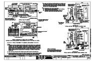
Figure 1. Details <strong>of</strong> <strong>the</strong> <strong>TxDOT</strong> <strong>F411</strong> <strong>Bridge</strong> Rail.
8<br />
Figure 1. Details <strong>of</strong> <strong>the</strong> <strong>TxDOT</strong> <strong>F411</strong> <strong>Bridge</strong> Rail (Continued).
Figure 2. <strong>TxDOT</strong> <strong>F411</strong> <strong>Bridge</strong> Rail before Test 442882-1.<br />
9
Figure 3. <strong>TxDOT</strong> <strong>F411</strong> <strong>Bridge</strong> Rail before Test 442882-2.<br />
10
<strong>the</strong> pavement surface. The rails were welded to <strong>the</strong> posts. The 1–1/4 inch (32 mm) thick posts<br />
were fabricated in <strong>the</strong> shape <strong>of</strong> <strong>the</strong> numeral “7” <strong>and</strong> were welded 11–1/2 inch × 12 inch ×<br />
1–1/2 inch (292 mm × 305 mm × 38 mm) thick baseplates. Each post was anchored to <strong>the</strong> curb<br />
using four 7/8 inch (22 mm) diameter A325 anchor bolts with a 7 inch × 11 inch × 1/4 inch<br />
(178 mm × 279 mm × 6 mm) thick anchor plate used for additional anchorage. The bridge railing<br />
system was supported by a cast-in-place concrete deck <strong>and</strong> curb. The curb was 14 inches<br />
(356 mm) wide <strong>and</strong> 9 inches (229 mm) high on <strong>the</strong> traffic side <strong>and</strong> 5-1/2 inches (140 mm) high<br />
on <strong>the</strong> field side. The top <strong>of</strong> <strong>the</strong> curb sloped downward approximately 14 degrees from<br />
horizontal toward <strong>the</strong> field side. The post plates were sloped in a similar fashion so that <strong>the</strong> two<br />
rail elements were flush with <strong>the</strong> traffic side face <strong>of</strong> <strong>the</strong> curb. The post plates <strong>and</strong> base plates<br />
were manufactured from A572 grade 50 steel. Gordon Specialities, Inc., <strong>of</strong> Hutchins, Texas,<br />
fabricated <strong>the</strong> bridge rail. TTI fabricated <strong>the</strong> anchor plates.<br />
The railing installation was constructed using 2 ft (0.6 m) long elliptical-shaped sleeve<br />
splices which were also manufactured from 6 inch (152 mm) diameter API-5LX52 pipe formed<br />
into an 8 inch × 4–7/8 inch (203 mm × 124 mm) elliptical shape. To obtain a secure fit <strong>of</strong> <strong>the</strong>se<br />
splices inside <strong>the</strong> elliptical rail pipe, small arch segments were removed from <strong>the</strong> upper <strong>and</strong><br />
lower areas <strong>of</strong> each splice sleeve with <strong>the</strong> two halves welded toge<strong>the</strong>r to obtain a secure fit inside<br />
<strong>the</strong> rails. The splices were constructed with a close fitting tolerance <strong>and</strong> provided approximately<br />
1–1/4 inch <strong>of</strong> rail expansion at each splice. These splices were located 1 ft (0.3 m) from posts 4<br />
<strong>and</strong> 7.<br />
A simulated concrete bridge deck cantilever <strong>and</strong> curb was constructed immediately<br />
adjacent to an existing concrete runway located at <strong>the</strong> TTI test facility. The total length <strong>of</strong> <strong>the</strong><br />
installation was 75 ft (22.9 m). The bridge deck cantilever was 2 ft-5 inches (0.7 m) in width <strong>and</strong><br />
8 inches (203 mm) thick <strong>and</strong> was rigidly attached to an existing concrete foundation at <strong>the</strong> testing<br />
facility. A 1 ft-2 inch (0.4 m) wide concrete curb, 9 inches (229 mm) high on <strong>the</strong> traffic side <strong>and</strong><br />
5-1/2 inches (140 mm) wide on <strong>the</strong> field side was cast on top <strong>of</strong> <strong>the</strong> concrete deck. Transverse<br />
reinforcement in <strong>the</strong> deck consisted <strong>of</strong> two layers <strong>of</strong> #5’s spaced 6 inches (152 mm) apart.<br />
Longitudinal reinforcement in <strong>the</strong> top layer <strong>of</strong> <strong>the</strong> deck consisted <strong>of</strong> two #4’s spaced 10 inches<br />
(254 mm) apart closest to <strong>the</strong> field side edge with a third bar located approximately 6-3/4 inches<br />
(171 mm) away. Longitudinal reinforcement in <strong>the</strong> bottom layer <strong>of</strong> <strong>the</strong> deck consisted <strong>of</strong> two<br />
#5’s located 3 inches (76 mm) apart closest to <strong>the</strong> field side edge with a third #5 bar located<br />
approximately 12 inches (305 mm) away. In addition to <strong>the</strong> deck reinforcement, #5 hoop-shaped<br />
“U” bars located 6 inches (152 mm) apart were cast in <strong>the</strong> deck for reinforcement for <strong>the</strong><br />
concrete curb. Longitudinal reinforcement in <strong>the</strong> curb consisted <strong>of</strong> two #5 bars equally spaced in<br />
<strong>the</strong> top <strong>of</strong> <strong>the</strong> “U” Bars. All reinforcement used in <strong>the</strong> top layer <strong>of</strong> <strong>the</strong> deck was epoxy coated.<br />
All o<strong>the</strong>r reinforcement was bare steel (not epoxy coated). All reinforcement was specified to<br />
have a minimum yield strength <strong>of</strong> 60 ksi.<br />
St<strong>and</strong>ard concrete compressive strength cylinders were cast for both <strong>the</strong> concrete deck<br />
<strong>and</strong> curb. For <strong>the</strong> concrete deck, strength tests performed at 11 days age resulted in an average<br />
compressive strength <strong>of</strong> 4155 psi. For <strong>the</strong> concrete curb, strength tests performed at 7 days age<br />
resulted in an average compressive strength <strong>of</strong> 3728 psi. Figure 4 provides additional details.<br />
Figure 5 shows photographs <strong>of</strong> <strong>the</strong> completed installations.<br />
11
12<br />
Figure 4. Details <strong>of</strong> <strong>the</strong> <strong>TxDOT</strong> <strong>T77</strong> <strong>Bridge</strong> Rail.
13<br />
Figure 4. Details <strong>of</strong> <strong>the</strong> <strong>TxDOT</strong> <strong>T77</strong> <strong>Bridge</strong> Rail (Continued).
14<br />
Figure 4. Details <strong>of</strong> <strong>the</strong> <strong>TxDOT</strong> <strong>T77</strong> <strong>Bridge</strong> Rail (Continued).
15<br />
Figure 4. Details <strong>of</strong> <strong>the</strong> <strong>TxDOT</strong> <strong>T77</strong> <strong>Bridge</strong> Rail (Continued).
16<br />
Figure 4. Details <strong>of</strong> <strong>the</strong> <strong>TxDOT</strong> <strong>T77</strong> <strong>Bridge</strong> Rail (Continued).
Figure 5. <strong>TxDOT</strong> <strong>F411</strong> <strong>Bridge</strong> Rail before Test 442882-3 <strong>and</strong> 4.<br />
17
CRASH TEST CONDITIONS<br />
According to NCHRP Report 350, two crash tests are recommended for test level 3<br />
evaluation <strong>of</strong> length <strong>of</strong> need longitudinal barriers:<br />
NCHRP Report 350 Test <strong>Design</strong>ation 3-10: 820C vehicle impacting <strong>the</strong> length<br />
<strong>of</strong> need section at a speed <strong>of</strong> 100 km/h at an impact angle <strong>of</strong> 20 degrees.<br />
NCHRP Report 350 Test <strong>Design</strong>ation 3-11: 2000P vehicle impacting <strong>the</strong> length<br />
<strong>of</strong> need section at a speed <strong>of</strong> 100 km/h at an impact angle <strong>of</strong> 25 degrees.<br />
The small car test is performed for evaluating <strong>the</strong> overall performance characteristics <strong>of</strong><br />
<strong>the</strong> length <strong>of</strong> need section <strong>of</strong> a longitudinal barrier in general, <strong>and</strong> occupant risks in particular.<br />
The pickup truck test is performed for <strong>the</strong> purpose <strong>of</strong> evaluating <strong>the</strong> strength <strong>of</strong> <strong>the</strong> section in<br />
containing <strong>and</strong> redirecting <strong>the</strong> larger <strong>and</strong> heavier vehicle. Occupant risks are <strong>of</strong> foremost concern<br />
in <strong>the</strong> evaluation <strong>of</strong> both tests. Tests 442882-1 through 3 all correspond to NCHRP Report 350<br />
test designation 3-11. Test 442882-4 corresponds to NCHRP Report 350 test designation 3-10.<br />
Researchers conducted <strong>the</strong> crash test <strong>and</strong> data analysis procedures in accordance with<br />
guidelines presented in NCHRP Report 350. Appendix C presents brief descriptions <strong>of</strong> <strong>the</strong>se<br />
procedures.<br />
EVALUATION CRITERIA<br />
The crash tests performed were evaluated in accordance with NCHRP Report 350. As<br />
stated in NCHRP Report 350, “Safety performance <strong>of</strong> a highway appurtenance cannot be<br />
measured directly but can be judged on <strong>the</strong> basis <strong>of</strong> three factors: structural adequacy, occupant<br />
risk, <strong>and</strong> vehicle trajectory after collision.” Accordingly, researchers used <strong>the</strong> safety evaluation<br />
criteria from Table 5.1 <strong>of</strong> NCHRP Report 350 to evaluate <strong>the</strong> crash tests reported herein.<br />
18
CHAPTER 3. CRASH TEST RESULTS<br />
TEST NO. 442882-1 (NCHRP Report 350 TEST NO. 3-11) ON THE TXDOT <strong>F411</strong><br />
BRIDGE RAIL<br />
Test Vehicle<br />
A 1997 Chevrolet Cheyenne 2500 pickup truck, shown in Figures 6 <strong>and</strong> 7, was used for<br />
<strong>the</strong> crash test. Test inertia mass <strong>of</strong> <strong>the</strong> vehicle was 4502 lb (2044 kg), <strong>and</strong> its gross static mass<br />
was 4502 lb (2044 kg). The height to <strong>the</strong> lower edge <strong>of</strong> <strong>the</strong> vehicle bumper was 18.1 inches<br />
(460 mm), <strong>and</strong> it was 26.8 inches (680 mm) to <strong>the</strong> upper edge <strong>of</strong> <strong>the</strong> bumper. Additional<br />
dimensions <strong>and</strong> information on <strong>the</strong> vehicle are given in Appendix D, Figure 34. The vehicle was<br />
directed into <strong>the</strong> installation using <strong>the</strong> cable reverse tow <strong>and</strong> guidance system, <strong>and</strong> was released<br />
to be free-wheeling <strong>and</strong> unrestrained just prior to impact.<br />
Wea<strong>the</strong>r Conditions<br />
Researchers performed <strong>the</strong> test on <strong>the</strong> morning <strong>of</strong> May 6, 2002. Wea<strong>the</strong>r conditions at<br />
<strong>the</strong> time <strong>of</strong> testing were as follows: Wind speed: 11 mi/h (18<br />
km/h); Wind direction: 335 degrees with respect to <strong>the</strong> vehicle<br />
(vehicle was traveling in a southwesterly direction); Temperature:<br />
81F (27 C); Relative humidity: 69 percent.<br />
Test Description<br />
The vehicle, traveling at a speed <strong>of</strong> 61.4 mi/h (98.8 km/h), impacted <strong>the</strong> <strong>TxDOT</strong> <strong>F411</strong> at<br />
an impact angle <strong>of</strong> 24.8 degrees at 5.1 inches (130 mm) upstream <strong>of</strong> opening 17. Shortly after<br />
impact, <strong>the</strong> vehicle hood deformed <strong>and</strong> at 0.018 s after impact, <strong>the</strong> vehicle began to redirect. The<br />
door on <strong>the</strong> passenger side separated slightly from <strong>the</strong> cab at 0.031 s <strong>and</strong> at 0.108 s, <strong>the</strong> left front<br />
tire became airborne. At 0.233 s, <strong>the</strong> vehicle became parallel with <strong>the</strong> bridge rail <strong>and</strong> was<br />
traveling at a speed <strong>of</strong> 42.1 mi/h (67.7 km/h). The left front tire returned to <strong>the</strong> ground at<br />
0.304 s. At 0.386 s, <strong>the</strong> vehicle lost contact with <strong>the</strong> bridge rail <strong>and</strong> was traveling at a speed <strong>of</strong><br />
36.0 mi/h (57.9 km/h) <strong>and</strong> an exit angle <strong>of</strong> 7.3 degrees. Brakes on <strong>the</strong> vehicle were applied at<br />
1.45 s after impact, <strong>and</strong> <strong>the</strong> vehicle subsequently came to rest 157.5 ft (48.0 m) downstream <strong>of</strong><br />
impact <strong>and</strong> 7.5 ft (2.3 m) behind <strong>the</strong> traffic face <strong>of</strong> <strong>the</strong> rail. Sequential photographs <strong>of</strong> <strong>the</strong> test<br />
period are shown in Appendix E, Figures 38 <strong>and</strong> 39.<br />
19
Figure 6. Vehicle/<strong>Bridge</strong> Rail Geometrics for Test 442882-1.<br />
20
Figure 7. Vehicle before Test 442882-1.<br />
21
Damage to Test Installation<br />
The <strong>TxDOT</strong> <strong>F411</strong> bridge rail sustained minimal cosmetic damage as shown in Figures 8<br />
<strong>and</strong> 9. There were tire marks <strong>and</strong> scrapes along <strong>the</strong> face <strong>of</strong> <strong>the</strong> bridge rail for a distance <strong>of</strong><br />
11.4 ft (3.5 m). No cracks were noted in <strong>the</strong> beam rail, window frames, or deck. No measurable<br />
deformation occurred, <strong>and</strong> <strong>the</strong> working width was 1.4 ft. (0.4 m).<br />
Vehicle Damage<br />
Figure 10 shows damage imparted to <strong>the</strong> vehicle. Structural damage included<br />
deformation <strong>of</strong> <strong>the</strong> right upper <strong>and</strong> lower A-arms, right spindle <strong>and</strong> tie rod ends, stabilizer bar,<br />
right front <strong>of</strong> <strong>the</strong> frame, A <strong>and</strong> B pillars, floor pan, <strong>and</strong> firewall. Also damaged were <strong>the</strong> front<br />
bumper, hood, radiator <strong>and</strong> fan, right front tire <strong>and</strong> wheel, right front quarter panel, right door<br />
<strong>and</strong> window glass, <strong>and</strong> right side bed. The ro<strong>of</strong> was deformed <strong>and</strong> <strong>the</strong> windshield was cracked.<br />
Maximum exterior crush to <strong>the</strong> vehicle was 25.6 inches (650 mm) in <strong>the</strong> front plane at <strong>the</strong> right<br />
front corner near bumper height. The vehicle was also crushed 20.9 inches (530 mm) in <strong>the</strong> side<br />
plane at <strong>the</strong> right front corner near bumper height. Maximum occupant compartment<br />
deformation was 8.3 inches (210 mm) in <strong>the</strong> right side door area. The right side floor pan area<br />
was deformed inward 7.3 inches (186 mm), <strong>and</strong> <strong>the</strong> right side firewall area was deformed inward<br />
6.9 inches (175 mm). Figure 11 shows photographs <strong>of</strong> <strong>the</strong> interior <strong>of</strong> <strong>the</strong> vehicle. Exterior<br />
vehicle crush <strong>and</strong> occupant compartment deformation are shown in Appendix D, Tables 5 <strong>and</strong> 6.<br />
Occupant Risk Factors<br />
Data from <strong>the</strong> tri-axial accelerometer, located at <strong>the</strong> vehicle center <strong>of</strong> gravity, were<br />
digitized to compute occupant impact velocity <strong>and</strong> ridedown accelerations. Only <strong>the</strong> occupant<br />
impact velocity <strong>and</strong> ridedown accelerations in <strong>the</strong> longitudinal axis are required from <strong>the</strong>se data<br />
for evaluation <strong>of</strong> criterion L <strong>of</strong> NCHRP Report 350. In <strong>the</strong> longitudinal direction, occupant<br />
impact velocity was 26.2 ft/s (8.0 m/s) at 0.100 s, maximum 0.010-s ridedown acceleration was –<br />
–6.0 g’s from 0.100 to 0.110 s, <strong>and</strong> <strong>the</strong> maximum 0.050-s average was –12.3 g’s between 0.062<br />
<strong>and</strong> 0.112 s. Figure 12 presents <strong>the</strong>se data <strong>and</strong> o<strong>the</strong>r information pertinent to <strong>the</strong> test. Vehicle<br />
angular displacements <strong>and</strong> accelerations versus time traces are shown in Appendix F, Figures 46<br />
<strong>and</strong> 50 through 55, respectively.<br />
Assessment <strong>of</strong> Test Results<br />
An assessment <strong>of</strong> <strong>the</strong> test based on <strong>the</strong> applicable NCHRP Report 350 safety evaluation<br />
criteria is provided below.<br />
<br />
Structural Adequacy<br />
A. Test article should contain <strong>and</strong> redirect <strong>the</strong> vehicle; <strong>the</strong> vehicle should not<br />
penetrate, underride, or override <strong>the</strong> installation although controlled lateral<br />
deflection <strong>of</strong> <strong>the</strong> test article is acceptable.<br />
22
Figure 8. After Impact Trajectory for Test 442882-1.<br />
23
Figure 9. Installation after Test 442882-1.<br />
24
Figure 10. Vehicle after Test 442882-1.<br />
25
Before Test<br />
After Test<br />
Figure 11. Interior <strong>of</strong> Vehicle for Test 442882-1.<br />
26
0.000 s 0.088 s 0.220 s 0.329 s<br />
27<br />
General Information<br />
Test Agency ...........................<br />
Test No. .................................<br />
Date .......................................<br />
Test Article<br />
Type .......................................<br />
Name .....................................<br />
Installation Length (ft) ............<br />
Material or Key Elements.......<br />
Soil Type <strong>and</strong> Condition.........<br />
Test Vehicle<br />
Type .......................................<br />
<strong>Design</strong>ation ............................<br />
Model .....................................<br />
Mass (lbs)<br />
Curb ...................................<br />
Test Inertial ........................<br />
Dummy...............................<br />
Gross Static .......................<br />
Texas Transportation Institute<br />
442882-1<br />
05/06/02<br />
<strong>Bridge</strong> Rail<br />
<strong>F411</strong> Aes<strong>the</strong>tic <strong>Bridge</strong> Rail<br />
76 (23.2 m)<br />
Concrete <strong>Bridge</strong> Rail With Two Concrete<br />
Rails And Aes<strong>the</strong>tic Openings<br />
Concrete Footing, Dry<br />
Production<br />
2000P<br />
1997 Chevrolet 2500 Pickup<br />
4778 (2170 kg)<br />
4502 (2044 kg)<br />
N/A<br />
4502 (2044 kg)<br />
Impact Conditions<br />
Speed (mi/h)................................ 61.4 (98.8 km/h)<br />
Angle (deg).................................. 24.8<br />
Exit Conditions<br />
Speed (mi/h)................................<br />
Angle (deg)..................................<br />
Occupant Risk Values<br />
Impact Velocity (ft/s)<br />
x-direction................................<br />
26.2 (8.0 m/s)<br />
y-direction................................ 23.0 (7.0 m/s)<br />
THIV (mph) ................................. 23.5 (37.8 km/h)<br />
Ridedown Accelerations (g's)<br />
x-direction................................ -6.0<br />
y-direction................................<br />
PHD (g=s).....................................<br />
ASI ..............................................<br />
Max. 0.050-s Average (g's)<br />
x-direction................................ -12.3<br />
y-direction................................ -10.5<br />
z-direction................................ 5.2<br />
36.0 (57.9 km/h)<br />
7.3<br />
-5.4<br />
6.8<br />
1.50<br />
Test Article Deflections (ft)<br />
Dynamic ................................<br />
Permanent ............................<br />
Working Width ......................<br />
Vehicle Damage<br />
Exterior<br />
VDS...................................<br />
CDC ..................................<br />
Maximum Exterior<br />
Vehicle Crush (in) .............<br />
Interior<br />
OCDI .................................<br />
Max. Occ. Compart.<br />
Deformation (in) ................<br />
Post-Impact Behavior<br />
(during 1.0 s after impact)<br />
Max. Yaw Angle (deg)...........<br />
Max. Pitch Angle (deg)..........<br />
Max. Roll Angle (deg) ...........<br />
None<br />
None<br />
1.41 (0.43 m)<br />
01FR2<br />
01RFAW3<br />
25.6 (650 mm)<br />
RF2222010<br />
8.3 (210 mm)<br />
-30.5<br />
-2.2<br />
4.1<br />
Figure 12. Summary <strong>of</strong> Results for Test 442882-1, NCHRP Report 350 Test 3-11.
Results:<br />
The <strong>TxDOT</strong> <strong>F411</strong> bridge rail contained <strong>and</strong> redirected <strong>the</strong> pickup truck.<br />
No measurable deflection occurred.<br />
<br />
Occupant Risk<br />
D. Detached elements, fragments, or o<strong>the</strong>r debris from <strong>the</strong> test article should not<br />
penetrate or show potential for penetrating <strong>the</strong> occupant compartment, or<br />
present an undue hazard to o<strong>the</strong>r traffic, pedestrians, or personnel in a work<br />
zone. Deformation <strong>of</strong>, or intrusions into, <strong>the</strong> occupant compartment that<br />
could cause serious injuries should not be permitted.<br />
Results:<br />
No detached elements, fragments, or o<strong>the</strong>r debris were present to penetrate<br />
or to show potential for penetrating <strong>the</strong> occupant compartment, or to<br />
present undue hazard to o<strong>the</strong>rs in <strong>the</strong> area. However, maximum<br />
deformation <strong>of</strong> <strong>the</strong> occupant compartment was 8.3 inches (210 mm) in <strong>the</strong><br />
door area, 7.3 inches (186 mm) in <strong>the</strong> right floor pan area, <strong>and</strong> 6.9 inches<br />
(175 mm) in <strong>the</strong> right firewall area.<br />
F. The vehicle should remain upright during <strong>and</strong> after collision although<br />
moderate roll, pitching, <strong>and</strong> yawing are acceptable.<br />
Results:<br />
The pickup truck remained upright during <strong>and</strong> after <strong>the</strong> collision period.<br />
<br />
Vehicle Trajectory<br />
K. After collision, it is preferable that <strong>the</strong> vehicle’s trajectory not intrude into<br />
adjacent traffic lanes.<br />
Results:<br />
The pickup truck came to rest 157.5 ft (48.0 m) downstream <strong>of</strong> impact <strong>and</strong><br />
7.5 ft (2.3 m) behind <strong>the</strong> traffic face <strong>of</strong> <strong>the</strong> bridge rail.<br />
L. The occupant impact velocity in <strong>the</strong> longitudinal direction should not exceed<br />
12 m/s, <strong>and</strong> <strong>the</strong> occupant ridedown acceleration in <strong>the</strong> longitudinal direction<br />
should not exceed 20 g’s.<br />
Results:<br />
Longitudinal occupant impact velocity was 26.2 ft/s (8.0 m/s), <strong>and</strong><br />
longitudinal ridedown acceleration was –6.0 g’s.<br />
M. The exit angle from <strong>the</strong> test article preferably should be less than 60 percent<br />
<strong>of</strong> <strong>the</strong> test impact angle, measured at time <strong>of</strong> vehicle loss <strong>of</strong> contact with <strong>the</strong><br />
test device.<br />
Results:<br />
Exit angle at loss <strong>of</strong> contact with <strong>the</strong> bridge rail was 7.3 degrees, which is<br />
29 percent <strong>of</strong> <strong>the</strong> impact angle.<br />
28
The following supplemental evaluation factors <strong>and</strong> terminology, as presented in <strong>the</strong><br />
FHWA memo entitled “Action: Identifying Acceptable Highway Safety Features,” were used for<br />
visual assessment <strong>of</strong> test results:<br />
Passenger Compartment Intrusion<br />
1. Windshield Intrusion<br />
a. No windshield contact e. Complete intrusion into<br />
b. Windshield contact, no damage passenger compartment<br />
c. Windshield contact, no intrusion f. Partial intrusion into<br />
d. Device embedded in windshield, no passenger compartment<br />
significant intrusion<br />
2. Body Panel Intrusion yes or no<br />
Loss <strong>of</strong> Vehicle Control<br />
1. Physical loss <strong>of</strong> control 3. Perceived threat to o<strong>the</strong>r vehicles<br />
2. Loss <strong>of</strong> windshield visibility 4. Debris on pavement<br />
Physical Threat to Workers or O<strong>the</strong>r Vehicles<br />
1. Harmful debris that could injure workers or o<strong>the</strong>rs in <strong>the</strong> area<br />
2. Harmful debris that could injure occupants in o<strong>the</strong>r vehicles<br />
No debris was present.<br />
Vehicle <strong>and</strong> Device Condition<br />
1. Vehicle Damage<br />
a. None d. Major dents to grill <strong>and</strong> body panels<br />
b. Minor scrapes, scratches or dents e. Major structural damage<br />
c. Significant cosmetic dents<br />
2. Windshield Damage<br />
a. None e. Shattered, remained intact but<br />
b. Minor chip or crack partially dislodged<br />
c. Broken, no interference with visibility f. Large portion removed<br />
d. Broken or shattered, visibility<br />
g. Completely removed<br />
restricted but remained intact<br />
3. Device Damage<br />
a. None d. Substantial, replacement parts<br />
b. Superficial needed for repair<br />
c. Substantial, but can be straightened e. Cannot be repaired<br />
29
TEST NO. 442882-2 (NCHRP Report 350 TEST NO. 3-11) ON THE MODIFIED TXDOT<br />
<strong>F411</strong> BRIDGE RAIL<br />
Test Vehicle<br />
A 1998 Chevrolet 2500 pickup truck, shown in Figures 13 <strong>and</strong> 14, was used for <strong>the</strong> crash<br />
test. Test inertia mass <strong>of</strong> <strong>the</strong> vehicle was 4518 lb (2052 kg), <strong>and</strong> its gross static mass was<br />
4518 lb (2052 kg). The height to <strong>the</strong> lower edge <strong>of</strong> <strong>the</strong> vehicle bumper was 14.0 inches<br />
(360 mm), <strong>and</strong> it was 25.2 inches (645 mm) to <strong>the</strong> upper edge <strong>of</strong> <strong>the</strong> bumper. Additional<br />
dimensions <strong>and</strong> information on <strong>the</strong> vehicle are given in Appendix D, Figure 35. The vehicle was<br />
directed into <strong>the</strong> installation using <strong>the</strong> cable reverse tow <strong>and</strong> guidance system, <strong>and</strong> was released<br />
to be free-wheeling <strong>and</strong> unrestrained just prior to impact.<br />
Wea<strong>the</strong>r Conditions<br />
Researchers performed <strong>the</strong> test on <strong>the</strong> morning <strong>of</strong> July 18, 2002. Wea<strong>the</strong>r conditions at<br />
<strong>the</strong> time <strong>of</strong> testing were as follows: Wind speed: 3 mi/h (5 km/h);<br />
Wind direction: 0 degrees with respect to <strong>the</strong> vehicle (vehicle was<br />
traveling in a southwesterly direction); Temperature: 88 F<br />
(31C); Relative humidity: 64 percent.<br />
Test Description<br />
The vehicle, traveling at a speed <strong>of</strong> 62.8 mi/h (101.1 km/h), impacted <strong>the</strong> modified<br />
<strong>TxDOT</strong> <strong>F411</strong> at an impact angle <strong>of</strong> 26.1 degrees at 2.3 inches (58 mm) downstream <strong>of</strong> opening<br />
17. Shortly after impact, <strong>the</strong> hood began to open <strong>and</strong> <strong>the</strong> top <strong>of</strong> <strong>the</strong> door on <strong>the</strong> driver’s side<br />
separated slightly from <strong>the</strong> door frame <strong>and</strong> at 0.033 s, <strong>the</strong> vehicle began to redirect. The right<br />
front tire became airborne at 0.079 s. At 0.202 s, <strong>the</strong> vehicle became parallel with <strong>the</strong> bridge rail<br />
<strong>and</strong> was traveling at a speed <strong>of</strong> 52.8 mi/h (84.9 km/h). At 0.287 s, <strong>the</strong> vehicle lost contact with<br />
<strong>the</strong> bridge rail <strong>and</strong> was traveling at a speed <strong>of</strong> 49.6 mi/h (79.9 km/h) <strong>and</strong> an exit angle <strong>of</strong><br />
4.5 degrees. The right front tire returned to <strong>the</strong> ground at 0.332 s. Brakes on <strong>the</strong> vehicle were<br />
applied at 1.5 s after impact, <strong>and</strong> <strong>the</strong> vehicle subsequently came to rest 221.4 ft (67.5 m)<br />
downstream <strong>of</strong> impact <strong>and</strong> 15.6 ft (4.8 m) forward <strong>of</strong> <strong>the</strong> traffic face <strong>of</strong> <strong>the</strong> rail. Sequential<br />
photographs <strong>of</strong> <strong>the</strong> test period are shown in Appendix E, Figures 40 <strong>and</strong> 41.<br />
Damage to Test Installation<br />
The modified <strong>TxDOT</strong> <strong>F411</strong> bridge rail sustained minimal cosmetic damage as shown in<br />
Figures 15 <strong>and</strong> 16. There were tire marks <strong>and</strong> scrapes along <strong>the</strong> face <strong>of</strong> <strong>the</strong> lower beam <strong>of</strong> <strong>the</strong><br />
bridge rail for a distance <strong>of</strong> 9.8 ft (3.0 m). No cracks were noted in <strong>the</strong> beam rail, window<br />
frames, or deck. No measurable deformation occurred, <strong>and</strong> <strong>the</strong> working width was 1.7 ft (0.5 m).<br />
31
Figure 13. Vehicle/<strong>Bridge</strong> Rail Geometrics for Test 442882-2.<br />
32
Figure 14. Vehicle before Test 442882-2.<br />
33
Vehicle Damage<br />
Figure 17 shows damage imparted to <strong>the</strong> vehicle. Structural damage included<br />
deformation <strong>of</strong> <strong>the</strong> left upper <strong>and</strong> lower A-arms, left rod ends, sway bar, left A- <strong>and</strong> B-pillars,<br />
floor pan, <strong>and</strong> firewall. Also damaged were <strong>the</strong> front bumper, grill, hood, radiator <strong>and</strong> fan, left<br />
front tire <strong>and</strong> wheel, left front quarter panel, left door, <strong>and</strong> left side bed. The ro<strong>of</strong> was deformed,<br />
<strong>and</strong> <strong>the</strong> windshield was cracked. Maximum exterior crush to <strong>the</strong> vehicle was 26.4 inches<br />
(670 mm) in <strong>the</strong> side plane at <strong>the</strong> left front corner 31.9 inches (810 mm) above ground level.<br />
The vehicle was also crushed 21.7 inches (550 mm) in <strong>the</strong> frontal plane at <strong>the</strong> left corner near<br />
bumper height. Maximum occupant compartment deformation was 4.6 inches (118 mm) in <strong>the</strong><br />
instrument panel area. The factory-installed opening, which accommodates <strong>the</strong> manual<br />
transmission floor shift, tore at <strong>the</strong> forward <strong>and</strong> rear corners, increasing <strong>the</strong> opening to 7.1 inches<br />
(180 mm) long <strong>and</strong> 6.3 inches (160 mm) wide. (The dimensions <strong>of</strong> <strong>the</strong> factory-installed opening<br />
for <strong>the</strong> floor shift was originally 5.6 inches [143 m] by 5.6 inches [143 mm]). No o<strong>the</strong>r<br />
separation in <strong>the</strong> floor pan or toe pan was noted. Figure 18 shows photographs <strong>of</strong> <strong>the</strong> interior <strong>of</strong><br />
<strong>the</strong> vehicle. Exterior vehicle crush <strong>and</strong> occupant compartment deformations are shown in<br />
Appendix D, Tables 7 <strong>and</strong> 8.<br />
Occupant Risk Factors<br />
Data from <strong>the</strong> tri-axial accelerometer, located at <strong>the</strong> vehicle center <strong>of</strong> gravity, were<br />
digitized to compute occupant impact velocity <strong>and</strong> ridedown accelerations. Only <strong>the</strong> occupant<br />
impact velocity <strong>and</strong> ridedown accelerations in <strong>the</strong> longitudinal axis are required from <strong>the</strong>se data<br />
for evaluation <strong>of</strong> criterion L <strong>of</strong> NCHRP Report 350. In <strong>the</strong> longitudinal direction, occupant<br />
impact velocity was 24.6 ft/s (7.5 m/s) at 0.095 s, maximum 0.010-s ridedown acceleration was –<br />
–6.7 g’s from 0.110 to 0.120 s, <strong>and</strong> <strong>the</strong> maximum 0.050-s average was –10.7 g’s between 0.041<br />
<strong>and</strong> 0.091 s. These data <strong>and</strong> o<strong>the</strong>r information pertinent to <strong>the</strong> test are presented in Figure 19.<br />
Vehicle angular displacements <strong>and</strong> accelerations versus time traces are shown in Appendix F,<br />
Figures 47 <strong>and</strong> 56 through 61, respectively.<br />
Assessment <strong>of</strong> Test Results<br />
An assessment <strong>of</strong> <strong>the</strong> test based on <strong>the</strong> applicable NCHRP Report 350 safety evaluation<br />
criteria is provided below.<br />
<br />
Structural Adequacy<br />
A. Test article should contain <strong>and</strong> redirect <strong>the</strong> vehicle; <strong>the</strong> vehicle should not<br />
penetrate, underride, or override <strong>the</strong> installation although controlled lateral<br />
deflection <strong>of</strong> <strong>the</strong> test article is acceptable.<br />
Results:<br />
The modified <strong>TxDOT</strong> <strong>F411</strong> bridge rail contained <strong>and</strong> redirected <strong>the</strong><br />
pickup truck. No measurable deflection occurred.<br />
34
Figure 15. After Impact Trajectory for Test 442882-2.<br />
35
Figure 16. Installation after Test 442882-2.<br />
36
Figure 17. Vehicle after Test 442882-2.<br />
37
Before Test<br />
After Test<br />
Figure 18. Interior <strong>of</strong> Vehicle for Test 442882-2.<br />
38
0.000 s 0.047 s 0.142 s 0.237 s<br />
39<br />
General Information<br />
Test Agency ...........................<br />
Test No. .................................<br />
Date .......................................<br />
Test Article<br />
Type .......................................<br />
Name .....................................<br />
Installation Length (ft) ............<br />
Material or Key Elements.......<br />
Soil Type <strong>and</strong> Condition.........<br />
Test Vehicle<br />
Type .......................................<br />
<strong>Design</strong>ation ............................<br />
Model .....................................<br />
Mass (lbs)<br />
Curb ...................................<br />
Test Inertial ........................<br />
Dummy...............................<br />
Gross Static .......................<br />
Texas Transportation Institute<br />
442882-2<br />
07/18/02<br />
<strong>Bridge</strong> Rail<br />
<strong>F411</strong> Aes<strong>the</strong>tic <strong>Bridge</strong> Rail<br />
76 (23.2 m)<br />
Concrete <strong>Bridge</strong> Rail With Two Concrete<br />
Rails And Aes<strong>the</strong>tic Openings<br />
Concrete Footing<br />
Production<br />
2000P<br />
1998 Chevrolet 2500 Pickup<br />
4569 (2075 kg)<br />
4518 (2052 kg)<br />
N/A<br />
4518 (2052 kg)<br />
Impact Conditions<br />
Speed (mi/h)............................ 62.8 (101.1 km/h)<br />
Angle (deg).............................. 26.1<br />
Exit Conditions<br />
Speed (mi/h)............................<br />
Angle (deg)..............................<br />
Occupant Risk Values<br />
Impact Velocity (ft/s)<br />
x-direction............................<br />
24.6 (7.5 m/s)<br />
y-direction............................ 28.5 (8.7 m/s)<br />
THIV (mph) ............................. 25.5 (41.0 km/h)<br />
Ridedown Accelerations (g's)<br />
x-direction............................<br />
y-direction............................<br />
PHD (g=s).................................<br />
ASI ..........................................<br />
Max. 0.050-s Average (g's)<br />
x-direction............................<br />
y-direction............................<br />
z-direction............................<br />
49.6 (79.9 km/h)<br />
4.5<br />
-6.7<br />
8.0<br />
8.6<br />
1.76<br />
-10.7<br />
13.8<br />
4.3<br />
Test Article Deflections (ft)<br />
Dynamic ................................<br />
Permanent ............................<br />
Working Width ......................<br />
Vehicle Damage<br />
Exterior<br />
VDS...................................<br />
CDC ..................................<br />
Maximum Exterior<br />
Vehicle Crush (in) .............<br />
Interior<br />
OCDI .................................<br />
Max. Occ. Compart.<br />
Deformation (in) ................<br />
Post-Impact Behavior<br />
(during 1.0 s after impact)<br />
Max. Yaw Angle (deg)...........<br />
Max. Pitch Angle (deg)..........<br />
Max. Roll Angle (deg) ...........<br />
None<br />
None<br />
1.71 (0.52 m)<br />
11FL3<br />
11LFAW3<br />
26.4 (670 mm)<br />
LF2010000<br />
4.6 (118 mm)<br />
33.5<br />
-2.9<br />
-7.6<br />
Figure 19. Summary <strong>of</strong> Results for Test 442882-2, NCHRP Report 350 Test 3-11.
Occupant Risk<br />
D. Detached elements, fragments, or o<strong>the</strong>r debris from <strong>the</strong> test article should not<br />
penetrate or show potential for penetrating <strong>the</strong> occupant compartment, or<br />
present an undue hazard to o<strong>the</strong>r traffic, pedestrians, or personnel in a work<br />
zone. Deformation <strong>of</strong>, or intrusions into, <strong>the</strong> occupant compartment that<br />
could cause serious injuries should not be permitted.<br />
Results:<br />
No detached elements, fragments, or o<strong>the</strong>r debris were present to penetrate<br />
or to show potential for penetrating <strong>the</strong> occupant compartment, or to<br />
present undue hazard to o<strong>the</strong>rs in <strong>the</strong> area. Deformation <strong>of</strong> <strong>the</strong> occupant<br />
compartment was 4.6 inches (118 mm) in <strong>the</strong> instrument panel area <strong>and</strong><br />
4.1 inches (105 mm) in <strong>the</strong> firewall area. The factory-installed opening,<br />
which accommodates <strong>the</strong> manual transmission floor shift, tore at <strong>the</strong><br />
forward <strong>and</strong> rear corners, increasing <strong>the</strong> opening to 7.1 inches (180 mm)<br />
long <strong>and</strong> 6.3 inches (160 mm) wide. (The dimensions <strong>of</strong> <strong>the</strong> factoryinstalled<br />
opening for <strong>the</strong> floor shift was originally 5.6 inches [143 m] by<br />
5.6 inches [143 mm]). No o<strong>the</strong>r separation in <strong>the</strong> floor pan or toe pan was<br />
noted.<br />
F. The vehicle should remain upright during <strong>and</strong> after collision although<br />
moderate roll, pitching, <strong>and</strong> yawing are acceptable.<br />
Results:<br />
The pickup truck remained upright during <strong>and</strong> after <strong>the</strong> collision period.<br />
<br />
Vehicle Trajectory<br />
K. After collision, it is preferable that <strong>the</strong> vehicle’s trajectory not intrude into<br />
adjacent traffic lanes.<br />
Results:<br />
The pickup truck came to rest 221.4 ft (67.5 m) downstream <strong>of</strong> impact <strong>and</strong><br />
15.6 ft (4.8 m) forward <strong>of</strong> <strong>the</strong> traffic face <strong>of</strong> <strong>the</strong> bridge rail.<br />
L. The occupant impact velocity in <strong>the</strong> longitudinal direction should not exceed<br />
12 m/s <strong>and</strong> <strong>the</strong> occupant ridedown acceleration in <strong>the</strong> longitudinal direction<br />
should not exceed 20 g’s.<br />
Results:<br />
Longitudinal occupant impact velocity was 24.6 ft/s (7.5 m/s), <strong>and</strong><br />
longitudinal ridedown acceleration was –6.7 g’s.<br />
M. The exit angle from <strong>the</strong> test article preferably should be less than 60 percent<br />
<strong>of</strong> <strong>the</strong> test impact angle, measured at time <strong>of</strong> vehicle loss <strong>of</strong> contact with <strong>the</strong><br />
test device.<br />
Results:<br />
Exit angle at loss <strong>of</strong> contact with <strong>the</strong> bridge rail was 4.5 degrees, which is<br />
17 percent <strong>of</strong> <strong>the</strong> impact angle.<br />
40
The following supplemental evaluation factors <strong>and</strong> terminology, as presented in <strong>the</strong><br />
FHWA memo entitled “Action: Identifying Acceptable Highway Safety Features,” were used for<br />
visual assessment <strong>of</strong> test results:<br />
Passenger Compartment Intrusion<br />
1. Windshield Intrusion<br />
a. No windshield contact e. Complete intrusion into<br />
b. Windshield contact, no damage passenger compartment<br />
c. Windshield contact, no intrusion f. Partial intrusion into<br />
d. Device embedded in windshield, no passenger compartment<br />
significant intrusion<br />
2. Body Panel Intrusion yes or no<br />
Loss <strong>of</strong> Vehicle Control<br />
1. Physical loss <strong>of</strong> control 3. Perceived threat to o<strong>the</strong>r vehicles<br />
2. Loss <strong>of</strong> windshield visibility 4. Debris on pavement<br />
Physical Threat to Workers or O<strong>the</strong>r Vehicles<br />
1. Harmful debris that could injure workers or o<strong>the</strong>rs in <strong>the</strong> area<br />
2. Harmful debris that could injure occupants in o<strong>the</strong>r vehicles<br />
No debris was present.<br />
Vehicle <strong>and</strong> Device Condition<br />
1. Vehicle Damage<br />
a. None d. Major dents to grill <strong>and</strong> body panels<br />
b. Minor scrapes, scratches or dents e. Major structural damage<br />
c. Significant cosmetic dents<br />
2. Windshield Damage<br />
a. None e. Shattered, remained intact but<br />
b. Minor chip or crack partially dislodged<br />
c. Broken, no interference with visibility f. Large portion removed<br />
d. Broken or shattered, visibility<br />
g. Completely removed<br />
restricted but remained intact<br />
3. Device Damage<br />
a. None d. Substantial, replacement parts<br />
b. Superficial needed for repair<br />
c. Substantial, but can be straightened e. Cannot be repaired<br />
41
TEST NO. 442882-3 (NCHRP Report 350 TEST NO. 3-11) ON THE TXDOT <strong>T77</strong> BRIDGE<br />
RAIL<br />
Test Vehicle<br />
A 1997 Chevrolet 2500 pickup truck, shown in Figures 20 <strong>and</strong> 21, was used for <strong>the</strong> crash<br />
test. Test inertia mass <strong>of</strong> <strong>the</strong> vehicle was 4500 lb (2043 kg), <strong>and</strong> its gross static mass was<br />
4500 lb (2043 kg). The height to <strong>the</strong> lower edge <strong>of</strong> <strong>the</strong> vehicle bumper was 14.4 inches<br />
(365 mm), <strong>and</strong> it was 25.6 inches (650 mm) to <strong>the</strong> upper edge <strong>of</strong> <strong>the</strong> bumper. Additional<br />
dimensions <strong>and</strong> information on <strong>the</strong> vehicle are given in Appendix D, Figure 36. The vehicle was<br />
directed into <strong>the</strong> installation using <strong>the</strong> cable reverse tow <strong>and</strong> guidance system, <strong>and</strong> was released<br />
to be free-wheeling <strong>and</strong> unrestrained just prior to impact.<br />
Wea<strong>the</strong>r Conditions<br />
Researchers performed <strong>the</strong> test on <strong>the</strong> morning <strong>of</strong> August 23, 2002. Wea<strong>the</strong>r conditions<br />
at <strong>the</strong> time <strong>of</strong> testing were as follows: Wind speed: 6 mi/h<br />
(9 km/h); Wind direction: 320 degrees with respect to <strong>the</strong> vehicle<br />
(vehicle was traveling in a southwesterly direction); Temperature:<br />
90 F (32 C); Relative humidity: 63 percent.<br />
Test Description<br />
The pickup truck, traveling at a speed <strong>of</strong> 60.8 mi/h (97.8 km/h), impacted <strong>the</strong> <strong>TxDOT</strong><br />
<strong>T77</strong> bridge rail at an impact angle <strong>of</strong> 24.2 degrees at 3.9 ft (1.2 m) upstream <strong>of</strong> post 4. At<br />
approximately 0.017 s after impact, <strong>the</strong> hood <strong>of</strong> <strong>the</strong> vehicle snapped loose. At 0.029 s post 4<br />
began to deflect toward <strong>the</strong> field side. The right front corner <strong>of</strong> <strong>the</strong> vehicle bumper pushed<br />
between <strong>the</strong> rail elements <strong>and</strong> contacted post 4 at 0.037 s. Post 3 began to deflect toward <strong>the</strong> field<br />
side at 0.039 s. At 0.041 s <strong>the</strong> pickup began to redirect, <strong>and</strong> at 0.057 s <strong>the</strong> passenger door<br />
deformed at <strong>the</strong> top <strong>of</strong> <strong>the</strong> door frame. At 0.069 s post 5 began to deflect toward <strong>the</strong> field side.<br />
The pickup began traveling parallel with <strong>the</strong> bridge rail at 0.224 s <strong>and</strong> was traveling at a speed <strong>of</strong><br />
47.7 mi/h (76.8 km/h). At 0.226 s <strong>the</strong> rail element between posts 3 <strong>and</strong> 4 began to deform. By<br />
0.427 s, <strong>the</strong> pickup lost contact with <strong>the</strong> rail element <strong>and</strong> was traveling at an exit speed <strong>of</strong><br />
44.7 mi/h (71.9 km/h) <strong>and</strong> an exit angle <strong>of</strong> 10.8 degrees. Brakes on <strong>the</strong> vehicle were applied at<br />
1.45 s after impact. The vehicle contacted a secondary barrier, yawed clockwise, <strong>and</strong> came to<br />
rest 187.7 ft (57.2 m) downstream <strong>of</strong> impact <strong>and</strong> 12.5 ft (3.8 m) forward <strong>of</strong> <strong>the</strong> traffic face <strong>of</strong> <strong>the</strong><br />
rail. Sequential photographs <strong>of</strong> <strong>the</strong> test period are shown in Appendix E, Figures 42 <strong>and</strong> 43.<br />
Damage to Test Installation<br />
Damage to <strong>the</strong> <strong>TxDOT</strong> <strong>T77</strong> bridge rail is shown in Figures 22 <strong>and</strong> 23. The concrete curb<br />
was broken out around post 4, <strong>and</strong> <strong>the</strong> post <strong>and</strong> rail were deflected toward <strong>the</strong> rear side 0.4 inches<br />
43
Figure 20. Vehicle/<strong>Bridge</strong> Rail Geometrics for Test 442882-3.<br />
44
Figure 21. Vehicle before Test 442882-3.<br />
45
(10 mm). The pickup snagged on <strong>the</strong> lower rail splice just upstream <strong>of</strong> post 4 <strong>and</strong> exp<strong>and</strong>ed <strong>the</strong><br />
joint 0.1 inch (3 mm). The lower rail element was also crushed 1.0 inch (25 mm). The pickup<br />
was in contact with <strong>the</strong> rail for 16.4 ft (5.0 m). Maximum deflection <strong>of</strong> <strong>the</strong> rail during <strong>the</strong> test<br />
was 1.8 inches (47 mm), <strong>and</strong> maximum permanent deformation was 0.4 inch (10 mm). Working<br />
width was 2.1 ft (0.6 m).<br />
Vehicle Damage<br />
The vehicle sustained damage as shown in Figure 24. The right side A-arms, sway bar,<br />
<strong>and</strong> right front <strong>of</strong> <strong>the</strong> frame rail were deformed. The A-pillar was deformed, <strong>the</strong>re was a crease<br />
in <strong>the</strong> top right side <strong>of</strong> <strong>the</strong> cab, <strong>and</strong> <strong>the</strong> top <strong>of</strong> <strong>the</strong> right door was pulled away from <strong>the</strong> cab<br />
11.4 inches (290 mm). Also damaged were <strong>the</strong> front bumper, hood, grill, radiator, fan, right<br />
front <strong>and</strong> left front quarter panel, right side bed, rear bumper, <strong>and</strong> right rear tire <strong>and</strong> wheel. The<br />
right front tire <strong>and</strong> exterior part <strong>of</strong> <strong>the</strong> wheel rim separated from <strong>the</strong> center part <strong>of</strong> <strong>the</strong> wheel rim<br />
(at <strong>the</strong> pop rivets). Small pieces <strong>of</strong> sheet metal were torn from <strong>the</strong> lower section <strong>of</strong> <strong>the</strong> cab <strong>and</strong><br />
<strong>the</strong> right rear side <strong>of</strong> <strong>the</strong> bed (2.4 inches × 5.9 inches [60 mm × 150 mm]). Maximum exterior<br />
crush to <strong>the</strong> vehicle was 30.7 inches (780 mm) in <strong>the</strong> front plane at <strong>the</strong> right front corner at<br />
bumper height. Maximum occupant compartment deformation was 8.7 inches (222 mm) in <strong>the</strong><br />
right front firewall. Photographs <strong>of</strong> <strong>the</strong> interior <strong>of</strong> <strong>the</strong> vehicle are shown in Figure 25. Exterior<br />
vehicle crush <strong>and</strong> occupant compartment deformations are shown in Appendix D, Tables 9 <strong>and</strong><br />
10.<br />
Occupant Risk Factors<br />
Data from <strong>the</strong> tri-axial accelerometer, located at <strong>the</strong> vehicle center <strong>of</strong> gravity, were<br />
digitized to compute occupant impact velocity <strong>and</strong> ridedown accelerations. Only <strong>the</strong> occupant<br />
impact velocity <strong>and</strong> ridedown accelerations in <strong>the</strong> longitudinal axis are required from <strong>the</strong>se data<br />
for evaluation <strong>of</strong> criterion L <strong>of</strong> NCHRP Report 350. In <strong>the</strong> longitudinal direction, occupant<br />
impact velocity was 21.6 ft/s (6.6 m/s) at 0.111 s, maximum 0.010-s ridedown acceleration was<br />
-5.6 g’s from 0.111 to 0.121 s, <strong>and</strong> <strong>the</strong> maximum 0.050-s average was –9.8 g’s between 0.027<br />
<strong>and</strong> 0.077 s. These data <strong>and</strong> o<strong>the</strong>r information pertinent to <strong>the</strong> test are presented in Figure 26.<br />
Vehicle angular displacements <strong>and</strong> accelerations versus time traces are shown in Appendix F,<br />
Figures 48 <strong>and</strong> 62 through 67, respectively.<br />
Assessment <strong>of</strong> Test Results<br />
An assessment <strong>of</strong> <strong>the</strong> test based on <strong>the</strong> applicable NCHRP Report 350 safety evaluation<br />
criteria is provided below.<br />
♦ Structural Adequacy<br />
A. Test article should contain <strong>and</strong> redirect <strong>the</strong> vehicle; <strong>the</strong> vehicle should not penetrate,<br />
underride, or override <strong>the</strong> installation although controlled lateral deflection <strong>of</strong> <strong>the</strong> test article is<br />
acceptable.<br />
46
Figure 22. After Impact Trajectory for Test 442882-3.<br />
47
Figure 23. Installation after Test 442882-3.<br />
48
Figure 24. Vehicle after Test 442882-3.<br />
49
Before Test<br />
After Test<br />
Figure 25. Interior <strong>of</strong> Vehicle for Test 442882-3.<br />
50
0.000 s 0.077 s 0.180 s 0.386 s<br />
51<br />
General Information<br />
Test Agency ...........................<br />
Test No. .................................<br />
Date .......................................<br />
Test Article<br />
Type .......................................<br />
Name .....................................<br />
Installation Length (ft) ............<br />
Material or Key Elements.......<br />
Soil Type <strong>and</strong> Condition.........<br />
Test Vehicle<br />
Type .......................................<br />
<strong>Design</strong>ation ............................<br />
Model .....................................<br />
Mass (lbs)<br />
Curb ...................................<br />
Test Inertial ........................<br />
Dummy...............................<br />
Gross Static .......................<br />
Texas Transportation Institute<br />
442882-3<br />
08/23/02<br />
<strong>Bridge</strong> Rail<br />
<strong>T77</strong> Aes<strong>the</strong>tic <strong>Bridge</strong> Rail<br />
75 (22.7 m)<br />
Tubular Steel Rail Elements Mounted<br />
On Steel A7" Shaped Posts<br />
Concrete Footing<br />
Production<br />
2000P<br />
1997 Chevrolet 2500 Pickup<br />
4723 (2145 kg)<br />
4500 (2043 kg)<br />
N/A<br />
4500 (2043 kg)<br />
Impact Conditions<br />
Speed (mi/h)............................ 60.8 (97.8 km/h)<br />
Angle (deg).............................. 24.2<br />
Exit Conditions<br />
Speed (mi/h)............................ 44.7 (71.9 km/h)<br />
Angle (deg).............................. 10.8<br />
Occupant Risk Values<br />
Impact Velocity (ft/s)<br />
x-direction............................ 21.6 (6.6 m/s)<br />
y-direction............................ 21.0 (6.4 m/s)<br />
THIV (mph) ............................. 19.9 (32.1 km/h)<br />
Ridedown Accelerations (g's)<br />
x-direction............................ -5.6<br />
y-direction............................ -13.5<br />
PHD (g=s)................................. 14.2<br />
ASI .......................................... 1.23<br />
Max. 0.050-s Average (g's)<br />
x-direction............................ -9.8<br />
y-direction............................ -9.4<br />
z-direction............................ -4.7<br />
Test Article Deflections (ft)<br />
Dynamic ................................<br />
Permanent ............................<br />
Working Width ......................<br />
Vehicle Damage<br />
Exterior<br />
VDS...................................<br />
CDC ..................................<br />
Maximum Exterior<br />
Vehicle Crush (in) .............<br />
Interior<br />
OCDI .................................<br />
Max. Occ. Compart.<br />
Deformation (in) ................<br />
Post-Impact Behavior<br />
(during 1.0 s after impact)<br />
Max. Yaw Angle (deg)...........<br />
Max. Pitch Angle (deg)..........<br />
Max. Roll Angle (deg) ...........<br />
0.18 (0.05 m)<br />
0.04 (0.01 m)<br />
2.10 (0.64 m)<br />
01FR3<br />
01FRAW3<br />
30.7 (780 mm)<br />
RF0020000<br />
8.7 (222 mm)<br />
-37.8<br />
4.1<br />
18.2<br />
Figure 26. Summary <strong>of</strong> Results for Test 442882-3, NCHRP Report 350 Test 3-11.
Results:<br />
The <strong>TxDOT</strong> <strong>T77</strong> bridge rail contained <strong>and</strong> redirected <strong>the</strong> pickup truck.<br />
The vehicle did not penetrate, underride, or override <strong>the</strong> bridge rail.<br />
Maximum dynamic deflection <strong>of</strong> <strong>the</strong> rail was 1.9 inches (47 mm).<br />
<br />
Occupant Risk<br />
D. Detached elements, fragments, or o<strong>the</strong>r debris from <strong>the</strong> test article should not<br />
penetrate or show potential for penetrating <strong>the</strong> occupant compartment, or<br />
present an undue hazard to o<strong>the</strong>r traffic, pedestrians, or personnel in a work<br />
zone. Deformation <strong>of</strong>, or intrusions into, <strong>the</strong> occupant compartment that<br />
could cause serious injuries should not be permitted.<br />
Results:<br />
No detached elements, fragments, or o<strong>the</strong>r debris were present to penetrate<br />
or to show potential for penetrating <strong>the</strong> occupant compartment, or to<br />
present undue hazard to o<strong>the</strong>rs in <strong>the</strong> area. Maximum occupant<br />
compartment deformation was 8.7 inches (222 mm).<br />
F. The vehicle should remain upright during <strong>and</strong> after collision although<br />
moderate roll, pitching, <strong>and</strong> yawing are acceptable.<br />
Results:<br />
The pickup truck remained upright during <strong>and</strong> after <strong>the</strong> collision event.<br />
<br />
Vehicle Trajectory<br />
K. After collision, it is preferable that <strong>the</strong> vehicle’s trajectory not intrude into<br />
adjacent traffic lanes.<br />
Results:<br />
The vehicle came to rest 187.6 ft (57.2 m) downstream <strong>of</strong> impact <strong>and</strong><br />
12.5 ft (3.8 m) forward <strong>of</strong> <strong>the</strong> face <strong>of</strong> <strong>the</strong> rail.<br />
L. The occupant impact velocity in <strong>the</strong> longitudinal direction should not exceed<br />
12 m/s <strong>and</strong> <strong>the</strong> occupant ridedown acceleration in <strong>the</strong> longitudinal direction<br />
should not exceed 20 g’s.<br />
Results:<br />
Longitudinal occupant impact velocity was 21.6 ft/s (6.6 m/s) <strong>and</strong><br />
longitudinal ridedown acceleration was –5.6 g’s.<br />
M. The exit angle from <strong>the</strong> test article preferably should be less than 60 percent<br />
<strong>of</strong> <strong>the</strong> test impact angle, measured at time <strong>of</strong> vehicle loss <strong>of</strong> contact with <strong>the</strong><br />
test device.<br />
Results:<br />
Exit angle at loss <strong>of</strong> contact with <strong>the</strong> bridge rail was 10.8 degrees, which is<br />
44 percent <strong>of</strong> <strong>the</strong> impact angle.<br />
52
The following supplemental evaluation factors <strong>and</strong> terminology, as presented in <strong>the</strong><br />
FHWA memo entitled “Action: Identifying Acceptable Highway Safety Features,” were used for<br />
visual assessment <strong>of</strong> test results:<br />
Passenger Compartment Intrusion<br />
1. Windshield Intrusion<br />
a. No windshield contact e. Complete intrusion into<br />
b. Windshield contact, no damage passenger compartment<br />
c. Windshield contact, no intrusion f. Partial intrusion into<br />
d. Device embedded in windshield, no passenger compartment<br />
significant intrusion<br />
2. Body Panel Intrusion yes or no<br />
Loss <strong>of</strong> Vehicle Control<br />
1. Physical loss <strong>of</strong> control 3. Perceived threat to o<strong>the</strong>r vehicles<br />
2. Loss <strong>of</strong> windshield visibility 4. Debris on pavement<br />
Physical Threat to Workers or O<strong>the</strong>r Vehicles<br />
1. Harmful debris that could injure workers or o<strong>the</strong>rs in <strong>the</strong> area<br />
2. Harmful debris that could injure occupants in o<strong>the</strong>r vehicles<br />
No debris was present.<br />
Vehicle <strong>and</strong> Device Condition<br />
1. Vehicle Damage<br />
a. None d. Major dents to grill <strong>and</strong> body panels<br />
b. Minor scrapes, scratches or dents e. Major structural damage<br />
c. Significant cosmetic dents<br />
2. Windshield Damage<br />
a. None e. Shattered, remained intact but<br />
b. Minor chip or crack (stress cracks) partially dislodged<br />
c. Broken, no interference with visibility f. Large portion removed<br />
d. Broken or shattered, visibility<br />
g. Completely removed<br />
restricted but remained intact<br />
3. Device Damage<br />
a. None d. Substantial, replacement parts<br />
b. Superficial needed for repair<br />
c. Substantial, but can be straightened e. Cannot be repaired<br />
53
TEST NO. 442882-4 (NCHRP Report 350 TEST NO. 3-10) ON THE TXDOT <strong>T77</strong> BRIDGE<br />
RAIL<br />
Test Vehicle<br />
A 1997 Geo Metro, shown in Figures 27 <strong>and</strong> 28, was used for <strong>the</strong> crash test. Test inertia<br />
mass <strong>of</strong> <strong>the</strong> vehicle was 1806 lb (820 kg), <strong>and</strong> its gross static mass was 1976 lb (897 kg). The<br />
height to <strong>the</strong> lower edge <strong>of</strong> <strong>the</strong> vehicle bumper was 15.7 inches (400 mm), <strong>and</strong> it was 20.7 inches<br />
(525 mm) to <strong>the</strong> upper edge <strong>of</strong> <strong>the</strong> bumper. Additional dimensions <strong>and</strong> information on <strong>the</strong><br />
vehicle are given in Appendix D, Figure 37. The vehicle was directed into <strong>the</strong> installation using<br />
<strong>the</strong> cable reverse tow <strong>and</strong> guidance system, <strong>and</strong> was released to be free-wheeling <strong>and</strong><br />
unrestrained just prior to impact.<br />
Wea<strong>the</strong>r Conditions<br />
Researchers performed <strong>the</strong> test on <strong>the</strong> morning <strong>of</strong> August 27, 2002. Wea<strong>the</strong>r conditions<br />
at <strong>the</strong> time <strong>of</strong> testing were as follows: Wind speed: 0 mi/h<br />
(0 km/h); Wind direction: 0 degrees with respect to <strong>the</strong> vehicle<br />
(vehicle was traveling in a southwesterly direction);<br />
Temperature: 88 F (31 C); Relative humidity: 69 percent.<br />
Test Description<br />
The small car, traveling at a speed <strong>of</strong> 61.6 mi/h (99.1 km/h), impacted <strong>the</strong> <strong>TxDOT</strong> <strong>T77</strong><br />
bridge rail 4.5 ft (1.4 m) upstream <strong>of</strong> post 7 at an impact angle <strong>of</strong> 20.4 degrees. At<br />
approximately 0.042 s after impact, <strong>the</strong> vehicle began to redirect, <strong>and</strong> at 0.070 s <strong>the</strong> driver side<br />
door glass shattered. The vehicle began traveling parallel with <strong>the</strong> rail at 0.132 s, <strong>and</strong> was<br />
traveling at a speed <strong>of</strong> 52.5 mi/h (84.5 km/h). At 0.304 s, <strong>the</strong> vehicle lost contact with <strong>the</strong> bridge<br />
rail <strong>and</strong> was traveling at a speed <strong>of</strong> 51.0 mi/h (82.0 km/h) <strong>and</strong> an exit angle <strong>of</strong> 12.1 degrees.<br />
Brakes on <strong>the</strong> vehicle were applied 1.7 s after impact. The vehicle subsequently came to rest<br />
202.7 ft (61.8 m) downstream <strong>of</strong> impact <strong>and</strong> 87.6 ft (26.7 m) forward <strong>of</strong> <strong>the</strong> traffic face <strong>of</strong> <strong>the</strong><br />
rail. Sequential photographs <strong>of</strong> <strong>the</strong> test period are shown in Appendix E, Figures 44 <strong>and</strong> 45.<br />
Damage to Test Installation<br />
The <strong>TxDOT</strong> <strong>T77</strong> bridge rail sustained damage as shown in Figures 29 <strong>and</strong> 30. The edge<br />
<strong>of</strong> <strong>the</strong> concrete curb was chipped <strong>of</strong>f in <strong>the</strong> area <strong>of</strong> initial contact. A hairline crack in <strong>the</strong><br />
concrete curb radiated from <strong>the</strong> right rear bolt at post 7, <strong>and</strong> <strong>the</strong> post <strong>and</strong> rail were deflected<br />
toward <strong>the</strong> rear side 0.4 inches (10 mm). The small car snagged on <strong>the</strong> upper <strong>and</strong> lower rail<br />
splice just upstream <strong>of</strong> post 7. The small car was in contact with <strong>the</strong> rail 9.7 ft (3.0 m). There<br />
was no measurable deflection <strong>of</strong> <strong>the</strong> rail during <strong>the</strong> test, <strong>and</strong> maximum permanent deformation<br />
was 0.4 inches (10 mm). Working width was 1.9 ft (0.6 m).<br />
55
Figure 27. Vehicle/<strong>Bridge</strong> Rail Geometrics for Test 442882-4.<br />
56
Figure 28. Vehicle before Test 442882-4.<br />
57
Vehicle Damage<br />
Figure 31 shows damage imparted to <strong>the</strong> vehicle. The inner CV joint on <strong>the</strong> left side was<br />
pulled out <strong>of</strong> <strong>the</strong> transmission, <strong>the</strong> lower left ball joint separated, <strong>and</strong> <strong>the</strong> left front <strong>and</strong> rear struts<br />
were deformed. A piece <strong>of</strong> sheet metal was torn from <strong>the</strong> left front quarter panel <strong>and</strong> from <strong>the</strong><br />
left door. The driver’s side door was pushed outward, <strong>and</strong> <strong>the</strong> top <strong>of</strong> <strong>the</strong> door was separated<br />
from <strong>the</strong> door frame 2.6 inches (65 mm). The windshield sustained stress cracks <strong>and</strong> <strong>the</strong>re was a<br />
small dent in <strong>the</strong> ro<strong>of</strong> just above <strong>the</strong> A-pillar. Also damaged were <strong>the</strong> front bumper, hood, grill,<br />
radiator, fan, left front quarter panel, left front tire <strong>and</strong> wheel rim, left door <strong>and</strong> glass, left rear<br />
quarter panel, <strong>and</strong> left rear taillight. Maximum exterior crush to <strong>the</strong> vehicle was 8.9 inches<br />
(230 mm) in <strong>the</strong> frontal plane at <strong>the</strong> left front corner near bumper height. Maximum occupant<br />
compartment deformation was 1.0 inch (25 mm) in <strong>the</strong> left front firewall area <strong>and</strong> <strong>the</strong> left side<br />
kickpanel area. Photographs <strong>of</strong> <strong>the</strong> interior <strong>of</strong> <strong>the</strong> vehicle are shown in Figure 32. Exterior<br />
vehicle crush <strong>and</strong> occupant compartment deformations are shown in Appendix D, Tables 11 <strong>and</strong><br />
12.<br />
Occupant Risk Factors<br />
Data from <strong>the</strong> accelerometer, located at <strong>the</strong> vehicle center <strong>of</strong> gravity (c.g.), were digitized<br />
for evaluation <strong>of</strong> occupant risk <strong>and</strong> were computed as follows. In <strong>the</strong> longitudinal direction, <strong>the</strong><br />
occupant impact velocity was 16.7 ft/s (5.1 m/s) at 0.082 s, <strong>the</strong> highest 0.010-s occupant<br />
ridedown acceleration was –2.3 g’s from 0.171 to 0.181 s, <strong>and</strong> <strong>the</strong> maximum 0.050-s average<br />
acceleration was –9.8 g’s between 0.026 <strong>and</strong> 0.076 s. In <strong>the</strong> lateral direction, <strong>the</strong> occupant<br />
impact velocity was 25.6 ft/s (7.8 m/s) at 0.082 s, <strong>the</strong> highest 0.010-s occupant ridedown<br />
acceleration was 10.0 g’s from 0.161 to 0.171 s, <strong>and</strong> <strong>the</strong> maximum 0.050-s average was 14.3 g’s<br />
between 0.027 <strong>and</strong> 0.077 s. These data <strong>and</strong> o<strong>the</strong>r information pertinent to <strong>the</strong> test are presented<br />
in Figure 33. Vehicle angular displacements <strong>and</strong> accelerations versus time traces are shown in<br />
Appendix F, Figures 49 <strong>and</strong> 68 through 73, respectively.<br />
Assessment <strong>of</strong> Test Results<br />
An assessment <strong>of</strong> <strong>the</strong> test based on <strong>the</strong> applicable NCHRP Report 350 safety evaluation<br />
criteria is provided below.<br />
<br />
Structural Adequacy<br />
A. Test article should contain <strong>and</strong> redirect <strong>the</strong> vehicle; <strong>the</strong> vehicle should not<br />
penetrate, underride, or override <strong>the</strong> installation although controlled lateral<br />
deflection <strong>of</strong> <strong>the</strong> test article is acceptable.<br />
Results:<br />
The <strong>TxDOT</strong> <strong>T77</strong> bridge rail contained <strong>and</strong> redirected <strong>the</strong> small car. The<br />
vehicle did not penetrate, underride, or override <strong>the</strong> installation.<br />
Maximum dynamic deflection <strong>of</strong> <strong>the</strong> rail was not measurable.<br />
58
Figure 29. After Impact Trajectory for Test 442882-4.<br />
59
Figure 30. Installation after Test 442882-4.<br />
60
Figure 31. Vehicle after Test 442882-4.<br />
61
Before Test<br />
After Test<br />
Figure 32. Interior <strong>of</strong> Vehicle for Test 442882-4.<br />
62
0.000 s 0.049 s 0.147 s 0.294 s<br />
63<br />
General Information<br />
Test Agency ...........................<br />
Test No. .................................<br />
Date .......................................<br />
Test Article<br />
Type .......................................<br />
Name .....................................<br />
Installation Length (ft) ............<br />
Material or Key Elements.......<br />
Soil Type <strong>and</strong> Condition.........<br />
Test Vehicle<br />
Type .......................................<br />
<strong>Design</strong>ation ............................<br />
Model .....................................<br />
Mass (lbs)<br />
Curb ...................................<br />
Test Inertial ........................<br />
Dummy...............................<br />
Gross Static .......................<br />
Texas Transportation Institute<br />
442882-4<br />
08/27/02<br />
<strong>Bridge</strong> Rail<br />
<strong>T77</strong> Aes<strong>the</strong>tic <strong>Bridge</strong> Rail<br />
75 (22.7 m)<br />
Tubular Steel Rail Elements Mounted On<br />
Steel A7" Shaped Posts<br />
Concrete Footing<br />
Production<br />
820C<br />
1997 Geo Metro<br />
1792 (814 kg)<br />
1806 (820 kg)<br />
169 (77 kg)<br />
1976 (897 kg)<br />
Impact Conditions<br />
Speed (mi/h)............................ 61.6 (99.1 km/h)<br />
Angle (deg).............................. 20.4<br />
Exit Conditions<br />
Speed (mi/h)............................ 51.0 (82.0 km/h)<br />
Angle (deg).............................. 12.1<br />
Occupant Risk Values<br />
Impact Velocity (ft/s)<br />
x-direction............................ 16.7 (5.1 m/s)<br />
y-direction............................ 25.6 (7.8 m/s)<br />
THIV (mph) ............................. 19.8 (31.9 km/h)<br />
Ridedown Accelerations (g's)<br />
x-direction............................ -2.3<br />
y-direction............................ 10.0<br />
PHD (g=s)................................. 10.0<br />
ASI .......................................... 1.79<br />
Max. 0.050-s Average (g's)<br />
x-direction............................ -9.8<br />
y-direction............................<br />
z-direction............................<br />
14.3<br />
-3.2<br />
Test Article Deflections (ft)<br />
Dynamic ................................<br />
Permanent ............................<br />
Working Width ......................<br />
Vehicle Damage<br />
Exterior<br />
VDS...................................<br />
CDC ..................................<br />
Maximum Exterior<br />
Vehicle Crush (in) .............<br />
Interior<br />
OCDI .................................<br />
Max. Occ. Compart.<br />
Deformation (in) ................<br />
Post-Impact Behavior<br />
(during 1.0 s after impact)<br />
Max. Yaw Angle (deg)...........<br />
Max. Pitch Angle (deg)..........<br />
Max. Roll Angle (deg) ...........<br />
None<br />
0.04 (0.01 m)<br />
1.90 (0.58 m)<br />
11FL2<br />
11LFEW2<br />
8.9 (230 mm)<br />
LF0010000<br />
1.0 (25 mm)<br />
38.2<br />
-3.2<br />
-14.2<br />
Figure 33. Summary <strong>of</strong> Results for Test 442882-4, NCHRP Report 350 Test 3-10.
Occupant Risk<br />
D. Detached elements, fragments, or o<strong>the</strong>r debris from <strong>the</strong> test article should not<br />
penetrate or show potential for penetrating <strong>the</strong> occupant compartment, or<br />
present an undue hazard to o<strong>the</strong>r traffic, pedestrians, or personnel in a work<br />
zone. Deformation <strong>of</strong>, or intrusions into, <strong>the</strong> occupant compartment that<br />
could cause serious injuries should not be permitted.<br />
Results:<br />
No detached elements, fragments, or o<strong>the</strong>r debris were present to penetrate<br />
or to show potential for penetrating <strong>the</strong> occupant compartment, or to<br />
present undue hazard to o<strong>the</strong>rs in <strong>the</strong> area. Maximum occupant<br />
compartment deformation was 1.0 inch (25 mm) in <strong>the</strong> left front firewall<br />
area <strong>and</strong> <strong>the</strong> left side kickpanel area.<br />
F. The vehicle should remain upright during <strong>and</strong> after collision although<br />
moderate roll, pitching, <strong>and</strong> yawing are acceptable.<br />
Results:<br />
The small car remained upright during <strong>and</strong> after <strong>the</strong> collision event.<br />
H. Occupant impact velocities should satisfy <strong>the</strong> following:<br />
Longitudinal <strong>and</strong> Lateral Occupant Impact Velocity – m/s<br />
Preferred<br />
Maximum<br />
9 12<br />
Results:<br />
Longitudinal occupant impact velocity was 16.7 ft/s (5.1 m/s),<br />
<strong>and</strong> lateral occupant impact velocity was 25.6 ft/s (7.8 m/s).<br />
I. Occupant ridedown accelerations should satisfy <strong>the</strong> following:<br />
Longitudinal <strong>and</strong> Lateral Occupant Ridedown Accelerations – g’s<br />
Preferred<br />
Maximum<br />
15 20<br />
Results:<br />
Longitudinal occupant ridedown acceleration was –2.3 g’s,<br />
<strong>and</strong> lateral occupant ridedown acceleration was 10.0 g’s.<br />
<br />
Vehicle Trajectory<br />
K. After collision, it is preferable that <strong>the</strong> vehicle’s trajectory not intrude into<br />
adjacent traffic lanes.<br />
Results:<br />
The vehicle came to rest 202.7 ft (61.8 m) downstream <strong>of</strong> impact <strong>and</strong><br />
87.6 ft (26.7 m) forward <strong>of</strong> <strong>the</strong> traffic face <strong>of</strong> <strong>the</strong> rail.<br />
M. The exit angle from <strong>the</strong> test article preferably should be less than 60 percent<br />
<strong>of</strong> <strong>the</strong> test impact angle, measured at time <strong>of</strong> vehicle loss <strong>of</strong> contact with <strong>the</strong><br />
test device.<br />
64
Results:<br />
Exit angle at loss <strong>of</strong> contact with <strong>the</strong> bridge rail was 12.1 degrees, which is<br />
60 percent <strong>of</strong> <strong>the</strong> impact angle.<br />
The following supplemental evaluation factors <strong>and</strong> terminology, as presented in <strong>the</strong><br />
FHWA memo entitled “Action: Identifying Acceptable Highway Safety Features,” were used for<br />
visual assessment <strong>of</strong> test results:<br />
Passenger Compartment Intrusion<br />
1. Windshield Intrusion<br />
a. No windshield contact e. Complete intrusion into<br />
b. Windshield contact, no damage passenger compartment<br />
c. Windshield contact, no intrusion f. Partial intrusion into<br />
d. Device embedded in windshield, no passenger compartment<br />
significant intrusion<br />
2. Body Panel Intrusion yes or no<br />
Loss <strong>of</strong> Vehicle Control<br />
1. Physical loss <strong>of</strong> control 3. Perceived threat to o<strong>the</strong>r vehicles<br />
2. Loss <strong>of</strong> windshield visibility 4. Debris on pavement<br />
Physical Threat to Workers or O<strong>the</strong>r Vehicles<br />
1. Harmful debris that could injure workers or o<strong>the</strong>rs in <strong>the</strong> area<br />
2. Harmful debris that could injure occupants in o<strong>the</strong>r vehicles<br />
No debris was present.<br />
Vehicle <strong>and</strong> Device Condition<br />
1. Vehicle Damage<br />
a. None d. Major dents to grill <strong>and</strong> body panels<br />
b. Minor scrapes, scratches or dents e. Major structural damage<br />
c. Significant cosmetic dents<br />
2. Windshield Damage<br />
a. None e. Shattered, remained intact but<br />
b. Minor chip or crack (stress cracks) partially dislodged<br />
c. Broken, no interference with visibility f. Large portion removed<br />
d. Broken or shattered, visibility<br />
g. Completely removed<br />
restricted but remained intact<br />
3. Device Damage<br />
a. None d. Substantial, replacement parts<br />
b. Superficial needed for repair<br />
c. Substantial, but can be straightened e. Cannot be repaired<br />
65
CHAPTER 4. SUMMARY AND CONCLUSIONS<br />
SUMMARY OF RESULTS<br />
<strong>F411</strong> <strong>Bridge</strong> Rail<br />
Test 442882-1 (NCHRP Report 350 test 3-11)<br />
The <strong>TxDOT</strong> <strong>F411</strong> bridge rail contained <strong>and</strong> redirected <strong>the</strong> pickup truck. No measurable<br />
deflection occurred. No detached elements, fragments, or o<strong>the</strong>r debris were present to penetrate<br />
or to show potential for penetrating <strong>the</strong> occupant compartment, or to present undue hazard to<br />
o<strong>the</strong>rs in <strong>the</strong> area. However, maximum deformation <strong>of</strong> <strong>the</strong> occupant compartment was<br />
8.3 inches (210 mm) in <strong>the</strong> door area, 7.3 inches (186 mm) in <strong>the</strong> right floor pan area, <strong>and</strong><br />
6.9 inches (175 mm) in <strong>the</strong> right firewall area. The pickup truck remained upright during <strong>and</strong><br />
after <strong>the</strong> collision period. The pickup truck came to rest 157.5 ft (48.0 m) downstream <strong>of</strong> impact<br />
<strong>and</strong> 7.5 ft (2.3 m) behind <strong>the</strong> traffic face <strong>of</strong> <strong>the</strong> bridge rail. Longitudinal occupant impact<br />
velocity was 26.2 ft/s (8.0 m/s) <strong>and</strong> longitudinal ridedown acceleration was –6.0 g’s. Exit angle<br />
at loss <strong>of</strong> contact with <strong>the</strong> bridge rail was 7.3 degrees, which is 29 percent <strong>of</strong> <strong>the</strong> impact angle.<br />
Test 442882-2 (NCHRP Report 350 test 3-11)<br />
The modified <strong>TxDOT</strong> <strong>F411</strong> bridge rail contained <strong>and</strong> redirected <strong>the</strong> pickup truck. No<br />
measurable deflection occurred. No detached elements, fragments, or o<strong>the</strong>r debris were present<br />
to penetrate or to show potential for penetrating <strong>the</strong> occupant compartment, or to present undue<br />
hazard to o<strong>the</strong>rs in <strong>the</strong> area. Deformation <strong>of</strong> <strong>the</strong> occupant compartment was 4.6 inches (118 mm)<br />
in <strong>the</strong> instrument panel area <strong>and</strong> 4.1 inches (105 mm) in <strong>the</strong> firewall area. The factory-installed<br />
opening, which accommodates <strong>the</strong> manual transmission floor shift, tore at <strong>the</strong> forward <strong>and</strong> rear<br />
corners, increasing <strong>the</strong> opening to 7.1 inches (180 mm) long <strong>and</strong> 6.3 inches (160 mm) wide.<br />
(The dimensions <strong>of</strong> <strong>the</strong> factory-installed opening for <strong>the</strong> floor shift was originally 5.6 inches<br />
(143 m) by 5.6 inches [143 mm]). No o<strong>the</strong>r separation in <strong>the</strong> floor pan or toe pan was noted. The<br />
pickup truck remained upright during <strong>and</strong> after <strong>the</strong> collision period. The pickup truck came to<br />
rest 221.4 ft (67.5 m) downstream <strong>of</strong> impact <strong>and</strong> 15.6 ft (4.8 m) forward <strong>of</strong> <strong>the</strong> traffic face <strong>of</strong> <strong>the</strong><br />
bridge rail. Longitudinal occupant impact velocity was 24.6 ft/s (7.5 m/s) <strong>and</strong> longitudinal<br />
ridedown acceleration was –6.7 g’s. Exit angle at loss <strong>of</strong> contact with <strong>the</strong> bridge rail was 4.5<br />
degrees, which is 17 percent <strong>of</strong> <strong>the</strong> impact angle.<br />
<strong>T77</strong> <strong>Bridge</strong> Rail<br />
Test 442882-3 (NCHRP Report 350 test 3-11)<br />
The <strong>TxDOT</strong> <strong>T77</strong> bridge rail contained <strong>and</strong> redirected <strong>the</strong> pickup truck. The vehicle did<br />
not penetrate, underride, or override <strong>the</strong> bridge rail. Maximum dynamic deflection <strong>of</strong> <strong>the</strong> rail<br />
was 1.9 inches (47 mm). No detached elements, fragments, or o<strong>the</strong>r debris were present to<br />
penetrate or to show potential for penetrating <strong>the</strong> occupant compartment, or to present undue<br />
hazard to o<strong>the</strong>rs in <strong>the</strong> area. Maximum occupant compartment deformation was 8.7 inches<br />
(222 mm). The pickup truck remained upright during <strong>and</strong> after <strong>the</strong> collision event. The vehicle<br />
67
came to rest 187.6 ft (57.2 m) downstream <strong>of</strong> impact <strong>and</strong> 12.5 ft (3.8 m) forward <strong>of</strong> <strong>the</strong> face <strong>of</strong><br />
<strong>the</strong> rail. Longitudinal occupant impact velocity was 21.6 ft/s (6.6 m/s), <strong>and</strong> longitudinal<br />
ridedown acceleration was –5.6 g’s. Exit angle at loss <strong>of</strong> contact was 10.8 degrees, which was<br />
44 percent <strong>of</strong> <strong>the</strong> impact angle.<br />
Test 442882-4 (NCHRP Report 350 test 3-10)<br />
The <strong>TxDOT</strong> <strong>T77</strong> bridge rail contained <strong>and</strong> redirected <strong>the</strong> small car. The vehicle did not<br />
penetrate, underride, or override <strong>the</strong> installation. Maximum dynamic deflection <strong>of</strong> <strong>the</strong> rail was<br />
not measurable. No detached elements, fragments, or o<strong>the</strong>r debris were present to penetrate or to<br />
show potential for penetrating <strong>the</strong> occupant compartment, or to present undue hazard to o<strong>the</strong>rs in<br />
<strong>the</strong> area. Maximum occupant compartment deformation was 1.0 inches (25 mm) in <strong>the</strong> left front<br />
firewall area <strong>and</strong> <strong>the</strong> left side kickpanel area. The small car remained upright during <strong>and</strong> after<br />
<strong>the</strong> collision event. Longitudinal occupant impact velocity was 16.7 ft/s (5.1 m/s) <strong>and</strong> lateral<br />
occupant impact velocity was 25.6 ft/s (7.8 m/s). Longitudinal occupant ridedown acceleration<br />
was –2.3 g’s, <strong>and</strong> lateral occupant ridedown acceleration was 10.0 g’s. The vehicle came to rest<br />
202.7 ft (61.8 m) downstream <strong>of</strong> impact <strong>and</strong> 87.6 ft (26.7 m) forward <strong>of</strong> <strong>the</strong> traffic face <strong>of</strong> <strong>the</strong><br />
rail. Exit angle at loss <strong>of</strong> contact was 12.1 degrees, which was 60 percent <strong>of</strong> <strong>the</strong> impact angle.<br />
CONCLUSIONS<br />
As shown in Table 1, <strong>the</strong> first test on <strong>the</strong> <strong>F411</strong> bridge rail did not meet <strong>the</strong> requirements<br />
for occupant risk for NCHRP Report 350 test 3-11. The modified <strong>F411</strong> bridge rail did meet <strong>the</strong><br />
required specifications for NCHRP Report 350 test 3-11, as summarized in Table 2.<br />
The <strong>T77</strong> bridge rail did not meet <strong>the</strong> occupant risk requirements for NCHRP Report 350<br />
test 3-11 due to excessive occupant compartment deformation; however, <strong>the</strong> <strong>T77</strong> bridge rail did<br />
perform acceptably during NCHRP Report 350 test 3-10. Tables 3 <strong>and</strong> 4 summarize <strong>the</strong><br />
evaluation <strong>of</strong> <strong>the</strong>se two tests on <strong>the</strong> <strong>TxDOT</strong> <strong>T77</strong> bridge rail.<br />
IMPLEMENTATION STATEMENT<br />
TTI researchers recommend implementation <strong>of</strong> <strong>the</strong> use <strong>of</strong> <strong>the</strong> modified <strong>F411</strong> bridge rail<br />
as per <strong>the</strong> design used in <strong>the</strong> second crash test. The rail had been modified by enclosing <strong>the</strong> open<br />
space beneath <strong>the</strong> lower rail face with concrete to make it flush with <strong>the</strong> lower rail. Enclosing <strong>the</strong><br />
bottom <strong>of</strong> <strong>the</strong> rail increased <strong>the</strong> effective surface contact area <strong>of</strong> <strong>the</strong> installation.<br />
TTI researchers <strong>and</strong> <strong>TxDOT</strong> personnel will pursue development <strong>of</strong> modifications to<br />
ensure <strong>the</strong> <strong>T77</strong> bridge rail performs in accordance with <strong>the</strong> evaluation criteria <strong>of</strong> NCHRP Report<br />
350. Tentatively, modifications include improvement in <strong>the</strong> rail splice connection <strong>and</strong> increased<br />
wall thickness <strong>of</strong> <strong>the</strong> rail member. One additional NCHRP Report 350 crash test (3-11) will be<br />
required to evaluate <strong>the</strong> performance <strong>of</strong> <strong>the</strong> <strong>T77</strong> bridge rail with <strong>the</strong>se modifications.<br />
68
Table 1. Performance <strong>Evaluation</strong> Summary for Test 442882-1, NCHRP Report 350 Test 3-11.<br />
69<br />
Test Agency: Texas Transportation Institute Test No.: 442882-1 Test Date: 05/06/2002<br />
NCHRP Report 350 Test 3-11 <strong>Evaluation</strong> Criteria Test Results Assessment<br />
Structural Adequacy<br />
A. Test article should contain <strong>and</strong> redirect <strong>the</strong> vehicle;<br />
<strong>the</strong> vehicle should not penetrate, underride, or<br />
override <strong>the</strong> installation although controlled lateral<br />
deflection <strong>of</strong> <strong>the</strong> test article is acceptable.<br />
Occupant Risk<br />
D. Detached elements, fragments, or o<strong>the</strong>r debris from<br />
<strong>the</strong> test article should not penetrate or show potential<br />
for penetrating <strong>the</strong> occupant compartment, or present<br />
an undue hazard to o<strong>the</strong>r traffic, pedestrians, or<br />
personnel in a work zone. Deformations <strong>of</strong>, or<br />
intrusions into, <strong>the</strong> occupant compartment that could<br />
cause serious injuries should not be permitted.<br />
F. The vehicle should remain upright during <strong>and</strong> after<br />
collision although moderate roll, pitching, <strong>and</strong><br />
yawing are acceptable.<br />
Vehicle Trajectory<br />
K. After collision it is preferable that <strong>the</strong> vehicle’s<br />
trajectory not intrude into adjacent traffic lanes.<br />
L. The occupant impact velocity in <strong>the</strong> longitudinal<br />
direction should not exceed 12 m/s <strong>and</strong> <strong>the</strong> occupant<br />
ridedown acceleration in <strong>the</strong> longitudinal direction<br />
should not exceed 20 g’s.<br />
M. The exit angle from <strong>the</strong> test article preferably should<br />
be less than 60 percent <strong>of</strong> test impact angle,<br />
measured at time <strong>of</strong> vehicle loss <strong>of</strong> contact with test<br />
device.<br />
*Criterion K <strong>and</strong> M are preferable, not required.<br />
The <strong>TxDOT</strong> <strong>F411</strong> bridge rail contained <strong>and</strong><br />
redirected <strong>the</strong> pickup truck. No measurable<br />
deflection occurred.<br />
No detached elements, fragments, or o<strong>the</strong>r<br />
debris were present to penetrate or to show<br />
potential for penetrating <strong>the</strong> occupant<br />
compartment, or to present undue hazard to<br />
o<strong>the</strong>rs in <strong>the</strong> area. Maximum deformation <strong>of</strong><br />
<strong>the</strong> occupant compartment was 8.3 inches<br />
(210 mm) in <strong>the</strong> door area.<br />
The pickup truck remained upright during<br />
<strong>and</strong> after <strong>the</strong> collision period.<br />
The pickup truck came to rest 7.5 ft (2.3 m)<br />
behind <strong>the</strong> traffic face <strong>of</strong> <strong>the</strong> bridge rail.<br />
Longitudinal occupant impact velocity was<br />
26.2 ft/s (8.0 m/s), <strong>and</strong> longitudinal<br />
ridedown acceleration was –6.0 g’s.<br />
Exit angle at loss <strong>of</strong> contact with <strong>the</strong> bridge<br />
rail was 7.3 degrees, which is 29 percent <strong>of</strong><br />
<strong>the</strong> impact angle.<br />
Pass<br />
Fail<br />
Pass<br />
Pass*<br />
Pass<br />
Pass*
Table 2. Performance <strong>Evaluation</strong> Summary for Test 442882-2, NCHRP Report 350 Test 3-11.<br />
70<br />
Test Agency: Texas Transportation Institute Test No.: 442882-2 Test Date: 07/18/2002<br />
NCHRP Report 350 Test 3-11 <strong>Evaluation</strong> Criteria Test Results Assessment<br />
Structural Adequacy<br />
A. Test article should contain <strong>and</strong> redirect <strong>the</strong> vehicle;<br />
<strong>the</strong> vehicle should not penetrate, underride, or<br />
override <strong>the</strong> installation although controlled lateral<br />
deflection <strong>of</strong> <strong>the</strong> test article is acceptable.<br />
Occupant Risk<br />
D. Detached elements, fragments, or o<strong>the</strong>r debris from<br />
<strong>the</strong> test article should not penetrate or show potential<br />
for penetrating <strong>the</strong> occupant compartment, or present<br />
an undue hazard to o<strong>the</strong>r traffic, pedestrians, or<br />
personnel in a work zone. Deformations <strong>of</strong>, or<br />
intrusions into, <strong>the</strong> occupant compartment that could<br />
cause serious injuries should not be permitted.<br />
F. The vehicle should remain upright during <strong>and</strong> after<br />
collision although moderate roll, pitching, <strong>and</strong> yawing<br />
are acceptable.<br />
Vehicle Trajectory<br />
K. After collision it is preferable that <strong>the</strong> vehicle’s<br />
trajectory not intrude into adjacent traffic lanes.<br />
L. The occupant impact velocity in <strong>the</strong> longitudinal<br />
direction should not exceed 12 m/s <strong>and</strong> <strong>the</strong> occupant<br />
ridedown acceleration in <strong>the</strong> longitudinal direction<br />
should not exceed 20 g’s.<br />
M. The exit angle from <strong>the</strong> test article preferably should<br />
be less than 60 percent <strong>of</strong> test impact angle, measured<br />
at time <strong>of</strong> vehicle loss <strong>of</strong> contact with test device.<br />
*Criterion K <strong>and</strong> M are preferable, not required.<br />
The modified <strong>TxDOT</strong> <strong>F411</strong> bridge rail contained <strong>and</strong><br />
redirected <strong>the</strong> pickup truck. No measurable deflection<br />
occurred.<br />
No detached elements, fragments, or o<strong>the</strong>r debris were<br />
present. Deformation <strong>of</strong> <strong>the</strong> occupant compartment was 4.6<br />
inches (118 mm) in <strong>the</strong> instrument panel area <strong>and</strong> 4.1 inches<br />
(105 mm) in <strong>the</strong> firewall area. The factory-installed opening,<br />
which accommodates <strong>the</strong> manual transmission floor shift,<br />
tore at <strong>the</strong> forward <strong>and</strong> rear corners, increasing <strong>the</strong> opening<br />
7.1 inches (180 mm) long <strong>and</strong> 6.3 inches (160 mm) wide<br />
(original dimensions <strong>of</strong> opening were 5.6 inches x 5.6 inches<br />
[143 mm x 143 mm]). No o<strong>the</strong>r separation in <strong>the</strong> floor pan<br />
or toe pan was noted.<br />
The pickup truck remained upright during <strong>and</strong> after <strong>the</strong><br />
collision period.<br />
The pickup truck came to rest 221.4 ft (67.5 m) downstream<br />
<strong>of</strong> impact <strong>and</strong> 15.6 ft (4.8 m) forward <strong>of</strong> <strong>the</strong> traffic face <strong>of</strong><br />
<strong>the</strong> bridge rail.<br />
Longitudinal occupant impact velocity was 24.6 ft/s<br />
(7.5 m/s), <strong>and</strong> longitudinal ridedown acceleration was<br />
–6.0 g’s.<br />
Exit angle at loss <strong>of</strong> contact with <strong>the</strong> bridge rail was 4.5<br />
degrees, which is 17 percent <strong>of</strong> <strong>the</strong> impact angle.<br />
Pass<br />
Pass<br />
Pass<br />
Fail*<br />
Pass<br />
Pass*
Table 3. Performance <strong>Evaluation</strong> Summary for Test 442882-3, NCHRP Report 350 Test 3-11.<br />
71<br />
Test Agency: Texas Transportation Institute Test No.: 442882-3 Test Date: 08/23/2002<br />
NCHRP Report 350 Test 3-11 <strong>Evaluation</strong> Criteria Test Results Assessment<br />
Structural Adequacy<br />
A. Test article should contain <strong>and</strong> redirect <strong>the</strong> vehicle; <strong>the</strong><br />
vehicle should not penetrate, underride, or override <strong>the</strong><br />
installation although controlled lateral deflection <strong>of</strong> <strong>the</strong><br />
test article is acceptable.<br />
Occupant Risk<br />
D. Detached elements, fragments, or o<strong>the</strong>r debris from <strong>the</strong><br />
test article should not penetrate or show potential for<br />
penetrating <strong>the</strong> occupant compartment, or present an<br />
undue hazard to o<strong>the</strong>r traffic, pedestrians, or personnel in<br />
a work zone. Deformations <strong>of</strong>, or intrusions into, <strong>the</strong><br />
occupant compartment that could cause serious injuries<br />
should not be permitted.<br />
F. The vehicle should remain upright during <strong>and</strong> after<br />
collision although moderate roll, pitching, <strong>and</strong> yawing are<br />
acceptable.<br />
Vehicle Trajectory<br />
K. After collision it is preferable that <strong>the</strong> vehicle’s trajectory<br />
not intrude into adjacent traffic lanes.<br />
L. The occupant impact velocity in <strong>the</strong> longitudinal<br />
direction should not exceed 12 m/s, <strong>and</strong> <strong>the</strong> occupant<br />
ridedown acceleration in <strong>the</strong> longitudinal direction should<br />
not exceed 20 g’s.<br />
M. The exit angle from <strong>the</strong> test article preferably should be<br />
less than 60 percent <strong>of</strong> test impact angle, measured at<br />
time <strong>of</strong> vehicle loss <strong>of</strong> contact with test device.<br />
*Criterion K <strong>and</strong> M are preferable, not required.<br />
The <strong>TxDOT</strong> <strong>T77</strong> bridge rail contained <strong>and</strong><br />
redirected <strong>the</strong> pickup truck. The vehicle did not<br />
penetrate, underride, or override <strong>the</strong> bridge rail.<br />
Maximum dynamic deflection <strong>of</strong> <strong>the</strong> rail was<br />
1.9 inches (47 mm).<br />
No detached elements, fragments, or o<strong>the</strong>r<br />
debris were present to penetrate or to show<br />
potential for penetrating <strong>the</strong> occupant<br />
compartment, or to present undue hazard to<br />
o<strong>the</strong>rs in <strong>the</strong> area. Maximum occupant<br />
compartment deformation was 8.7 inches<br />
(222 mm).<br />
The pickup truck remained upright during <strong>and</strong><br />
after <strong>the</strong> collision event.<br />
The vehicle came to rest 187.6 ft (57.2 m)<br />
downstream <strong>of</strong> impact <strong>and</strong> 12.5 ft (3.8 m)<br />
forward <strong>of</strong> <strong>the</strong> face <strong>of</strong> <strong>the</strong> rail.<br />
Longitudinal occupant impact velocity was<br />
21.6 ft/s (6.6 m/s) <strong>and</strong> longitudinal ridedown<br />
acceleration was –5.6 g’s.<br />
Exit angle at loss <strong>of</strong> contact was 10.8 degrees,<br />
which was 44 percent <strong>of</strong> <strong>the</strong> impact angle.<br />
Pass<br />
Fail<br />
Pass<br />
Pass*<br />
Pass<br />
Pass*
Table 4. Performance <strong>Evaluation</strong> Summary for Test 442882-4, NCHRP Report 350 Test 3-10.<br />
72<br />
Test Agency: Texas Transportation Institute Test No.: 442882-4 Test Date: 08/27/2002<br />
NCHRP Report 350 Test 3-10 <strong>Evaluation</strong> Criteria Test Results Assessment<br />
Structural Adequacy<br />
A. Test article should contain <strong>and</strong> redirect <strong>the</strong> vehicle; <strong>the</strong><br />
vehicle should not penetrate, underride, or override <strong>the</strong><br />
installation although controlled lateral deflection <strong>of</strong> <strong>the</strong> test<br />
article is acceptable.<br />
Occupant Risk<br />
D. Detached elements, fragments, or o<strong>the</strong>r debris from <strong>the</strong> test<br />
article should not penetrate or show potential for penetrating<br />
<strong>the</strong> occupant compartment, or present an undue hazard to<br />
o<strong>the</strong>r traffic, pedestrians, or personnel in a work zone.<br />
Deformations <strong>of</strong>, or intrusions into, <strong>the</strong> occupant<br />
compartment that could cause serious injuries should not be<br />
permitted.<br />
F. The vehicle should remain upright during <strong>and</strong> after collision<br />
although moderate roll, pitching, <strong>and</strong> yawing are acceptable.<br />
H. Occupant impact velocities should satisfy <strong>the</strong> following:<br />
Occupant Velocity Limits (m/s)<br />
Component Preferred Maximum<br />
Longitudinal <strong>and</strong> lateral 9 12<br />
I. Occupant ridedown accelerations should satisfy <strong>the</strong> following:<br />
Occupant Ridedown Acceleration Limits (g’s)<br />
Component Preferred Maximum<br />
Longitudinal <strong>and</strong> lateral 15 20<br />
Vehicle Trajectory<br />
K. After collision, it is preferable that <strong>the</strong> vehicle’s trajectory not<br />
intrude into adjacent traffic lanes.<br />
M. The exit angle from <strong>the</strong> test article preferably should be less<br />
than 60 percent <strong>of</strong> test impact angle, measured at time <strong>of</strong><br />
vehicle loss <strong>of</strong> contact with test device.<br />
*Criterion K <strong>and</strong> M are preferable, not required.<br />
The <strong>TxDOT</strong> <strong>T77</strong> bridge rail contained <strong>and</strong> redirected<br />
<strong>the</strong> small car. The vehicle did not penetrate, underride,<br />
or override <strong>the</strong> installation. Maximum dynamic<br />
deflection <strong>of</strong> <strong>the</strong> rail was not measurable.<br />
No detached elements, fragments, or o<strong>the</strong>r debris were<br />
present to penetrate or to show potential for penetrating<br />
<strong>the</strong> occupant compartment, or to present undue hazard to<br />
o<strong>the</strong>rs in <strong>the</strong> area. Maximum occupant compartment<br />
deformation was 1.0 inch (25 mm) in <strong>the</strong> left front<br />
firewall area <strong>and</strong> <strong>the</strong> left side kickpanel area.<br />
The small car remained upright during <strong>and</strong> after <strong>the</strong><br />
collision event.<br />
Longitudinal occupant impact velocity was 16.7 ft/s<br />
(5.1 m/s), <strong>and</strong> lateral occupant impact velocity was<br />
25.6 ft/s (7.8 m/s).<br />
Longitudinal occupant ridedown acceleration was<br />
–2.3 g’s, <strong>and</strong> lateral occupant ridedown acceleration was<br />
10.0 g’s.<br />
The vehicle came to rest 202.7 ft (61.8 m) downstream<br />
<strong>of</strong> impact <strong>and</strong> 87.6 ft (26.7 m) forward <strong>of</strong> <strong>the</strong> traffic<br />
face.<br />
Exit angle at loss <strong>of</strong> contact was 12.1 degrees, which<br />
was 60 percent <strong>of</strong> <strong>the</strong> impact angle.<br />
Pass<br />
Pass<br />
Pass<br />
Pass<br />
Pass<br />
Fail*<br />
Marginal*
REFERENCES<br />
1. Ross, H.E., Jr., Sicking, D.L., Zimmer, R.A., <strong>and</strong> Michie, J.D., Recommended<br />
Procedures for <strong>the</strong> Safety Performance <strong>Evaluation</strong> <strong>of</strong> Highway Features, National<br />
Cooperative Highway Research Program Report 350, Transportation Research Board,<br />
National Research Council, Washington, D.C., 1993.<br />
2. A Policy on Geometric <strong>Design</strong> <strong>of</strong> Highways <strong>and</strong> Streets, Fourth Edition, (Green Book)<br />
American Association <strong>of</strong> State Highway <strong>and</strong> Transportation Officials, Washington, D.C.,<br />
2001.<br />
3. Flexibility in Highway <strong>Design</strong>, Federal Highway Department, Publication No. FHWA-<br />
PD-97-062, Washington, D.C., September 1997.<br />
4. Bullard, D.L., Jr., Menges, W.L., <strong>and</strong> Schoeneman, S.K., NCHRP Report 350 Test 3-11<br />
<strong>of</strong> <strong>the</strong> Steel-Backed Timber Guardrail, Project 405181-2, Texas Transportation Institute,<br />
College Station, TX, June 2001.<br />
5. Bullard, D.L., Jr., Menges, W.L., <strong>and</strong> Haug, R.R., NCHRP Report 350 Test 2-11 <strong>of</strong> <strong>the</strong><br />
Type B Steel-Backed Timber Guardrail, Project 405181-13, Texas Transportation<br />
Institute, College Station, TX, October 2001.<br />
6. Bullard, D.L., Jr., Menges, W.L., Buth, C.E., <strong>and</strong> S<strong>and</strong>ers, S.K., NCHRP Report 350 Test<br />
3-11 on <strong>the</strong> Rough Stone Masonry Guardwall, Project No. 405181-1, Texas<br />
Transportation Institute, College Station, TX, September 2000.<br />
7. Zimmer, R.A., <strong>and</strong> Campise, W.L., Traffic Barriers for Parkways <strong>and</strong> Performance<br />
<strong>Evaluation</strong> <strong>of</strong> a Stone Masonry Guardwall, Publication No. FHWA/RD-85/066,<br />
Washington, D.C., 1985.<br />
8. Mak, K.K., <strong>and</strong> Alberson, D.C., Test Report 7212-1, Project No. RF72120, Texas A&M<br />
Research Foundation, Texas Transportation Institute, Prepared for The Constructed<br />
Facilities Center, West Virginia University, May 1993.<br />
9. Mak, K.K., <strong>and</strong> Alberson, D.C., Test Report 7212-2, Project No.7212-2, Texas A&M<br />
Research Foundation, Texas Transportation Institute, Prepared for The Constructed<br />
Facilities Center, West Virginia University, May 1993.<br />
10. Holloway, J.C., Faller, R.K., Pfeifer, B.G., <strong>and</strong> Post, E.R., Full-Scale 18,000-lb Vehicle<br />
Crash Test on <strong>the</strong> Kansas 32 Inch Corral Rail, Final Report to <strong>the</strong> Kansas Department <strong>of</strong><br />
Transportation, Report No. TRP-03-26-91, Project RES1 (0099) P450, Civil Engineering<br />
Department, University <strong>of</strong> Nebraska-Lincoln, June 1991.<br />
73
11. Bligh, R.P., <strong>and</strong> Bullard, L., Analysis <strong>and</strong> Testing <strong>of</strong> Oregon DOT Steel-Backed Timber<br />
Guardrail, Research Report RF 7161-lF, Texas Transportation Institute, College Station,<br />
TX, March 1991.<br />
12. Michie, J.D., Recommended Procedures for <strong>the</strong> Safety Performance <strong>Evaluation</strong> <strong>of</strong><br />
Highway Appurtenances, National Cooperative Highway Research Program Report 230,<br />
Transportation Research Board, National Research Council, Washington, D.C., March<br />
1981.<br />
13. 2000 Interim AASHTO LRFD <strong>Bridge</strong> <strong>Design</strong> Specifications, Customary U.S. Units,<br />
Second Edition, American Association <strong>of</strong> State Highway <strong>and</strong> Transportation Officials,<br />
Washington, D.C., 1998.<br />
74
APPENDIX A. DESIGN CALCULATIONS FOR <strong>F411</strong> BRIDGE RAIL<br />
75
SUBJECT<br />
CLIENT<br />
Given:<br />
Texas PAGE 1 <strong>of</strong> 14<br />
Transportation<br />
JOB<br />
Institute<br />
NO.442882<br />
Date: 3-08-02<br />
<strong>TxDOT</strong> <strong>F411</strong> <strong>Bridge</strong> Rail<br />
BY: W. Williams<br />
<strong>Design</strong> / Analysis<br />
<strong>TxDOT</strong><br />
CKD: ____________<br />
1.) Given <strong>the</strong> Following Cross Section, Calculate <strong>the</strong> Total Transverse Resistance<br />
(R w ) <strong>of</strong> <strong>the</strong> railing based on AASHTO LRFD, Section 13 Specifications:<br />
<strong>F411</strong>Railanalysis1.mcd<br />
1:32 PM<br />
William Williams, P.E.<br />
Ph. # (979)862-2297 PAGE 77
SUBJECT<br />
CLIENT<br />
Texas PAGE 2 <strong>of</strong> 14<br />
Transportation<br />
JOB<br />
Institute<br />
NO.442882<br />
Date: 3-08-02<br />
<strong>TxDOT</strong> <strong>F411</strong> <strong>Bridge</strong> Rail<br />
BY: W. Williams<br />
<strong>Design</strong> / Analysis<br />
<strong>TxDOT</strong><br />
CKD: ____________<br />
Rectangular windows used in lieu <strong>of</strong> Detail 1 as shown<br />
<strong>F411</strong>Railanalysis1.mcd<br />
1:32 PM<br />
William Williams, P.E.<br />
Ph. # (979)862-2297 PAGE 78
SUBJECT<br />
CLIENT<br />
Texas PAGE 3 <strong>of</strong> 14<br />
Transportation<br />
JOB<br />
Institute<br />
NO.442882<br />
Date: 3-08-02<br />
<strong>TxDOT</strong> <strong>F411</strong> <strong>Bridge</strong> Rail<br />
BY: W. Williams<br />
<strong>Design</strong> / Analysis<br />
<strong>TxDOT</strong><br />
CKD: ____________<br />
<strong>F411</strong>Railanalysis1.mcd<br />
1:32 PM<br />
William Williams, P.E.<br />
Ph. # (979)862-2297 PAGE 79
SUBJECT<br />
CLIENT<br />
Texas PAGE 4 <strong>of</strong> 14<br />
Transportation<br />
JOB<br />
Institute<br />
NO.442882<br />
Date: 3-08-02<br />
<strong>TxDOT</strong> <strong>F411</strong> <strong>Bridge</strong> Rail<br />
BY: W. Williams<br />
<strong>Design</strong> / Analysis<br />
<strong>TxDOT</strong><br />
CKD: ____________<br />
2.) Given <strong>the</strong> Following <strong>Design</strong> Data:<br />
28 day compressive strength <strong>of</strong> <strong>the</strong> rail concrete:<br />
f'c := 3600⋅psi<br />
28 day compressive strength <strong>of</strong> <strong>the</strong> slab concrete:<br />
f'c slab := 4000psi<br />
Width <strong>of</strong> <strong>the</strong> Post Section<br />
b post := 11in<br />
Post Thickness (t post ):<br />
t post := 10in<br />
Concrete Clear Cover:<br />
cover post 1in 11<br />
16 in<br />
5<br />
Bar Size in <strong>the</strong> Post (tension face): BarDia post 8 ⋅( )<br />
Effective Depth <strong>of</strong> <strong>the</strong> Wall rebar (d wall ): d post := t post − cover post − .5 BarDia post<br />
d post<br />
=<br />
8in<br />
Yield Strength <strong>of</strong> <strong>the</strong> Reinforcing Steel (F y ): F y := 60⋅ksi<br />
Total Area <strong>of</strong> Steel in <strong>the</strong> Tension layer <strong>of</strong><br />
each post: 2 ~ #5's:<br />
⋅( )<br />
A stpost := 2 .31⋅in 2<br />
A stpost = 0.62in 2<br />
Concrete Factor for 3600 *psi Concrete:<br />
β 1 := 0.85<br />
Unit Weight <strong>of</strong> Concrete:<br />
γ concrete :=<br />
145pcf<br />
Calculate d rail (neglect 1~ #5 in compression face) <strong>and</strong><br />
determine weighted average for 2~#5 in Tension<br />
distances <strong>of</strong> each bar from compression face<br />
determined graphically in AutoCad:<br />
12.875in + 9.25in<br />
d rail :=<br />
2<br />
d rail = 11.06in<br />
Thickness <strong>of</strong> Rail(s):<br />
b rail :=<br />
6in<br />
<strong>F411</strong>Railanalysis1.mcd<br />
1:32 PM<br />
William Williams, P.E.<br />
Ph. # (979)862-2297 PAGE 80
SUBJECT<br />
CLIENT<br />
<strong>TxDOT</strong><br />
Texas<br />
Transportation<br />
Institute<br />
<strong>TxDOT</strong> <strong>F411</strong> <strong>Bridge</strong> Rail<br />
<strong>Design</strong> / Analysis<br />
PAGE 5 <strong>of</strong> 14<br />
JOB NO.442882<br />
Date: 3-08-02<br />
BY: W. Williams<br />
CKD: ____________<br />
3.) Calculate <strong>the</strong> Nominal Strength <strong>of</strong> <strong>the</strong> Post:<br />
2~#5's in Post @ 6" O.C.<br />
3a.) Calculate "ρ":<br />
A stpost = 0.62in 2<br />
b post<br />
=<br />
11in<br />
d post<br />
=<br />
8in<br />
ρ post :=<br />
A stpost<br />
b post ⋅d post<br />
ρ post = 0.00705<br />
3b.) Calculate "ρ min ":<br />
f'c = 3600psi<br />
F y = 60ksi<br />
ρ min1 :=<br />
3⋅<br />
ρ min2 :=<br />
200⋅psi<br />
F y<br />
f'c<br />
⋅psi<br />
psi<br />
F y<br />
ρ min1 = 0.00333<br />
ρ min2 = 0.003<br />
Use ρ min1 .... Therefore ρ post > ρ min1 ... O.K. !<br />
3c.) Calculate ρ bal for <strong>the</strong> Post:<br />
⎛<br />
⎝<br />
0.85⋅f'c<br />
ρ bal := β 1 ⋅⎜<br />
F y<br />
ρ bal = 0.03<br />
⎞ ⎛<br />
⋅⎜<br />
⎠ ⎝<br />
87000⋅psi<br />
87000⋅psi<br />
+ F y<br />
0.75⋅ρ bal = 0.0192<br />
3d.) Check to make sure ρ post is less than or equal to 0.75ρ bal :<br />
ρ post<br />
is between ρ min1<br />
<strong>and</strong> 0.75ρ bal<br />
<strong>the</strong>refore ... O.K. !<br />
⎞<br />
⎠<br />
<strong>F411</strong>Railanalysis1.mcd<br />
1:32 PM<br />
William Williams, P.E.<br />
Ph. # (979)862-2297 PAGE 81
SUBJECT<br />
CLIENT<br />
<strong>TxDOT</strong><br />
Texas<br />
Transportation<br />
Institute<br />
<strong>TxDOT</strong> <strong>F411</strong> <strong>Bridge</strong> Rail<br />
<strong>Design</strong> / Analysis<br />
PAGE 6 <strong>of</strong> 14<br />
JOB NO.442882<br />
Date: 3-08-02<br />
BY: W. Williams<br />
CKD: ____________<br />
3e.) Calculate "a" .... <strong>the</strong> height <strong>of</strong> <strong>the</strong> rectangular stress block:<br />
Given:<br />
Therefore:<br />
a post :=<br />
A stpost = 0.62in 2<br />
F y = 60ksi<br />
f'c = 3.6 ksi<br />
b post<br />
=<br />
11in<br />
A stpost ⋅F y<br />
0.85⋅f'c⋅b post<br />
a post<br />
=<br />
1.11in<br />
3f.) Calculate <strong>the</strong> Nominal moment Capacity <strong>of</strong> <strong>the</strong> Post:<br />
Given:<br />
d post := 8in<br />
A stpost = 0.62in 2<br />
F y = 60ksi<br />
a post = 1.11in<br />
M npost :=<br />
⎛<br />
⎝<br />
a post<br />
A stpost ⋅F y ⋅⎜d post −<br />
2<br />
⎞<br />
⎠<br />
M npost<br />
=<br />
23.09kip⋅ft<br />
..... say 23 kip*ft each post<br />
<strong>F411</strong>Railanalysis1.mcd<br />
1:32 PM<br />
William Williams, P.E.<br />
Ph. # (979)862-2297 PAGE 82
SUBJECT<br />
CLIENT<br />
<strong>TxDOT</strong><br />
Texas<br />
Transportation<br />
Institute<br />
<strong>TxDOT</strong> <strong>F411</strong> <strong>Bridge</strong> Rail<br />
<strong>Design</strong> / Analysis<br />
PAGE 7 <strong>of</strong> 14<br />
JOB NO.442882<br />
Date: 3-08-02<br />
BY: W. Williams<br />
CKD: ____________<br />
4.) Calculate <strong>the</strong> Nominal Strength <strong>of</strong> <strong>the</strong> Two Rails (use geometry <strong>of</strong> Top rail<br />
as worst case):<br />
2~#5's in 6" X 1'-4" Beam<br />
4a.) Calculate "ρ":<br />
A strail := 2⋅0.31in 2<br />
b rail<br />
=<br />
6in<br />
d rail<br />
=<br />
11.06in<br />
ρ rail :=<br />
A strail<br />
b rail ⋅d rail<br />
ρ rail = 0.00934<br />
4b.) Calculate "ρ min ":<br />
f'c = 3600psi<br />
F y = 60ksi<br />
ρ min1 :=<br />
3⋅<br />
ρ min2 :=<br />
200⋅psi<br />
F y<br />
f'c<br />
⋅psi<br />
psi<br />
F y<br />
ρ min1 = 0.00333<br />
ρ min2 = 0.003<br />
4c.) Calculate ρ bal for <strong>the</strong> Rails:<br />
Use ρ min1 .... Therefore ρ rail > ρ min1 ... O.K. !<br />
ρ bal = 0.03<br />
0.85⋅f'c<br />
ρ bal := β 1 ⋅⎜<br />
F y<br />
0.75⋅ρ bal = 0.0192<br />
4d.) Check to make sure ρ post is less than or equal to 0.75ρ bal :<br />
ρ post<br />
is between ρ min1<br />
<strong>and</strong> 0.75ρ bal<br />
<strong>the</strong>refore ... O.K. !<br />
⎛<br />
⎝<br />
⎞ ⎛<br />
⋅⎜<br />
⎠ ⎝<br />
87000⋅psi<br />
87000⋅psi<br />
+ F y<br />
⎞<br />
⎠<br />
<strong>F411</strong>Railanalysis1.mcd<br />
1:32 PM<br />
William Williams, P.E.<br />
Ph. # (979)862-2297 PAGE 83
SUBJECT<br />
CLIENT<br />
<strong>TxDOT</strong><br />
Texas<br />
Transportation<br />
Institute<br />
<strong>TxDOT</strong> <strong>F411</strong> <strong>Bridge</strong> Rail<br />
<strong>Design</strong> / Analysis<br />
PAGE 7 <strong>of</strong> 14<br />
JOB NO.442882<br />
Date: 3-08-02<br />
BY: W. Williams<br />
CKD: ____________<br />
4e.) Calculate "a" .... <strong>the</strong> height <strong>of</strong> <strong>the</strong> rectangular stress block:<br />
Given:<br />
Therefore:<br />
a rail :=<br />
A strail = 0.62in 2<br />
F y = 60ksi<br />
f'c = 3.6 ksi<br />
b rail<br />
=<br />
6in<br />
A strail ⋅F y<br />
0.85⋅f'c⋅b rail<br />
a rail<br />
=<br />
2.03in<br />
4f.) Calculate <strong>the</strong> Nominal moment Capacity <strong>of</strong> <strong>the</strong> Rails:<br />
Given:<br />
d rail<br />
=<br />
11.06in<br />
A strail = 0.62in 2<br />
F y = 60ksi<br />
a rail = 2.03in<br />
M nrail :=<br />
⎛<br />
⎝<br />
a rail<br />
A strail ⋅F y ⋅⎜d rail −<br />
2<br />
⎞<br />
⎠<br />
M nrail<br />
=<br />
31.15kip⋅ft<br />
..... say 31kip*ft each post<br />
<strong>F411</strong>Railanalysis1.mcd<br />
1:32 PM<br />
William Williams, P.E.<br />
Ph. # (979)862-2297 PAGE 84
SUBJECT<br />
CLIENT<br />
<strong>TxDOT</strong><br />
Texas<br />
Transportation<br />
Institute<br />
<strong>TxDOT</strong> <strong>F411</strong> <strong>Bridge</strong> Rail<br />
<strong>Design</strong> / Analysis<br />
PAGE 9 <strong>of</strong> 14<br />
JOB NO.442882<br />
Date: 3-08-02<br />
BY: W. Williams<br />
CKD: ____________<br />
4.) Check <strong>the</strong> Capacity <strong>of</strong> <strong>the</strong> Railing using AASHTO LRFD Section 13:<br />
M p := M nrail ⋅2<br />
M p =<br />
62.31kip⋅ft<br />
P p :=<br />
L :=<br />
M npost<br />
27in<br />
1.5⋅ft<br />
Post Spacing in Feet<br />
L t<br />
:=<br />
3.5ft<br />
4a.) Calculate Capacity for a Single Span:<br />
N := 1<br />
R 1 :=<br />
16⋅M p + ( N − 1) ⋅( N + 1)<br />
⋅P p ⋅L<br />
( 2N ⋅ ⋅L) − L t<br />
R 1 = −1993.8kips<br />
4b.) Calculate Capacity for a Double Span:<br />
( ) Pp<br />
16⋅M p + N 2 ⋅<br />
R 2 :=<br />
( 2N ⋅ ⋅L) − L t<br />
⋅L<br />
N := 2<br />
R 2<br />
=<br />
423.4kips<br />
4c.) Calculate Capacity for 3 Post Spans:<br />
N := 3<br />
R 3 :=<br />
16⋅M p + ( N − 1) ⋅( N + 1)<br />
⋅P p ⋅L<br />
( 2N ⋅ ⋅L) − L t<br />
R 3 =<br />
203.6kips<br />
<strong>F411</strong>Railanalysis1.mcd<br />
1:32 PM<br />
William Williams, P.E.<br />
Ph. # (979)862-2297 PAGE 85
SUBJECT<br />
CLIENT<br />
<strong>TxDOT</strong><br />
Texas<br />
Transportation<br />
Institute<br />
<strong>TxDOT</strong> <strong>F411</strong> <strong>Bridge</strong> Rail<br />
<strong>Design</strong> / Analysis<br />
4d.) Calculate Capacity for 4 Post Spans:<br />
( ) Pp<br />
16⋅M p + N 2 ⋅<br />
R 4 :=<br />
( 2N ⋅ ⋅L) − L t<br />
⋅L<br />
PAGE 10 <strong>of</strong> 14<br />
JOB NO.442882<br />
Date: 3-08-02<br />
BY: W. Williams<br />
CKD: ____________<br />
N := 4<br />
R 4<br />
=<br />
146.3kips<br />
4e.) Calculate Capacity for 5 Post Spans:<br />
N := 5<br />
R 5 :=<br />
16⋅M p + ( N − 1) ⋅( N + 1)<br />
⋅P p ⋅L<br />
( 2N ⋅ ⋅L) − L t<br />
R 5<br />
=<br />
118.8kips<br />
4f.) Calculate Capacity for 6 Post Spans:<br />
( ) Pp<br />
16⋅M p + N 2 ⋅<br />
R 6 :=<br />
( 2N ⋅ ⋅L) − L t<br />
R 6 = 107 kips<br />
⋅L<br />
N := 6<br />
4g.) Calculate Capacity for 7 Post Spans:<br />
N := 7<br />
R 7 :=<br />
16⋅M p + ( N − 1) ⋅( N + 1)<br />
⋅P p ⋅L<br />
( 2N ⋅ ⋅L) − L t<br />
R 7<br />
=<br />
99.2kips<br />
4h.) Calculate Capacity for 8 Post Spans:<br />
( ) Pp<br />
16⋅M p + N 2 ⋅<br />
R 8 :=<br />
( 2N ⋅ ⋅L) − L t<br />
⋅L<br />
N := 8<br />
R 8 =<br />
96.7kips<br />
<strong>F411</strong>Railanalysis1.mcd<br />
1:32 PM<br />
William Williams, P.E.<br />
Ph. # (979)862-2297 PAGE 86
SUBJECT<br />
CLIENT<br />
<strong>TxDOT</strong><br />
Texas<br />
Transportation<br />
Institute<br />
<strong>TxDOT</strong> <strong>F411</strong> <strong>Bridge</strong> Rail<br />
<strong>Design</strong> / Analysis<br />
PAGE 11 <strong>of</strong> 14<br />
JOB NO.442882<br />
Date: 3-08-02<br />
BY: W. Williams<br />
CKD: ____________<br />
4i.) Calculate Capacity for 9 Post Spans:<br />
N := 9<br />
R 9 :=<br />
16⋅M p + ( N − 1) ⋅( N + 1)<br />
⋅P p ⋅L<br />
( 2N ⋅ ⋅L) − L t<br />
R 9<br />
=<br />
94.8kips<br />
R 9 ⋅27in<br />
R 9at32 :=<br />
32in<br />
R 9at32<br />
=<br />
80 kips<br />
4j.) Calculate Capacity for 10 Post Spans:<br />
( ) Pp<br />
16⋅M p + N 2 ⋅<br />
R 10 :=<br />
( 2N ⋅ ⋅L) − L t<br />
⋅L<br />
N := 10<br />
R 10<br />
=<br />
95.7kips<br />
4k.) Calculate Capacity for 11 Post Spans:<br />
N := 11<br />
R 11 :=<br />
16⋅M p + ( N − 1) ⋅( N + 1)<br />
⋅P p ⋅L<br />
( 2N ⋅ ⋅L) − L t<br />
R 11<br />
=<br />
96.4kips<br />
4l.) Calculate Capacity for 12 Post Spans:<br />
( ) Pp<br />
16⋅M p + N 2 ⋅<br />
R 12 :=<br />
( 2N ⋅ ⋅L) − L t<br />
⋅L<br />
N := 12<br />
R 12 =<br />
98.9kips<br />
<strong>F411</strong>Railanalysis1.mcd<br />
1:32 PM<br />
William Williams, P.E.<br />
Ph. # (979)862-2297 PAGE 87
SUBJECT<br />
CLIENT<br />
<strong>TxDOT</strong><br />
Texas<br />
Transportation<br />
Institute<br />
<strong>TxDOT</strong> <strong>F411</strong> <strong>Bridge</strong> Rail<br />
<strong>Design</strong> / Analysis<br />
PAGE 12 <strong>of</strong> 14<br />
JOB NO.442882<br />
Date: 3-08-02<br />
BY: W. Williams<br />
CKD: ____________<br />
5.) Check Nominal Strength <strong>of</strong> <strong>the</strong> 8-inch Thick Slab:<br />
Given: d slab 5<br />
8in − 2in 16 in (slab thickness-cover-1/2 bar diameter)<br />
d slab = 5.69in<br />
A stslab := .62in 2<br />
F y = 60ksi<br />
f'c slab = 4× 10 3 psi<br />
#5's @ 6 inches O.C.<br />
Therefore:<br />
b slab := 12in<br />
a slab :=<br />
A stslab ⋅F y<br />
0.85⋅f'c slab ⋅b slab<br />
a slab =<br />
0.91in<br />
M nslab :=<br />
⎛<br />
⎝<br />
a slab<br />
A stslab ⋅F y ⋅⎜d slab −<br />
2<br />
⎞<br />
⎠<br />
M nslab =<br />
16.22kip⋅ft<br />
..... say 13.50 kip*ft per foot <strong>of</strong> slab width<br />
<strong>F411</strong>Railanalysis1.mcd<br />
1:32 PM<br />
William Williams, P.E.<br />
Ph. # (979)862-2297 PAGE 88
SUBJECT<br />
CLIENT<br />
<strong>TxDOT</strong><br />
Texas<br />
Transportation<br />
Institute<br />
<strong>TxDOT</strong> <strong>F411</strong> <strong>Bridge</strong> Rail<br />
<strong>Design</strong> / Analysis<br />
PAGE 13 <strong>of</strong> 14<br />
JOB NO.442882<br />
Date: 3-08-02<br />
BY: W. Williams<br />
CKD: ____________<br />
6.) Check Nominal Strength <strong>of</strong> <strong>the</strong> T7 @ "U" Bar Connection:<br />
Use "U" Bar Spacing @ 9 inches on centers<br />
d Ubars := 3in + 4.25in + 5<br />
16 in<br />
( 12 ⋅.31⋅in 2 )<br />
Given: A stUbars :=<br />
#5's @ 9" O.C.<br />
9<br />
F y = 60ksi<br />
A stUbars = 0.41in 2<br />
f'c = 3600psi<br />
b T7 := 12in<br />
Therefore:<br />
a Ubars<br />
:=<br />
A stUbars ⋅F y<br />
0.85⋅f'c⋅b T7<br />
M nUbars<br />
a Ubars<br />
=<br />
0.68in<br />
⎛<br />
⎝<br />
a Ubars<br />
:= A stUbars ⋅F y ⋅⎜d Ubars −<br />
2<br />
⎞<br />
⎠<br />
M nUbars<br />
=<br />
14.93kip⋅ft<br />
..... say 12.7 kip*ft per foot <strong>of</strong> Rail Length<br />
M nslab =<br />
16.22kip⋅ft<br />
The nominal Strength <strong>of</strong> <strong>the</strong> "U" Bars is very close to <strong>the</strong> strength <strong>of</strong> <strong>the</strong> slab.... O.K.!<br />
<strong>F411</strong>Railanalysis1.mcd<br />
1:32 PM<br />
William Williams, P.E.<br />
Ph. # (979)862-2297 PAGE 89
SUBJECT<br />
CLIENT<br />
Texas PAGE 14 <strong>of</strong> 14<br />
Transportation<br />
JOB<br />
Institute<br />
NO.442882<br />
Date: 3-08-02<br />
<strong>TxDOT</strong> <strong>F411</strong> <strong>Bridge</strong> Rail<br />
BY: W. Williams<br />
<strong>Design</strong> / Analysis<br />
<strong>TxDOT</strong><br />
CKD: ____________<br />
7.) Check Nominal Vertical Strength per foot <strong>of</strong> Rail<br />
Use "U" Bar Spacing @ 9 inches on centers<br />
t beam := 6in<br />
d beam := t beam − 1.5in −<br />
d beam<br />
=<br />
4.31in<br />
3<br />
16 in<br />
F y = 60ksi<br />
f'c = 3600psi<br />
b beam := 12in<br />
( )<br />
Given: A stbeam := 2 ⋅.11⋅in 2<br />
#3's @ 6" O.C.<br />
A stUbars = 0.41in 2<br />
Therefore:<br />
a beam :=<br />
A stbeam ⋅F y<br />
0.85⋅f'c⋅b beam<br />
M nbeam :=<br />
a beam = 0.36in<br />
⎛<br />
⎝<br />
a beam<br />
A stbeam ⋅F y ⋅⎜d beam −<br />
2<br />
⎞<br />
⎠<br />
M nbeam = 4.55kip⋅ft<br />
..... say 4.6 kip*ft per foot <strong>of</strong> Rail Length<br />
18kips<br />
F v :=<br />
18ft F v = 1 kips<br />
ft<br />
F v ⋅6in<br />
M nbeamrequired :=<br />
M nbeamrequired =<br />
ft<br />
0.5 kips<br />
ft<br />
APPENDIX B. DESIGN CALCULATIONS FOR <strong>T77</strong> BRIDGE RAIL<br />
91
Texas PAGE 1 <strong>of</strong> 14<br />
Transportation<br />
JOB NO. 442882<br />
Institute<br />
Date: 06-26-02<br />
SUBJECT<br />
Texas Type <strong>T77</strong> Aes<strong>the</strong>tic <strong>Bridge</strong> Rail<br />
AASHTO LRFD Strength Analysis<br />
BY: W. Williams<br />
CKD: ____________<br />
CLIENT<br />
Texas Department <strong>of</strong> Transportation<br />
1.) Given: 1.) The following <strong>T77</strong> Aes<strong>the</strong>tic Steel <strong>Bridge</strong> Rail:<br />
Rev. 3<br />
Find: Check <strong>Bridge</strong> Rail <strong>Design</strong> to Meet TL-4 Requirements w/ 8-ft Post Spacing:<br />
<strong>T77</strong>(APIRail).mcd<br />
10/29/2002 9:13 AM<br />
William Williams, P.E.<br />
Ph. # (979)862-2297<br />
Fax (979) 845-6107 PAGE 93
SUBJECT<br />
CLIENT<br />
Texas PAGE 2 <strong>of</strong> 14<br />
Transportation<br />
JOB NO. 442882<br />
Institute<br />
Date: 06-26-02<br />
Texas Type <strong>T77</strong> Aes<strong>the</strong>tic <strong>Bridge</strong> Rail<br />
AASHTO LRFD Strength Analysis<br />
Texas Department <strong>of</strong> Transportation<br />
BY: W. Williams<br />
CKD: ____________<br />
2.) Given Input Data & <strong>Design</strong> Information:<br />
*********** AASHTO LRFD <strong>Bridge</strong> <strong>Design</strong> Specifications, Interim 2000, TL-3 Cond. **************<br />
L t := 4.0ft Longitudinal Length <strong>of</strong> Distribution <strong>of</strong> Impact Force (ft.), for TL-3 Conditions<br />
F t := 54kips Transverse Force specified in Table A13.2-1, TL-3 Conditions.<br />
F v := 4.5kips Vertical Force on Rail<br />
L L<br />
L v<br />
:= 4.0ft Length <strong>of</strong> Longitudinal Force on Rail<br />
:= 18ft Length <strong>of</strong> Vertical Force on Rail<br />
************************************ <strong>Bridge</strong> Rail Properties ******************************************<br />
L := 8ft ... Post Spacing (ft.)<br />
Post thk<br />
Baseplate Thk<br />
F ypost<br />
:= 1.25in Thickness <strong>of</strong> <strong>the</strong> post plate, inches d post := 8.0in Width @ Post Base<br />
:= 1.25in Thickness <strong>of</strong> Post Baseplate, inches<br />
:= 50ksi Yield Strength <strong>of</strong> Post Plate Steel (ksi)<br />
<strong>T77</strong>(APIRail).mcd<br />
10/29/2002 9:13 AM<br />
William Williams, P.E.<br />
Ph. # (979)862-2297<br />
Fax (979) 845-6107 PAGE 94
SUBJECT<br />
CLIENT<br />
Texas PAGE 3 <strong>of</strong> 14<br />
Transportation<br />
JOB NO. 442882<br />
Institute<br />
Date: 06-26-02<br />
Texas Type <strong>T77</strong> Aes<strong>the</strong>tic <strong>Bridge</strong> Rail<br />
AASHTO LRFD Strength Analysis<br />
Texas Department <strong>of</strong> Transportation<br />
BY: W. Williams<br />
CKD: ____________<br />
**************************** Concrete & Reinforcing Steel Properties ****************************<br />
f' c<br />
f y<br />
:= 3600⋅psi<br />
Compressive Strength <strong>of</strong> Concrete (psi)<br />
:= 60ksi .... Yield Strength <strong>of</strong> Concrete Reinforcing Steel, (ksi)<br />
φ := 0.9 .... Concrete Strength Reduction Factor<br />
************************************* Anchor Bolt Properties *****************************************<br />
7<br />
Dia bolt := n t := 2.... Number <strong>of</strong> Anchor Bolts in tension<br />
8 ⋅in<br />
... Dia. <strong>of</strong> Anchor Bolts, (in.)<br />
n s := 4 ..... Number <strong>of</strong> Anchor Bolts in Shear<br />
2<br />
Area bolt := 0.25⋅π<br />
⋅Dia bolt F uA325 := 120ksi .. Ten. Strength <strong>of</strong> A325 Bolt Mat., (ksi)<br />
*************************************** 6-inch Pipe Rail Properties *****************************************<br />
Pipe Choices: 1.) 6" Dia., A53 Grade "B" Pipe, Schedule 40 Pipe, wall thickness = 0.280"<br />
2.) 6" Dia. API-5LX52 Pipe, wall thickness = 0.188"<br />
t wall<br />
:= 0.188in Rail vertOD := 4.875in Rail horOD := 8in<br />
E s<br />
:= 29000ksi F yrail := 52ksi<br />
f := 1.27 Shape Factor for Tube Shape<br />
"Flexure <strong>of</strong> Beams" pg. 36<br />
**************************** AutoCad & Risa Files & Misc. Information ********************************<br />
File Locations:<br />
1.) AutoCad File: T:\2001-2002\442882\<strong>T77</strong>\<strong>T77</strong>(Final)<br />
2.) 3-Post Risa 3D Model: <strong>T77</strong>rev3-3Posts.r3d<br />
3.) 1-Post Risa 3D Model for anchor bolt forces: <strong>T77</strong>rev3-1Post.r3d<br />
<strong>T77</strong>(APIRail).mcd<br />
10/29/2002 9:13 AM<br />
William Williams, P.E.<br />
Ph. # (979)862-2297<br />
Fax (979) 845-6107 PAGE 95
SUBJECT<br />
CLIENT<br />
Texas PAGE 4 <strong>of</strong> 14<br />
Transportation<br />
JOB NO. 442882<br />
Institute<br />
Date: 06-26-02<br />
Texas Type <strong>T77</strong> Aes<strong>the</strong>tic <strong>Bridge</strong> Rail<br />
AASHTO LRFD Strength Analysis<br />
Texas Department <strong>of</strong> Transportation<br />
BY: W. Williams<br />
CKD: ____________<br />
3.) Calculate <strong>the</strong> Ultimate Moment Capacity <strong>of</strong> <strong>the</strong> Rail, "M p6in ":<br />
Elliptical Rail Dimensions:<br />
a := 4in b := 4.875in⋅0.5<br />
t wall<br />
=<br />
0.188in<br />
I x1 := π ⋅a⋅( b) 3 ⋅0.25<br />
I x2 := π ⋅ a − t wall ⋅ b−<br />
t wall ⋅0.25<br />
I x := I x1 − I x2 I x = 11.42in 4<br />
I y1 := π ⋅a 3 ⋅b⋅0.25<br />
( )<br />
( ) 3<br />
( ) 3 ( b t wall )<br />
I y2 := π a − t wall ⋅ − ⋅0.25<br />
I y := I y1 − I y2 I y = 24.66in 4<br />
I x<br />
S xrail := S xrail 4.68in 3<br />
I y<br />
= S yrail := S yrail = 6.16in 3<br />
b<br />
a<br />
S yrail = 6.16in 3 Z yrail := S yrail ⋅f<br />
Z yrail = 7.83in 3 Plastic Sections Modulus<br />
for Elliptical-Shaped Tube<br />
Rail<br />
Therefore:<br />
M p6in := F yrail ⋅Z yrail Ultimate Bending Capacity <strong>of</strong> 6-inch Pipe<br />
J o :=<br />
π ⋅a<br />
M p6in<br />
( )<br />
= 33.92kips ⋅ft<br />
..... each Rail<br />
⎡<br />
⎣<br />
( )<br />
( )<br />
⋅b⋅ a 2 + b 2 − π ⋅ a − t wall ⋅ b−<br />
t wall ⋅ a − t wall<br />
J o = 144.29in 4<br />
⎡<br />
⎣<br />
( ) 2 + ( b−<br />
t wall ) 2<br />
Check Bending from vertical 18-kip distributed load for TL-4..... assume simply supported ends<br />
over 10-ft span:<br />
w<br />
⋅( ) 2<br />
1 kips<br />
w l v<br />
:= l v := 10ft M maxv := M maxv = 12.5kips ⋅ft<br />
ft<br />
8<br />
SR v :=<br />
⎛<br />
⎜<br />
⎝<br />
M maxv<br />
S xrail<br />
F yrail<br />
⎞<br />
⎠<br />
SR v = 0.62 ...... O.K. < 1.0 !!!!!<br />
⎤ ⎤<br />
⎦ ⎦<br />
<strong>T77</strong>(APIRail).mcd<br />
10/29/2002 9:13 AM<br />
William Williams, P.E.<br />
Ph. # (979)862-2297<br />
Fax (979) 845-6107 PAGE 96
SUBJECT<br />
CLIENT<br />
Texas<br />
Transportation<br />
Institute<br />
Texas Type <strong>T77</strong> Aes<strong>the</strong>tic <strong>Bridge</strong> Rail<br />
AASHTO LRFD Strength Analysis<br />
Texas Department <strong>of</strong> Transportation<br />
PAGE 5 <strong>of</strong> 14<br />
JOB NO. 442882<br />
Date: 06-26-02<br />
BY: W. Williams<br />
CKD: ____________<br />
4.) Calculate <strong>the</strong> Plastic Strength <strong>of</strong> <strong>the</strong> Posts (P Post1 ):<br />
Calculate Plastic Section Modulus "Zx" (in^3):<br />
d post<br />
=<br />
8in<br />
Post thk<br />
=<br />
1.25in<br />
F ypost<br />
=<br />
50ksi<br />
Post plateHt := 1ft + 11.0625in + Rail vertOD ⋅0.5<br />
Post plateHt<br />
=<br />
2.12ft<br />
Ht Pp := 1ft + 4.75in − Baseplate Thk<br />
(Height <strong>of</strong> P p from top <strong>of</strong><br />
Baseplate center)<br />
⋅( ) 2<br />
Post thk d post<br />
Z xpost :=<br />
4<br />
Z xpost = 20in 3<br />
M post1 :=<br />
Z xpost ⋅F ypost<br />
M post1<br />
=<br />
83.33kips ⋅ft<br />
P Post1 :=<br />
M post1<br />
Ht Pp<br />
P Post1<br />
=<br />
64.52kips<br />
Ultimate Transverse Load<br />
Resistance <strong>of</strong> Single Post<br />
Base on Strength <strong>of</strong> Plate<br />
However, from RISA-3D Analysis with combined stresses, ultimate plastic force appears to be near<br />
54 kips.<br />
Therefore:<br />
P Post1 :=<br />
54kips<br />
<strong>T77</strong>(APIRail).mcd<br />
10/29/2002 9:13 AM<br />
William Williams, P.E.<br />
Ph. # (979)862-2297<br />
Fax (979) 845-6107 PAGE 97
SUBJECT<br />
CLIENT<br />
Texas PAGE 6 <strong>of</strong> 14<br />
Transportation<br />
JOB NO. 442882<br />
Institute<br />
Date: 06-26-02<br />
Texas Type <strong>T77</strong> Aes<strong>the</strong>tic <strong>Bridge</strong> Rail<br />
AASHTO LRFD Strength Analysis<br />
Texas Department <strong>of</strong> Transportation<br />
BY: W. Williams<br />
CKD: ____________<br />
5.) Calculate <strong>the</strong> Nominal Strengths <strong>of</strong> a bolt in Tension & Shear:<br />
F uA325 = 120ksi Dia bolt = 0.88in Area bolt = 0.6in 2<br />
(0.75) φ t := 1.0 φtR nt := φ t ⋅F uA325 ⋅( 0.75⋅Area bolt )<br />
φtR nt<br />
=<br />
54.12kips<br />
φ v := 1.0 (0.65 LRFD)<br />
( )<br />
φvR nv := φ v ⋅ 0.60⋅F uA325<br />
m:= 1 .... # <strong>of</strong> shear planes per bolt<br />
⋅m⋅Area bolt<br />
φvR nv<br />
=<br />
43.3kips<br />
6.) Calculate <strong>the</strong> Post Strength @ Max. Bolt Strength (P Post2 ) ~ Shear & Tension Forces in<br />
<strong>the</strong> bolts for Stress Ratio = 1.0 or slightly greater:<br />
Max. Shear Force Tension Force<br />
on Bolts<br />
on Bolts<br />
P Post2 := 54kips from RISA-3D from Risa<br />
Ultimate Transverse Load<br />
Resistance <strong>of</strong> Single Post<br />
Based on Strength <strong>of</strong><br />
Tension Bolts<br />
R uv<br />
:= 19.1kips R ut := 55.725kips<br />
φtR nt<br />
= 54.12kips Ultimate Tension Strength <strong>of</strong> Bolts<br />
φvR nv = 43.3kips Ultimate Shear Strength <strong>of</strong> Bolts<br />
2<br />
2<br />
⎛ R ut ⎞ ⎛ R uv ⎞<br />
StressRatio := ⎜ + ⎜<br />
... Equation 4.14.1, Salmon & Johnson, 3rd<br />
φtR nt φvR nv Edition, pg. 173.<br />
⎝<br />
⎠<br />
⎝<br />
StressRatio = 1.25 o.k.... Use 7/8-in Dia. A325 Bolts<br />
⎠<br />
<strong>T77</strong>(APIRail).mcd<br />
10/29/2002 9:13 AM<br />
William Williams, P.E.<br />
Ph. # (979)862-2297<br />
Fax (979) 845-6107 PAGE 98
SUBJECT<br />
CLIENT<br />
Texas PAGE 7 <strong>of</strong> 14<br />
Transportation<br />
JOB NO. 442882<br />
Institute<br />
Date: 06-26-02<br />
Texas Type <strong>T77</strong> Aes<strong>the</strong>tic <strong>Bridge</strong> Rail<br />
AASHTO LRFD Strength Analysis<br />
Texas Department <strong>of</strong> Transportation<br />
BY: W. Williams<br />
CKD: ____________<br />
7.) Calculate <strong>the</strong> Punching Shear capacity from Post (P Post3 ) (From Separate Risa Analysis):<br />
P Post3 :=<br />
27kips<br />
Force Node338 := 6.733kips<br />
Bearing area := 1.66in⋅( 1in)<br />
Punching shear :=<br />
Force Node338<br />
Bearing area<br />
Punching shear<br />
= 4.06ksi .... probably acceptable !<br />
Calculate Concrete Spring Constant (K/in): A := 1.667in⋅1.0in<br />
A = 1.67in 2<br />
4000psi<br />
E c := 57000⋅<br />
⋅psi<br />
P := 1000lb<br />
psi E c = 3604996.53 psi L spring := 7in<br />
∆<br />
PL ⋅ spring<br />
:= ∆ = 0.0001ft<br />
AE ⋅ c<br />
P<br />
A<br />
= 0.6ksi K P<br />
:= K = 858504.17 lb Say .... 850 kip/in!!<br />
∆<br />
in<br />
Calculate Anchor Bolt Spring Constant (K/in):<br />
E s = 2.9 × 10 7 psi Area bolt = 0.6in 2 L bolt := 10in P unitload := 1000lb<br />
∆ bolt :=<br />
PL ⋅ bolt<br />
Area bolt ⋅E s<br />
∆ bolt<br />
=<br />
0.00057in<br />
P unitload<br />
K := K = 1743.8 kips Say .... 1700 kip/in!!<br />
∆ bolt<br />
in<br />
<strong>T77</strong>(APIRail).mcd<br />
10/29/2002 9:13 AM<br />
William Williams, P.E.<br />
Ph. # (979)862-2297<br />
Fax (979) 845-6107 PAGE 99
Texas PAGE 8 <strong>of</strong> 14<br />
Transportation<br />
JOB NO. 442882<br />
Institute<br />
Date: 06-26-02<br />
SUBJECT<br />
CLIENT<br />
Texas Type <strong>T77</strong> Aes<strong>the</strong>tic <strong>Bridge</strong> Rail<br />
AASHTO LRFD Strength Analysis<br />
Texas Department <strong>of</strong> Transportation<br />
BY: W. Williams<br />
CKD: ____________<br />
8.) Lateral Block Shear Failure Due to Bolt Shear (P Post4 ):<br />
Reference: Specification for <strong>the</strong> <strong>Design</strong> <strong>of</strong> Anchor Bolts (Rev. 0) S&B ES-3140<br />
From Figure 4 ~ "Shear Cone for Overlapping Cones"<br />
<strong>T77</strong>(APIRail).mcd<br />
10/29/2002 9:13 AM<br />
William Williams, P.E.<br />
Ph. # (979)862-2297<br />
Fax (979) 845-6107 PAGE 100
SUBJECT<br />
CLIENT<br />
Texas<br />
Transportation<br />
Institute<br />
Texas Type <strong>T77</strong> Aes<strong>the</strong>tic <strong>Bridge</strong> Rail<br />
AASHTO LRFD Strength Analysis<br />
Texas Department <strong>of</strong> Transportation<br />
PAGE 9 <strong>of</strong> 14<br />
JOB NO. 442882<br />
Date: 06-26-02<br />
BY: W. Williams<br />
CKD: ____________<br />
Calculate <strong>the</strong> Block Shear Failure<br />
Area:<br />
Area 1 := 7.9375in⋅8in<br />
Area 2 := 7.9375in⋅7.9375⋅in<br />
A sfc := Area 1 + Area 2<br />
A sfc = 126.5in 2<br />
σ tension := 4⋅<br />
f' c ⋅psi<br />
V cr :=<br />
σ tension ⋅A sfc<br />
V cr<br />
=<br />
30.36kips<br />
V cr is for 2 bolts... force<br />
necessary to shear concrete<br />
in Side View above<br />
Therefore Force on Post to<br />
cause Block Shear failure =<br />
P Post4 :=<br />
2V ⋅ cr<br />
This is <strong>the</strong> Shear on all 4 Bolts!<br />
P Post4 =<br />
60.72kips<br />
Limited Strength <strong>of</strong><br />
Post based on Shear<br />
failure <strong>of</strong> Concrete<br />
<strong>T77</strong>(APIRail).mcd<br />
10/29/2002 9:13 AM<br />
William Williams, P.E.<br />
Ph. # (979)862-2297<br />
Fax (979) 845-6107 PAGE 101
SUBJECT<br />
CLIENT<br />
Texas<br />
Transportation<br />
Institute<br />
Texas Type <strong>T77</strong> Aes<strong>the</strong>tic <strong>Bridge</strong> Rail<br />
AASHTO LRFD Strength Analysis<br />
Texas Department <strong>of</strong> Transportation<br />
PAGE 10 <strong>of</strong> 14<br />
JOB NO. 442882<br />
Date: 06-26-02<br />
BY: W. Williams<br />
CKD: ____________<br />
9.) Calculate Post Strength Based on Anchor Bolt Pullout (P Post5 ):<br />
Based on <strong>the</strong> diagram above <strong>the</strong> pullout capacity <strong>of</strong> <strong>the</strong> two anchor bolts in tension is controlled<br />
by a 45 degree cone failure radiating from <strong>the</strong> head <strong>of</strong> <strong>the</strong> bolts upward. This area is one full<br />
circular cone (1/2 cone @ each end with rectangular side areas at 45 degrees between <strong>the</strong> bolts).<br />
L c := 6.125in<br />
( ) 2<br />
A tfc := π ⋅ L c ⋅1.00<br />
Area 3 := 5.1875in⋅8in<br />
Area 4 := 6.9375in⋅8in<br />
depth <strong>of</strong> <strong>the</strong> anchor bolts<br />
⋅( )<br />
V crtension := σ tension A tfc + Area 3 + Area 4<br />
Surface area <strong>of</strong> a circular cone at a depth <strong>of</strong> L c with 10% reduction<br />
for limited side cover <strong>and</strong> surface slope. However, increase 10% for<br />
rebar.... <strong>the</strong>refore no reduction<br />
V crtension = 51.57kips This is <strong>the</strong> ultimate tension capacity <strong>of</strong> two tension bolts<br />
at bolt pullout<br />
Return to Risa Model <strong>and</strong> determine <strong>the</strong> uniform loading on bolt rails to produce<br />
a combined tension on front two bolts <strong>of</strong> approx. 38 kips<br />
From Risa-3D analysis for a single Post (<strong>T77</strong>rev3-1Post.r3d):<br />
P Post5 :=<br />
26kips<br />
<strong>T77</strong>(APIRail).mcd<br />
10/29/2002 9:13 AM<br />
William Williams, P.E.<br />
Ph. # (979)862-2297<br />
Fax (979) 845-6107 PAGE 102
SUBJECT<br />
CLIENT<br />
Texas<br />
Transportation<br />
Institute<br />
Texas Type <strong>T77</strong> Aes<strong>the</strong>tic <strong>Bridge</strong> Rail<br />
AASHTO LRFD Strength Analysis<br />
Texas Department <strong>of</strong> Transportation<br />
PAGE 11 <strong>of</strong> 14<br />
JOB NO. 442882<br />
Date: 06-26-02<br />
BY: W. Williams<br />
CKD: ____________<br />
10.) Post Strength (P Post 6 ) Based on strength<br />
<strong>of</strong> Stirrups in Curb (#5 @ 6" O.C.):<br />
d curb := 14.0in − 2in − .3125in<br />
b curb := 20.0in<br />
With #5 @ 6" O.C max:<br />
See Detail above for limits <strong>of</strong> cone<br />
Tension Failure<br />
no bars<br />
:=<br />
b curb<br />
6in<br />
no bars = 3<br />
A sstirrups := no bars ⋅0.31in 2<br />
H R := Ht Pp + Baseplate Thk + 7.5in<br />
f y<br />
=<br />
60ksi<br />
a curb :=<br />
A sstirrups ⋅f y<br />
0.85⋅f' c ⋅b curb<br />
A sstirrups = 1.03in 2<br />
a curb =<br />
1.01in<br />
φ curb := 1.0<br />
M ucurb :=<br />
M ucurb =<br />
φ curb ⋅A sstirrups<br />
57.77kips ⋅ft<br />
⎛<br />
⎝<br />
a curb<br />
⋅f y ⋅⎜d curb −<br />
2<br />
⎞<br />
⎠<br />
H R = 24.25in<br />
P Post6 :=<br />
M ucurb<br />
H R<br />
P Post6<br />
=<br />
28.59kips<br />
Limited Post Strength based on #5<br />
Stirrups @ 6 inches on center.<br />
<strong>T77</strong>(APIRail).mcd<br />
10/29/2002 9:13 AM<br />
William Williams, P.E.<br />
Ph. # (979)862-2297<br />
Fax (979) 845-6107 PAGE 103
Texas PAGE 12 <strong>of</strong> 14<br />
Transportation<br />
JOB NO. 442882<br />
Institute<br />
Date: 06-26-02<br />
SUBJECT<br />
CLIENT<br />
Texas Type <strong>T77</strong> Aes<strong>the</strong>tic <strong>Bridge</strong> Rail<br />
AASHTO LRFD Strength Analysis<br />
Texas Department <strong>of</strong> Transportation<br />
BY: W. Williams<br />
CKD: ____________<br />
11.) Determine Limiting Load Case on Posts (@ midpoint between rails where applic.):<br />
P Post1<br />
P Post2<br />
P Post3<br />
P Post4<br />
P Post5<br />
P Post6<br />
= 54 kips ... Plastic Strength <strong>of</strong> Posts<br />
= 54 kips ..... Post Strength Due to Tension/Shear on Bolts<br />
= 27 kips ..... Post Strength Due to Punching Shear in Concrete from Post Baseplate<br />
= 60.72kips .... Post Strength due to max. Shear Force to cause shear failure in curb<br />
= 26 kips ..... Post Strength due to Anchor Bolt Tension Cone Failure in Concrete<br />
= 28.59kips ..... Post Strength due to Curb reinforcing w/ #5 Stirrups @ 6" O.C.<br />
Use P Post5 Strength as "worst case" in Analyses!<br />
12.) Determine Total Rail Resistance <strong>of</strong> Rail for Single Span:<br />
Post Spacing L t = 4ft L = 8ft<br />
P Post := P Post5 Limiting Post Strength @ Baseplate<br />
P Post<br />
= 26000lb M p := M p6in ⋅2<br />
M p = 67.84kips ⋅ft<br />
N := 1 ..... Single Span Check<br />
16⋅M p + ( N − 1) ⋅( N + 1)<br />
⋅P Post ⋅L<br />
R 1span :=<br />
2N ⋅ ⋅L<br />
− L t<br />
P Post1 = 54 kips<br />
P Post2 = 54 kips<br />
P Post3 = 27 kips<br />
P Post4 = 60.72kips<br />
R 1span<br />
= 90.46kips<br />
P Post5 = 26 kips<br />
13.) Determine Total Rail Resistance <strong>of</strong> Rail for Double Span:<br />
N := 2 ..... Double Span w/ Load applied @ Post<br />
M p<br />
= 67.84kips ⋅ft<br />
P Post = 26 kips L = 8ft<br />
R 2span :=<br />
16⋅M p +<br />
2N ⋅<br />
N 2 ⋅P Post<br />
⋅L<br />
− L t<br />
⋅L<br />
R 2span<br />
=<br />
68.48kips<br />
<strong>T77</strong>(APIRail).mcd<br />
10/29/2002 9:13 AM<br />
William Williams, P.E.<br />
Ph. # (979)862-2297<br />
Fax (979) 845-6107 PAGE 104
SUBJECT<br />
CLIENT<br />
Texas<br />
Transportation<br />
Institute<br />
Texas Type <strong>T77</strong> Aes<strong>the</strong>tic <strong>Bridge</strong> Rail<br />
AASHTO LRFD Strength Analysis<br />
Texas Department <strong>of</strong> Transportation<br />
PAGE 13 <strong>of</strong> 14<br />
JOB NO. 442882<br />
Date: 06-26-02<br />
BY: W. Williams<br />
CKD: ____________<br />
14.) Determine Total Rail Resistance <strong>of</strong> Rail for Triple Span:<br />
M p =<br />
67.84kips ⋅ft<br />
P Post<br />
=<br />
26 kips<br />
Limiting Post Strength @ Baseplate<br />
N := 3<br />
..... Three Span Check<br />
R 3span :=<br />
16⋅M p + ( N − 1) ⋅( N + 1)<br />
⋅P Post ⋅L<br />
2N ⋅ ⋅L<br />
− L t<br />
R 3span<br />
=<br />
62.49kips<br />
Therefore worst case is three<br />
Span Condition<br />
15.) Determine Total Rail Resistance <strong>of</strong> Rail for Quad Span:<br />
N := 4<br />
M p =<br />
..... Double Span w/ Load applied @ Post<br />
67.84kips ⋅ft<br />
P Post<br />
=<br />
26 kips<br />
L = 8ft<br />
R 2span :=<br />
R 2span =<br />
16⋅M p +<br />
2N ⋅<br />
73.56kips<br />
N 2 ⋅P Post<br />
⋅L<br />
− L t<br />
⋅L<br />
<strong>T77</strong>(APIRail).mcd<br />
10/29/2002 9:13 AM<br />
William Williams, P.E.<br />
Ph. # (979)862-2297<br />
Fax (979) 845-6107 PAGE 105
SUBJECT<br />
CLIENT<br />
Texas<br />
Transportation<br />
Institute<br />
Texas Type <strong>T77</strong> Aes<strong>the</strong>tic <strong>Bridge</strong> Rail<br />
AASHTO LRFD Strength Analysis<br />
Texas Department <strong>of</strong> Transportation<br />
PAGE 14 <strong>of</strong> 14<br />
JOB NO. 442882<br />
Date: 06-26-02<br />
BY: W. Williams<br />
CKD: ____________<br />
16.) Determine Total Rail Resistance at <strong>the</strong> Resultant Heights <strong>of</strong> 27 & 32 inches:<br />
H R<br />
=<br />
24.25in<br />
Height from pavement surface to midpoint between rails (in.)<br />
******** Resultant @ 27-inch Height ********<br />
******** Resultant @ 32-inch Height ********<br />
H 27 :=<br />
27in<br />
H 32 :=<br />
32in<br />
R bar27 :=<br />
R 3span ⋅H R<br />
H 27<br />
R bar32 :=<br />
R 3span ⋅H R<br />
H 32<br />
R bar27<br />
=<br />
56.12kips<br />
R bar32<br />
=<br />
47.35kips<br />
17.) Check Post Strength & Deflection w/ Longitudinal & Transverse Forces:<br />
From <strong>the</strong> Mesh for a RISA-3D<br />
Plate Model:<br />
18.0-kips Longitudinal Load over 2 rails<br />
& 54 kips Transverse Load over 2 rails<br />
1.) Max. Long. Translation approx. 0.25 inch &<br />
max. transverse translation approx. 0.5 inch.<br />
2.) Max Von Mises Stress in Plate approx. 60 ksi.<br />
Therefore use 1.25-inch Thk. Plate for Post<br />
... o.k.!<br />
In Summary: The <strong>TxDOT</strong> "<strong>T77</strong>" Rail meets <strong>the</strong> requirements for<br />
TL-3 Loading Conditions w/ 8-ft post spacing.<br />
<strong>T77</strong>(APIRail).mcd<br />
10/29/2002 9:13 AM<br />
William Williams, P.E.<br />
Ph. # (979)862-2297<br />
Fax (979) 845-6107 PAGE 106
APPENDIX C. CRASH TEST PROCEDURES AND DATA ANALYSIS<br />
The crash test <strong>and</strong> data analysis procedures were in accordance with guidelines presented<br />
in NCHRP Report 350. Brief descriptions <strong>of</strong> <strong>the</strong>se procedures are presented as follows.<br />
ELECTRONIC INSTRUMENTATION AND DATA PROCESSING<br />
The test vehicle was instrumented with three solid-state angular rate transducers to<br />
measure roll, pitch, <strong>and</strong> yaw rates; a triaxial accelerometer near <strong>the</strong> vehicle center <strong>of</strong> gravity<br />
(c.g.) to measure longitudinal, lateral, <strong>and</strong> vertical acceleration levels; <strong>and</strong> a back-up biaxial<br />
accelerometer in <strong>the</strong> rear <strong>of</strong> <strong>the</strong> vehicle to measure longitudinal <strong>and</strong> lateral acceleration levels.<br />
These accelerometers were ENDEVCO Model 2262CA, piezoresistive accelerometers with a<br />
+100 g range.<br />
The accelerometers are strain gage type with a linear millivolt output proportional to<br />
acceleration. Angular rate transducers are solid state, gas flow units designed for high-“g”<br />
service. Signal conditioners <strong>and</strong> amplifiers in <strong>the</strong> test vehicle increase <strong>the</strong> low-level signals to a<br />
+2.5 volt maximum level. The signal conditioners also provide <strong>the</strong> capability <strong>of</strong> an R-cal<br />
(resistive calibration) or shunt calibration for <strong>the</strong> accelerometers <strong>and</strong> a precision voltage<br />
calibration for <strong>the</strong> rate transducers. The electronic signals from <strong>the</strong> accelerometers <strong>and</strong> rate<br />
transducers are transmitted to a base station by means <strong>of</strong> a 15-channel, constant-b<strong>and</strong>width,<br />
Inter-Range Instrumentation Group (IRIG), FM/FM telemetry link for recording on magnetic<br />
tape <strong>and</strong> for display on a real-time strip chart. Calibration signals from <strong>the</strong> test vehicle are<br />
recorded before <strong>the</strong> test <strong>and</strong> immediately afterwards. A crystal-controlled time reference signal<br />
is simultaneously recorded with <strong>the</strong> data. Wooden dowels actuate pressure-sensitive switches on<br />
<strong>the</strong> bumper <strong>of</strong> <strong>the</strong> impacting vehicle prior to impact by wooden dowels to indicate <strong>the</strong> elapsed<br />
time over a known distance to provide a measurement <strong>of</strong> impact velocity. The initial contact<br />
also produces an “event” mark on <strong>the</strong> data record to establish <strong>the</strong> instant <strong>of</strong> contact with <strong>the</strong><br />
installation.<br />
The multiplex <strong>of</strong> data channels, transmitted on one radio frequency, is received <strong>and</strong><br />
demultiplexed onto separate tracks <strong>of</strong> a 28 track, IRIG tape recorder. After <strong>the</strong> test, <strong>the</strong> data are<br />
played back from <strong>the</strong> tape machine <strong>and</strong> digitized. A proprietary s<strong>of</strong>tware program (WinDigit)<br />
converts <strong>the</strong> analog data from each transducer into engineering units using <strong>the</strong> R-cal <strong>and</strong> pre-zero<br />
values at 10,000 samples per second per channel. WinDigit also provides SAE J211 class 180<br />
phaseless digital filtering <strong>and</strong> vehicle impact velocity.<br />
All accelerometers are calibrated annually according to Society <strong>of</strong> Automotive Engineers<br />
(SAE) J211 4.6.1 by means <strong>of</strong> an ENDEVCO 2901, precision primary vibration st<strong>and</strong>ard. This<br />
device <strong>and</strong> its support instruments are returned to <strong>the</strong> factory annually for a National Institute <strong>of</strong><br />
St<strong>and</strong>ards Technology (NIST) traceable calibration. The subsystems <strong>of</strong> each data channel are<br />
also evaluated annually, using instruments with current NIST traceability, <strong>and</strong> <strong>the</strong> results are<br />
factored into <strong>the</strong> accuracy <strong>of</strong> <strong>the</strong> total data channel, per SAE J211. Calibrations <strong>and</strong> evaluations<br />
are made any time data are suspect.<br />
107
The Test Risk Assessment Program (TRAP) uses <strong>the</strong> data from WinDigit to compute<br />
occupant/compartment impact velocities, time <strong>of</strong> occupant/compartment impact after vehicle<br />
impact, <strong>and</strong> <strong>the</strong> highest 10-ms average ridedown acceleration. WinDigit calculates change in<br />
vehicle velocity at <strong>the</strong> end <strong>of</strong> a given impulse period. In addition, maximum average<br />
accelerations over 50-ms intervals in each <strong>of</strong> <strong>the</strong> three directions are computed. For reporting<br />
purposes, <strong>the</strong> data from <strong>the</strong> vehicle-mounted accelerometers are filtered with a 60-Hz digital<br />
filter, <strong>and</strong> acceleration versus time curves for <strong>the</strong> longitudinal, lateral, <strong>and</strong> vertical directions are<br />
plotted using TRAP. TRAP uses <strong>the</strong> data from <strong>the</strong> yaw, pitch, <strong>and</strong> roll rate transducers to<br />
compute angular displacement in degrees at 0.0001-s intervals <strong>and</strong> <strong>the</strong>n plots: yaw, pitch, <strong>and</strong><br />
roll versus time. These displacements are in reference to <strong>the</strong> vehicle-fixed coordinate system<br />
with <strong>the</strong> initial position <strong>and</strong> orientation <strong>of</strong> <strong>the</strong> vehicle-fixed coordinate systems being initial<br />
impact.<br />
ANTHROPOMORPHIC DUMMY INSTRUMENTATION<br />
An Alderson Research Laboratories Hybrid II, 50 th percentile male anthropomorphic<br />
dummy, restrained with lap <strong>and</strong> shoulder belts, was placed in <strong>the</strong> driver’s position <strong>of</strong> <strong>the</strong> 820C<br />
vehicle. The dummy was uninstrumented. Use <strong>of</strong> a dummy in <strong>the</strong> 2000P vehicle is optional<br />
according to NCHRP Report 350 <strong>and</strong> <strong>the</strong>re was no dummy used in <strong>the</strong> tests with <strong>the</strong> 2000P<br />
vehicle.<br />
PHOTOGRAPHIC INSTRUMENTATION AND DATA PROCESSING<br />
Photographic coverage <strong>of</strong> <strong>the</strong> test included three high-speed cameras: one overhead with<br />
a field <strong>of</strong> view perpendicular to <strong>the</strong> ground <strong>and</strong> directly over <strong>the</strong> impact point; one placed behind<br />
<strong>the</strong> installation at an angle; <strong>and</strong> a third placed to have a field <strong>of</strong> view parallel to <strong>and</strong> aligned with<br />
<strong>the</strong> installation at <strong>the</strong> downstream end. A flashbulb activated by pressure-sensitive tape switches<br />
was positioned on <strong>the</strong> impacting vehicle to indicate <strong>the</strong> instant <strong>of</strong> contact with <strong>the</strong> installation<br />
<strong>and</strong> was visible from each camera. The films from <strong>the</strong>se high-speed cameras were analyzed on a<br />
computer-linked motion analyzer to observe phenomena occurring during <strong>the</strong> collision <strong>and</strong> to<br />
obtain time-event, displacement, <strong>and</strong> angular data. A BetaCam, a VHS-format video camera <strong>and</strong><br />
recorder, <strong>and</strong> still cameras were used to record <strong>and</strong> document conditions <strong>of</strong> <strong>the</strong> test vehicle <strong>and</strong><br />
installation before <strong>and</strong> after <strong>the</strong> test.<br />
TEST VEHICLE PROPULSION AND GUIDANCE<br />
The test vehicle was towed into <strong>the</strong> test installation using a steel cable guidance <strong>and</strong><br />
reverse tow system. A steel cable for guiding <strong>the</strong> test vehicle was tensioned along <strong>the</strong> path,<br />
anchored at each end, <strong>and</strong> threaded through an attachment to <strong>the</strong> front wheel <strong>of</strong> <strong>the</strong> test vehicle.<br />
An additional steel cable was connected to <strong>the</strong> test vehicle, passed around a pulley near <strong>the</strong><br />
impact point, through a pulley on <strong>the</strong> tow vehicle, <strong>and</strong> <strong>the</strong>n anchored to <strong>the</strong> ground such that <strong>the</strong><br />
tow vehicle moved away from <strong>the</strong> test site. A two-to-one speed ratio between <strong>the</strong> test <strong>and</strong> tow<br />
vehicle existed with this system. Just prior to impact with <strong>the</strong> installation, <strong>the</strong> test vehicle was<br />
108
eleased to be free-wheeling <strong>and</strong> unrestrained. The vehicle remained free-wheeling, i.e., no<br />
steering or braking inputs, until <strong>the</strong> vehicle cleared <strong>the</strong> immediate area <strong>of</strong> <strong>the</strong> test site, at which<br />
time brakes on <strong>the</strong> vehicle were activated to bring it to a safe <strong>and</strong> controlled stop.<br />
109
APPENDIX D. TEST VEHICLE PROPERTIES AND INFORMATION<br />
Figure 34. Vehicle Properties for Test 442882-1.<br />
111
Table 5. Exterior Crush Measurements for Test 442882-1.<br />
VEHICLE CRUSH MEASUREMENT SHEET 1<br />
Complete When Applicable<br />
End Damage<br />
Side Damage<br />
Undeformed end width ________<br />
Bowing: B1 _____ X1 _____<br />
Corner shift: A1 ________<br />
A2 ________<br />
End shift at frame (CDC)<br />
(check one)<br />
< 4 inches ________<br />
> 4 inches ________<br />
B2 _____ X2 _____<br />
Bowing constant<br />
X1 X2<br />
2<br />
<br />
______<br />
Note: Measure C 1 to C 6 from Driver to Passenger side in Front or Rear Impacts – Rear to Front in Side Impacts.<br />
Specific<br />
Impact<br />
Number<br />
Plane* <strong>of</strong><br />
C-Measurements<br />
Direct Damage<br />
Width**<br />
(CDC)<br />
Max***<br />
Crush<br />
Field<br />
L**<br />
C 1 C 2 C 3 C 4 C 5 C 6 D<br />
1 Front bumper 1000 650 1500 +80 +40 -100 -230 -400 -650 0<br />
2 1000 above ground 1000 530 -1400 -120 -230 -300 -390 -450 -530 +1420<br />
1 Table taken from National Accident Sampling System (NASS).<br />
*Identify <strong>the</strong> plane at which <strong>the</strong> C-measurements are taken (e.g., at bumper, above bumper, at sill, above sill, at<br />
beltline, etc.) or label adjustments (e.g., free space).<br />
Free space value is defined as <strong>the</strong> distance between <strong>the</strong> baseline <strong>and</strong> <strong>the</strong> original body contour taken at <strong>the</strong> individual<br />
C locations. This may include <strong>the</strong> following: bumper lead, bumper taper, side protrusion, side taper, etc.<br />
Record <strong>the</strong> value for each C-measurement <strong>and</strong> maximum crush.<br />
**Measure <strong>and</strong> document on <strong>the</strong> vehicle diagram <strong>the</strong> beginning or end <strong>of</strong> <strong>the</strong> direct damage width <strong>and</strong> field L (e.g.,<br />
side damage with respect to undamaged axle).<br />
***Measure <strong>and</strong> document on <strong>the</strong> vehicle diagram <strong>the</strong> location <strong>of</strong> <strong>the</strong> maximum crush.<br />
Note: Use as many lines/columns as necessary to describe each damage pr<strong>of</strong>ile.<br />
112
Table 6. Occupant Compartment Measurements for Test 442882-1.<br />
T r u c k<br />
O c c u p a n t C o m p a r t m e n t D e f o r m a t i o n<br />
BEFORE<br />
AFTER<br />
A1 870 884<br />
A2 942 855<br />
A3 936 824<br />
B1 1080 1066<br />
B2 1035 1205<br />
B3 1084 1270<br />
C1 1375 1376<br />
C2 510 426<br />
C3 1370 1195<br />
D1 323 385<br />
D2 165 136<br />
D3 310 428<br />
E1 1592 1575<br />
E2 1593 1620<br />
F 1475 1415<br />
G 1475 1484<br />
H 1100 890<br />
I 1100 1100<br />
J 1525 1440<br />
113
Figure 35. Vehicle Properties for Test 442882-2.<br />
114
Table 7. Exterior Crush Measurements for Test 442882-2.<br />
VEHICLE CRUSH MEASUREMENT SHEET 1<br />
Complete When Applicable<br />
End Damage<br />
Side Damage<br />
Undeformed end width ________<br />
Bowing: B1 _____ X1 _____<br />
Corner shift: A1 ________<br />
A2 ________<br />
End shift at frame (CDC)<br />
(check one)<br />
< 4 inches ________<br />
> 4 inches ________<br />
B2 _____ X2 _____<br />
Bowing constant<br />
X1 X2<br />
2<br />
<br />
______<br />
Note: Measure C 1 to C 6 from Driver to Passenger side in Front or Rear Impacts – Rear to Front in Side Impacts.<br />
Specific<br />
Impact<br />
Number<br />
Plane* <strong>of</strong><br />
C-Measurements<br />
Direct Damage<br />
Width**<br />
(CDC)<br />
Max***<br />
Crush<br />
Field<br />
L**<br />
C 1 C 2 C 3 C 4 C 5 C 6 D<br />
1 Left front bumper 570 550 600 550 440 300 150 90 20 -290<br />
2 810 mm above ground 860 670 1650 670 540 400 280 180 110 +1520<br />
1 Table taken from National Accident Sampling System (NASS).<br />
*Identify <strong>the</strong> plane at which <strong>the</strong> C-measurements are taken (e.g., at bumper, above bumper, at sill, above sill, at<br />
beltline, etc.) or label adjustments (e.g., free space).<br />
Free space value is defined as <strong>the</strong> distance between <strong>the</strong> baseline <strong>and</strong> <strong>the</strong> original body contour taken at <strong>the</strong> individual<br />
C locations. This may include <strong>the</strong> following: bumper lead, bumper taper, side protrusion, side taper, etc.<br />
Record <strong>the</strong> value for each C-measurement <strong>and</strong> maximum crush.<br />
**Measure <strong>and</strong> document on <strong>the</strong> vehicle diagram <strong>the</strong> beginning or end <strong>of</strong> <strong>the</strong> direct damage width <strong>and</strong> field L (e.g.,<br />
side damage with respect to undamaged axle).<br />
***Measure <strong>and</strong> document on <strong>the</strong> vehicle diagram <strong>the</strong> location <strong>of</strong> <strong>the</strong> maximum crush.<br />
Note: Use as many lines/columns as necessary to describe each damage pr<strong>of</strong>ile.<br />
115
Table 8. Occupant Compartment Measurements for Test 442882-2.<br />
T r u c k<br />
O c c u p a n t C o m p a r t m e n t D e f o r m a t i o n<br />
BEFORE<br />
AFTER<br />
A1 915 797<br />
A2 930 910<br />
A3 910 940<br />
B1 1100 1119<br />
B2 1015 1047<br />
B3 1123 1103<br />
C1 1385 1313<br />
C2 1275 1185<br />
C3 1394 1395<br />
D1 316 347<br />
D2 333 335<br />
D3 325 338<br />
E1 1595 1564<br />
E2 1602 1644<br />
F 1540 1560<br />
G 1540 1495<br />
H 790 795<br />
I 790 735<br />
J 1520 1455<br />
K 1680 1575<br />
116
Figure 36. Vehicle Properties for Test 442882-3.<br />
117
Table 9. Exterior Crush Measurements for Test 442882-3.<br />
VEHICLE CRUSH MEASUREMENT SHEET 1<br />
Complete When Applicable<br />
End Damage<br />
Side Damage<br />
Undeformed end width ________<br />
Bowing: B1 _____ X1 _____<br />
Corner shift: A1 ________<br />
A2 ________<br />
End shift at frame (CDC)<br />
(check one)<br />
< 4 inches ________<br />
> 4 inches ________<br />
B2 _____ X2 _____<br />
Bowing constant<br />
X1 X2<br />
2<br />
<br />
______<br />
Note: Measure C 1 to C 6 from Driver to Passenger side in Front or Rear Impacts – Rear to Front in Side Impacts.<br />
Specific<br />
Impact<br />
Number<br />
Plane* <strong>of</strong><br />
C-Measurements<br />
Direct Damage<br />
Width**<br />
(CDC)<br />
Max***<br />
Crush<br />
Field<br />
L**<br />
C 1 C 2 C 3 C 4 C 5 C 6 D<br />
1 Front bumper 450 780 1800 20 40 75 210 380 780 0<br />
2 650 mm above ground 380 420 2640 420 N/A 100 80 75 60 +800<br />
1 Table taken from National Accident Sampling System (NASS).<br />
*Identify <strong>the</strong> plane at which <strong>the</strong> C-measurements are taken (e.g., at bumper, above bumper, at sill, above sill, at<br />
beltline, etc.) or label adjustments (e.g., free space).<br />
Free space value is defined as <strong>the</strong> distance between <strong>the</strong> baseline <strong>and</strong> <strong>the</strong> original body contour taken at <strong>the</strong> individual<br />
C locations. This may include <strong>the</strong> following: bumper lead, bumper taper, side protrusion, side taper, etc.<br />
Record <strong>the</strong> value for each C-measurement <strong>and</strong> maximum crush.<br />
**Measure <strong>and</strong> document on <strong>the</strong> vehicle diagram <strong>the</strong> beginning or end <strong>of</strong> <strong>the</strong> direct damage width <strong>and</strong> field L (e.g.,<br />
side damage with respect to undamaged axle).<br />
***Measure <strong>and</strong> document on <strong>the</strong> vehicle diagram <strong>the</strong> location <strong>of</strong> <strong>the</strong> maximum crush.<br />
Note: Use as many lines/columns as necessary to describe each damage pr<strong>of</strong>ile.<br />
118
Table 10. Occupant Compartment Measurements for Test 442882-3.<br />
T r u c k<br />
O c c u p a n t C o m p a r t m e n t D e f o r m a t i o n<br />
BEFORE<br />
AFTER<br />
A1 910 920<br />
A2 926 935<br />
A3 920 913<br />
B1 1072 1071<br />
B2 998 999<br />
B3 1082 1109<br />
C1 1384 1388<br />
C2 1263 1230<br />
C3 1390 1250<br />
C4 1370 1160<br />
D1 320 330<br />
D2 341 362<br />
D3 313 429<br />
E1 1597 1622<br />
E2 1593 1657<br />
F 1460 1459<br />
G 1460 1445<br />
H 900 860<br />
I 900 890<br />
J 1523 1425<br />
K 1662 1440<br />
119
Figure 37. Vehicle Properties for Test 442882-4.<br />
120
Table 11. Exterior Crush Measurements for Test 442882-4.<br />
VEHICLE CRUSH MEASUREMENT SHEET 1<br />
Complete When Applicable<br />
End Damage<br />
Side Damage<br />
Undeformed end width ________<br />
Bowing: B1 _____ X1 _____<br />
Corner shift: A1 ________<br />
A2 ________<br />
End shift at frame (CDC)<br />
(check one)<br />
< 4 inches ________<br />
> 4 inches ________<br />
B2 _____ X2 _____<br />
Bowing constant<br />
X1 X2<br />
2<br />
<br />
______<br />
Note: Measure C 1 to C 6 from Driver to Passenger side in Front or Rear Impacts – Rear to Front in Side Impacts.<br />
Specific<br />
Impact<br />
Number<br />
Plane* <strong>of</strong><br />
C-Measurements<br />
Direct Damage<br />
Width**<br />
(CDC)<br />
Max***<br />
Crush<br />
Field<br />
L**<br />
C 1 C 2 C 3 C 4 C 5 C 6 D<br />
1 Front bumper 660 120 650 120 80 60 40 20 0 -325<br />
2 Front bumper 660 230 1200 +35 40 35 40 130 230 +1255<br />
1 Table taken from National Accident Sampling System (NASS).<br />
*Identify <strong>the</strong> plane at which <strong>the</strong> C-measurements are taken (e.g., at bumper, above bumper, at sill, above sill, at<br />
beltline, etc.) or label adjustments (e.g., free space).<br />
Free space value is defined as <strong>the</strong> distance between <strong>the</strong> baseline <strong>and</strong> <strong>the</strong> original body contour taken at <strong>the</strong> individual<br />
C locations. This may include <strong>the</strong> following: bumper lead, bumper taper, side protrusion, side taper, etc.<br />
Record <strong>the</strong> value for each C-measurement <strong>and</strong> maximum crush.<br />
**Measure <strong>and</strong> document on <strong>the</strong> vehicle diagram <strong>the</strong> beginning or end <strong>of</strong> <strong>the</strong> direct damage width <strong>and</strong> field L (e.g.,<br />
side damage with respect to undamaged axle).<br />
***Measure <strong>and</strong> document on <strong>the</strong> vehicle diagram <strong>the</strong> location <strong>of</strong> <strong>the</strong> maximum crush.<br />
Note: Use as many lines/columns as necessary to describe each damage pr<strong>of</strong>ile.<br />
121
Table 12. Occupant Compartment Measurements for Test 442882-4.<br />
S m a l l<br />
C a r<br />
O c c u p a n t C o m p a r t m e n t D e f o r m a t i o n<br />
BEFORE<br />
AFTER<br />
A1 1417 1412<br />
A2 1995 2008<br />
A3 1405 1405<br />
B1 962 970<br />
B2 900 891<br />
B3 965 965<br />
B4 921 921<br />
B5 901 901<br />
B6 925 925<br />
B7<br />
B8<br />
B9<br />
C1 570 545<br />
C2 704 714<br />
C3 563 563<br />
D1 270 275<br />
D2 100 97<br />
D3 238 240<br />
E1 1218 1272<br />
E2 1175 1255<br />
F 1211 1211<br />
G 1211 1205<br />
H 1100 1095<br />
I 1100 1100<br />
J 1195 1170<br />
122
APPENDIX E. SEQUENTIAL PHOTOGRAPHS<br />
0.000 s<br />
0.044 s<br />
0.088 s<br />
0.154 s<br />
Figure 38. Sequential Photographs for Test 442882-1<br />
(Overhead <strong>and</strong> Frontal Views).<br />
123
0.220 s<br />
0.263 s<br />
0.329 s<br />
0.395 s<br />
Figure 38. Sequential Photographs for Test 442882-1<br />
(Overhead <strong>and</strong> Frontal Views) (continued).<br />
124
0.000 s<br />
0.220 s<br />
0.044 s<br />
0.263 s<br />
0.088 s<br />
0.329 s<br />
0.154 s<br />
0.395 s<br />
Figure 39. Sequential Photographs for Test 442882-1<br />
(Rear View).<br />
125
0.000 s<br />
0.024 s<br />
0.047 s<br />
0.095 s<br />
Figure 40. Sequential Photographs for Test 442882-2<br />
(Overhead <strong>and</strong> Frontal Views).<br />
126
0.142 s<br />
0.190 s<br />
0.237 s<br />
0.297 s<br />
Figure 40. Sequential Photographs for Test 442882-2<br />
(Overhead <strong>and</strong> Frontal Views) (continued).<br />
127
0.000 s<br />
0.142 s<br />
0.024 s<br />
0.190 s<br />
0.047 s<br />
0.237 s<br />
0.095 s<br />
0.297 s<br />
Figure 41. Sequential Photographs for Test 442882-2<br />
(Rear View).<br />
128
0.000 s<br />
0.039 s<br />
0.077 s<br />
0.129 s<br />
Figure 42. Sequential Photographs for Test 442882-3<br />
(Overhead <strong>and</strong> Frontal Views).<br />
129
0.180 s<br />
0.257 s<br />
0.386 s<br />
0.514 s<br />
Figure 42. Sequential Photographs for Test 442882-3<br />
(Overhead <strong>and</strong> Frontal Views) (continued).<br />
130
0.000 s<br />
0.180 s<br />
0.039 s<br />
0.257 s<br />
0.077 s<br />
0.386 s<br />
0.129 s<br />
0.514 s<br />
Figure 43. Sequential Photographs for Test 442882-3<br />
(Rear View).<br />
131
0.000 s<br />
0.025 s<br />
0.049 s<br />
0.098 s<br />
Figure 44. Sequential Photographs for Test 442882-4<br />
(Overhead <strong>and</strong> Frontal Views).<br />
132
0.147 s<br />
0.221 s<br />
0.294 s<br />
0.368 s<br />
Figure 44. Sequential Photographs for Test 442882-4<br />
(Overhead <strong>and</strong> Frontal Views) (continued).<br />
133
0.000 s<br />
0.147 s<br />
0.025 s<br />
0.221 s<br />
0.049 s<br />
0.294 s<br />
0.098 s<br />
0.368 s<br />
Figure 45. Sequential Photographs for Test 442882-4<br />
(Rear View).<br />
134
135<br />
Angles (degrees)<br />
30<br />
20<br />
10<br />
0<br />
-10<br />
-20<br />
-30<br />
Roll, Pitch <strong>and</strong> Yaw Angles<br />
-40<br />
0 0.1 0.2 0.3 0.4 0.5 0.6 0.7 0.8 0.9 1.0<br />
Roll Pitch Yaw<br />
APPENDIX D. VEHICLE ANGULAR DISPLACEMENTS<br />
AND ACCELERATIONS<br />
Time (sec)<br />
Test Article: <strong>F411</strong> Aes<strong>the</strong>tic <strong>Bridge</strong> Rail<br />
Test Vehicle: 1997 Chevrolet 2500 Pickup<br />
Inertial Mass: 2044 kg<br />
Gross Mass: 2044 kg<br />
Impact Speed: 98.8 km/h<br />
Impact Angle: 24.9 degrees<br />
Figure 46. Vehicular Angular Displacements for Test 442882-1.<br />
APPENDIX F. VEHICLE ANGULAR DISPLACEMENTS<br />
AND ACCELERATIONS
Roll, Pitch <strong>and</strong> Yaw Angles<br />
60<br />
136<br />
Angles (degrees)<br />
50<br />
40<br />
30<br />
20<br />
10<br />
Test Article: <strong>F411</strong> Aes<strong>the</strong>tic <strong>Bridge</strong> Rail<br />
Test Vehicle: 1993 Chevrolet 2500 Pickup<br />
Inertial Mass: 2052 kg<br />
Gross Mass: 2052 kg<br />
Impact Speed: 101.1 km/h<br />
Impact Angle: 26.1 degrees<br />
0<br />
-10<br />
0 0.1 0.2 0.3 0.4 0.5 0.6 0.7 0.8 0.9 1.0<br />
Time (sec)<br />
Roll Pitch Yaw<br />
Figure 47. Vehicular Angular Displacements for Test 442882-2.
Roll, Pitch <strong>and</strong> Yaw Angles<br />
137<br />
Angles (degrees)<br />
40<br />
30<br />
20<br />
10<br />
0<br />
-10<br />
Test Article: <strong>T77</strong> Aes<strong>the</strong>tic <strong>Bridge</strong> Rail<br />
Test Vehicle: 1997 Chevrolet 2500 Pickup<br />
Inertial Mass: 2043 kg<br />
Gross Mass: 2043 kg<br />
Impact Speed: 97.8 km/h<br />
Impact Angle: 24.2 degrees<br />
-20<br />
-30<br />
-40<br />
0 0.1 0.2 0.3 0.4 0.5 0.6 0.7 0.8 0.9 1.0<br />
Time (sec)<br />
Roll Pitch Yaw<br />
Figure 48. Vehicular Angular Displacements for Test 442882-3.
Roll, Pitch <strong>and</strong> Yaw Angles<br />
138<br />
Angles (degrees)<br />
60<br />
50<br />
40<br />
30<br />
20<br />
10<br />
Test Article: <strong>T77</strong> Aes<strong>the</strong>tic <strong>Bridge</strong> Rail<br />
Test Vehicle: 1997 Geo Metro<br />
Inertial Mass: 820 kg<br />
Gross Mass: 897 kg<br />
Impact Speed: 99.1 km/h<br />
Impact Angle: 20.4 degrees<br />
0<br />
-10<br />
-20<br />
0 0.1 0.2 0.3 0.4 0.5 0.6 0.7 0.8 0.9 1.0<br />
Time (sec)<br />
Roll Pitch Yaw<br />
Figure 49. Vehicular Angular Displacements for Test 442882-4.
X Acceleration at CG<br />
50<br />
139<br />
Longitudinal Acceleration (g's)<br />
40<br />
30<br />
20<br />
10<br />
0<br />
-10<br />
-20<br />
-30<br />
Test Article: <strong>F411</strong> Aes<strong>the</strong>tic <strong>Bridge</strong> Rail<br />
Test Vehicle: 1997 Chevrolet 2500 Pickup<br />
Inertial Mass: 2044 kg<br />
Gross Mass: 2044 kg<br />
Impact Speed: 98.8 km/h<br />
Impact Angle: 24.9 degrees<br />
-40<br />
-50<br />
0 0.1 0.2 0.3 0.4 0.5 0.6 0.7 0.8 0.9 1.0<br />
Time (sec)<br />
SAE Class 60 Filter<br />
Figure 50. Vehicle Longitudinal Accelerometer Trace for Test 442882-1<br />
(Accelerometer Located at Center <strong>of</strong> Gravity).
Y Acceleration at CG<br />
50<br />
140<br />
Lateral Acceleration (g's)<br />
40<br />
30<br />
20<br />
10<br />
0<br />
-10<br />
-20<br />
-30<br />
Test Article: <strong>F411</strong> Aes<strong>the</strong>tic <strong>Bridge</strong> Rail<br />
Test Vehicle: 1997 Chevrolet 2500 Pickup<br />
Inertial Mass: 2044 kg<br />
Gross Mass: 2044 kg<br />
Impact Speed: 98.8 km/h<br />
Impact Angle: 24.9 degrees<br />
-40<br />
-50<br />
0 0.1 0.2 0.3 0.4 0.5 0.6 0.7 0.8 0.9 1.0<br />
Time (sec)<br />
SAE Class 60 Filter<br />
Figure 51. Vehicle Lateral Accelerometer Trace for Test 442882-1<br />
(Accelerometer Located at Center <strong>of</strong> Gravity).
Z Acceleration at CG<br />
50<br />
141<br />
Vertical Acceleration (g's)<br />
40<br />
30<br />
20<br />
10<br />
0<br />
-10<br />
-20<br />
-30<br />
Test Article: <strong>F411</strong> Aes<strong>the</strong>tic <strong>Bridge</strong> Rail<br />
Test Vehicle: 1997 Chevrolet 2500 Pickup<br />
Inertial Mass: 2044 kg<br />
Gross Mass: 2044 kg<br />
Impact Speed: 98.8 km/h<br />
Impact Angle: 24.9 degrees<br />
-40<br />
-50<br />
0 0.1 0.2 0.3 0.4 0.5 0.6 0.7 0.8 0.9 1.0<br />
Time (sec)<br />
SAE Class 60 Filter<br />
Figure 52. Vehicle Vertical Accelerometer Trace for Test 442882-1<br />
(Accelerometer Located at Center <strong>of</strong> Gravity).
X Acceleration Over Rear Axle<br />
30<br />
142<br />
Longitudinal Acceleration (g's)<br />
20<br />
10<br />
0<br />
-10<br />
-20<br />
Test Article: <strong>F411</strong> Aes<strong>the</strong>tic <strong>Bridge</strong> Rail<br />
Test Vehicle: 1997 Chevrolet 2500 Pickup<br />
Inertial Mass: 2044 kg<br />
Gross Mass: 2044 kg<br />
Impact Speed: 98.8 km/h<br />
Impact Angle: 24.9 degrees<br />
-30<br />
0 0.1 0.2 0.3 0.4 0.5 0.6 0.7 0.8 0.9 1.0<br />
Time (sec)<br />
SAE Class 60 Filter<br />
Figure 53. Vehicle Longitudinal Accelerometer Trace for Test 442882-1<br />
(Accelerometer Located Over Rear Axle).
Y Acceleration Over Rear Axle<br />
20<br />
143<br />
Lateral Acceleration (g's)<br />
10<br />
0<br />
-10<br />
Test Article: <strong>F411</strong> Aes<strong>the</strong>tic <strong>Bridge</strong> Rail<br />
Test Vehicle: 1997 Chevrolet 2500 Pickup<br />
Inertial Mass: 2044 kg<br />
Gross Mass: 2044 kg<br />
Impact Speed: 98.8 km/h<br />
Impact Angle: 24.9 degrees<br />
-20<br />
0 0.1 0.2 0.3 0.4 0.5 0.6 0.7 0.8 0.9 1.0<br />
Time (sec)<br />
SAE Class 60 Filter<br />
Figure 54. Vehicle Lateral Accelerometer Trace for Test 442882-1<br />
(Accelerometer Located Over Rear Axle).
Z Acceleration Over Rear Axle<br />
20<br />
144<br />
Vertical Acceleration (g's)<br />
10<br />
0<br />
-10<br />
Test Article: <strong>F411</strong> Aes<strong>the</strong>tic <strong>Bridge</strong> Rail<br />
Test Vehicle: 1997 Chevrolet 2500 Pickup<br />
Inertial Mass: 2044 kg<br />
Gross Mass: 2044 kg<br />
Impact Speed: 98.8 km/h<br />
Impact Angle: 24.9 degrees<br />
-20<br />
0 0.1 0.2 0.3 0.4 0.5 0.6 0.7 0.8 0.9 1.0<br />
Time (sec)<br />
SAE Class 60 Filter<br />
Figure 55. Vehicle Vertical Accelerometer Trace for Test 442882-1<br />
(Accelerometer Located Over Rear Axle).
X Acceleration at CG<br />
40<br />
145<br />
Longitudinal Acceleration (g's)<br />
30<br />
20<br />
10<br />
0<br />
-10<br />
-20<br />
Test Article: <strong>F411</strong> Aes<strong>the</strong>tic <strong>Bridge</strong> Rail<br />
Test Vehicle: 1993 Chevrolet 2500 Pickup<br />
Inertial Mass: 2052 kg<br />
Gross Mass: 2052 kg<br />
Impact Speed: 101.1 km/h<br />
Impact Angle: 26.1 degrees<br />
-30<br />
-40<br />
0 0.1 0.2 0.3 0.4 0.5 0.6 0.7 0.8 0.9 1.0<br />
Time (sec)<br />
SAE Class 60 Filter<br />
Figure 56. Vehicle Longitudinal Accelerometer Trace for Test 442882-2<br />
(Accelerometer Located at Center <strong>of</strong> Gravity).
Y Acceleration at CG<br />
50<br />
146<br />
Lateral Acceleration (g's)<br />
40<br />
30<br />
20<br />
10<br />
0<br />
-10<br />
-20<br />
-30<br />
Test Article: <strong>F411</strong> Aes<strong>the</strong>tic <strong>Bridge</strong> Rail<br />
Test Vehicle: 1993 Chevrolet 2500 Pickup<br />
Inertial Mass: 2052 kg<br />
Gross Mass: 2052 kg<br />
Impact Speed: 101.1 km/h<br />
Impact Angle: 26.1 degrees<br />
-40<br />
-50<br />
0 0.1 0.2 0.3 0.4 0.5 0.6 0.7 0.8 0.9 1.0<br />
Time (sec)<br />
SAE Class 60 Filter<br />
Figure 57. Vehicle Lateral Accelerometer Trace for Test 442882-2<br />
(Accelerometer Located at Center <strong>of</strong> Gravity).
Z Acceleration at CG<br />
40<br />
147<br />
Vertical Acceleration (g's)<br />
30<br />
20<br />
10<br />
0<br />
-10<br />
-20<br />
Test Article: <strong>F411</strong> Aes<strong>the</strong>tic <strong>Bridge</strong> Rail<br />
Test Vehicle: 1993 Chevrolet 2500 Pickup<br />
Inertial Mass: 2052 kg<br />
Gross Mass: 2052 kg<br />
Impact Speed: 101.1 km/h<br />
Impact Angle: 26.1 degrees<br />
-30<br />
-40<br />
0 0.1 0.2 0.3 0.4 0.5 0.6 0.7 0.8 0.9 1.0<br />
Time (sec)<br />
SAE Class 60 Filter<br />
Figure 58. Vehicle Vertical Accelerometer Trace for Test 442882-2<br />
(Accelerometer Located at Center <strong>of</strong> Gravity).
X Acceleration Over Rear Axle<br />
20<br />
148<br />
Longitudinal Acceleration (g's)<br />
10<br />
0<br />
-10<br />
Test Article: <strong>F411</strong> Aes<strong>the</strong>tic <strong>Bridge</strong> Rail<br />
Test Vehicle: 1993 Chevrolet 2500 Pickup<br />
Inertial Mass: 2052 kg<br />
Gross Mass: 2052 kg<br />
Impact Speed: 101.1 km/h<br />
Impact Angle: 26.1 degrees<br />
-20<br />
0 0.1 0.2 0.3 0.4 0.5 0.6 0.7 0.8 0.9 1.0<br />
Time (sec)<br />
SAE Class 60 Filter<br />
Figure 59. Vehicle Longitudinal Accelerometer Trace for Test 442882-2<br />
(Accelerometer Located Over Rear Axle).
Y Acceleration Over Rear Axle<br />
30<br />
149<br />
Lateral Acceleration (g's)<br />
20<br />
10<br />
0<br />
-10<br />
Test Article: <strong>F411</strong> Aes<strong>the</strong>tic <strong>Bridge</strong> Rail<br />
Test Vehicle: 1993 Chevrolet 2500 Pickup<br />
Inertial Mass: 2052 kg<br />
Gross Mass: 2052 kg<br />
Impact Speed: 101.1 km/h<br />
Impact Angle: 26.1 degrees<br />
-20<br />
-30<br />
0 0.1 0.2 0.3 0.4 0.5 0.6 0.7 0.8 0.9 1.0<br />
Time (sec)<br />
SAE Class 60 Filter<br />
Figure 60. Vehicle Lateral Accelerometer Trace for Test 442882-2<br />
(Accelerometer Located Over Rear Axle).
Z Acceleration Over Rear Axle<br />
20<br />
150<br />
Vertical Acceleration (g's)<br />
10<br />
0<br />
-10<br />
Test Article: <strong>F411</strong> Aes<strong>the</strong>tic <strong>Bridge</strong> Rail<br />
Test Vehicle: 1993 Chevrolet 2500 Pickup<br />
Inertial Mass: 2052 kg<br />
Gross Mass: 2052 kg<br />
Impact Speed: 101.1 km/h<br />
Impact Angle: 26.1 degrees<br />
-20<br />
0 0.1 0.2 0.3 0.4 0.5 0.6 0.7 0.8 0.9 1.0<br />
Time (sec)<br />
SAE Class 60 Filter<br />
Figure 61. Vehicle Vertical Accelerometer Trace for Test 442882-2<br />
(Accelerometer Located Over Rear Axle).
X Acceleration at CG<br />
30<br />
151<br />
Longitudinal Acceleration (g's)<br />
20<br />
10<br />
0<br />
-10<br />
-20<br />
Test Article: <strong>T77</strong> Aes<strong>the</strong>tic <strong>Bridge</strong> Rail<br />
Test Vehicle: 1997 Chevrolet 2500 Pickup<br />
Inertial Mass: 2043 kg<br />
Gross Mass: 2043 kg<br />
Impact Speed: 97.8 km/h<br />
Impact Angle: 24.2 degrees<br />
-30<br />
0 0.1 0.2 0.3 0.4 0.5 0.6 0.7 0.8 0.9 1.0<br />
Time (sec)<br />
SAE Class 60 Filter<br />
Figure 62. Vehicle Longitudinal Accelerometer Trace for Test 442882-3<br />
(Accelerometer Located at Center <strong>of</strong> Gravity).
Y Acceleration at CG<br />
50<br />
152<br />
Lateral Acceleration (g's)<br />
40<br />
30<br />
20<br />
10<br />
0<br />
-10<br />
-20<br />
-30<br />
Test Article: <strong>T77</strong> Aes<strong>the</strong>tic <strong>Bridge</strong> Rail<br />
Test Vehicle: 1997 Chevrolet 2500 Pickup<br />
Inertial Mass: 2043 kg<br />
Gross Mass: 2043 kg<br />
Impact Speed: 97.8 km/h<br />
Impact Angle: 24.2 degrees<br />
-40<br />
-50<br />
0 0.1 0.2 0.3 0.4 0.5 0.6 0.7 0.8 0.9 1.0<br />
Time (sec)<br />
Figure 63. Vehicle Lateral Accelerometer Trace for Test 442882-3<br />
(Accelerometer Located at Center <strong>of</strong> Gravity).
Z Acceleration at CG<br />
30<br />
153<br />
Vertical Acceleration (g's)<br />
20<br />
10<br />
0<br />
-10<br />
Test Article: <strong>T77</strong> Aes<strong>the</strong>tic <strong>Bridge</strong> Rail<br />
Test Vehicle: 1997 Chevrolet 2500 Pickup<br />
Inertial Mass: 2043 kg<br />
Gross Mass: 2043 kg<br />
Impact Speed: 97.8 km/h<br />
Impact Angle: 24.2 degrees<br />
-20<br />
-30<br />
0 0.1 0.2 0.3 0.4 0.5 0.6 0.7 0.8 0.9 1.0<br />
Time (sec)<br />
SAE Class 60 Filter<br />
Figure 64. Vehicle Vertical Accelerometer Trace for Test 442882-3<br />
(Accelerometer Located at Center <strong>of</strong> Gravity).
X Acceleration Over Rear Axle<br />
20<br />
154<br />
Longitudinal Acceleration (g's)<br />
10<br />
0<br />
-10<br />
Test Article: <strong>T77</strong> Aes<strong>the</strong>tic <strong>Bridge</strong> Rail<br />
Test Vehicle: 1997 Chevrolet 2500 Pickup<br />
Inertial Mass: 2043 kg<br />
Gross Mass: 2043 kg<br />
Impact Speed: 97.8 km/h<br />
Impact Angle: 24.2 degrees<br />
-20<br />
0 0.1 0.2 0.3 0.4 0.5 0.6 0.7 0.8 0.9 1.0<br />
Time (sec)<br />
SAE Class 60 Filter<br />
Figure 65. Vehicle Longitudinal Accelerometer Trace for Test 442882-3<br />
(Accelerometer Located Over Rear Axle).
Y Acceleration Over Rear Axle<br />
30<br />
155<br />
Lateral Acceleration (g's)<br />
20<br />
10<br />
0<br />
-10<br />
Test Article: <strong>T77</strong> Aes<strong>the</strong>tic <strong>Bridge</strong> Rail<br />
Test Vehicle: 1997 Chevrolet 2500 Pickup<br />
Inertial Mass: 2043 kg<br />
Gross Mass: 2043 kg<br />
Impact Speed: 97.8 km/h<br />
Impact Angle: 24.2 degrees<br />
-20<br />
-30<br />
0 0.1 0.2 0.3 0.4 0.5 0.6 0.7 0.8 0.9 1.0<br />
Time (sec)<br />
Figure 66. Vehicle Lateral Accelerometer Trace for Test 442882-3<br />
(Accelerometer Located Over Rear Axle).
Z Acceleration Over Rear Axle<br />
20<br />
156<br />
Vertical Acceleration (g's)<br />
10<br />
0<br />
-10<br />
Test Article: <strong>T77</strong> Aes<strong>the</strong>tic <strong>Bridge</strong> Rail<br />
Test Vehicle: 1997 Chevrolet 2500 Pickup<br />
Inertial Mass: 2043 kg<br />
Gross Mass: 2043 kg<br />
Impact Speed: 97.8 km/h<br />
Impact Angle: 24.2 degrees<br />
-20<br />
0 0.1 0.2 0.3 0.4 0.5 0.6 0.7 0.8 0.9 1.0<br />
Time (sec)<br />
SAE Class 60 Filter<br />
Figure 67. Vehicle Vertical Accelerometer Trace for Test 442882-3<br />
(Accelerometer Located Over Rear Axle).
X Acceleration at CG<br />
20<br />
157<br />
Longitudinal Acceleration (g's)<br />
10<br />
0<br />
-10<br />
Test Article: <strong>T77</strong> Aes<strong>the</strong>tic <strong>Bridge</strong> Rail<br />
Test Vehicle: 1997 Geo Metro<br />
Inertial Mass: 820 kg<br />
Gross Mass: 897 kg<br />
Impact Speed: 99.1 km/h<br />
Impact Angle: 20.4 degrees<br />
-20<br />
0 0.1 0.2 0.3 0.4 0.5 0.6 0.7 0.8 0.9 1.0<br />
Time (sec)<br />
SAE Class 60 Filter<br />
Figure 68. Vehicle Longitudinal Accelerometer Trace for Test 442882-4<br />
(Accelerometer Located at Center <strong>of</strong> Gravity).
Y Acceleration at CG<br />
30<br />
158<br />
Lateral Acceleration (g's)<br />
20<br />
10<br />
0<br />
-10<br />
Test Article: <strong>T77</strong> Aes<strong>the</strong>tic <strong>Bridge</strong> Rail<br />
Test Vehicle: 1997 Geo Metro<br />
Inertial Mass: 820 kg<br />
Gross Mass: 897 kg<br />
Impact Speed: 99.1 km/h<br />
Impact Angle: 20.4 degrees<br />
-20<br />
-30<br />
0 0.1 0.2 0.3 0.4 0.5 0.6 0.7 0.8 0.9 1.0<br />
Time (sec)<br />
Figure 69. Vehicle Lateral Accelerometer Trace for Test 442882-4<br />
(Accelerometer Located at Center <strong>of</strong> Gravity).
Z Acceleration at CG<br />
30<br />
159<br />
Vertical Acceleration (g's)<br />
20<br />
10<br />
0<br />
-10<br />
Test Article: <strong>T77</strong> Aes<strong>the</strong>tic <strong>Bridge</strong> Rail<br />
Test Vehicle: 1997 Geo Metro<br />
Inertial Mass: 820 kg<br />
Gross Mass: 897 kg<br />
Impact Speed: 99.1 km/h<br />
Impact Angle: 20.4 degrees<br />
-20<br />
-30<br />
0 0.1 0.2 0.3 0.4 0.5 0.6 0.7 0.8 0.9 1.0<br />
Time (sec)<br />
SAE Class 60 Filter<br />
Figure 70. Vehicle Vertical Accelerometer Trace for Test 442882-4<br />
(Accelerometer Located at Center <strong>of</strong> Gravity).
X Acceleration Over Rear Axle<br />
20<br />
160<br />
Longitudinal Acceleration (g's)<br />
10<br />
0<br />
-10<br />
Test Article: <strong>T77</strong> Aes<strong>the</strong>tic <strong>Bridge</strong> Rail<br />
Test Vehicle: 1997 Geo Metro<br />
Inertial Mass: 820 kg<br />
Gross Mass: 897 kg<br />
Impact Speed: 99.1 km/h<br />
Impact Angle: 20.4 degrees<br />
-20<br />
0 0.1 0.2 0.3 0.4 0.5 0.6 0.7 0.8 0.9 1.0<br />
Time (sec)<br />
SAE Class 60 Filter<br />
Figure 71. Vehicle Longitudinal Accelerometer Trace for Test 442882-4<br />
(Accelerometer Located Over Rear Axle).
Y Acceleration Over Rear Axle<br />
30<br />
161<br />
Lateral Acceleration (g's)<br />
20<br />
10<br />
0<br />
-10<br />
Test Article: <strong>T77</strong> Aes<strong>the</strong>tic <strong>Bridge</strong> Rail<br />
Test Vehicle: 1997 Geo Metro<br />
Inertial Mass: 820 kg<br />
Gross Mass: 897 kg<br />
Impact Speed: 99.1 km/h<br />
Impact Angle: 20.4 degrees<br />
-20<br />
-30<br />
0 0.1 0.2 0.3 0.4 0.5 0.6 0.7 0.8 0.9 1.0<br />
Time (sec)<br />
Figure 72. Vehicle Lateral Accelerometer Trace for Test 442882-4<br />
(Accelerometer Located Over Rear Axle).
Z Acceleration Over Rear Axle<br />
20<br />
162<br />
Vertical Acceleration (g's)<br />
10<br />
0<br />
-10<br />
Test Article: <strong>T77</strong> Aes<strong>the</strong>tic <strong>Bridge</strong> Rail<br />
Test Vehicle: 1997 Geo Metro<br />
Inertial Mass: 820 kg<br />
Gross Mass: 897 kg<br />
Impact Speed: 99.1 km/h<br />
Impact Angle: 20.4 degrees<br />
-20<br />
0 0.1 0.2 0.3 0.4 0.5 0.6 0.7 0.8 0.9 1.0<br />
Time (sec)<br />
SAE Class 60 Filter<br />
Figure 73. Vehicle Vertical Accelerometer Trace for Test 442882-4<br />
(Accelerometer Located Over Rear Axle).