
You also want an ePaper? Increase the reach of your titles
YUMPU automatically turns print PDFs into web optimized ePapers that Google loves.
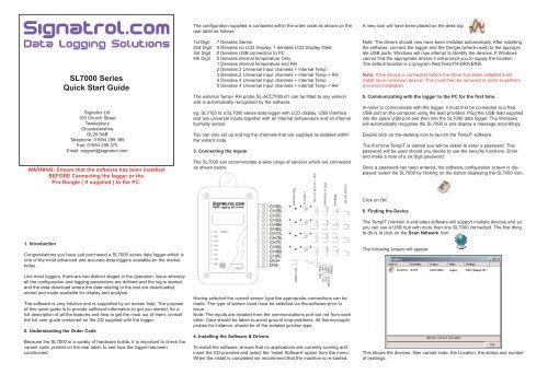
SL7000 Series<br />
Quick Start Guide<br />
Signatrol Ltd<br />
105 Church Street<br />
Tewkesbury<br />
Gloucestershire<br />
GL20 5AB<br />
Telephone: 01684 299 399<br />
Fax: 01684 299 375<br />
Email: support@signatrol.com<br />
WARNING: Ensure that the software has been installed<br />
BEFORE Connecting the logger or the<br />
Pro-Dongle ( If supplied ) to the PC.<br />
The configuration supplied is contained within the order code as shown on the<br />
rear label as follows:<br />
1st Digit<br />
2nd Digit<br />
3rd Digit<br />
4th Digit<br />
7 Denotes Series<br />
0 Denotes no LCD Display, 1 denotes LCD Display fitted<br />
0 Denotes USB connection to PC<br />
0 Denotes internal temperature Only<br />
1 Denotes internal temperature and RH<br />
2 Denotes 2 Universal Input channels + Internal Temp<br />
3 Denotes 2 Universal Input channels + Internal Temp + RH<br />
4 Denotes 4 Universal Input channels + Internal Temp<br />
5 Denotes 4 Universal Input channels + Internal Temp + RH<br />
The external Temp+ RH probe SL-ACC7000-01 can be fitted to any version<br />
and is automatically recognised by the software.<br />
eg. SL7103 Is a SL7000 series data logger with LCD display, USB interface<br />
and two universal inputs together with an internal temperature and an internal<br />
humidity sensor.<br />
You can only set up and log the channels that are supplied as detailed within<br />
the variant code.<br />
3. Connecting the inputs<br />
The SL7000 can accommodate a wide range of sensors which are connected<br />
as shown below.<br />
A new Icon will have been placed on the desk top.<br />
Note. The drivers should now have been installed automatically. After installing<br />
the software, connect the logger and the Dongle (where used) to the appropriate<br />
USB ports. Windows will now attempt to identify the devices. If Windows<br />
cannot find the appropriate drivers it will prompt you to supply the location .<br />
The default location is c:\program files\TempIT4\DRIVERS\.<br />
Note: If the device is connected before the driver has been installed it will<br />
install as an 'unknown device'. This must then be removed in order to perform<br />
a correct installation.<br />
5. Communicating with the logger to the PC for the first time.<br />
In order to communicate with the logger, it must first be connected to a free<br />
USB port on the computer using the lead provided. Plug the USB lead supplied<br />
into the spare USB port and then into the SL7000 data logger. The Windows<br />
will automatically recognise the SL7000 is and display a message accordingly.<br />
Double click on the desktop icon to launch the TempIT software.<br />
The first time TempIT is started you will be asked to enter a password. This<br />
password will be used should you decide to use the security functions. Enter<br />
and make a note of a six digit password.<br />
Once a password has been entered, the software configuration screen is displayed.<br />
select the SL7000 by clicking on the button displaying the SL7000 icon.<br />
1. Introduction<br />
Congratulations you have just purchased a SL7000 series data logger which is<br />
one of the most advanced and accurate data loggers available on the market<br />
today.<br />
Like most loggers, there are two distinct stages in the operation; Issue whereby<br />
all the configuration and logging parameters are defined and the log is started,<br />
and the data download where the data relating to the test are downloaded,<br />
stored and made available for display and analysis.<br />
The software is very intuitive and is supported by on screen help. The purpose<br />
of this quick guide is to provide sufficient information to get you started, for a<br />
full description of all the features and how to get the most out of them, consult<br />
the full user guide contained on the CD supplied with the logger.<br />
2. Understanding the Order Code<br />
Because the SL7000 in a variety of hardware builds, it is important to check the<br />
variant code, printed on the rear label, to see how the logger has been<br />
constructed.<br />
Having selected the correct sensor type the appropriate connections can be<br />
made. The type of sensor used must be selected via the software prior to<br />
issue.<br />
Note: The inputs are isolated from the communications port but not from each<br />
other. Care should be taken to avoid ground loop problems. All thermocouple<br />
probes for instance, should be of the isolated junction type.<br />
4. Installing the Software & Drivers<br />
To install the software, ensure that no applications are currently running and<br />
insert the CD provided and select the 'Install Software' option from the menu.<br />
When the install is completed we recommend that the machine is re-started.<br />
Click on OK.<br />
6. Finding the Device<br />
The TempIT (Version 4 and later) software will support multiple devices and so<br />
you can use a USB hub with more than one SL7000 connected. The first thing<br />
to do is to click on the Scan Network Icon:<br />
The following screen will appear<br />
This shows the devices, their variant code, the Location, the status and number<br />
of readings.
7. Configuring the logger<br />
Click on the Scan Network Icon and RIGHT CLICK on the device icon, and<br />
select 'Configure'<br />
A number of programming pages are presented as follows:<br />
The first screen, titled “General” sets parameters that are common to all<br />
channels. A brief summary of the parameters is listed below. Please consult the<br />
full manual supplied on CD for further information.<br />
Serial Number: Set at Factory and cannot be modified.<br />
Location: Enter here some meaningful description of up to 12 characters to<br />
enable easy identification.<br />
Data Type: Select one of the following Point, Average, Minimum, Maximum.<br />
This defines the value that well be stored to memory. Point means that every<br />
reading will be stored, Average means the average reading will be stored etc.<br />
Read Rate: This is the rate at which the inputs are measured. It also defines<br />
the Realtime display update rate. ( Default 4 seconds)<br />
Log Interval: This defines the time between stored values and is always a multiple<br />
of the Read Rate. (Default 60 seconds)<br />
Display Update: This defines the rate at which the LCD updates and scans<br />
when displaying multiple inputs. It also defines the flash rate of the LEDs The<br />
default is 4 seconds but setting this to a longer interval will improve battery life.<br />
Note: although the LCD is updated at this rate it will only have a new value<br />
after every new read i.e. if the read rate is set to 1 Minute, the LCD reading will<br />
only have a new value every minute even if the update rate is set to 4 seconds.<br />
First Reading Due: This is the current date and time as set on the PC or the<br />
date and time of the first reading when delayed start is active. This box shows<br />
'Trigger Start' if either magnetic or digital start is selected.<br />
Logger Full Expected: This box shows the date/time the logger is expected to<br />
be full when the 'Stop when Full' option on the right hand side of the page. It is<br />
meaningless when the @Wrap when full' option is selected.<br />
Battery Date: Allows you to enter the date the last time the battery was<br />
changed.<br />
Delayed Start: Select this when you want to start the logger at some fixed point<br />
in the future.<br />
Magnetic Start: Select this option when you want the logger to wait for an<br />
external magnet to start it logging.<br />
Digital Start: Select this option when you want the logger to wait for the exercising<br />
of an external digital signal ( Connected to the Dig in + and - Pins of the<br />
logger)<br />
Stop When Full: Select this option if you want the logger to stop logging when<br />
the memory is full.<br />
Wrap when full: Select this option if you want the logger to continuously log,<br />
overwriting the oldest data when the memory becomes full. Sometimes called<br />
FIFO.<br />
Default/Custom: There are two other buttons labelled Default and Custom.<br />
These set the effective memory size in readings per channel. Default sets the<br />
.<br />
memory size to the maximum available and custom allows a smaller maximum<br />
memory size to be set,.<br />
Input Setup<br />
Enabling Channels: Left hand tick boxes are used to select which channels are<br />
enabled for logging.<br />
Visual On: These buttons select which channels are displayed on the LCD<br />
Descriptor: Enter up to 12 characters to describe the input.<br />
Input: Temperature and humidity inputs are fixed type. For universal inputs<br />
select the input type.<br />
Linearisation: Many universal inputs have an associated linearisation that can<br />
be applied. The type of linearisation depends upon the type of sensor and is<br />
selected from the drop-down menu.<br />
Input Scaling: This is only active for the process inputs ( Current and Voltage)<br />
and enables the inputs to be scaled in engineering units. The units can be<br />
entered and will appear on printouts etc, this option only appears if the Icon<br />
box is set to 'None'. The Icon box enables an appropriate icon to be displayed<br />
on the LCD display, If selected other than 'None' this is also used for the 'units'<br />
field on graphs etc.<br />
Trigger setup: When enabled, a value can be entered, in engineering units, in<br />
the High or Low box (Or both). This parameter is used to start the logger when<br />
the input first passes this transition point. i.e. if enabled and Low was set to -30<br />
then when issued the logger will wait until a value of less that -30 was recorded<br />
on that channel before starting logging.<br />
Alarm Setup: When enabled, a high and/or low alarm can be set per channel<br />
together with a time function. The time is the number of consecutive reads<br />
where an alarm condition is identified before the alarm is recognised. When an<br />
alarm is recognised, the LED on that channel changes from flashing green to<br />
flashing red. All alarms are latching.<br />
Special Condition. There is a special condition if the logger is issued (Not using<br />
delayed or trigger start) and an alarm is immediately present. In this condition,<br />
the alarm is not recognised until the channel first passes into a non-alarmed<br />
state. This effectively arms the alarm which will then trigger the next time it<br />
goes into alarm.<br />
Frequency Inputs<br />
All units have a digital input facility that can be used to measure frequency. The<br />
digital can be either a Potential free contact, TTL, C MOS or Open Collector<br />
transistor.<br />
The logger stores the number of counts per log interval and this is stored on<br />
channel 9. Channel 9 cannot be displayed either on the LCD or on the LED<br />
indicators.<br />
The unit can measure frequencies up to 32 K Hz. For frequencies less that 50<br />
Hz to prevent contact bounce giving spurious readings, it is recommended that<br />
the internal filter is activated. This is achieved by repositioning an internal ling,<br />
see full manual for details.<br />
Manifest Text<br />
Here the Owners Name is displayed. This is entered the first time the logger is<br />
issued and cannot later be changed.<br />
It also provides for the entry of up to 256 characters of manifest text which<br />
form part of the record and are used to record useful information relating to the<br />
test run, shipment, application etc.<br />
Input Trim<br />
This requires a password entry. The password is entered the first time the logger<br />
is issued and cannot later be changed.<br />
The Input Trim enables custom calibrations to be entered in terms of offset and<br />
span corrections. This is not normally necessary and is normally only used in<br />
special applications. Consult the full manual for further details.<br />
8. Issuing the Logger<br />
When the configuration is complete click issue to 'issue' the logger.<br />
9. <strong>Download</strong>ing Data<br />
After a successful issue the logger will store data according to the parameters<br />
entered. At the end of the test the data are then downloaded to the computer<br />
for display and analysis.<br />
To download data:<br />
Click on the Scan network Icon, right click on the device and then select<br />
'<strong>Download</strong>'. The Data are then downloaded and immediately displayed on the<br />
screen in a graphical format. The data download can take up to 2 minutes for<br />
a full logger with the full memory.<br />
The buttons down the side of the graph are self explanatory and are used to<br />
manipulate the graph to the desired format. The cursor on the graph can be<br />
moved with the mouse and displays time/date and value in the text to the top<br />
of the graph.<br />
'Export Data' and 'Show Table' are features that are only available in<br />
TempIT-Pro<br />
Note: TempIT-Lite only allows up to two channels to be displayed on the graph<br />
at any one time with only two axes. For unlimited multiple traces and up to six<br />
different axes the upgrade to TempIT-Pro is required. Consult your supplier.<br />
10. Displaying a previously stored file<br />
Close down all the screens until you are left with the blank home page. Click<br />
on 'File' and 'Open Graph file' (Or alternatively the open file icon )<br />
A list of previously stored files will be presented. Double click on the file you<br />
wish to open.<br />
11. TempIT Pro-Upgrade<br />
To upgrade your software to TempIT-Pro contact your supplier. There are two<br />
ways the upgrade can be installed:<br />
1 An individual licence per machine (Lowers cost option for 1<br />
machine) whereby each machine has its own licence.<br />
2 A Pro Dongle which enables any PC with the dongle connected to<br />
operate as Pro. Lite (FOC) is installed on each machine and the dongle can be<br />
moved from machine to machine which automatically upgrades the Lite to Pro.<br />
12. Real time Mode<br />
This is used to display the channels selected for logging in real time electrical<br />
units and can be used as a check that everything has been wired correctly.<br />
WARNING: The displayed value is scanned initially within 1 second of the<br />
issue. The value is then updated at the selected read rate i.e if the read rate<br />
was set at 1 hour, it would be 1 hour before the realtime display would update.