Download - Lontek
Download - Lontek
Download - Lontek
- No tags were found...

You also want an ePaper? Increase the reach of your titles
YUMPU automatically turns print PDFs into web optimized ePapers that Google loves.
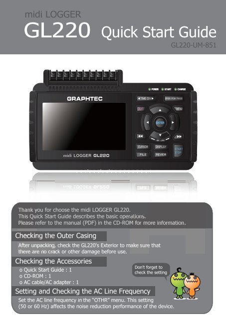
GL220 ContentsNomenclature............................................................................ 2Connection Procedures.............................................................. 3Precautions to Observe When Performing Measurement .............. 4Descriptions of the Control Panel Keys ....................................... 5Descriptions of the Menu Screens .............................................. 8Measurement Procedure............................................................ 91. Preparations : How to Make the Preparations Required for Data Capture.... 92. Setup : How to Make the Settings.................................................. 103. Data Capture : How to Capture Data .............................................. 134. Data Replay : How to Replay Captured Data ..................................... 14Convenient Functions................................................................ 15Trigger Functions to Control Data Capture Start/Stop Operations................. 15Span, Position and Trace Functions to Adjust the Waveform Display............. 17Specifications........................................................................... 18Standard Specifications ........................................................... 18External Input/Output Functions .............................................. 18Input Unit Specifications .......................................................... 19Installation Guide...................................................................... 201
GL220 NomenclatureTop PanelMonitorAnalog signal input terminalsControl panel keysPower switchOperation status LED-POWER-START-CHARGEAC adapter jackGND terminalConnecting the USBmemory devicePower jack for the humidity sensor(Humidity sensor is the option B-530)External input/output terminals-LOGIC/PULSE-EXT TRIG/SAMPLE-ALARMLogic alarm cable is required for connection(Cable is the option B-513)Bottom PanelBattery coverOne battery pack can be installed(Battery pack is the option B517)LabelUSB interface terminal2
GL220 Connection ProceduresConnecting the AC AdapterConnecting the Grounding CableGrounding cableConnect the output side of the AC adapter to theconnector indicated as "DC LINE" on the GL220.Use a flathead screwdriver to push the button above theground terminal while connecting the grounding cable to theGL220. Connect the other end of the cable to ground.Making Connections to the Analog Input TerminalsCH 1 2 3 4 5 6 7 8 9 10Direct voltage inputDirect current inputThermocouple input+Direct voltage-+Direct voltage-Shunt resistanceEx: for current in the 4 to 20 mArange, apply a resistance of 250 W(±0.1%) and perform measurementin the 1 to 5 V range.Note: Use B-551 (option)for this shunt resistance.+-Compensationcopper wireNote: Connect wires to the desired terminals according to the terminal numbers ontop of the terminal block.Making Connections to the External Input/Output TerminalsB-513Connection diagramOrange with red dotted line : 1Orange with black dotted line : 2Grey with red dotted line : 3Logic/pulseinputGrey with black dotted line : 4White with red dotted line : 1White with black dotted line : 2Alarm outputYellow with red dotted line : 3Yellow with black dotted line : 4Pink with red dotted line: Trigger input/external sampling inputPink with black dotted lineShieldedGND*B-513 (sold separately) cable is required for external input/output.(For logic/pulse input, alarm output, trigger input, external sampling input3
Precautions to Observe When Performing MeasurementMaximum input voltageIf a voltage exceeding the specified value is input, the semiconductor relay in theinput section will be damaged. Never input a voltage exceeding the specified valueeven for a moment.・Maximum input voltage : 60Vp-p・Maximum input voltage : 60Vp-pC・Withstand voltage : 350 Vp-p at 1 minute+ー+A・Maximum input voltage : 60Vp-pー +ー・Withstand voltage : 350 Vp-p at 1 minuteBWarming-upGL220 requests to have approximately 30 minutes warm-up in order to have thespecified performance.Unused channelsThe analog input section has high impedance.If it is open, measured value may vary due to noise.In such a case, set to "Off" unused channels in the AMP setting menu orshort the + and – terminals.Noise countermeasuresIf measured values fluctuate due to extraneous noise, conduct the followingcountermeasures.(Results may differ according to noise type.)Ex 1 : Connect the GL220's GND to ground.Ex 2 : Connect GL220's GND to measurement object's GND.Ex 3 : In the AMP settings menu, set filter to any setting other than "OFF".Ex 4 : Operate GL220 with batteries (Option: B-517).Ex 5: Set the sampling interval which enables GL220’s digital filter (see table below).4Number of MeasuringChannels*1 chahnnel or less2 chahnnels or less5 chahnnels or less10 chahnnels or lessAllowed Sampling Interval10 msec or slower**20 msec or slower**50 msec or slower**100 msec or slowerSampling Interval whichenables Digital Filter50 msec or slower125 msec or slower250 msec or slower500 msec or slower*Number of Measuring Channels” is the number of channels in whichinput settings are NOT set to “OFF”.**Temperature cannot be measured when the sampling interval is set to 10, 20, or 50 ms.
GL220 Descriptions of the Control Panel Keys(2) TIME/DIV(4) QUIT(1) SPAN/POSI/TRACE(3) MENU+ + ENTERPassword setting(5) DIRECTION KEYS(6) ENTER(7) FAST FORWARD (KEY LOCK)(12) CURSOR (ALARM CLEAR)(11) FILE(10) REVIEW(9) DISPLAY(8) START/STOP (USB DRIVE MODE)1. SPAN/POSI/TRACEThis key enables SPAN, POSITION, and TRACE settings to be made independently foreach channel. Each time this key is pressed, the display mode changes in the sequenceshown below. Use the and keys to select thechannel, and the and keys to change the setting values.MONITORSPANPOSITIONTRACEDisplays digital values (default).Used to change span settings (change the waveform amplitude).Used to change position settings (adjust the upper and lower valuesof the waveform).Used to change trace settings (set the waveform display to On or Off).Note: If the QUIT key is pressed when the GL220 is in the SPAN, POSITION,or TRACE mode, the display returns to MONITOR mode.2. TIME/DIVPress the TIME/DIV key to change the time axis display range on the waveform screen.5
3. MENUPress the MENU key to open a setup menu. Each time this key is pressed, the setup screentabs change in the sequence shown below.AMPDATATRIGUSEROTHR- AMP SettingsUsed to set the input, range, filter and other settings.- Data Capture SettingsUsed to set settings such as the sampling interval, data capturedestination, and calculations during data capture.- Trigger SettingsUsed to specify data capture start and stop conditions, and alarmconditions.- User SettingsUsed to set the names of the users of this device, and to changefrom one user to another.- Other SettingsUsed to set settings such as the screen brightness, backgroundcolor, and language.Settings arecomplete !4. QUIT (LOCAL)Press the QUIT key to cancel the settings and return them to their default status. If thedevice is in the Remote (Key Lock) status that the device is operated by the computer viathe interface,, press this key to return the device to the normal operating status (Local).5. Keys (DIRECTION KEYS)These keys are used to select menu setup items, to make span settings in the digital displayarea, to move the cursors during a data replay operation, and so forth.6. ENTERPress the ENTER key to enter the settings made in the setup menus, and to confirm yoursettings.7. Keys (KEY LOCK)These keys are used to move the cursor at high speed during a data replay operation, and tochange the operation mode in the file settings box. Hold down both keys simultaneously forat least two seconds to enable key lock status. To cancel key lock status, press them againfor at least two seconds.The key lock status can be confirmed by the status of the key lock lamp on the monitor.Note: Pressing these keys simultaneously with the key + ENTER + key enablespassword protection for the key lock operation.6
8. START/STOP (USB DRIVE MODE)Press the START/STOP key to perform start and stop of a data capture while the GL220 is inthe Free Running status. If this key is held down while the power to the GL220 is turned on,the GL220 goes into USB Drive Mode.Note: Refer to the User's Manual in the supplied CD-ROM for more information on the setting.9. DISPLAYPress the DISPLAY keyMany display modes areavailable !Waveform + DigitalExpanded WaveformWaveform + Digital : This is the default screen whenthe GL220 is turned on, and both waveforms and digitalvalues are displayed. The screen settings can also bechanged by using the SPAN/POSITION/TRACE key.Expanded Waveform : Displays waveforms only.Digital + CalcDigital + Calc : Displays large-size digital values andtwo types of calculation processing results. The calculationsettings are made in the "DATA" menu.Use the key or key to switch digital display modes.10. REVIEWPress the REVIEW key to replay captured data. If the GL220 is in the Free Running status,data files that have already been captured are replayed. If the GL220 is still capturing data,the data is replayed in a 2-screen format.Note: A data replay operation will not be performed if data has not been captured.11. FILEPress the FILE key to save data to the GL220's internal memory or a USB memory device.12. CURSOR (ALARM CLEAR)Press the CURSOR key to switch between the A and B cursors during a data replay operation.If the Alarm setting has been specified as "Alarm Hold", press this key to clear the alarm.The alarm settings are made in the "TRIG" menu.7
GL220 Descriptions of the Menu Screens4.Device access lamp1.Status message display area3.Status mark2.Time/DIV display area5.Remote lamp6.Key lock lamp7.Clock display8.AC/Battery status indicator18.Data capture bar9.Waveform operationdisplay area17.Scale upper limit10.Digital display area16.Waveform display area15.Scale lower limit11.Quick settings14.File name display area13.Pen display12.Alarm display area1.Status message display area : Displays the operating status.2.Time/DIV display area : Displays the current time scale.Status markFree Running status3.Status mark: Displays the status mark.Trigger waiting status4.Device access lamp : Turns red while the internal memory or USM memory is in access.Capture end statusTurns green when a USB memory device has been inserted.Capturing recording status5.Remote lamp: Displays the remote status. (Yellow = Remote status, white = Local status)6.Key lock lamp: Displays the key lock status. (Yellow = keys locked, white = not locked)Data replay status7.Clock display: Displays the current date and time.8.AC/Battery status indicator : Displays the following icons to indicate the operating status ofthe AC power and the battery. (see right figure)Note: Use this indicator as a guideline because remaining battery power is an estimate.AC/Battery IndicatorWhen the AC powersupply is being usedBattery power: 100 - 91%This indicator does not guarantee the operating time with battery.Battery power: 90 - 61%9.Waveform operation display area : Displays the mode selected by the SPAN/POSITION/TRACE key.10.Digital display area : Displays the input values for each channel. The and keys can be used toBattery power: 60 - 31%select the active channel (enlarged display). Moreover, the selected activechannel is displayed at the very top of the waveform display.Battery power: 30 -o 11%Battery power: 10% or less11.Quick settings : Displays items that can be easily set. The and keys can be used to makea Quick settings item active, and the and keys to change the values.12.Alarm display area : Displays the status of the alarm output. (Red = alarm generated, white = alarm not generated)13.Pen display: Displays the signal positions, trigger positions, and alarm ranges for each channel. (see right figure)14.File name display area : Displays the data capture file name during the data capture operation.When data is being replayed, the display position and cursorinformation is displayed here.Trigger positionAlarm range15.Scale lower limit: Displays the lower limit of the scale of the currently active channel.16.Waveform display area : The input signal waveforms are displayed here.Rising Outside17.Scale upper limit: Displays the upper limit of the scale of the currently active channel.trigger trigger theStop siderangetherange18.Data capture bar: Indicates the remaining capacity of the capture media during data capture.Start sideWhen data is being replayed, the display position and cursor information is displayed here.8
GL220 Measurement ProcedureIn this section we will provide a simple explanation of the data capture procedure:Preparations -> Setup -> Data Capture -> Data Replay.Voltage measurement is performed here.Purpose of data capture : To measure the temperature of the target objectsTemperature Range : T ThermocoupleVoltage range: 1VSampling interval : 1 secData save destination : Internal memory device1. Preparations : How to Make the Preparations Required for Data1.Connect Thermocouple to the CH 1 terminal (Temperature).2.Connect wire to the CH 2 terminal (Voltage).3.Connect the AC power supply.4.Turn on the power supply.Connect securely!2 134Measurementobject9
2. Setup: How to Make the SettingsMake the settings required for data capture. Here we will make only those settings that areminimum requirement. The other settings will be not changed from the factory default settings.Basic Setup Menu OperationThe key, the ENTER key, and the QUIT key are used to set the condition on the setup menu.Points to The current position of the cursor on the setup menu is displayed in green. Use the keysRemember ! to move the cursor. If you press the ENTER key at the cursor position, a selection menu or a boxof entering value for selected item is displayed. If you press the QUIT key, the screen closesand the settings are canceled.- Examples of selection menu operations (AMP screen)1. Use the keys to move thecursor to the Input parameter ofCH 1 and then press the ENTER key.2.A selection menu is displayed whenthe ENTER key is pressed. Use theand keys to select "TEMP."3. Press the ENTER key to confirm yourselection.(Note: Select "DC" for voltage measurement, and "Humidity" for humidity measurement.)TIME/DIVSPAN/POSI/TRACE1. Press the MENU key to display the setup menu screen.QUITENTERMENU2. Set Input to "TEMP" and Range to "TC-T" for CH1,and set Input to "DC" and Range to "1V" for CH2.(1) Move the cursor to CH1 "Input" and select "TEMP" and then move itto "Range" and select "TC-T."CURSORFILEDISPLAYREVIEWSTARTSTOPTIME/DIVQUITSPAN/POSI/TRACEMENU(2) In the same way, move the cursor to CH2 "Input" and select "DC" andthen move it to "Range" and select "1V."3. Select "Off" for all the other channels.(1)Using the procedure described above, select "Off" for CH 3 to CH 10.ENTERCURSORFILEDISPLAYREVIEWSTARTSTOP10
4. Press the MENU key and open the "DATA" menu.5. Set the sampling interval to "1s".Move the cursor to "Sampling" and then select "1s".6. Set the Data Capture Destination to "Internal memory".Here the "TEST" folder is created in the Internal memory device, and thendestination for the captured data is set to the TEST folder.(1) Move the cursor to the File Name parameter and then press the ENTER key.(2) Move the cursor to the item in the following screen, press the ENTER key.(3) The file settings box shown in the following screen opens. This box is used to specifyfile names for the GL220's internal memory and for the USB memory device.Note: is displayedwhen USB memory isinstalled.(4) Move the cursor to and then press the key.Press the key to move the cursor to and then press the ENTER key.Text input boxSelect the text type; delete; insert; confirmSelect the character(5) A text input box is displayed. Let's create a folder named "TEST".Input "TEST", move the cursor to , and then press the ENTER key to enter your setting.11
(6) Return to screen (2) and move the cursor to the icon to select the createdfolder and then press the ENTER key.(7) Move the cursor to and then press the ENTER key.When this setting has been completed, data will be captured and savedto the folder in the internal memory with an automatic file name.(8) Available space in specified memory device and time for data capture aredisplayed in the lower part of the Record Settings menu. The data capture timecan be checked.Minimum required setting for data capture is completed.12
3. Data Capture: How to Capture DataAll of setting for the data capture have been set, capturing data can be started now.During the data capture operation, let's also replay some data that was captured previously.1. Starting data capture(1) Press the START/STOP key.(2) A confirmation message is displayed.(3) Press the ENTER key to start data capture.2. Screen status during data captureOnce data capture has started, progress of data capture is shown. The displayedtime is counting up or down.capturing messageelapsed timeremaining time for data capture(The indication becomes ++++ when the data capture time is 9999 hours or more.)Points toRemember !Data can be replayed while being captured by pressing the REVIEW key. Datacan be replayed during the data capture operation from the beginning to thepoint that has been captured. During the replay, you can check arbitrary levelvalues and such by moving the cursor. You can return to the data capturescreen by pressing the REVIEW key again.REVIEW3. Stopping data capturePress the START/STOP key to end the data capture operation.(1) Press the START/STOP key.(2) A confirmation message is displayed. Press the ENTER key.(3) Data capture ends, and the GL220 goes into the Free Running status.The operation of data capture is completed.13
4. Data Replay : How to Replay Captured DataWhen data capture ends, data is automatically replayed. The automatically replayed datais the data captured to the internal memory which has been set as the data capture destination.Press the QUIT key to end the data replay operation.1.Selecting a file to replay(1) Press the REVIEW key.(2) Since the file you want to replay has the file name that was appended automaticallywhen the data was captured, move the cursor to the OK button and then pressthe ENTER key.(3) The Replay screen opens.2.Replay screen1.Scroll bar2. Level display area3. Quick settings4. Time display5. Cursor(1) Scroll bar : Displays the position within the whole data and the display width.(2) Level display area : Displays the levels of A and B cursors and the differencebetween the A and B values.(3) Quick settings : Use the keys to search the previous or next level.(Note: Make search settings in the menu.)(4) Time display : Displays the sampling interval and the time of the cursor.(5) Cursor : Displays the cursor. (Note: Press the CURSOR key to switchbetween A and B cursors.)Move the cursor using the keys or the keys.Desired level values and time can be checked by moving the cursor.Press the QUIT key to end the data replay operation.A confirmation message is displayed. Press the ENTER key.Data replay ends, and the GL220 goes into the Free Running status.Explanation of basic operation in the GL220 is completed.The GL220 has many other convenient functions. Please refer the next five pages for details.14
GL220 Convenient FunctionsThe GL220 has various functions that enable it to be used more effectively.The selected three functions are described with details in the following.Trigger Functions to Control Data Capture Start/Stop OperationsTrigger functions can be used to control the timing of the start of a data capture operation,and the timing of the end of a data capture operation.Points toRememberFor example...The trigger function performs operations such as the following:• Start data capture when the voltage exceeds 1 V• Stop data capture at 1:00 pm• Perform control via external inputHere data capture is started in the condition as "Start data capture when the CH 1temperature exceeds 20ºC".(1) Press the MENU key and open the "TRIG" menu.(2) Move the cursor to "Start Source" and select "Level".(3) Move the cursor to the "Mode" parameter for the CH 1, and then select "Hi".15
(4) Move the cursor to the "Level" parameter next to the "Mode" parameterand then press the ENTER key.(5) The input box shown in the following screen is displayed. Select "20".Use the and keys to move to the cursor to the second digit from the right,and the and keys to change the value. Press the ENTER key.Numerical value input boxLower and upper limit for setting.Waveform area for confirmationLower•Use the and keys to change the values.•Use the and keys to move the digit.•Use the ENTER key to enter the value.•Use the QUIT key to cancel the setting .(6) When the screen changes to the following screen, move the cursor tothebutton and then press the ENTER key.(7) The screen returns to the TRIG menu screen. Press the QUIT key to returnthe GL220 to the Free Running status.(8) Press the START/STOP key to start data capture. If the triggercondition has not been satisfied, the GL220 goes into the "Armed" statusas shown on the following screen.When the trigger condition has been satisfied, data capture starts and the"Memory Recording" is displayed. Elapsed time for data capture appears.16
Span, Position and Trace Functions to Adjust the Waveform DisplayThese functions enable to make adjustments in order to view individual channelsmore easily, and to delete waveforms that is not required to view in display.Points toRememberThe span, position and trace operations can be performed while the GL220is in the Free Running status, while it capturing data, and while it is replayingdata. The changes are applied to the displayed data only, the change is notaffected to the captured data.1.How to Make a Span settingThe Span parameter is used to adjust the amplitude of the input waveform.This setting is made in the aforementioned Free Running status.(1) Set the displayed span for CH 1 to 100ºC.(2) Press the SPAN/POSITION/TRACE key to select the SPAN mode.The currently selected mode(SPAN, POSITION or TRACE)can be checked by looking atthe "Waveform Operation Display Area".(3) Use the and keys to make CH 1 active (enlarged display).(4) Use the and keys to change the Span value. Here the value for span is set to 100ºC.When this setting has been changed, the waveform screen scale will be set to "+100.0 to +0.0".2.How to make a Position settingThe Position parameter is used to adjust the position of displayed waveform that is set bythe upper and lower values.(1) Press the SPAN/POSITION/TRACE key to select the POSITION mode.(2) Use the and keys to make CH 1 active (enlarged display).(3) Use the and keys to set the Position value to "+80ºC to -20ºC".When this setting has been changed, the waveform screen scale will be set to "+80ºC to -20ºC".3.How to make a Trace setting.The Trace parameter can be used to specify the selected waveform to be visible or invisible onthe display.(1) Press the SPAN/POSITION/TRACE key to select the TRACE mode.(2) Use the and keys to make CH 1 active (enlarged display).(3) Use the and keys to select Off.When this setting has been changed, the CH 1 waveform is not displayed.17
GL220 SpecificationsStandard SpecificationsItem DescriptionNumber of analog Channels 10External input and Trigger input and External sampling (1ch),output functions Logic input (4ch) or Pulse input (4ch), Alarm output (4ch)PC interfaceUSB (FullSpeed supported) provided as standard featuresBuilt-in memory Internal memory: Approx. 2GBdeviceUSB memory slot (FullSpeed supported) is provided as a standard featureSampling interval10ms/1ch MAX10*/20*/50*/100/125/200/250/500ms/1/2/5/10/20/30sec/1/2/5/10/20/30min/1hour/ExternalNote: Interval setting below 50 ms is available depending on the input settings andthe number of measurement channels.Back-up functions Setup parameters: EEPROM/Clock: Lithium batteryClock accuracy(ambient temperature 23°C) ±0.002% (approx. 50 seconds per month)Operating environment 0~45°C,5~85%RH (0 to 40°C when operated in batteries/15 to 35°C when battery is charging)Power supply AC adapter : 100 to 240 VAC, 50 to 60 HzDC input: 8.5 to 24 VDC(26.4 V max.)Battery pack (option) : 7.4 VDC (2200 mAh), 17Wh one pack requiredPower consumption AC power consumption (*when using the AC adapter provided as a standard accessory)No Condition Normal During recharging battery1 When the LCD is on 12VA 29VA2 When the screensaver is operating 11VA 28VADC current consumptionNo Condition Normal During recharging battery1When the LCD is on 0.18A 0.6A+24V2 When the screensaveris operating0.15A 0.57A3When the LCD is on 0.31A Recharging battery+12V When the screensaver4 is operating0.26A is not possible.5When the LCD is on 0.45A Recharging battery+8.5V When the screensaver6 is operating0.37A is not possible.*Normal condition: LCD brightness is set to MAX.External dimensions 194×117×42mmWeight520g (*Excluding the AC adapter and battery packs)Vibration-tested conditions Equivalent to automobile parts Type 1 classificationExternal Input/Output Functions18ItemInput specifications(pulse/logic,trigger/External sampling)Alarm outputspecificationsDescriptionMaximum input voltage : 0 to +24V(single-ended ground input)Input threshold voltage : approx. +2.5 VHysteresis : approx. 0.5 V (+2.5 V to +3 V)Output format : Open collector output (5 V, 10 k pull-up resistance)Refer to the User's Manual in the supplied CD-ROM for more information.
Input Unit SpecificationsItemDescriptionNumber of input channels M3 screw type, 10 channelsPhoto MOS relay scanning system,Methodall channels isolated,balanced inputMaximum sampling speed 10ms/1chMeasurementaccuracyMeasurementaccuracy *1(23°C±5°C)- When 30 minutesor more have elapsedafter power wasswitched on- Sampling 1s/10ch- Filter ON (10)- GND connectedA/D converterTemperature coefficientMaximum input voltageWithstand voltageCommon mode rejection ratioNoiseVoltage20m/50m/100m/200m/500m1/2/5/10/20/50/1-5V F.S.Temperature K、J、E、T、R、S、B、N、W(WRe5-26)Humidity 0 to 100% (voltage 0 V to 1 V scaling conversion) *with B-530 (option)Voltage±0.1% of F.S.ThermocoupleType Measurement Temperature Rang Measurement Accuracy0≤TS≤100 ±5.2˚CR/S100
GL220 APS Installation GuideThis guide describes how to install the GL220 application software.System RequirementsThis software can be installed on a PC which fulfills the followingconditions.OS : WindowsXP, WindowsVista, Windows 7CPU: Pentium4 1.7GHz or higherMemory : 256MB or more (512MB or more recommended)HDD: 200MB (1GB recommended) additional space required for installingthe application softwareDisplay : Resolution 1024 x 768 or higher, 65535 colors or above(16 Bit or higher)Others: CD-ROM drive (for installing from CD), USB port requiredTo Install the USB DriverTo connect this unit to a PC with the USB interface, a USB driver mustbe installed in the PC.A USB driver and the USB driver installation manual are stored on thesupplied CD-ROM. Install the USB driver according to this manual.(The manual location: D:\USB Driver\English\GL-USB-UM152.PDF)Note: D: drive name of CD-ROM. The letter of CD-ROM drive vary it with theCD-ROM drive of your PC.To Install GL220 Application SoftwareTo install the application software which sets and controls the GL220,follow the directions below.1. Insert the accompanying midi LOGGER GL220 CD-ROM in the PC'sCD drive. Select [Start] -> [Run] to open the [Run] window.2. In the [Open:] field, type in "D:\English\GL220_820APS\SETUP.EXE"and press [OK].3. The installer starts.("D:" represents the CD-ROM drive. Change this letter to the driveletter representing your CD-ROM drive, if necessary.)4. Follow all directions displayed by the installer to continue.Note: D: drive name of CD-ROM. The letter of CD-ROM drive vary it with theCD-ROM drive of your PC.20
Specifications are subject to change without notice.GL220 Quick Start Guide(GL220-UM-851)May 1, 20101st edition-01Publisher GRAPHTEC CORPORATION