Download - Lontek
Download - Lontek
Download - Lontek
- No tags were found...

Create successful ePaper yourself
Turn your PDF publications into a flip-book with our unique Google optimized e-Paper software.
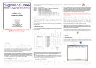
GL220 Connection ProceduresConnecting the AC AdapterConnecting the Grounding CableGrounding cableConnect the output side of the AC adapter to theconnector indicated as "DC LINE" on the GL220.Use a flathead screwdriver to push the button above theground terminal while connecting the grounding cable to theGL220. Connect the other end of the cable to ground.Making Connections to the Analog Input TerminalsCH 1 2 3 4 5 6 7 8 9 10Direct voltage inputDirect current inputThermocouple input+Direct voltage-+Direct voltage-Shunt resistanceEx: for current in the 4 to 20 mArange, apply a resistance of 250 W(±0.1%) and perform measurementin the 1 to 5 V range.Note: Use B-551 (option)for this shunt resistance.+-Compensationcopper wireNote: Connect wires to the desired terminals according to the terminal numbers ontop of the terminal block.Making Connections to the External Input/Output TerminalsB-513Connection diagramOrange with red dotted line : 1Orange with black dotted line : 2Grey with red dotted line : 3Logic/pulseinputGrey with black dotted line : 4White with red dotted line : 1White with black dotted line : 2Alarm outputYellow with red dotted line : 3Yellow with black dotted line : 4Pink with red dotted line: Trigger input/external sampling inputPink with black dotted lineShieldedGND*B-513 (sold separately) cable is required for external input/output.(For logic/pulse input, alarm output, trigger input, external sampling input3