Tow Winch Load Control - Towmasters: the Master of Towing ...
Tow Winch Load Control - Towmasters: the Master of Towing ...
Tow Winch Load Control - Towmasters: the Master of Towing ...

You also want an ePaper? Increase the reach of your titles
YUMPU automatically turns print PDFs into web optimized ePapers that Google loves.
Amsterdam, The Ne<strong>the</strong>rlands<br />
Organised by <strong>the</strong> ABR Company Ltd<br />
Day<br />
Paper No.<br />
2<br />
2<br />
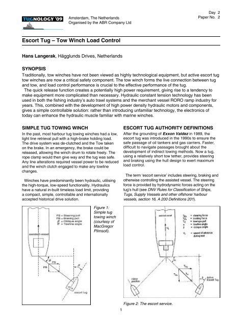
Escort Tug – <strong>Tow</strong> <strong>Winch</strong> <strong>Load</strong> <strong>Control</strong><br />
Hans Langerak, Hägglunds Drives, Ne<strong>the</strong>rlands<br />
SYNOPSIS<br />
Traditionally, tow winches have not been viewed as highly technological equipment, but active escort tug<br />
tow winches are now a critical safety component. The tow winch forms <strong>the</strong> live connection between tug<br />
and tow, and load control performance is crucial to <strong>the</strong> effective performance <strong>of</strong> <strong>the</strong> tug.<br />
The quick release function creates a potentially high power requirement, giving rise to a tendency to<br />
make equipment more complicated than necessary. Hydraulic constant tension technology has been<br />
used in both <strong>the</strong> fi shing industry’s auto trawl systems and <strong>the</strong> merchant vessel RORO ramp industry for<br />
years. This, combined with <strong>the</strong> development <strong>of</strong> high power density hydraulic motors and components,<br />
gives a simple controllable solution: ra<strong>the</strong>r than introducing unfamiliar technology, <strong>the</strong> electronics <strong>of</strong><br />
today can enhance <strong>the</strong> hydraulic muscle familiar with marine winches.<br />
SIMPLE TUG TOWING WINCH<br />
In <strong>the</strong> past, most harbour tug towing winches had a low,<br />
light line retrieval pull with a high-brake holding load.<br />
The drive system was de-clutched and <strong>the</strong> <strong>Tow</strong> taken<br />
on <strong>the</strong> brake. In an emergency, <strong>the</strong> brake could be<br />
released, allowing <strong>the</strong> winch drum to rotate freely. The<br />
rope clamp would <strong>the</strong>n give way and <strong>the</strong> tug was safe.<br />
Any line alterations required vessel power to be reduced<br />
and <strong>the</strong> winch clutch engaged to make any towline<br />
changes.<br />
<strong>Winch</strong>es have predominantly been hydraulic, utilising<br />
<strong>the</strong> high-torque, low-speed functionality. Hydraulics<br />
have a natural in-built timeless load limit, providing<br />
a compact, simple, controllable and internationally<br />
accepted historical drive solution.<br />
ESCORT TUG AUTHORITY DEFINITIONS<br />
After <strong>the</strong> grounding <strong>of</strong> Exxon Valdez in 1989, <strong>the</strong><br />
escort tug was introduced in <strong>the</strong> 1990s to ensure <strong>the</strong><br />
safe passage <strong>of</strong> oil tankers and gas carriers. Faster,<br />
diffi cult to navigate passages brought about <strong>the</strong><br />
development <strong>of</strong> indirect towing methods. Now a tug,<br />
using a relatively short tow te<strong>the</strong>r, provides steering<br />
and braking using <strong>the</strong> hull design to exert maximum<br />
load control.<br />
The term ‘escort service’ includes steering, braking and<br />
o<strong>the</strong>rwise controlling <strong>the</strong> assisted vessel. The steering<br />
force is provided by hydrodynamic forces acting on <strong>the</strong><br />
tug’s hull (see DNV Rules for Classification <strong>of</strong> Ships,<br />
Tugs, Supply Vessels and o<strong>the</strong>r <strong>of</strong>fshore/ harbour<br />
vessels, section 16, A 200 Definitions 201).<br />
Figure 1:<br />
Simple tug<br />
towing winch<br />
(courtesy <strong>of</strong><br />
MacGregor<br />
Plimsoll).<br />
Figure 2: The escort service.<br />
1
Figure 4:<br />
Simple<br />
load-control<br />
hydraulic<br />
circuit.<br />
Figure 3: Typical escort tug operational attitude<br />
(courtesy <strong>of</strong> Robert Allen Associates).<br />
The tug design uses <strong>the</strong> ship’s propulsion in<br />
conjunction with <strong>the</strong> keel kedge to provide <strong>the</strong><br />
manoeuvring force through <strong>the</strong> tow line and winch.<br />
To protect <strong>the</strong> escort tug from being overturned, <strong>the</strong><br />
winch must be live and use a safe load control system.<br />
Certifying authorities have had to redefine <strong>the</strong> tow winch<br />
specifications to take into account <strong>the</strong> dangers <strong>of</strong> this<br />
operation.<br />
• The towing winch has to have a load-reducing<br />
system in order to prevent overload caused by<br />
dynamic oscillation in <strong>the</strong> towing line;<br />
• Normal escort operation is not to be based on <strong>the</strong><br />
use <strong>of</strong> brakes on <strong>the</strong> towing winch;<br />
• The towing winch must be able to pay out towing<br />
line if <strong>the</strong> pull exceeds 50 per cent <strong>of</strong> <strong>the</strong> breaking<br />
strength <strong>of</strong> <strong>the</strong> towing line.<br />
This type <strong>of</strong> performance is not uncommon in<br />
hydraulics within <strong>the</strong> marine industry.<br />
SIMPLE HYDRAULIC LOAD CONTROL<br />
By setting a limit on <strong>the</strong> pressure in <strong>the</strong> hydraulic<br />
system, a load limit is set.<br />
• Power = Force x Speed;<br />
• Hydraulic pressure is Force;<br />
• Flow is Speed;<br />
• Pressure is limited by relief valve A;<br />
• With a pulling force on <strong>the</strong> towline lower than <strong>the</strong><br />
setting <strong>of</strong> A, <strong>the</strong> towline will be pulled in at a speed<br />
in relation to <strong>the</strong> design flow;<br />
• A pulling force on <strong>the</strong> towline higher than <strong>the</strong> setting<br />
<strong>of</strong> A will pull <strong>the</strong> towline out at whatever speed is<br />
required to limit <strong>the</strong> load.<br />
This load-control function provides a constant line<br />
tension.<br />
2<br />
LOAD LIMIT AND CONSTANT TENSION<br />
APPLICATIONS<br />
For more than 50 years this simple process has been<br />
used in various applications:<br />
• Mooring winches for merchant and <strong>of</strong>fshore;<br />
• Autotrawl for fishing trawlers;<br />
• RORO winches for merchant <strong>of</strong>floading.<br />
FISHING AUTOTRAWL TENSION CONTROL<br />
The traditional fishing method was to shoot <strong>the</strong> net,<br />
put on <strong>the</strong> brakes and tow. Fish swim horizontally so,<br />
as <strong>the</strong> vessel pitched on <strong>the</strong> waves, fish were missed.<br />
The most expensive fish swim near <strong>the</strong> sea bottom;<br />
if <strong>the</strong> net became caught, <strong>the</strong> only option was for <strong>the</strong><br />
wire to break.<br />
<strong>Tow</strong>ing <strong>the</strong> net live on <strong>the</strong> winch motors, ra<strong>the</strong>r than<br />
<strong>the</strong> brakes, produced a revelation in stern trawling. A<br />
pressure could be set that would hold and tow <strong>the</strong> net.<br />
As <strong>the</strong> vessel pitched on a wave, <strong>the</strong> additional force<br />
would allow <strong>the</strong> wire to be pulled out. As <strong>the</strong> vessel<br />
came down on <strong>the</strong> wave, <strong>the</strong> wire would be pulled back<br />
in. <strong>Tow</strong>ing along <strong>the</strong> bottom, if <strong>the</strong> net became caught,<br />
<strong>the</strong> wire would be pulled out. The vessel bollard pull<br />
would be reduced and <strong>the</strong> winches would slowly pull <strong>the</strong><br />
vessel towards <strong>the</strong> net and, as <strong>the</strong> angle changed, <strong>the</strong><br />
net would become free.<br />
With regard to stern trawling, fishing vessels are fully<br />
automated, with links to depth sounders, wire set length<br />
automatic control, net mouth opening measurements<br />
and logging functions. All control <strong>the</strong> winches by using<br />
simple pressure control interfaced with electronics.
TELECOMMUNICATIONS CABLE BURIAL<br />
• A plough is towed by <strong>the</strong> vessel;<br />
• The tow rope force is held against <strong>the</strong> motor and<br />
relief valve;<br />
• If <strong>the</strong> plough becomes stuck <strong>the</strong> tow rope will be<br />
pulled out, preventing damage to <strong>the</strong> plough;<br />
• Constant tension is not used, only load limit.<br />
Figure 7: Telecommunications cable laying system<br />
(courtesy <strong>of</strong> SMD).<br />
Figure 5: Autotrawl.<br />
RORO JUMBO RAMP CONSTANT TENSION<br />
• A 200-tonne ramp can cause quay damage;<br />
• <strong>Winch</strong>es with constant tension hold back 190 <strong>of</strong> <strong>the</strong><br />
200 tonnes;<br />
• As <strong>the</strong> vessel is unloaded and <strong>the</strong> tide changes, <strong>the</strong><br />
position compensates automatically;<br />
• Highly technical efficiency is needed for accurate<br />
loads.<br />
LOW TENSION<br />
Figure 8: Sub-sea plough towing arrangement.<br />
INERTIA AND LOAD LIMIT<br />
• Drive system inertia is important to prevent<br />
expensive damage to <strong>the</strong> laying equipment at <strong>the</strong><br />
point <strong>of</strong> overload.<br />
Figure 9: Inertia comparison chart. See end <strong>of</strong> paper.<br />
Figure 6: RORO jumbo ramps.<br />
3<br />
TYPICAL TUG TENSION CONTROL WINCH<br />
The JonRie 250 series direct-drive hydraulic tension<br />
control winch gives <strong>the</strong> captain <strong>the</strong> facility to set <strong>the</strong><br />
maximum tension.
• Valve C is a remote adjustable control;<br />
• The pressure compensating piston pump Pm will<br />
provide pressure up to <strong>the</strong> pressure setting <strong>of</strong> C;<br />
• Valve D gives <strong>the</strong> difference between Pm heave<br />
in pressure and relief valve A pull-out load pressure;<br />
• Valve C can be used to adjust towline length in<br />
a controlled manner by increasing <strong>the</strong> pressure<br />
capability;<br />
• <strong>Load</strong> release can be achieved with valve C;<br />
• D can be an adjustable valve to control <strong>the</strong> deadband;<br />
• Using electronics to interface with <strong>the</strong>se valves<br />
gives a fully flexible load control system.<br />
Figure 10: Escort tug winch (courtesy <strong>of</strong> JonRie).<br />
TENSION CONTROL WITH DEADBAND<br />
In some applications, it can be preferable to be able<br />
to set a different heaving-in load to <strong>the</strong> pull-out load<br />
limit. This is called deadband. It can also reduce power<br />
consumption and heat.<br />
EQUIPMENT SELECTION<br />
Using this technique gives a completely new load<br />
function to <strong>the</strong> winch and drive system. The drive is now<br />
<strong>the</strong> connection between <strong>the</strong> tug engines and <strong>the</strong> load.<br />
The power that can be engaged can be high.<br />
• The winch drive is now <strong>the</strong> connection between <strong>the</strong><br />
full power <strong>of</strong> <strong>the</strong> tug engines and <strong>the</strong> vessel on tow;<br />
• For <strong>the</strong> emergency release high speed and<br />
potential high power is required;<br />
• Deck space is at a premium;<br />
• Specifications and conditions can be variable.<br />
HYDRAULIC MOTORS<br />
These come in various types and sizes and, generally,<br />
have been quite low powered. This is because <strong>the</strong><br />
market for hydraulics is generally low speed. Power is<br />
pressure multiplied by flow and <strong>the</strong> pressure is generally<br />
dictated by pipework specification. A motor that is<br />
designed to get a high flow through, which is <strong>the</strong> o<strong>the</strong>r<br />
power element to pressure, increases <strong>the</strong> physical size<br />
and <strong>the</strong>refore <strong>the</strong> cost.<br />
Figure 12: Power-to-weight ratio.<br />
Figure 11: Simple load control circuit with deadband.<br />
4<br />
The development <strong>of</strong> radial piston cam curve motors<br />
for industrial drives has created a compact high power<br />
motor which uses four-port connection block technology,<br />
achieving a power-to-weight ratio <strong>of</strong> 3kW per kilogram.
Figure 13: Hägglunds compact motor.<br />
• Compact is a radial piston cam ring motor with a<br />
rotating hollow shaft;<br />
Figure 17: LNG active escort tug winch.<br />
• Introduced: 1994;<br />
• Max torque: 73,000 nm;<br />
• Speed range: up to 400 rev/min;<br />
• Displacement: 1.2-13.2 lit/rev (26.4 lit/rev in<br />
tandem);<br />
• The motor has an efficient design for high power<br />
constant tension drive. The port plate design allows<br />
for high acceleration load release functionality.<br />
Figure 14: Hägglunds compact motor data. See end <strong>of</strong><br />
paper.<br />
• CA 100 at 200 rev/min has a flow capacity <strong>of</strong> 1,250<br />
lpm;<br />
• Uses four ports;<br />
• 15-bar charge and 12-bar pressure drop;<br />
• Power approximately 650kW continuous;<br />
• Compact valves 1,000 lpm 350-bar.<br />
Special valves are normally needed to handle <strong>the</strong>se<br />
sorts <strong>of</strong> flow level. To complement <strong>the</strong> motors a range<br />
<strong>of</strong> standard flow and pressure control valves have been<br />
designed.<br />
Figure 15: Hägglunds compact valves. See end <strong>of</strong><br />
paper.<br />
LNG ACTIVE ESCORT TUG<br />
There is a system where, if <strong>the</strong> ship being towed<br />
creates overload, <strong>the</strong> VCTCA 1000 valve will open and<br />
<strong>the</strong> pump flow will be fed into <strong>the</strong> cooling loop.<br />
Figure 16: LNG active escort tug hydraulic system. See<br />
end <strong>of</strong> paper.<br />
5<br />
Figure 18: LNG active escort tug Romulo.<br />
Here <strong>the</strong> vessel sets at a different angle, allowing<br />
maximum operation loads closer to <strong>the</strong> safety limits.<br />
TRADITIONAL DRIVES<br />
The traditional high-torque load-control drive system<br />
has always been used in hydraulics. An increase<br />
in available information and greater flexibility has<br />
promoted a move towards electric drives. The Compact<br />
high-flow design gives hydraulic drive systems greater<br />
application acceptability. The use <strong>of</strong> electronics to<br />
enhance <strong>the</strong> hydraulic strength and flexibility is a<br />
simpler solution.<br />
Hydraulics is <strong>the</strong> muscle and electronics is <strong>the</strong> brain.<br />
Let us not confuse <strong>the</strong> issues.
Figure 18: Simplicity.<br />
HYDRAULIC MARINE TRADITIONS<br />
• Changing to complex drive systems to suit trends<br />
may not be necessary;<br />
• The drive muscle exists;<br />
• Environmentally acceptable fluids are available;<br />
• Hydraulics can provide simple regenerative power;<br />
• Using <strong>the</strong> latest electronics to enhance a traditional<br />
Marine Drive System could be more pr<strong>of</strong>itable.<br />
Figure 9: Inertia comparison chart.<br />
6
Figure 14: Hägglunds compact motor data.<br />
Figure 15: Hägglunds compact valves.<br />
7
Figure 16: LNG active escort tug hydraulic system.<br />
8