Aikido All in One.pdf - Tube CAD Journal
Aikido All in One.pdf - Tube CAD Journal
Aikido All in One.pdf - Tube CAD Journal
You also want an ePaper? Increase the reach of your titles
YUMPU automatically turns print PDFs into web optimized ePapers that Google loves.
GlassWare Audio Design<br />
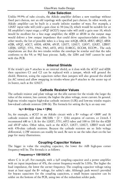
<strong>Tube</strong> Selection<br />
Unlike 99.9% of tube circuits, the <strong>Aikido</strong> amplifier def<strong>in</strong>es a new topology without<br />
fixed part choices, not an old topology with specified part choices. In other words, an<br />
<strong>Aikido</strong> amplifier can be built <strong>in</strong> a nearly <strong>in</strong>f<strong>in</strong>ite number of ways. For example, a<br />
12AX7 <strong>in</strong>put tube will yield a ga<strong>in</strong> close to 50 (mu/2), which would be suitable for an<br />
SE amplifier’s <strong>in</strong>put stage; a 6FQ7 (6CG7) <strong>in</strong>put tube will yield a ga<strong>in</strong> near 10, which<br />
would be excellent for a l<strong>in</strong>e stage amplifier; the 6DJ8 or 6H30 <strong>in</strong> the output stage<br />
would deliver a low output impedance that could drive capacitance-laden cables. In<br />
other words, the list of possible tubes is a long one: 6AQ8, 6BC8, 6BK7, 6BQ7, 6BS8,<br />
6DJ8, 6FQ7, 6GC7, 6H30, 6KN8, 6N1P, 12AT7, 12AU7, 12AV7, 12AX7, 12BH7,<br />
12DJ8, 12FQ7, 5751, 5963, 5965, 6072, 6922, E188CC, ECC88, ECC99… The only<br />
stipulations are that the two triodes with<strong>in</strong> the envelope be similar and that the tube<br />
conforms to the 9A or 9AJ base p<strong>in</strong>-out. Sadly, the 12B4 and 5687 cannot be used<br />
with this PCB.<br />
Internal Shields<br />
If the triode’s p<strong>in</strong> 9 attaches to an <strong>in</strong>ternal shield, as it does with the 6CG7 and 6DJ8,<br />
then capacitors C1 and C2 can be replaced with a jumper, which will ground the<br />
shield. However, us<strong>in</strong>g the capacitors rather than jumpers will also ground the shield<br />
(<strong>in</strong> AC terms) and allow swapp<strong>in</strong>g <strong>in</strong> triodes whose p<strong>in</strong>-9 attaches to the center tap of<br />
its heater, such as the 12AU7.<br />
Cathode Resistor Values<br />
The cathode resistor and plate voltage set the idle current for the triode: the larger the<br />
value of the resistor, less current; the higher the plate voltage, more current. In general,<br />
high-mu triodes require high-value cathode resistors (1-2K) and low-mu triodes require<br />
low-valued cathode resistors (100-1k). The formula for sett<strong>in</strong>g the Iq is an easy one:<br />
Iq = B+/2(rp + [mu + 1]Rk)<br />
So, for example, a 6CG7 <strong>in</strong> an <strong>Aikido</strong> circuit with a B+ voltage of +300V and 1k<br />
cathode resistors will draw 300/2(8k + [2 + 1]1k) amperes of current, or 2.6mA. I<br />
recommend 680 to 1.1k for the 12AX7, 5751, 6072 tubes and 100 to 330 for the 6DJ8<br />
and 6N1P tubes. Other tubes, such as the 6CG7, 12AT7, 12AU7, 12BH7 work well<br />
with 470-ohm cathode resistors. Because the cathode resistors see so little voltage<br />
differential, 1/2W resistors can readily be used. Be sure to see the tube chart on the last<br />
page for many illustrations.<br />
Coupl<strong>in</strong>g-Capacitor Values<br />
The bigger <strong>in</strong> value the coupl<strong>in</strong>g capacitor, the lower the -3dB high-pass corner<br />
frequency will be. The formula is as follows:<br />
Frequency = 159155/C/R<br />
where C is <strong>in</strong> µF. For example, with a 1µF coupl<strong>in</strong>g capacitor and a power amplifier<br />
with an <strong>in</strong>put impedance of 47k, the corner frequency would be 3.5Hz. The higher the<br />
load impedance, the lower the corner frequency. The coupl<strong>in</strong>g capacitor voltage rat<strong>in</strong>g<br />
must at least equal the B+ voltage, for safety’s sake. Although pads weren’t provided<br />
for bypass capacitors for the coupl<strong>in</strong>g capacitors, a small bypass capacitor can be<br />
solder on the bottom of the PCB, us<strong>in</strong>g two of the redundant solder pads.


