

Aikido All in One.pdf - Tube CAD Journal
Aikido All in One.pdf - Tube CAD Journal
Aikido All in One.pdf - Tube CAD Journal

You also want an ePaper? Increase the reach of your titles
YUMPU automatically turns print PDFs into web optimized ePapers that Google loves.
GlassWare Audio Design<br />
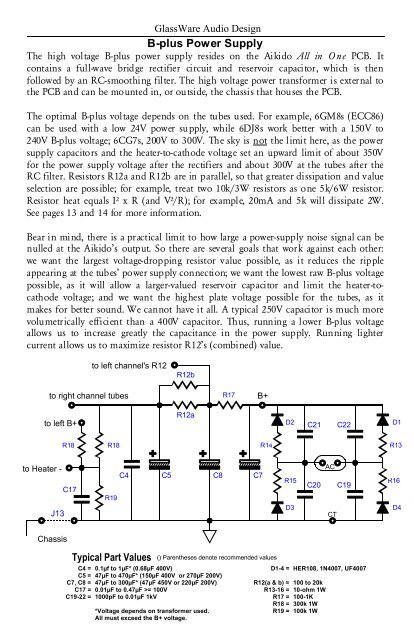
B-plus Power Supply<br />
The high voltage B-plus power supply resides on the <strong>Aikido</strong> <strong>All</strong> <strong>in</strong> O ne PCB. It<br />
conta<strong>in</strong>s a full-wave bridge rectifier circuit and reservoir capacitor, which is then<br />
followed by an RC-smooth<strong>in</strong>g filter. The high voltage power transformer is external to<br />
the PCB and can be mounted <strong>in</strong>, or outside, the chassis that houses the PCB.<br />
The optimal B-plus voltage depends on the tubes used. For example, 6GM8s (ECC86)<br />
can be used with a low 24V power supply, while 6DJ8s work better with a 150V to<br />
240V B-plus voltage; 6CG7s, 200V to 300V. The sky is not the limit here, as the power<br />
supply capacitors and the heater-to-cathode voltage set an upward limit of about 350V<br />
for the power supply voltage after the rectifiers and about 300V at the tubes after the<br />
RC filter. Resistors R12a and R12b are <strong>in</strong> parallel, so that greater dissipation and value<br />
selection are possible; for example, treat two 10k/3W resistors as one 5k/6W resistor.<br />
Resistor heat equals I² x R (and V²/R); for example, 20mA and 5k will dissipate 2W.<br />
See pages 13 and 14 for more <strong>in</strong>formation.<br />
Bear <strong>in</strong> m<strong>in</strong>d, there is a practical limit to how large a power-supply noise signal can be<br />
nulled at the <strong>Aikido</strong>’s output. So there are several goals that work aga<strong>in</strong>st each other:<br />
we want the largest voltage-dropp<strong>in</strong>g resistor value possible, as it reduces the ripple<br />
appear<strong>in</strong>g at the tubes’ power supply connection; we want the lowest raw B-plus voltage<br />
possible, as it will allow a larger-valued reservoir capacitor and limit the heater-tocathode<br />
voltage; and we want the highest plate voltage possible for the tubes, as it<br />
makes for better sound. We cannot have it all. A typical 250V capacitor is much more<br />
volumetrically efficient than a 400V capacitor. Thus, runn<strong>in</strong>g a lower B-plus voltage<br />
allows us to <strong>in</strong>crease greatly the capacitance <strong>in</strong> the power supply. Runn<strong>in</strong>g lighter<br />
current allows us to maximize resistor R12’s (comb<strong>in</strong>ed) value.<br />
to left channel's R12<br />
R12b<br />
to right channel tubes<br />
R17<br />
B+<br />
to left B+<br />
R12a<br />
D2<br />
C21<br />
C22<br />
D1<br />
R18<br />
R18<br />
R14<br />
R13<br />
to Heater -<br />
C17<br />
R19<br />
C4<br />
C5<br />
C8<br />
C7<br />
R15<br />
C20<br />
AC<br />
C19<br />
R16<br />
J13<br />
D3<br />
CT<br />
D4<br />
Chassis<br />
Typical Part Values<br />
C4 = 0.1µf to 1µF* (0.68µF 400V)<br />
C5 = 47µF to 470µF* (150µF 400V or 270µF 200V)<br />
C7, C8 = 47µF to 300µF* (47µF 450V or 220µF 200V)<br />
C17 = 0.01µF to 0.47µF >= 100V<br />
C19-22 = 1000pF to 0.01µF 1kV<br />
*Voltage depends on transformer used.<br />
<strong>All</strong> must exceed the B+ voltage.<br />
() Parentheses denote recommended values<br />
D1-4 = HER108, 1N4007, UF4007<br />
R12(a & b) = 100 to 20k<br />
R13-16 = 10-ohm 1W<br />
R17 = 100-1K<br />
R18 = 300k 1W<br />
R19 = 100k 1W


