
Create successful ePaper yourself
Turn your PDF publications into a flip-book with our unique Google optimized e-Paper software.
Reference Manual<br />
P <strong>DX</strong> <strong>3312</strong> D<br />
Dual AES & Analog Audio Demultiplexer<br />
Series 3000<br />
MiniModules<br />
© <strong>LYNX</strong> <strong>Technik</strong> <strong>AG</strong><br />
Brunnenweg 3<br />
64331 Weiterstadt<br />
Germany<br />
www.lynx-technik.com
Reference Manual P <strong>DX</strong> <strong>3312</strong> D Version1.0<br />
Page 2<br />
Information in this document is subject to change without<br />
notice. No part of this document may be reproduced or<br />
transmitted in any form or by any means, electronic or<br />
mechanical for any purpose, without express written permission<br />
of <strong>LYNX</strong> <strong>Technik</strong> <strong>AG</strong>.<br />
<strong>LYNX</strong> <strong>Technik</strong> <strong>AG</strong> may have patents, patent applications,<br />
trademarks, copyrights or other intellectual property rights<br />
covering the subject matter in this document. Except as<br />
expressly written by <strong>LYNX</strong> <strong>Technik</strong> <strong>AG</strong>, the furnishing of this<br />
document does not give you any license to patents,<br />
trademarks, copyrights or other intellectual property of <strong>LYNX</strong><br />
<strong>Technik</strong> <strong>AG</strong> or any of its affiliates.<br />
© <strong>LYNX</strong> <strong>Technik</strong> <strong>AG</strong> 2002 all rights reserved
Warranty<br />
Reference Manual P <strong>DX</strong> <strong>3312</strong> D Version1.0<br />
<strong>LYNX</strong> <strong>Technik</strong> <strong>AG</strong> warrants that the product will be free from<br />
defects in materials and workmanship for a period of two (2)<br />
years from the date of shipment. If this product proves defective<br />
during the warranty period, <strong>LYNX</strong> <strong>Technik</strong> <strong>AG</strong> at its option will<br />
either repair the defective product without charge for parts and<br />
labor, or will provide a replacement in exchange for the<br />
defective product.<br />
In order to obtain service under this warranty, customer must<br />
notify <strong>LYNX</strong> <strong>Technik</strong> of the defect before expiration of the<br />
warranty period and make suitable arrangements for the<br />
performance of service. Customer shall be responsible for<br />
packaging and shipping the defective product to the service<br />
center designated by <strong>LYNX</strong> <strong>Technik</strong>, with shipping charges<br />
prepaid. <strong>LYNX</strong> <strong>Technik</strong> shall pay for the return of the product to<br />
the customer if the shipment is within the country which the <strong>LYNX</strong><br />
<strong>Technik</strong> service center is located. Customer shall be responsible<br />
for payment of all shipping charges, duties, taxes and any other<br />
charges for products returned to any other locations.<br />
This warranty shall not apply to any defect, failure, or damage<br />
caused by improper use or improper or inadequate<br />
maintenance and care. <strong>LYNX</strong> <strong>Technik</strong> shall not be obligated to<br />
furnish service under this warranty a) to repair damage resulting<br />
from attempts by personnel other than <strong>LYNX</strong> <strong>Technik</strong><br />
representatives to install, repair or service the product; b) to<br />
repair damage resulting from improper use or connection to<br />
incompatible equipment; c) to repair any damage or<br />
malfunction caused by the use of non <strong>LYNX</strong> <strong>Technik</strong> supplies; or<br />
d) to service a product which has been modified or integrated<br />
with other products when the effect of such modification or<br />
integration increases the time or difficulty servicing the product.<br />
THIS WARRANTY IS GIVEN BY <strong>LYNX</strong> TECHNIK WITH RESPECT TO THIS<br />
PRODUCT IN LIEU OF ANY OTHER WARRANTIES, EXPRESS OR<br />
IMPLIED. <strong>LYNX</strong> TECHNIK AND ITS VENDORS DISCLAIM ANY IMPLIED<br />
WARRANTIES OF MERCHANTABILITY OR FITNESS FOR A PARTICULAR<br />
PURPOSE. <strong>LYNX</strong> TECHNIK`S RESPONISIBILITY TO REPAIR AND<br />
REPLACE DEFECTIVE PRODUCTS IS THE SOLE AND EXCLUSIVE<br />
REMEDY PROVIDED TO THE CUSTOMER FOR BREACH OF THIS<br />
WARRANTY. <strong>LYNX</strong> TECHNIK AND ITS VENDORS WILL NOT BE LIABLE<br />
FOR ANY INDIRECT, SPECIAL, INCIDENTAL, OR CONSEQUENTAL<br />
DAM<strong>AG</strong>ES IRRESPECTIVE OF WHETHER <strong>LYNX</strong> TECHNIK OR THE<br />
VENDOR HAS ADVANCE NOTICE OF THE POSSIBILITY OF SUCH<br />
DAM<strong>AG</strong>ES.<br />
Page 3
Reference Manual P <strong>DX</strong> <strong>3312</strong> D Version1.0<br />
Regulatory information<br />
Page 4<br />
Europe<br />
Declaration of Conformity<br />
USA<br />
We <strong>LYNX</strong> <strong>Technik</strong> <strong>AG</strong><br />
Sandstrasse 7<br />
D-64404 Bickenbach<br />
Germany<br />
Declare under our sole responsibility that the product<br />
TYPE: P <strong>DX</strong> <strong>3312</strong> D<br />
To which this declaration relates is in conformity with the following<br />
standards:<br />
EN 55103-1 /1996<br />
EN 55103-2 /1996<br />
EN 60950 /1997<br />
Following the provisions of 89/336/EEC and 73/23/EEC directives.<br />
Bickenbach, January 2003<br />
Winfried Deckelmann<br />
Place and date of issue Legal Signature<br />
FCC 47 Part 15<br />
This device complies with part 15 of the FCC Rules. Operation is<br />
subject to the following two conditions: (1) This device may not<br />
cause harmful interference, and (2) this device must accept any<br />
interference received, including interference that may cause<br />
undesired operation.<br />
Note: This equipment has been tested and found to comply with the<br />
limits for a Class A digital device, pursuant to the part 15 of the FCC<br />
Rules. These limits are designed to provide reasonable protection<br />
against harmful interference when the equipment is operated in a<br />
commercial environment. This equipment generates, uses, and can<br />
radiate radio frequency energy and, if not installed and used in<br />
accordance with the instruction manual, may cause harmful<br />
interference to radio communications. Operation of this equipment in<br />
a residential area is likely to cause harmful interference in which case<br />
the user will be required to correct the interference at his own<br />
expense
Contents<br />
Reference Manual P <strong>DX</strong> <strong>3312</strong> D Version1.0<br />
Warranty ...................................................................................3<br />
Regulatory information............................................................4<br />
Europe...................................................................................4<br />
Declaration of Conformity ..................................................4<br />
USA .......................................................................................4<br />
FCC 47 Part 15 .................................................................4<br />
Contents ...................................................................................5<br />
Getting Started .........................................................................7<br />
Packaging..............................................................................7<br />
Product Description ...............................................................7<br />
Functional Diagram................................................................9<br />
Module Layout .......................................................................9<br />
Connections ...........................................................................11<br />
Audio / Video Connections...................................................11<br />
Audio Output Connections (balanced).............................11<br />
Power Connections..............................................................12<br />
DC Power Connector.......................................................12<br />
Installation..............................................................................13<br />
Mechanical ..........................................................................13<br />
Stand Alone Operation ....................................................13<br />
Multiple Units...................................................................14<br />
Electrical Installation. ...........................................................15<br />
Stand Alone Operation ....................................................15<br />
Settings and Control..............................................................16<br />
Switch Settings ....................................................................16<br />
Dip Switch 1 (SW1)..............................................................16<br />
Switch Function Detail SW 1 ...........................................17<br />
Switch Function Detail SW2 ............................................19<br />
Factory Preset Condition .................................................20<br />
Alarm/LED Status Indicators.................................................21<br />
Module Edge Status LEDs ..............................................21<br />
Channel Condition Indicators...........................................21<br />
Front Panel Alarm Indicator.............................................21<br />
Available Options...................................................................23<br />
Parts List ................................................................................24<br />
Service....................................................................................24<br />
Contact Information...............................................................25<br />
Page 5
Reference Manual P <strong>DX</strong> <strong>3312</strong> D Version1.0<br />
Page 6<br />
This Page is intentionally left blank
Reference Manual P <strong>DX</strong> <strong>3312</strong> D Version1.0<br />
Getting Started<br />
Packaging<br />
The shipping carton and packaging materials<br />
provide protection for the module during transit.<br />
Please retain the shipping cartons in case<br />
subsequent shipping of the product becomes<br />
necessary.<br />
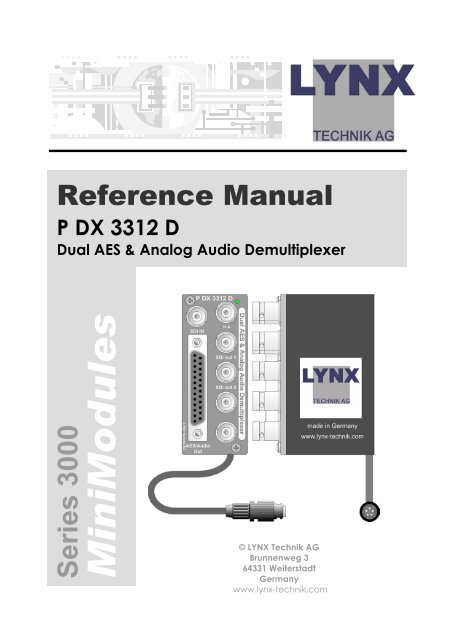
Product Description<br />
The P <strong>DX</strong> <strong>3312</strong> is a high quality AES and analog<br />
Audio de-multiplexer (Audio de-embedder)<br />
designed primarily for broadcast and professional<br />
applications.<br />
The Module accepts 1 SDI input signal with up to<br />
four audio groups embedded. One audio group<br />
can be selected and de-multiplexed and output as<br />
AES and analog Audio signals on a 110 Ohm<br />
SubD25 connection. Two reclocked outputs of the<br />
input signal are also provided to cascade several<br />
modules if required.<br />
The P <strong>DX</strong> <strong>3312</strong> has a variety of features, which<br />
include:<br />
• User selectable audio groups. (1 through 4)<br />
• Supports 525 / 625 line standards<br />
• Supports 4:3 / 16:9 aspect ratios<br />
• Supports 20 and 24 bit audio<br />
• Supports 8 and 10 bit video<br />
• Auto detect 270 / 360 Mbit operation<br />
• Local DIP-switches and LED's for control and<br />
status monitoring<br />
• All settings stored in non-volatile flash ram<br />
• Two reclocked outputs of input video<br />
Page 7
Reference Manual P <strong>DX</strong> <strong>3312</strong> D Version1.0<br />
Page 8<br />
The module has a built in micro-controller with local<br />
controls, status and alarm indicators and well as<br />
internal flash ram for storing setups. Any operational<br />
parameters configured and stored into the module<br />
are recalled when powered up.<br />
The P <strong>DX</strong> <strong>3312</strong> is part of the 3000 series of<br />
MiniModules, which offer high quality, modularity<br />
and flexibility in a very small form factor ideal for<br />
applications where space is at a premium.<br />
The modules can be used either stand alone using<br />
the optional power supply brick, or as part of a<br />
tightly integrated space saving system where up to<br />
10 MiniModules can be mounted utilizing the<br />
optional <strong>LYNX</strong> R FR 3005 / 3010 rack housing. This<br />
includes integrated power supply and optional<br />
redundant power supply.
Reference Manual P <strong>DX</strong> <strong>3312</strong> D Version1.0<br />
Functional Diagram<br />
Figure 1 below is the basic functional diagram for<br />
the P <strong>DX</strong> <strong>3312</strong> MiniModule.<br />
Figure 1- P <strong>DX</strong> <strong>3312</strong> Functional Diagram<br />
Module Layout<br />
Figure 2 shows the physical layout of the P <strong>DX</strong> <strong>3312</strong><br />
MiniModule. Video I/O is made through standard<br />
75 Ohm BNC video connections and Audio output<br />
through a 110 Ohm SubD25 connector. Module<br />
configuration is set via a small dip-switch located<br />
behind an access hole in the bottom of the<br />
module.<br />
If the module is being used in a stand alone<br />
application then the optional power supply (R PS<br />
3001 E, R PS 3001 U or R PS 3001-3) is required to<br />
power the module (not shown)<br />
Page 9
Reference Manual P <strong>DX</strong> <strong>3312</strong> D Version1.0<br />
Page 10<br />
Figure 2 – Module Layout
Reference Manual P <strong>DX</strong> <strong>3312</strong> D Version1.0<br />
Connections<br />
Audio / Video Connections<br />
The P <strong>DX</strong> <strong>3312</strong> MiniModule is configured with<br />
standard 75 Ohm BNC connectors for Video I/O.<br />
The Audio outputs are provided on a SubD25<br />
connector. Connection is self-explanatory for<br />
Video. Audio see below. We recommend the use<br />
of high quality video cable suitable for digital video<br />
connections to reduce the risk of interference or<br />
errors due to excessive cable attenuation.<br />
Note. Due to the compact design of the module it<br />
will be necessary to use a connection tool to<br />
secure the BNC video connectors to the module.<br />
Audio Output Connections (balanced)<br />
SubD 25 pin female connector.<br />
Pin<br />
Number<br />
Connection<br />
Pin<br />
Number<br />
Connection<br />
1 + Left 1 14 - Left 1<br />
2 GND Left 1 15 + Right 1<br />
3 - Right 1 16 GND Right 1<br />
4 + Left 2 17 - Left 2<br />
5 GND Left 2 18 + Right 2<br />
6 - Right 2 19 GND Right 2<br />
7 20<br />
8 21<br />
9 22<br />
10 + AES 2 23 - AES 2<br />
11 GND AES 2 24 + AES 1<br />
12<br />
13<br />
- AES 1 25 GND AES 1<br />
13 1<br />
25 14<br />
Page 11
Reference Manual P <strong>DX</strong> <strong>3312</strong> D Version1.0<br />
Page 12<br />
Power Connections<br />
If using the module in a stand-alone application<br />
use the separate R PS 3001 E (for Europe), R PS 3001<br />
U (USA) power brick option or the R PS 3001- desk<br />
power supply.<br />
DC Power Connector<br />
The MiniModule has a captive power lead fitted to<br />
the module, with a male 5 pin locking bayonet<br />
connector. This connection provides DC power<br />
and also data connectivity to the module.<br />
Connector wiring is shown below.<br />
Data Connection<br />
!<br />
i2C-SDA (data)<br />
i2C-SCL (clock)<br />
3<br />
4 2<br />
5 1<br />
Male Connector<br />
(view looking into connector from front)<br />
Power Connection<br />
GND<br />
+ 5V<br />
Caution<br />
Only use the optional <strong>LYNX</strong> R PS power<br />
modules. Ensure the 5-pin power<br />
connector is locked securely in place.
Installation<br />
Mechanical<br />
!<br />
Reference Manual P <strong>DX</strong> <strong>3312</strong> D Version1.0<br />
Stand Alone Operation<br />
The P <strong>DX</strong> <strong>3312</strong> MiniModule can be used in a stand<br />
alone application. There are two options for the use<br />
of the module in this way.<br />
a) Using the R FR 3005 Rack Frame 1 option. This<br />
allows up to any 10 of the MiniModules to be<br />
secured onto a rack frame assembly for 19 inch<br />
rack mounting. This keeps the modules secured,<br />
organized and out of the way. The R PS 3001<br />
power brick option or the R FR 3010 option is<br />
required to power each module. Please refer to<br />
the R FR 3005 Reference Manual supplied with<br />
this option for more details.<br />
b) Single Use. The MiniModule can be powered<br />
independently with the R PS 3001 option and<br />
used in any location where this functionality is<br />
required.<br />
Caution. Care needs to be taken<br />
when using the module in this way, as<br />
it is not physically secured. Keep the<br />
module away from the floor to avoid<br />
the risk of someone stepping or<br />
tripping on the unit, and locate the<br />
unit away from excessive sources of<br />
heat and any sources or moisture.<br />
If using more than one MiniModule in any<br />
installation, the R FR 3005/3010 Rack frame<br />
combination is highly recommended.<br />
Page 13
Reference Manual P <strong>DX</strong> <strong>3312</strong> D Version1.0<br />
Page 14<br />
Multiple Units<br />
Most applications will require more than one<br />
MiniModule, which can include any of the<br />
available Series 3000 MiniModule product range.<br />
There are two options for mounting multiple units.<br />
a) Using the R FR 3005 Rack Frame option. This<br />
allows up to any 10 of the MiniModules to be<br />
secured onto a rack frame assembly for 19 inch<br />
rack mounting. The R PS 3001 power brick<br />
option or the R FR 3010 option is required to<br />
power each module. Please refer to the R FR<br />
3005 Reference Manual for more details.<br />
b) Using the R FR 3010 Rack frame extension<br />
option. Can be combined with the R FR 3005<br />
Rack frame option. Each module plugs into a<br />
connection bus, which provides common<br />
power for all modules. (no R PS external power<br />
supplies are needed). Please refer to the<br />
respective reference manuals for these options<br />
for details of mechanical installation.<br />
The very small size and density of the MiniModules<br />
combined with the available rack frame options<br />
allows the addition of a complex and custom signal<br />
distribution system without taking any additional<br />
front rack space. The rack frames are designed for<br />
installation in the back of 19-inch racks where there<br />
is normally plenty of available space. Ideal for<br />
mobile truck installations and facility expansions<br />
where space is at a premium.
Reference Manual P <strong>DX</strong> <strong>3312</strong> D Version1.0<br />
Electrical Installation.<br />
Stand Alone Operation<br />
The MiniModule requires the R PS 3001 power brick<br />
option for stand-alone operation. Three versions are<br />
available R PS 3001 E for European markets, R PS<br />
3001 U for the US markets and the R PS 3001-3 desk<br />
power supply. Please ensure you have the correct<br />
power option for your region. The connection to<br />
the module is made with a small 5-pin connector,<br />
which has a twist bayonet securing system. Please<br />
make sure the connection is solid and locked in<br />
place. A strain relief is included within the module<br />
to prevent excessive strain on the connection.<br />
Signal connections should be made with care,<br />
please ensure connections are correct and<br />
compatible equipment is feeding / receiving the<br />
signals from the module or damage can result.<br />
!<br />
!<br />
Caution. Only use the optional <strong>LYNX</strong> R PS<br />
3001 power modules. Ensure the 5-pin<br />
power connector is locked securely in<br />
place.<br />
Caution. Care needs to be taken when<br />
using the module in this way, if it is not<br />
physically secured. Keep the module<br />
away from the floor to avoid the risk of<br />
someone stepping or tripping on the unit,<br />
and locate the unit away from excessive<br />
sources of heat and any sources or<br />
moisture.<br />
Page 15
Reference Manual P <strong>DX</strong> <strong>3312</strong> D Version1.0<br />
Settings and Control<br />
The P <strong>DX</strong> <strong>3312</strong> is configured via the integral 8position<br />
dip-switch (SW1), the 4-position dip-switch<br />
(SW2) and the two push buttons. This is located on<br />
the bottom of the module and can be accessed<br />
through the cutout provided (fig 2)<br />
Page 16<br />
Switch Settings<br />
Dip Switch 1 (SW1)<br />
Below the switch settings for the 8-position dipswitch<br />
are defined. Please see the section following<br />
the table for more detail on the switch function.<br />
Switch Setting Function SW 1<br />
1<br />
ON<br />
OFF<br />
Local adjustment enabled<br />
Local adjustment disabled<br />
2<br />
ON<br />
OFF<br />
Audio Group 1 Select<br />
3<br />
ON<br />
OFF<br />
Audio Group 2 Select<br />
4<br />
ON<br />
OFF<br />
Audio Group 3 Select<br />
5<br />
ON<br />
OFF<br />
Audio Group 4 Select<br />
6<br />
ON<br />
OFF<br />
Audio Mute ON<br />
Audio Mute OFF<br />
7<br />
ON<br />
OFF<br />
Not used<br />
8<br />
ON<br />
OFF<br />
Not used
Reference Manual P <strong>DX</strong> <strong>3312</strong> D Version1.0<br />
Switch Function Detail SW 1<br />
All settings are stored in Flash Ram inside the<br />
module (see Auto Store section in this manual).<br />
Settings will be recalled on power up.<br />
Dip Switch 1<br />
This switch enables local control using the dipswitches.<br />
ON enables local control and makes<br />
selections on the dipswitch active, and OFF<br />
disables local control (locking out any local<br />
changes)<br />
Note.<br />
There is a small LED next to dip switch position 1.This<br />
LED must be ON [green] before any local<br />
configuration changes to the dip switch will be<br />
recognized by the module. If Switch 1 is already set<br />
to ON [enable local adjustment] but the LED is OFF<br />
then toggle switch 1 ON-OFF-ON to enable local<br />
control.<br />
Dip Switch 2 through 5<br />
These switches are used to select the audio groups<br />
for de-embedding from the incoming SDI video<br />
stream. ON selects the Audio group, and OFF<br />
deselects.<br />
If no audio group is selected then no audio will be<br />
de-multiplexed.<br />
This module can only de-multiplex a single audio<br />
group. If more than one audio group is selected<br />
then by default group 1 will be de-multiplexed.<br />
Dip Switch 6<br />
This is used to select Audio mute ON / OFF.<br />
Selecting ON will mute any audio output from the<br />
module<br />
Dip Switch 7 and 8<br />
These switches are not used.<br />
Page 17
Reference Manual P <strong>DX</strong> <strong>3312</strong> D Version1.0<br />
Page 18<br />
Dip Switch 2 (SW2)<br />
Below the switch settings for the 4-position dipswitch<br />
are defined. Please refer to figure 2 for the<br />
location of the switch. Located either side of the<br />
switch are two push buttons [UP/DN] these are for<br />
gain adjustments.<br />
DIP Switch 2<br />
OFF<br />
ON<br />
123 4 DN UP<br />
Push Buttons<br />
Note. The module dip Switch is not a usual implicit<br />
selection switch used to define simple functionality.<br />
Setting the module is an interactive process, which<br />
involves setting the switch state to enable the<br />
setting or adjustment of a certain parameter, and<br />
then storing settings in flash memory. Switch<br />
function is shown in the table below, descriptions of<br />
the switch settings are provided in the next section.<br />
Switch 2 Setting Function<br />
1<br />
ON<br />
OFF<br />
High FS range (18dBu or 24dBu)*<br />
Low FS range (12dBu or 15dBu)*<br />
ON If Switch 1 = low range then FS = 15dBu<br />
2<br />
OFF<br />
If Switch 1 = high range then FS = 24dBu<br />
If Switch 1 = low range then FS = 12dBu<br />
If Switch 1 = high range then FS = 18dBu<br />
3<br />
ON<br />
OFF<br />
Adjust gain for AES channel 2<br />
Adjust gain for AES channel 1<br />
ON Set gain for selected channel on Switch 3<br />
4<br />
to unity (0dB)<br />
OFF Normal operation<br />
* Range depends on the setting of Switch 2
Reference Manual P <strong>DX</strong> <strong>3312</strong> D Version1.0<br />
Switch Function Detail SW2<br />
Switch 1 – This switch is used to select either high or<br />
low full scale (FS) gain range for the module.<br />
Selecting ON will set the high FS range which can<br />
be either 18 or 24 dBu (depending on the setting of<br />
Switch 2) Selecting OFF will set low FS range which<br />
can be either 12 or 15 dBu (depending on the<br />
setting of Switch 2)<br />
Switch 2 – This is used in conjunction with Switch 1<br />
and will select one of the two possible values<br />
determined by the setting of Switch 1. (Refer to<br />
table on previous page)<br />
Switch 3 – This switch is used to select the AES<br />
channel for gain adjustment. ON selects channel 2<br />
OFF selects channel 1. Gain is adjusted using the<br />
[UP/DN] push buttons *<br />
Switch 4 – This switch is used to set unity gain on the<br />
channel selected using switch 3. ON will set unity<br />
gain* OFF will provide for adjustment of gain.<br />
* When the settings have been made wait 10<br />
seconds for the new value to be stored into flash<br />
ram, seen by the alarm LED flashing yellow four<br />
times.<br />
Page 19
Reference Manual P <strong>DX</strong> <strong>3312</strong> D Version1.0<br />
Page 20<br />
Factory Preset Condition<br />
The P <strong>DX</strong> <strong>3312</strong> is delivered preset for the following<br />
mode of operation:<br />
• Audio Group 1 selected<br />
• Audio Mute OFF<br />
• Full Scale (FS) Range LOW<br />
• Full Scale = 15dBu<br />
• Normal operation<br />
If this is the mode of operation required, then no<br />
adjustments are necessary.
Reference Manual P <strong>DX</strong> <strong>3312</strong> D Version1.0<br />
Alarm/LED Status Indicators<br />
The P MX <strong>3312</strong> module has built in LED indicators,<br />
which serve as alarm and status indication for the<br />
module. Function is described below. The Indicators<br />
are found on the bottom of the module and can<br />
be seen through the access holes provided. (Figure<br />
2)<br />
Module Edge Status LEDs<br />
4 Status LEDs are provided on the module edge<br />
LED 1 = AES Channel 1<br />
LED 2 = AES Channel 2<br />
LED Color Indication<br />
Green AES signal present, no errors<br />
Yellow AES signal present, muted<br />
Red AES signal not present<br />
Channel Condition Indicators<br />
One LED is provided for each channel LED 3 =<br />
Channel 1 and LED 4 = Channel 2<br />
LED Color Indication<br />
Green Digital Audio OK<br />
Yellow Digital Audio parity error<br />
Red Digital Audio input missing<br />
Front Panel Alarm Indicator<br />
There is also a single alarm LED on the front side of<br />
the module, which is designed for quick and easy<br />
indication of a problem condition in installations<br />
where visible access to the bottom of the module is<br />
not convenient.<br />
LED Color Indication<br />
Green SDI with two AES signals in selected group<br />
present<br />
Yellow SDI present, but only one AES in selected<br />
group<br />
Red No SDI signal or no Audio present<br />
LED OFF indicates power is lost, or there is a power<br />
supply fault.<br />
Page 21
Reference Manual P <strong>DX</strong> <strong>3312</strong> D Version1.0<br />
Specifications (P <strong>DX</strong> <strong>3312</strong> D)<br />
Inputs<br />
SDI Video 1 x Serial Digital Video. SMPTE 259M-C<br />
Input impedance 75 Ohm (BNC connectors)<br />
Outputs Video<br />
Signal (Video) 2 reclocked Serial Digital Video. SMPTE 259M-C<br />
Output impedance 75 Ohm (BNC connectors)<br />
Output level 0.8V p-p<br />
Cable Equalization > 250m (Belden 8281 / 270Mbit/s)<br />
Jitter < 0.2 UI<br />
Return loss > 15dB (270 MHz)<br />
Outputs Digital Audio<br />
Signal (DigitalAudio) 2 x AES3, 24 Bit<br />
Output impedance 110 Ohm (balanced) (SubD25 female connector)<br />
Output level 4V p-p nominal.<br />
Outputs Analog Audio<br />
Signal 2 x balanced stereo outputs (one stereo output per<br />
channel)<br />
Impedance 50 Ohm (SubD25 female connector)<br />
Max Level 24 dBu into 10K Ohms<br />
0dB FS level Selectable ( 12dBu, 15dBu, 18dBu or 24dBu)<br />
Gain Adjustable between -90dB to 6dB (in 0.5dB incr.)<br />
Quantisation 24 bits<br />
Noise Floor < -90 dBu (A-weighted)<br />
Distortion < 0.002% (20 Hz to 20 KHz)<br />
Frequency Response +\- 0.2dB (20 Hz to 20 KHz)<br />
Crosstalk < -90dB (20 Hz to 20 KHz)<br />
Added jitter < 2ns<br />
Electrical Specifications<br />
Operating Voltage + 5V DC<br />
Power Consumption 6 W<br />
Connection DC input via 5 pin locking bayonet connector<br />
Safety IEC 950/ EN 60950/VDE 0805<br />
Mechanical<br />
Size 85.5mm x 35.3mm x 58mm + connectors<br />
Weight 350g<br />
Ambient<br />
Temperature 5°C to 35°C Maintaining specifications<br />
-20°C to +70°C Storage<br />
Humidity Max. 80% non condensing<br />
Supplied Accessories<br />
Documentation P <strong>DX</strong> <strong>3312</strong> D Reference Manual and Quick<br />
Reference Guide<br />
Page 22
Reference Manual P <strong>DX</strong> <strong>3312</strong> D Version1.0<br />
Available Options<br />
Below is a list of available options for the P <strong>DX</strong> <strong>3312</strong><br />
MiniModule. Please refer to product brochures or<br />
our web site for more detailed information.<br />
Model Description<br />
R PS 3001 E<br />
R PS 3001 U<br />
R PS 3001-3<br />
R FR 3004<br />
R FR 3005<br />
R FR 3010<br />
R PS C15<br />
R PS C25<br />
R PS 5010<br />
External brick power supply module for<br />
Series 3000 MiniModules. European market<br />
version. 100-240 VAC input, +5V DC output.<br />
External brick power supply module for<br />
Series 3000 MiniModules. USA market<br />
version. 110-240 VAC input, +5V DC output.<br />
External desk power supply module for<br />
Series 3000 MiniModules. 110-240 VAC<br />
input, +5V DC output.<br />
Mounting Support for 4 MiniModules<br />
Rack Frame 1. This is a basic 19 inch rack<br />
mountable frame which can accommodate<br />
10 MiniModules with power bricks R PS 1 or<br />
can be extended with the R FR 3010.<br />
Rack Frame 2. This is a card cage with<br />
integrated central power supply and<br />
optional redundant power supply, which<br />
can accommodate 10 MiniModules. Can be<br />
combined with R FR 3005<br />
1.5m cable extension to connect one<br />
MiniModule to R FR 3010<br />
2.5m cable extension to connect one<br />
MiniModule to R FR 3010<br />
Redundant power supply for the R FR 3010<br />
card cage<br />
Page 23
Reference Manual P <strong>DX</strong> <strong>3312</strong> D Version1.0<br />
Parts List<br />
Page 24<br />
Due to the very dense design and high level of<br />
integration there are no user serviceable electronic<br />
assemblies within the P <strong>DX</strong> 2312 module.<br />
P <strong>DX</strong> <strong>3312</strong> D Mini Module (complete)<br />
Description Dual Analog Audio<br />
Demultiplexer<br />
Model Number P <strong>DX</strong> <strong>3312</strong> D<br />
Part Number 6.155.002.255<br />
Service<br />
If you are experiencing problems, or have questions<br />
concerning your P <strong>DX</strong> <strong>3312</strong> MiniModule please<br />
contact your local distributor for assistance.<br />
We offer a fixed cost service exchange program for<br />
defective Series 3000 MiniModules out of Warranty.<br />
Please contact your distributor or check our web<br />
site for details on this program.<br />
More detailed information and product updates<br />
may be available on our web site:<br />
www.lynx-technik.com<br />
You will also find links to contact us directly for<br />
assistance.
Contact Information<br />
Reference Manual P <strong>DX</strong> <strong>3312</strong> D Version1.0<br />
Please contact your local distributor; this is your<br />
local and fastest method for obtaining support and<br />
sales information.<br />
<strong>LYNX</strong> <strong>Technik</strong> can be contacted directly using the<br />
information below.<br />
Address <strong>LYNX</strong> <strong>Technik</strong> <strong>AG</strong><br />
Brunnenweg 3<br />
64331 Weiterstadt<br />
Germany.<br />
Phone + 49 (0) 6150 1817 0<br />
Fax + 49 (0) 6150 1817 10<br />
Website www.lynx-technik.com<br />
E-Mail info@lynx-technik.com<br />
<strong>LYNX</strong> <strong>Technik</strong> manufactures a complete range of<br />
high quality modular products for broadcast and<br />
Professional markets, please contact your local<br />
representative or visit our web site for more product<br />
information.<br />
Page 25
Reference Manual P <strong>DX</strong> <strong>3312</strong> D Version1.0<br />
Page 26<br />
This Page is intentionally left blank
Reference Manual P <strong>DX</strong> <strong>3312</strong> D Version1.0<br />
Notes<br />
Page 27