
You also want an ePaper? Increase the reach of your titles
YUMPU automatically turns print PDFs into web optimized ePapers that Google loves.
IntraMax Boring System<br />
Setup Instructions<br />
1.9-14” Boring (48.3-355.8)<br />
.35-9.8” OD Turning (9-248.9)<br />
<br />
1. After assembling the insert holders to the diameter extender, you are ready to preset the head to the desired bore<br />
size. Leaving a slight amount of pressure on the two cap screws, use the adjustment set screw to line up the “tick<br />
marks” on either side of the diameter extender. The insert holders adjust independently. So after adjusting each<br />
side, use a vernier caliper to determine diameter size. Remember, if the insert holders are not equal distance from<br />
the center of rotation, the bore produced will be oversized.<br />
2. To verify that the insert holders are equal distance from center, the easiest method (other than using a presetter)<br />
is to place the tool into the machine spindle. Then, using a magnetic base indicator, spin the tool to verify that the<br />
reading is equal.<br />
3. Once the diameter is set, tighten the cap screws on each side of the boring head.<br />
<br />
1. After installing the insert cartridge onto the finish boring head, install the finishing head onto the diameter<br />
extender. Before tightening the cap screws, use the rough adjustment screw to position the boring head close to<br />
the final bore size.<br />
2. Before turning the adjustment dial, be sure to loosen side locking set screw. Do not leave any pressure on the<br />
locking mechanism when adjusting for size. This will decrease the life and accuracy of the adjustment mechanism.<br />
3. After loosening the side lock set screw, turn the dial to achieve the desired diameter. The dial is in increments of<br />
.0002” on diameter. Once you have obtained the target diameter, tighten the locking set screw before using. There<br />
is no need to “overtighten” this set screw.<br />
4. Now you are ready to bore a test bore. Typically, there is a need for further adjustment after the test cut due to<br />
deflection caused by cutting pressures. If this is the case, repeat the above procedure.<br />
<br />
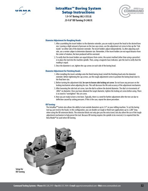
The IntraMax System also allows the ability to turn outside diameters up to 3.9” on your milling machine. To set the boring<br />
tool up, just reverse the heads. In this configuration, you can double cut rough or finish turn applications up to 2.280” long<br />
when using the OD extension blocks. The extension blocks not only give you the extra travel, but also allow the use of the rough<br />
adjustment mechanism to help preset the tool. Because OD turning requires the spindle to be reversed, it is required that the<br />
Beta Modul® be used when OD turning.<br />
Setup for<br />
OD Turning<br />
800.328.2197800.555.7694support@commandtool.comwww.commandtool.com<br />
32