
Create successful ePaper yourself
Turn your PDF publications into a flip-book with our unique Google optimized e-Paper software.
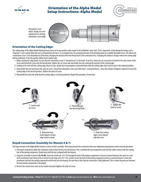
Orientation of the Alpha Modul<br />
Setup Instructions: Alpha Modul<br />
Orientation screw<br />
detail. Simple set screw<br />
adjustment for altering<br />
orientation screw depth<br />
Orientation of the Cutting Edge:<br />
The cutting edge of the Alpha Modul finishing head can be set to any position with regard to the toolholder’s drive slots. This is important so that during the boring cycle a<br />
“drag line” is not created when the tool is removed from the bore. To accomplish this, the mounting threads of the finishing head are a double-threaded screw. This allows the<br />
“orientation screw” to be threaded out of the head, changing the distance from the thread lead to the connection face. Changing this distance changes where the cutting edge<br />
will be positioned. To do this quickly, follow these simple steps:<br />
1. Before starting the adjustment, be sure that the orientation screw is “bottomed out” in the head. To do this, loosen the set screw that is located in the axial center of the<br />
screw and thread the screw into the boring head. Tighten the set screw and reassemble the tool, noticing the position of the cutting edge.<br />
2. Looking at the tool with the cutting edge closest to you, decide how many degrees counterclockwise that the cutting edge must travel to get to the required position.<br />
3. Disassemble the tool and loosen the axial set screw. Thread the orientation screw out of the head - counterclockwise - twice the number of degrees required to locate the<br />
cutting edge at the desired position. Tighten the axial set screw.<br />
4. Reassemble the tool and verify that the cutting edge is correctly positioned. Repeat the procedure, if necessary.<br />
1. Loosen axial<br />
set screw<br />
2. Thread the stud<br />
into the boring head<br />
3. Tighten the<br />
axial set screw<br />
4. Determine how<br />
many degrees cutting<br />
edge needs to rotate<br />
5. Verify that cutting<br />
edge is now aligned<br />
with drive slot<br />
Keyed Connection Assembly for Mounts 6 & 7:<br />
The larger mounts in the Alpha Modul System use keys in their assembly. These keys prevent the connection from over-tightening during heavy metal removal operations.<br />
1. The keyed components utilize the orientation stud to draw the key into the keyway. First, assemble the two components until the key makes contact with the mating<br />
face of the joining component. Rotate back until the key is aligned with the keyway.<br />
2. Using the assembly X-wrench (), insert the small end .314” (8) through the back of the joining component to loosen (counterclockwise) the axial set screw<br />
of the orientation stud. Reverse the X-wrench to the large end .472” (12), reinsert it into the back of the joining component and turn counterclockwise to draw the<br />
orientation stud into the joining component and the key into the keyway. Be sure that at this step the connection is fully tightened. This is where the pressure between<br />
the two joining components is developed.<br />
3. Reverse the wrench once more to the smaller end and retighten the axial set screw.<br />
800.328.2197800.555.7694support@commandtool.comwww.commandtool.com