Quick Shifter - MPS Racing
Quick Shifter - MPS Racing
Quick Shifter - MPS Racing

Create successful ePaper yourself
Turn your PDF publications into a flip-book with our unique Google optimized e-Paper software.
Innovative <strong>Racing</strong> Electronics<br />
<strong>MPS</strong> <strong>Quick</strong> <strong>Shifter</strong> Installation Instructions<br />
The first thing to do is remove the seat, fuel<br />
tank, and possibly the front fairing if<br />
equipped. You will need plenty of room to<br />
work.<br />
<strong>Shifter</strong> Switch Mounting – You will need to<br />
fabricate your own bracket for the switch.<br />
There are a lot of ways to mount the switch.<br />
Basically, the better the mounting the better<br />
the unit will operate. Switch adjustment is<br />
critical to proper operation. Mount the<br />
switch so the spring is pulling the pin out of<br />
the switch when the shifter is up shifted.<br />
Electrical Connections – You will need to<br />
locate and test a few things on your bike<br />
before you start wiring. A good ground, a<br />
ignition switched 12 volt power source, and<br />
the ignition coils.<br />
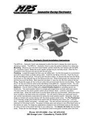
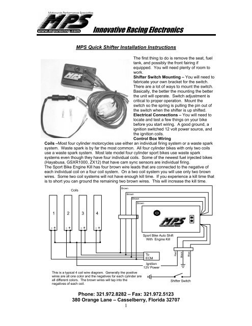
Control Box Wiring<br />
Coils –Most four cylinder motorcycles use either an individual firing system or a waste spark<br />
system. Waste spark is by far the most common. All four cylinder bikes with only two coils<br />
use a waste spark system. Most late model four cylinder sport bikes use waste spark<br />
systems even though they have four individual coils. Some of the newest fuel injected bikes<br />
(Hayabusa, GSXR1000, ZX12) that have cam sync sensors are individual firing.<br />
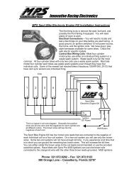
The Sport Bike Engine Kill has four brown wire leads that are connected to the negative of<br />
each individual coil on a four coil system. On a two coil system you will use only two brown<br />
wires. Some two coil systems will not have enough kill time. If you experience a kill time that<br />
is to short you can ground the remaining two brown wires. This will increase the kill time.<br />
Coils<br />
Brown<br />
Brown<br />
Brown<br />
Brown<br />
1 2 3 4<br />
- + - + - + - +<br />
Sport Bike Auto Shift<br />
With Engine Kill<br />
To<br />
ECM<br />
Ignition<br />
12V Power<br />
This is a typical 4 coil wire diagram. Generally the positive<br />
wires are all one color and the negatives for each cylinder are<br />
all different colors. The brown wires will tap into the<br />
negatives of each coil.<br />
Red<br />
Black<br />
Blue<br />
<strong>Shifter</strong> Switch<br />
Phone: 321.972.8282 – Fax: 321.972.5123<br />
380 Orange Lane – Casselberry, Florida 32707<br />
1
Innovative <strong>Racing</strong> Electronics<br />
You can either solder the brown wires to the coil leads (recommended) or use the provided<br />
scotchlok splices<br />
Power, Ground, and Activation Lead – The red wire is connected to a ignition switched 12<br />
volt power source. Do not attach direct to battery! The black wire is connected to a good<br />
ground, preferably the battery negative post. The blue wire is the activation lead. When a<br />
ground is applied to this wire the unit kills the motor for the specified time period. The blue<br />
activation lead is connected to the green/yellow lead on the shifter switch.<br />
<strong>Shifter</strong> Switch – The shift switch has two wires. The black wire is connected to a good<br />
ground and the green/yellow wire is connected to the blue activation lead on the kill box.<br />
<strong>Shifter</strong> Switch Adjustment – To adjust the shifter switch, unplug the shifter switch<br />
green/yellow wire from the kill box. Using a test light, clip the test light to the positive side of<br />
the battery. Test the light by probing a known good ground. The light should light up. Put<br />
the probe in the green/yellow wire lead from the shifter switch. Move the shifter with your<br />
hand. Just as you start to feel pressure on the shifter or slightly later is when the switch<br />
should operate. The test light will light when the switch is operated. You can fine-tune this<br />
adjustment later, after you have ridden the bike.<br />
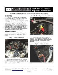
Setting Kill Time – Kill time is the amount of time the engine stays dead between gears<br />
during a shift. Generally the shorter the kill time the quicker the shift. The proper kill time will<br />
Kill Time<br />
Adjustment<br />
Potentiometer<br />
vary from bike to bike. It’s generally better to<br />
start with too much kill time and work your<br />
way quicker. We generally start at around 75<br />
ms. of kill time. The Kill Time is adjusted via<br />
a small potentiometer accessed through the<br />
grommet on the front of the unit. Using a<br />
small screwdriver Carefully turn the pot<br />
clockwise to the end of its travel. This is 100 ms of kill time. Now, carefully turn the pot<br />
screw counterclockwise to the end of its travel. This is 50 ms of kill time. Halfway in between<br />
is 75 ms. The pot only goes from 7 o’clock to 5 o’clock so don’t force it, they break easily!<br />
Testing The System – With the bike in neutral, bring the rpm up to around 3000 rpm and pull<br />
out the spring to operate the swifter switch. You should hear a slight hesitation in the engine<br />
each time you pull out the spring. If you don’t hear a hesitation the brown wires are probably<br />
not hooked up correctly or the shift switch black wire isn’t grounded properly. With these<br />
preliminary tests done you can put the bike back together and go for a ride! Shift it at lower<br />
rpms first to make sure it is in fact operating properly. If you have any more questions we<br />
have a Frequently Asked Questions page at our web site as well as the telephone tech<br />
support. Thank you for your purchase of this <strong>MPS</strong> product. All products sold by <strong>MPS</strong> are for<br />
use at closed course competition events and not for use on public streets or highways.<br />
Phone: 321.972.8282 – Fax: 321.972.5123<br />
380 Orange Lane – Casselberry, Florida 32707<br />
2