Installation / Service Manual - FREE SHIPPING - Heating and Air ...
Installation / Service Manual - FREE SHIPPING - Heating and Air ...
Installation / Service Manual - FREE SHIPPING - Heating and Air ...

You also want an ePaper? Increase the reach of your titles
YUMPU automatically turns print PDFs into web optimized ePapers that Google loves.
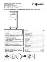
<strong>Installation</strong> / <strong>Service</strong> <strong>Manual</strong><br />
for Vitogas 050, RS Series<br />
Gas-fired, atmospheric cast iron boiler<br />
550 to 1050 MBH / 161 to 308 kW<br />
IMPORTANT: READ AND SAVE THESE INSTRUCTIONS FOR FUTURE REFERENCE<br />
These instructions cover the installation, operation <strong>and</strong><br />
servicing of the Viessmann Vitogas 50, RS series of cast-iron<br />
sectional atmospheric gas-fired hot water boilers. These<br />
instructions must be read thoroughly prior to installation.<br />
These instructions must be saved <strong>and</strong> made available to<br />
service technicians when required. Install boiler according to<br />
these instructions.<br />
The installation of this unit shall be in accordance with local<br />
codes or, in the absence of local codes, use CSA-B149.1 or .2<br />
<strong>Installation</strong> Codes for Gas Burning Appliances for Canada. For<br />
U.S. installations use ANSI Z223.1. Always use latest editions<br />
of codes.<br />
Where required by the authority having jurisdiction, the<br />
installation must conform to the St<strong>and</strong>ard for Controls <strong>and</strong><br />
Safety Devices for Automatically Fired Boilers, ANSI/ASME<br />
CSD-1.<br />
These instructions must be placed in an envelope <strong>and</strong> affixed<br />
to the boiler.<br />
Contents:<br />
Page:<br />
Technical Data..........................................................................3<br />
Boiler Features .........................................................................4<br />
<strong>Installation</strong>.................................................................................4<br />
Gas Connections ......................................................................7<br />
Water Connections ...................................................................8<br />
Vent Connections ...................................................................10<br />
Accessories ............................................................................10<br />
Start-up <strong>and</strong> Operating Instructions........................................11<br />
Maintenance ...........................................................................13<br />
Troubleshooting ......................................................................17<br />
Piping Layouts ........................................................................18<br />
Wiring Diagrams .....................................................................22<br />
<strong>Installation</strong> Checklist ...............................................................24<br />
Replacement Parts List...........................................................25<br />
Assembly of cast-iron block using draw tool...........................30<br />
Viessmann Manufacturing Company Inc.<br />
750 McMurray Road<br />
Waterloo, Ontario • N2V 2G5 • Canada<br />
Tel. (519) 885-6300 • Fax (519) 885-0887<br />
www.viessmann.ca • mail@viessmann.ca<br />
5167 456 v1.2 03/2007<br />
®<br />
Viessmann Manufacturing Company (U.S.) Inc.<br />
45 Access Road<br />
Warwick, RI • 02886 • U.S.A.<br />
Tel.: (401) 732-0667 Fax: (401) 732-0590<br />
www.viessmann-us.com • mail@viessmann-us.com
This “Attention” symbol is located beside all<br />
important safety recommendations. Please follow<br />
the instructions in detail to avoid property damage,<br />
severe personal injury, or loss of life.<br />
Warning: If the information in this manual is not<br />
followed exactly, a fire or explosion may result<br />
causing property damage, personal injury, or<br />
loss of life.<br />
Do not store or use gasoline or other flammable liquids<br />
in the vicinity of this or any other appliance.<br />
WHAT TO DO IF YOU SMELL GAS<br />
• Do not try to light any appliances.<br />
• Do not touch any electrical switches, do not use any<br />
phone in your building.<br />
• Immediately call your gas supplier from a neighbor’s<br />
phone. Follow the gas supplier’s instructions.<br />
• If you cannot reach your gas supplier, call the fire<br />
department.<br />
<strong>Installation</strong> <strong>and</strong> service must be performed by a qualified<br />
installer, service agency or the gas supplier.<br />
Warning:<br />
The installation, adjustment, service, <strong>and</strong> maintenance<br />
of this boiler must be done by a licensed professional<br />
service technician who is qualified <strong>and</strong> experienced in<br />
the installation, service, <strong>and</strong> maintenance of commercial<br />
gas-fired hot water boilers. There are no user<br />
serviceable parts on the boiler, burner, or control.<br />
Failure to heed this warning can cause property damage,<br />
severe personal injury, or loss of life.<br />
Warning:<br />
Improper installation, adjustment, service, or<br />
maintenance can cause flue products to flow into living<br />
space. Flue products contain poisonous carbon<br />
monoxide gas which can cause nausea or asphyxiation<br />
resulting in severe personal injury or loss of life.<br />
Warning:<br />
Before each heating season begins, have the following<br />
service <strong>and</strong> maintenance done by a professional service<br />
technician:<br />
1) Boiler heat exchanger inspected <strong>and</strong> cleaned.<br />
2) Vent system inspected for deterioration, leaks,<br />
corrosion, proper draft, <strong>and</strong> proper operation. Check<br />
vent system for compliance with local <strong>and</strong> national<br />
code requirements. Repair or replace as required.<br />
3) Burner checked <strong>and</strong> if necessary adjusted for<br />
proper combustion <strong>and</strong> operation. Check for<br />
adequate supply of fresh outside combustion <strong>and</strong><br />
ventilation air.<br />
Neglecting to perform necessary maintenance can cause<br />
unsafe operation.<br />
Warning:<br />
Never operate the boiler without an installed venting<br />
system which safely vents all products of combustion to<br />
the outdoors. The vent system must comply with all<br />
applicable local <strong>and</strong>/or national codes.<br />
Improper, incomplete, obstructed, or deteriorated vent<br />
systems can present a serious risk of flue gases leaking<br />
into living space which could cause carbon monoxide<br />
poisoning.<br />
Warning:<br />
Never operate the boiler without an adequate supply of<br />
fresh combustion air. This boiler needs fresh air for safe<br />
operation <strong>and</strong> must be installed so there are provisions<br />
for adequate combustion <strong>and</strong> ventilation air. All<br />
combustion <strong>and</strong> ventilation air must be supplied from<br />
the outside. Failure to heed this warning can cause<br />
severe personal injury or loss of life.<br />
Warning:<br />
Should overheating occur or the gas supply fail to shut<br />
off, do not disconnect the electrical supply to the pump.<br />
Instead, shut off the gas supply at a location external to<br />
the appliance.<br />
Warning:<br />
Shut off all electrical power <strong>and</strong> turn off gas or oil supply<br />
to boiler before performing any service or maintenance<br />
on the boiler, burner, or control. Failure to follow this<br />
warning could result in electrical shock, serious<br />
personal injury or loss of life.<br />
Do not use this boiler if any part has been under water.<br />
Immediately call a qualified service technician to inspect<br />
the boiler <strong>and</strong> to replace any part of the control system<br />
<strong>and</strong> any gas control which has been under water.<br />
2<br />
Do not store chemicals containing chlorine or other<br />
corrosive materials near the boiler, such as bleach,<br />
cleaning solvents, detergents, acids, hair spray, spray<br />
cans, paint thinners, paint, water softener salt,<br />
refrigerants.
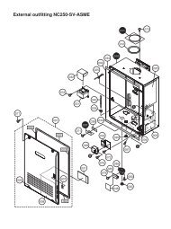
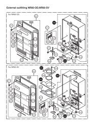
FGC<br />
Height 2<br />
Height 1<br />
Height<br />
PRV<br />
PC<br />
BD<br />
Total width<br />
BWS<br />
GC2<br />
GC1<br />
BWR<br />
15 3 ⁄4"/400mm<br />
Depth<br />
Total depth<br />
4 1 ⁄2"/<br />
110mm 19"/481 mm<br />
32 1 ⁄2"/830mm<br />
50 1 ⁄2"/1284mm<br />
52 1 ⁄2"/1335mm<br />
Legend<br />
BD Boiler Drain<br />
BWR Boiler Water Return<br />
BWS Boiler Water Supply<br />
FGC Flue Gas Collar<br />
GC1<br />
GC2<br />
Main Gas Connection<br />
Pilot Gas Connection<br />
PC<br />
PRV<br />
Pilot Cover Plate<br />
Pressure Relief Valve Connection<br />
Technical Data<br />
Boiler Model Model No. RS-8 RS-11 RS-14<br />
CSA input full load *1 MBH 550 800 1050<br />
kW 161 234 308<br />
partial load *2 MBH 372 541 710<br />
kW 109 158 208<br />
CSA output full load *1 MBH 468 680 893<br />
kW 137 199 261<br />
partial load *2 MBH 316 460 604<br />
kW 93 135 177<br />
Combustion efficiency % 85.0 85.0 85.0<br />
Heat exchanger ft 2 99.47 140.63 181.79<br />
surface area m 2 9.2 13.1 16.9<br />
Cast-iron sections 8 11 14<br />
Burners 7 10 13<br />
Manifold pressure<br />
Natural gas full load "w.c. 3.5 3.5 3.5<br />
partial load *3 "w.c. 1.3 1.3 1.3<br />
Propane gas full load "w.c. 10 10 10<br />
partial load *3 "w.c.<br />
Man. gas supply pressure *4 "w.c. 14 14 14<br />
Dimensions<br />
Depth inches 34 3 ⁄4 34 3 ⁄4 34 3 ⁄4<br />
mm 883 883 883<br />
Width inches 36 1 ⁄4 49 1 ⁄2 69 1 ⁄4<br />
mm 921 1255 1582<br />
Height inches 53 3 ⁄4 53 3 ⁄4 53 3 ⁄4<br />
mm 1366 1366 1366<br />
Boiler Model Model No. RS-8 RS-11 RS-14<br />
Overall dimensions<br />
Total depth inches 47 47 47<br />
mm 1195 1195 1195<br />
Total width inches 36 1 ⁄4 49 1 ⁄2 62 1 ⁄4<br />
mm 921 1255 1582<br />
Total height<br />
Height 1 (control unit in inches 60 1 ⁄4 60 1 ⁄4 60 1 ⁄4<br />
position for operation) mm 1531 1531 1531<br />
Height 2 (control unit in inches 73 1 ⁄2 73 1 ⁄2 73 1 ⁄2<br />
position for servicing) mm 1867 1867 1867<br />
Weight, boiler with insulation, lbs 1280 1709 2138<br />
burners <strong>and</strong> packaging kg 582 777 972<br />
Boiler water content USG 20 28 35<br />
ltr 77 106 134<br />
Max. operating pressure psig 60 60 60<br />
kPa 414 414 414<br />
Boiler connections<br />
Boiler supply <strong>and</strong> return Ø" 2 2 2<br />
(male thread)<br />
Boiler drain Ø" 3 ⁄4<br />
3 ⁄4<br />
3 ⁄4<br />
Gas supply connection Ø 1 1 1 ⁄4 1 1 ⁄4<br />
(male thread)<br />
Vent pipe collar inches 10 12 14<br />
250 300 350<br />
*1 Combustion results are based on a heating system supply temperature of 167 o F / 75 o C, return 140 o F / 60 o C<br />
*2 For two-stage boilers only<br />
*3 Parial load manifold pressure is factory preset. Any attempt to readjust in the field will render boiler warranty null <strong>and</strong> void.<br />
*4 If the gas supply pressure is higher than the maximum permissible value, a separate field supplied gas regulator must be<br />
installed upstream of the boiler gas train.<br />
For for information regarding other Viessmann System Technology componentry, please reference documentation of the<br />
respective product.<br />
3
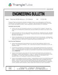
1.0 Shipping of boiler<br />
The boiler is shipped in two pieces. An assembled castiron<br />
heat exchanger is shipped on a wooden pallet. The<br />
second piece is a crate containing the jacket, draft<br />
hood, gas train, <strong>and</strong> manifold. Boiler requires final field<br />
assembly.<br />
Cast iron<br />
heat exchanger<br />
The boiler comes with water connections on the right<br />
h<strong>and</strong> side in the st<strong>and</strong>ard configuration. If required, the<br />
connections can be made on the left side by reversing<br />
the gas inlet pipe <strong>and</strong> reversing the flange connections<br />
for the water connections. See section 2.2 <strong>and</strong> piping<br />
layouts Figs. 11, 23, 24 <strong>and</strong> 25.<br />
Max. boiler operating pressure 60 psi (414 kPa).<br />
Max. boiler temperature 248°F (120°C).<br />
Any damages caused by operation in excess of the<br />
above mentioned temperatures <strong>and</strong> pressure are not<br />
the responsibility of Viessmann Manufacturing<br />
Company Inc.<br />
List of parts shipped<br />
Rear<br />
23 1 ⁄ 2˝<br />
(600mm)<br />
Fig. 1<br />
Assembled cast-iron heat exchanger<br />
Front<br />
Wooden pallet<br />
For a complete list of parts refer to Replacement Parts<br />
List on page 25.<br />
2.0 <strong>Installation</strong><br />
Important:<br />
Note that the sheet metal enclosure is designed in such<br />
a way that the enclosure can be installed after all water<br />
piping, pipe insulation, draft hood <strong>and</strong> venting has been<br />
completed. Install sheet metal enclosure last to<br />
minimize the chance of damage to the enclosure. Final<br />
gas piping is done after installing sheet metal enclosure.<br />
RS-8<br />
RS-11<br />
RS-14<br />
56 1 ⁄ 2˝<br />
56 1 ⁄ 2˝<br />
66 1 ⁄ 2˝<br />
Crate is 42˝ deep for all sizes<br />
Fig. 2<br />
Crate containing draft hood <strong>and</strong> jacket<br />
25˝<br />
Before boiler is connected to a piping/heating system<br />
which has been in service (boiler is a replacement<br />
boiler), piping system should be flushed thoroughly with<br />
water in order to remove sludge, rust, debris, or other<br />
contaminants, especially in large piping systems such<br />
as old gravity systems. Failure to remove contaminants<br />
can lead to boiler failure.<br />
Note: The RS boiler is for use in closed loop hot water<br />
forced circulation systems only. Do not use in<br />
steam applications.<br />
2.1 <strong>Installation</strong> of supply <strong>and</strong> return flanges<br />
Both pieces (Fig. 1 <strong>and</strong> Fig. 2) will fit through a st<strong>and</strong>ard<br />
32˝ doorway. Casting may be ordered split in two or<br />
more sections to facilitate h<strong>and</strong>ling. Refer to separate<br />
heat exchanger assembly instructions.<br />
Assembly of split cast-iron heat exchanger requires the<br />
use of a Viessmann draw tool, which must be specified<br />
at time of ordering. See page 30 for use of draw tool.<br />
1.1 Boiler features<br />
4<br />
The Vitogas 50, RS boiler series includes the following<br />
features <strong>and</strong> st<strong>and</strong>ard equipment:<br />
– Cast-Iron sections of wet base design, fully<br />
assembled<br />
– Boiler ID coding card<br />
– Intermittent pilot ignition system<br />
– Stainless steel burner tubes<br />
– Horizontal to vertical draft diverter<br />
– Accessory pack including 50 psi pressure relief valve,<br />
air vent <strong>and</strong> pressure gauge<br />
Prior to placing the boiler in its installed position, ensure<br />
that the supply <strong>and</strong> return flanges are on the correct side<br />
of the boiler. The st<strong>and</strong>ard configuration has the supply,<br />
return connections on the right side. To reverse the<br />
water connections see section 2.2. Also see Fig. 23 on<br />
page 18.<br />
2.2 <strong>Installation</strong> with piping on left side<br />
To install boiler with water piping on the left side instead<br />
of the right, the following must be done:<br />
a) Remove the supply flange <strong>and</strong> gasket, <strong>and</strong> the<br />
opposite flange threaded 1˝ NPT (i.e. pressure<br />
relief valve fitting).<br />
b) Remove the return flange, gasket, 60mm studs,<br />
<strong>and</strong> the opposite flange threaded 3 ⁄ 4˝ NPT (i.e. drain<br />
cock fitting). NOTE that the return flange is fitted<br />
with a water distribution tube. Holes are drilled to<br />
distribute water vertically into the casting <strong>and</strong><br />
horizontally into the wet base casting legs. When
switching from right to left, rotate the tube 90°<br />
clockwise to align the holes with the water<br />
passages in the casting (see Fig. 3). Remount the<br />
flanges <strong>and</strong> gaskets.<br />
c) Remove the 5-point well from the right tapping <strong>and</strong><br />
the plug or well from the left. Install the well into the<br />
left tapping, <strong>and</strong> plug the right h<strong>and</strong> tapping. Use a<br />
thread sealer such as hemp (included in accessory<br />
kit) <strong>and</strong> pipe thread sealant when installing these<br />
fittings.<br />
36˝<br />
(914mm)<br />
18˝<br />
(457mm)<br />
Draft<br />
hood<br />
Note: Supply <strong>and</strong> return pipes must be installed on<br />
same side of boiler.<br />
Boiler<br />
jacket<br />
Boiler<br />
casting<br />
20˝<br />
(508mm)<br />
Fig. 4<br />
Minimum clearances to combustibles – side view<br />
Vertical outlet<br />
Boiler<br />
casting<br />
8˝<br />
(203mm)<br />
6˝<br />
(152mm)<br />
8˝<br />
(203mm)<br />
6˝<br />
(152mm)<br />
Horizontal outlet<br />
Gasket<br />
Water distribution pipe<br />
Gasket<br />
Return flange<br />
Fig. 3<br />
Water distribution tube – boiler return<br />
2.3 Location<br />
The boiler must be installed in an indoor space not<br />
subject to freezing temperatures. The boiler should be<br />
located near a floor drain. The boiler must be installed<br />
on a solid level foundation capable of supporting the<br />
boiler <strong>and</strong> piping filled with water.<br />
The boiler casting is shipped fully assembled on a<br />
wooden skid. To remove the boiler from the skid, lift it<br />
off using a hoist of sufficient capacity, or use a fork lift<br />
from the side. Refer to Technical Data, for boiler weight.<br />
Observe maximum allowable floor weight when<br />
positioning boiler.<br />
Never lift boiler using the draw rods. Place the boiler so<br />
that the following clearances to combustible materials<br />
are maintained.<br />
Top: 18˝ (457 mm)<br />
Back: 6˝ (152 mm)<br />
Side 1: 6˝ (152 mm)<br />
Side 2: 6˝ (152 mm)<br />
Floor: Non-combustible<br />
Boiler<br />
casting<br />
Boiler jacket<br />
Fig. 5<br />
Minimum clearances to combustibles – top view<br />
Additionally, the following service clearances should be<br />
observed:<br />
Front: 48˝ (1220 mm)<br />
Side: 24˝ (610 mm)<br />
(with supply, return, gas connections <strong>and</strong> pilot)<br />
Note that these clearances are from the assembled<br />
boiler enclosure. See Fig. 4 for clearances from bare<br />
casting. If a concrete pad is required, refer to Technical<br />
Data, for boiler base dimensions. Boiler must not be<br />
installed on carpeting.<br />
2.4 Combustion air supply<br />
This boiler needs fresh air for safe operation <strong>and</strong> must<br />
be installed so there are provisions for adequate<br />
combustion <strong>and</strong> ventilation air. All combustion air must<br />
come from the outside.<br />
5
Provisions for combustion <strong>and</strong> ventilation air must be<br />
made in accordance with section 5.3, <strong>Air</strong> for<br />
Combustion <strong>and</strong> Ventilation, of the National Fuel Gas<br />
Code, ANSI Z223.1, or applicable provisions of the local<br />
codes. In Canada follow CAN/CGA-B149.1 or .2<br />
<strong>Installation</strong> Codes. Always use latest edition of codes.<br />
The following guideline is taken from the<br />
CAN/CGA-B149 Code:<br />
Combustion air supply shall have a cross sectional area<br />
of not less than 100 in 2 plus 1 in 2 for each 14,000 Btu/h<br />
in excess of 400,000 Btu/h. This opening(s) shall be<br />
either located at, or ducted to, a point neither more than<br />
18 inches nor less than 6 inches above the floor level.<br />
In addition to the combustion air supply, a ventilation air<br />
supply connection shall be made at the highest practical<br />
point communicating with outdoors with a minimum<br />
area of 10% of the combustion supply opening area.<br />
ATTENTION<br />
The boiler must not be located in areas or rooms where<br />
chemicals are stored, or aggressive vapors (for<br />
example: bleach, hair spray, methyl chloride, carbon<br />
tetrachloride or perchloroethylene) or high dust levels or<br />
humidity levels are present. Heat exchanger corrosion<br />
might occur <strong>and</strong> reduce the lifetime of the boiler<br />
significantly. If above criteria are not properly observed<br />
<strong>and</strong> boiler damage results, any warranty on the<br />
complete boiler <strong>and</strong> related components will be null <strong>and</strong><br />
void.<br />
2.4.1 Assembly (see Figs. 6, 7, 11, 23, 26)<br />
These instructions cover the assembly of the st<strong>and</strong>ard<br />
boiler with right h<strong>and</strong> water <strong>and</strong> left h<strong>and</strong> gas<br />
connections. Prior to installing the jacket assembly,<br />
ensure that the boiler well(s), plug, <strong>and</strong> flanges are<br />
tight. Refer to sections 8.2 <strong>and</strong> 8.4 for burner assembly<br />
instructions.<br />
2.4.2 Draft hood<br />
The draft hood is made up from four separate panels,<br />
refer to Fig. 6<br />
a) Place top panel upside down on floor.<br />
b) Attach the side panels to the top panel using the<br />
self-tapping screws (12 x 1 ⁄ 2˝). An 8 mm or 5 ⁄ 16˝<br />
socket is required.<br />
c) Attach the front panel using the self-tapping<br />
screws.<br />
Note: On RS-14 models only, install the downdraft<br />
deflector inside the draft hood using 2 Phillips screws.<br />
Ensure that there are no visible gaps where the panels<br />
are fastened together.<br />
Mounting draft hood<br />
The draft hood is mounted to the boiler using four M8 x<br />
30 bolts <strong>and</strong> nuts. Refer to Fig. 7 for further details.<br />
2.4.3 Boiler jacket assembly (see Fig. 26)<br />
Install pilot burner (section 8.4) <strong>and</strong> wiring prior to<br />
assembling jacket.<br />
5<br />
6<br />
1<br />
2<br />
Fig. 6<br />
Draft hood – exploded view<br />
3<br />
4<br />
1 Top panel<br />
2 Right side panel<br />
3 Left side panel<br />
4 Front panel. Removable<br />
for inspection <strong>and</strong> cleaning<br />
5 Self-tapping screw – 12 x 1 ⁄ 2˝<br />
6 Downdraft deflector (RS-14 only)<br />
6
M8 x 30<br />
bolts<br />
Draft hood assembly<br />
Detail<br />
Fig. 7<br />
Mounting draft hood<br />
Boiler casting<br />
Refer to Fig. 26 for jacket assembly.<br />
a) Assemble four frame rails (items 52, 53, 54) around<br />
casting base, with overhang toward front. Fasten<br />
with four M6 nuts.<br />
b) Assemble side panels. Press upper (items 57, 58)<br />
<strong>and</strong> lower (items 81, 82) side panels together by<br />
inserting push studs into retainers. Press the front<br />
side panel (item 65) to the upper <strong>and</strong> lower panel<br />
assembly <strong>and</strong> fasten with Phillips screws (two per<br />
side).<br />
c) Place the assembled side panels on the side<br />
frame. To ease assembly, tape the side panels to<br />
the draft hood to hold them vertical.<br />
d) Attach rear panel (item 63) to side panels using<br />
eight 7 x 1 ⁄ 2˝ self-tapping Phillips screws. Angled<br />
fold must be at top <strong>and</strong> pointing inward. Remove<br />
tape applied in step c).<br />
e) Position lower mid panel (item 67) so that the lower<br />
fold sits on the pins on the burner manifold. Fasten<br />
to side panels using two 7 x 1 ⁄ 2˝ Phillips screws.<br />
f) Position upper mid panel (item 62) <strong>and</strong> fasten to<br />
lower mid panel <strong>and</strong> side panels using four<br />
7 x 1 ⁄ 2˝ Phillips screws.<br />
g) Position the top cover (item 69) <strong>and</strong> press push<br />
studs into retaining clips.<br />
h) Press lower front panel (item 66) onto side panels.<br />
i) Place blank cover over the unused opening on the<br />
lower side panel on the side opposite the pilot<br />
burner. Fasten using four 7 x 1 ⁄ 2˝ Phillips screws.<br />
j) Mount the Vitotronic control housing on the middle<br />
of the top front panel using 4 x 1 ⁄ 2˝ Phillips sheet<br />
metal screws. The Vitotronic control can be<br />
mounted on the housing using the three black<br />
riveted screws shipped with the Vitotronic controls.<br />
2.4.4 Gas controls (see Figs. 9, 11, 22, 23, 25)<br />
Refer to Fig. 9, Gas controls, <strong>and</strong> Wiring diagram.<br />
a) Connect gas train to the burner manifold using the<br />
union provided. Align gas train with manifold <strong>and</strong><br />
tighten union.<br />
b) Connect pilot gas tubing to the fitting downstream<br />
of the pilot gas valve. The tubing is connected<br />
using a compression fitting. Install pilot burner on<br />
same side as manifold gas train connection (see<br />
Figs. 23, 25).<br />
c) Connect the gas supply pipe upstream of the “tee”<br />
fitting, using the union provided. Install a drip leg<br />
<strong>and</strong> shut-off valve in the gas supply pipe outside<br />
the boiler.<br />
d) Connect low voltage wiring as shown in wiring<br />
diagram. Ensure that ground connection between<br />
pilot burner <strong>and</strong> ignition module is made.<br />
e) Install upper front cover panel on four push pins.<br />
Insert the temperature sensors from the Vitotronic<br />
control into the 5-point well located in the upper<br />
right h<strong>and</strong> corner of the mid panel. (The insulation<br />
in this opening may require cutting.) Be careful not<br />
to kink the capillary tubes! Refer to Fig. 10.<br />
f) Connect the #41 plug from the Vitotronic control to<br />
the #41 plug from the ignition system or to #41 plug<br />
of either a vent damper or a power venter (see<br />
wiring diagrams).<br />
2.4.5 Gas connections<br />
Connect gas to main burner via the opening for the gas<br />
pipe in the left or right side panel (see Figs. 11, 23).<br />
Install a capped drip leg <strong>and</strong> a manual gas shut-off<br />
valve outside the boiler. Size gas supply to boiler<br />
according to local requirements. Under no<br />
circumstances shall the gas supply pipe be of smaller<br />
diameter than the boiler’s gas pipe.<br />
Minimum natural gas supply pressure: 7.0˝ w.c. <strong>and</strong> 11˝<br />
w.c. for LP (measure at gas connection to boiler).<br />
Maximum gas supply pressure for all gases: 14.0˝ w.c.<br />
All factory-assembled gas connections have been leak<br />
tested. A leak test must be repeated during the initial<br />
operation of the boiler by the installer. Use an approved<br />
liquid spray solution to check for leaks at all fittings <strong>and</strong><br />
unions. Never use an open flame to check for leaks.<br />
Check gas input by clocking gas meter after all water <strong>and</strong><br />
electrical connections have been made, <strong>and</strong> boiler has<br />
been filled with water. When checking input using a gas<br />
meter, ensure that all other gas-fired equipment is shut off.<br />
Safe lighting <strong>and</strong> other performance criteria were met<br />
with the gas manifold <strong>and</strong> control assembly provided on<br />
the boiler when the boiler underwent tests specified in<br />
ANSI Z21.13 boiler st<strong>and</strong>ard.<br />
7
Gas<br />
supply<br />
A<br />
B<br />
C<br />
Leak test<br />
tap<br />
D<br />
1 ⁄ 4˝ flexible<br />
tubing<br />
F<br />
Test<br />
valve<br />
Adjustable high limit sensor bulb<br />
<strong>Manual</strong> reset high limit sensor bulb<br />
<strong>Manual</strong><br />
gas shutoff<br />
valve<br />
Redundant<br />
automatic<br />
gas valve<br />
Combination<br />
regulator <strong>and</strong><br />
automatic gas<br />
valve<br />
E<br />
1 ⁄ 4˝ aluminum<br />
or copper<br />
tubing<br />
Thermometer<br />
Manifold pressure<br />
test port<br />
1 ⁄ 2˝<br />
Attach to mid panel with sheet<br />
metal screw<br />
Cut at 45°<br />
angle<br />
Jar or glass<br />
with water<br />
Install cable clamp to secure high<br />
limit capillaries in well<br />
Fig. 8<br />
Gas valve leak test<br />
Fig. 10<br />
5-point boiler well<br />
Reducing<br />
elbow<br />
Pilot manual<br />
shut-off valve<br />
Reducing<br />
bushing<br />
Tee<br />
Union<br />
Inlet<br />
pressure<br />
test port<br />
1 ⁄ 8˝ NPT<br />
Pilot gas pressure (5˝) regulator RV-10<br />
Pilot gas valve ITT<br />
Pilot gas pressure test port 1 ⁄ 8˝ NPT<br />
<strong>Manual</strong> gas<br />
shut-off valve<br />
Gas burner manifold<br />
Automatic gas<br />
valve<br />
Main gas valve<br />
<strong>and</strong> regulator<br />
Pressure test port<br />
1 ⁄ 8˝ NPT<br />
90° street elbow<br />
<strong>Manual</strong> test<br />
firing valve<br />
Union<br />
9. Slowly open the test valve (F).<br />
10. When the rate of bubbles coming through the water<br />
stabilizes, count the number of bubbles appearing<br />
during a 10 second period. Each bubble appearing<br />
during a 10 second period represents a flow rate of<br />
approximately 0.001 ft 3 /h (27 cm 3 /h).<br />
To meet all U.S. requirements, leakage must not<br />
exceed the values given below.<br />
Gas valve Allowable No. of bubbles<br />
size (in.) leakage per 10 sec.<br />
1, 1 1 ⁄ 4 353 cm 3 /h 13<br />
Fig. 9<br />
Gas control assembly<br />
3.0 Gas valve leakage test<br />
8<br />
Maximum inlet pressure for all gases 14˝ w.c.<br />
This is a test for checking the tightness of closure of the<br />
gas safety shut-off valves. It should be performed by<br />
qualified personnel during the initial start-up of a burner<br />
system, or whenever the valve is replaced. It is<br />
recommended that this test also be included in<br />
scheduled inspection <strong>and</strong> maintenance procedures. For<br />
a periodic inspection test, follow steps 1, 3, 4, 5, 8, 9,<br />
10, 12, 13, 16 <strong>and</strong> 17.<br />
1. De-energize the control system to ensure that there<br />
is no power to the safety shut-off valves (B) <strong>and</strong><br />
(C), shown in Fig. 8.<br />
2. Close the upstream manual gas valve (A).<br />
3. Make sure the manual test valve (F) is closed in the<br />
leak test tap assembly (D).<br />
4. Remove the leak test tap plug <strong>and</strong> connect the test<br />
apparatus to the leak tap (D).<br />
5. Close the downstream manual gas valve (E).<br />
6. Open the upstream manual gas valve (A).<br />
7. Run the safety shut-off valves (B) <strong>and</strong> (C) to their<br />
fully open positions (through the safety system);<br />
then immediately de-energize the system to close<br />
the valves.<br />
8. Immerse a 1 ⁄ 4˝ tube vertically 1 ⁄ 2˝ (12.7mm) into a jar<br />
of water.<br />
Following the test:<br />
11. Close the upstream manual gas valve (A).<br />
12. Close the test valve (F), remove the test apparatus,<br />
<strong>and</strong> replace the leak test tap plug (D).<br />
13. Open the upstream manual gas valve (A) <strong>and</strong><br />
energize the safety shut-off valves (B) <strong>and</strong> (C).<br />
14. Test with soap bubbles to ensure that there is no<br />
leak at the test tap (D).<br />
15. De-energize the safety shut-off valves (B) <strong>and</strong> (C).<br />
16. Open the downstream manual gas valve (E).<br />
17. Restore the system to normal operation.<br />
4.0 Water connections (see Figs. 11, 15, 23, 24, 25)<br />
The 2˝ NPT supply <strong>and</strong> return water connections must<br />
be on the same side of the boiler (right side is<br />
st<strong>and</strong>ard). Use isolation valves for service purposes.<br />
The length of 2˝ pipe should be limited to the distance<br />
from the boiler to the main headers which will usually be<br />
larger than 2˝ diameter pipe. This distance should be<br />
kept as short as possible. Larger diameter pipe can be<br />
used to connect the boiler to the main supply <strong>and</strong> return<br />
headers. Use st<strong>and</strong>ard friction loss methods for<br />
calculating pipe sizes.<br />
4.1 Low water cut-off<br />
An approved low water cut-off device must be supplied<br />
<strong>and</strong> installed by the mechanical contractor (see Fig. 11).<br />
Do not install shut-off valve between low water cut-off<br />
<strong>and</strong> boiler.
2.0<br />
3.6<br />
0.4<br />
70<br />
85<br />
flF<br />
55<br />
120<br />
flC<br />
40<br />
1 0<br />
60<br />
80<br />
flC<br />
75<br />
90<br />
Lubricated<br />
plug valve<br />
Gas<br />
pipe<br />
Flow direction must<br />
be as shown<br />
Return<br />
Sensing well<br />
for aquastat<br />
capillaries<br />
Vitotronic control<br />
2˝<br />
Supply<br />
Power<br />
120V<br />
60 Hz<br />
2˝<br />
Low water<br />
cut-off<br />
probe or<br />
float type<br />
4.3 Initial system fill<br />
Treatment for boiler feed water should be considered in<br />
areas of known problems, such as high mineral content<br />
<strong>and</strong> hardness. In areas where freezing might occur, an<br />
antifreeze may be added to the system water to protect<br />
the system. Please adhere to the specifications given<br />
by the antifreeze manufacturer. Never use silicate<br />
based automotive antifreeze.<br />
Mount relief<br />
valve, air vent<br />
<strong>and</strong> pressure<br />
gauge to<br />
tapping on left<br />
h<strong>and</strong> side<br />
6˝<br />
150<br />
Drip leg<br />
with cap<br />
Mount drain valve<br />
to lower tapping<br />
Fig. 11<br />
St<strong>and</strong>ard Vitogas 50, RS boiler piping connections<br />
RS boiler with right h<strong>and</strong> water piping, left h<strong>and</strong> gas piping<br />
(Boiler shown with access panel removed)<br />
4.2 Pump selection <strong>and</strong> pump aquastat<br />
Pilot burner<br />
mounting side<br />
Fig. 12 shows the head loss through the boiler at<br />
various flow rates for the Vitogas 50 boilers.<br />
Min. 2˝ above<br />
supply pipe<br />
centerline<br />
The minimum return water temperature is 120°F<br />
(48.8°C). The maximum temperature rise between<br />
return <strong>and</strong> supply is 68°F (37.7°C).<br />
2˝<br />
Please observe that an antifreeze/water mixture may<br />
require a backflow preventer within the automatic water<br />
feed <strong>and</strong> influence components such as diaphragm<br />
expansion tanks, radiation, etc. A 40% antifreeze<br />
content will give freeze-up protection to approximately<br />
-10°F (-23.3°C). Do not use antifreeze other than<br />
specifically made for hot water heating systems. System<br />
also may contain components which might be<br />
negatively affected by antifreeze. Check total system<br />
frequently when filled with antifreeze.<br />
A pressure reducing valve (or “fill” valve) is required to<br />
reduce the incoming water pressure. The total of the fill<br />
pressure, pump head, <strong>and</strong> any small pressure rise from<br />
thermal expansion of the water must be less than the<br />
boiler pressure relief valve setting. An expansion tank<br />
must be connected to the system close to the suction<br />
side of the circulating pump to prevent pressure<br />
increase resulting from thermal expansion of the system<br />
water.<br />
7.0 28<br />
6.5 26<br />
6.0 24<br />
RS14<br />
5.5 22<br />
5.0 20<br />
RS11<br />
HEAD LOSS<br />
kPa<br />
4.5 18<br />
4.0 16<br />
in W.C.<br />
3.5 14<br />
3.0 12<br />
2.5 10<br />
2.0 8<br />
1.5 6<br />
1.0 4<br />
0.5 2<br />
RS8<br />
0 0<br />
0 10 20 30 40 50 60 70 80 90 100 USG/min<br />
0 38 76 114 152 190 228 266 304 342 380 ltr./min<br />
Fig. 12<br />
FLOW<br />
Head loss through boiler<br />
9
5.0 Boiler venting<br />
In Canada follow CSA–B149.1 or .2, in USA follow<br />
National Fuel Gas Code ANSI Z223.1. Always use<br />
latest edition of national codes.<br />
Vitogas 50, RS boilers are Category I boilers. Category<br />
I does not apply when boiler is side wall vented.<br />
The mounted boiler draft hood must not be altered or<br />
modified in the field.<br />
The boiler should be located as close to the chimney as<br />
possible. The vent connection must be made in the<br />
shortest possible way with minimum elbows.<br />
When the vertical pipe becomes the chimney itself, the<br />
weight must not be supported by the horizontal to<br />
vertical draft hood on the boiler.<br />
Avoid long horizontal runs of vent pipe. Horizontal runs<br />
must be supported by appropriate means to prevent<br />
sagging. Horizontal runs should have not less than 1 ⁄ 4˝<br />
rise per ft. from the boiler to the vent terminal.<br />
Metal strapping must be used to support horizontal runs<br />
every 4 ft.<br />
Use approved vent material only. For venting purposes,<br />
a B-0, B-1 or B-1 1 ⁄ 2 vent may be used. Use C vent for<br />
vent connectors.<br />
With this boiler installation, it is recommended to install<br />
an approved liner within a masonry or unlined chimney.<br />
Observe <strong>and</strong> follow local rules <strong>and</strong> regulations.<br />
The vent connector of this boiler must not be connected<br />
into any portion of mechanical draft systems operating<br />
under positive pressure.<br />
Based upon proper chimney <strong>and</strong> breeching size, the<br />
boiler may be vented into a chimney/breeching with a<br />
direct-fired (atmospheric-fired) gas water heater.<br />
Observe national codes, local rules <strong>and</strong> regulations.<br />
5.1 Removal of existing boiler<br />
When an existing boiler is removed from a common<br />
venting system, the common venting is likely to be too<br />
large for proper venting of the appliances remaining<br />
connected to it.<br />
At the time of removal of an existing boiler, the following<br />
steps shall be followed with each appliance remaining<br />
connected to the common venting system placed in<br />
operation, while the other appliances remaining connected<br />
to the common venting system are not in operation.<br />
a) Seal any unused openings in the common venting<br />
system.<br />
b) Visually inspect the venting system for proper size<br />
<strong>and</strong> horizontal pitch <strong>and</strong> determine there is no<br />
blockage or restriction, leakage, corrosion, or any<br />
other deficiency which could cause an unsafe<br />
condition.<br />
Negative pressure Test<br />
c) Insofar as is practical, close all building doors <strong>and</strong><br />
windows <strong>and</strong> all doors between the space in which<br />
the appliances remaining connected to the<br />
common venting system are located <strong>and</strong> other<br />
spaces of the building. Turn on any exhaust fans,<br />
such as range hoods <strong>and</strong> bathroom exhausts, so<br />
they will operate at maximum speed. Do not<br />
operate a summer exhaust fan. Close fireplace<br />
dampers.<br />
d) Place in operation the appliance being inspected.<br />
Follow the lighting instructions. Adjust thermostat<br />
so appliance will operate continuously.<br />
e) Test for spillage at the draft hood relief opening<br />
after 5 minutes of main burner operation. Use an<br />
approved smoke test.<br />
f) After it has been determined that each appliance<br />
remaining connected to the common venting<br />
system properly vents when tested as outlined<br />
above, return doors, windows, exhaust fans,<br />
fireplace dampers <strong>and</strong> any other gas burning<br />
appliance to their previous condition of use.<br />
g) Any improper operation of the common venting<br />
system should be corrected so the installation<br />
conforms with the National Fuel Gas Code, ANSI<br />
Z223.1- latest edition. When resizing, any portion of<br />
the common venting system should be resized to<br />
approach the minimum size as determined using<br />
the appropriate tables in Appendix G in the<br />
National Fuel Gas Code, ANSI Z223.1- latest<br />
edition.<br />
5.2 Side wall vent system<br />
A side wall power vent system can be ordered. This<br />
package includes the appropriate power venter <strong>and</strong><br />
vent terminal for each boiler model, as well as<br />
installation instructions. Consult Viessmann technical<br />
sales representative for ordering.<br />
The vent system must terminate so that proper<br />
clearances are maintained as cited in the National Fuel<br />
Gas Code, ANSI Z223.1, Section 7, <strong>and</strong> as detailed in<br />
the Side Wall Vent System <strong>Installation</strong> Instructions.<br />
Observe <strong>and</strong> follow these instructions carefully.<br />
6.0 Accessories<br />
Pressure relief valve, pressure gauge, drain cock <strong>and</strong><br />
fittings are packed separately. Refer to Fig. 13. Install<br />
relief valve <strong>and</strong> pressure gauge into upper flange with<br />
1˝ tapping. Install drain valve into lower flange with 3 ⁄ 4˝<br />
tapping.<br />
6.1 <strong>Installation</strong> of pressure relief valve (see Fig. 13)<br />
Pressure relief valve must be installed. Do not install<br />
shut-off valve between pressure relief valve <strong>and</strong> boiler.<br />
10
Fig. 13<br />
Boiler accessories<br />
Pressure relief valve<br />
<strong>Air</strong> vent<br />
The st<strong>and</strong>ard pressure relief valve is a Watts 1˝ Model<br />
174A set at 50 psi with a relief capacity of 1,400,000<br />
Btu/h. Maximum allowable working pressure of boiler is<br />
60 psig.<br />
Optional relief valve is 1˝ Watts 174A set at 60 psi with<br />
a relief capacity of 1,621,000 Btu/h.<br />
Optional relief valve is 1˝ Watts 174A set at 30 psi with<br />
a relief capacity of 958,000 Btu/h.<br />
A discharge pipe the same diameter as the pressure<br />
relief valve discharge opening must be rigidly installed<br />
directly onto the pressure relief valve. The discharge<br />
should extend to the floor drain <strong>and</strong> end approximately<br />
6˝ above drain. Do not install a shut-off valve in<br />
discharge piping. Do not pipe discharge outdoors. Refer<br />
to Fig. 13.<br />
Never cap or plug relief valve opening or discharge<br />
pipe. The discharge pipe must be arranged so as to<br />
prevent scalding of attendants. Follow instructions<br />
supplied with pressure relief valve.<br />
If pressure relief valve is discharging frequently locate<br />
source of problem <strong>and</strong> correct. Significant amounts of<br />
make-up water will cause mineral deposits in boiler<br />
which may lead to boiler failure. This type of failure is<br />
not covered under warranty.<br />
7.0 Start-up <strong>and</strong> operating instructions<br />
Do not attempt to start the boiler if you smell gas. If you<br />
smell gas, open windows, do not touch electrical<br />
switches, extinguish any open flame, close all gas<br />
valves immediately. See page 14 for detailed lighting<br />
instructions.<br />
Ensure that boiler is filled with water prior to start-up.<br />
7.1 Pilot <strong>and</strong> manifold pressure check<br />
Flange<br />
Front of boiler<br />
Pressure gauge<br />
faces towards<br />
boiler front<br />
Gas supply pressure must not exceed 14˝ w.c. for all<br />
gases.<br />
After checking for gas leakage according to sections<br />
2.4.4, 2.4.5 <strong>and</strong> 3.0, ensure pilot pressure is between 5˝<br />
<strong>and</strong> 6˝ w.c. for natural gas <strong>and</strong> between 8˝ <strong>and</strong> 10˝ w.c.<br />
for LP with pilot burner operating.<br />
Attach manometer to test port downstream of pilot<br />
valve. Close main burner test firing valve so that only<br />
pilot burner operates. Pilot pressure is factory adjusted<br />
to 5.0˝ w.c. with a supply pressure of 7.0˝ w.c. for<br />
natural gas. Adjust pilot pressure if necessary to<br />
between 5.0˝ <strong>and</strong> 6.0˝ w.c. <strong>and</strong> between 8˝ <strong>and</strong> 10˝ w.c.<br />
for LP. The ionization signal has to be greater than<br />
1 µA D.C. (typical 3-5 µA D.C.) Re-attach pressure port<br />
<strong>and</strong> leak test.<br />
After checking pilot pressure, check manifold pressure<br />
with manometer to ensure it is 3.5˝ w.c. Do no operate<br />
the burner at pressures higher than 3.5˝ w.c. Test port<br />
at centre of gas manifold may be used. To open, turn<br />
screw in fitting counterclockwise two turns. To close,<br />
turn screw clockwise until it seats. Leak test pressure<br />
port.<br />
For 2-stage RS boilers, the first stage pressure is<br />
factory preset to 1.3˝ w.c. Do not attempt to readjust it.<br />
Any attempt to readjust this pressure will render the<br />
warranty null <strong>and</strong> void.<br />
7.2 Boiler wiring<br />
Boiler electrical requirements are 120V, 60 Hz, less<br />
than 12A. Pumps must be powered by separate power<br />
supply.<br />
See wiring diagram in rear of manual <strong>and</strong> wiring label<br />
on boiler. Viessmann reserves the right to substitute<br />
electrical components as necessary. The boiler wiring<br />
label diagram takes precedence.<br />
All wiring must be properly grounded! Before<br />
attempting to wire the unit, disconnect power supply at<br />
main service panel first. Dedicated ground wire must<br />
be run from boiler to service panel.<br />
All electrical wiring is to be done in accordance with<br />
the latest edition of the National Electrical Code ANSI<br />
/NFPA 70. In Canada use CSA C22.1 Part 1 <strong>and</strong>/or<br />
local codes.<br />
Caution:<br />
Label all wires prior to disconnection when servicing<br />
controls. Wiring errors can cause improper <strong>and</strong><br />
dangerous operation. Verify proper operation after<br />
servicing.<br />
7.3 Testing – gas pipe<br />
The boiler <strong>and</strong> its individual shut-off valve must be<br />
disconnected from the gas supply piping system during<br />
any pressure testing of that system at test pressures in<br />
excess of 14˝ w.c. (3.5 kPa).<br />
The boiler must be isolated from the gas supply piping<br />
system by closing its individual manual shut-off valve<br />
during any pressure testing of the gas supply<br />
11
piping system at test pressures equal to or less than 14˝<br />
w.c. (3.5 kPa).<br />
Unions <strong>and</strong> manifold have been factory-tested. Leak<br />
test must be repeated during initial trial operation of<br />
burner by mechanical contractor.<br />
Never check for gas leaks with an open flame. Use<br />
approved liquid spray solution for bubble test. Follow<br />
Fig. 14 whenever gas valve is replaced.<br />
Proper piping practice<br />
Proper piping practice<br />
2 imperfect Control Use moderate amount of dope<br />
threads<br />
Fig. 14<br />
Gas piping into gas valve<br />
Pipe<br />
Thread pipe correct length, leave 2 end threads bare.<br />
Support piping by proper suspension method. Piping<br />
must not rest on or be supported by boiler.<br />
Cooling season starts: Close valve V1 <strong>and</strong> open<br />
valve V2.<br />
<strong>Heating</strong> season starts: Close valve V2 <strong>and</strong> open<br />
valve V1.<br />
A metal tag should be attached to these valves as to<br />
purpose.<br />
Note:<br />
In the above system, the circulating pump must be<br />
operated from a separate on/off switch – not from the<br />
pump aquastat on the boiler!<br />
7.5 Main burner<br />
Proper flame:<br />
Underfired:<br />
Overfired:<br />
7.6 Pilot burner<br />
Upper main flame cone with light<br />
orange coloring, sharply defined<br />
individual flames.<br />
Lazy-burning main flame cone,<br />
mushy flame appearance throughout,<br />
smaller flame sizes than in Fig. 16.<br />
Increased burner noise, higher flame<br />
sizes than Fig. 16.<br />
7.4 Boiler piping in heating/cooling application<br />
The boiler, when used in connection with a refrigeration<br />
system, must be installed so the chilled medium is<br />
piped in parallel to the boiler with appropriate valves to<br />
prevent the chilled medium from entering the boiler<br />
(Fig. 15).<br />
Proper flame:<br />
Upper main flame cone with light orange<br />
coloring, sharply defined individual flame.<br />
Main flame cone<br />
7˝<br />
<strong>Heating</strong>/<br />
cooling unit<br />
Light blue<br />
Inner flame cone<br />
<strong>Heating</strong>/<br />
cooling unit<br />
Blue<br />
CP FC V<br />
<strong>Heating</strong>/<br />
cooling unit<br />
V2<br />
Water<br />
chiller<br />
FC V PRV<br />
Burner<br />
V FC AFV V<br />
V1<br />
Fig. 16<br />
Front view – single burner<br />
Fig. 15<br />
Boiler piping in a heating/cooling application<br />
The boiler piping system of a hot water heating boiler<br />
connected to heating coils located in air h<strong>and</strong>ling units<br />
where they may be exposed to refrigerated air<br />
circulation must be equipped with flow control valves or<br />
other automatic means to prevent gravity circulation of<br />
the boiler water during the cooling cycle.<br />
Check installation instructions of chiller manufacturer<br />
carefully for additional requirements.<br />
Ionization<br />
electrode<br />
Pilot<br />
burner<br />
Ignition<br />
electrode<br />
6˝<br />
(150mm)<br />
Orange outer<br />
flame cone<br />
Blue inner<br />
flame cone<br />
12<br />
Fig. 17<br />
Side view – pilot burner<br />
Main burner
Underfired:<br />
Overfired:<br />
Lazy-burning main flame cone, mushy flame<br />
appearance throughout, smaller flame size<br />
than in Fig. 17.<br />
Increased pilot burner noise, long inner <strong>and</strong><br />
outer flame cone towards main burner.<br />
Note: If the operating limit is set at the maximum setting<br />
194°F (90°C), the pump must run after burner shutdown<br />
to prevent a boiler temperature rise tripping the<br />
manual reset high limit. This can be avoided by setting<br />
the pump aquastat 18°F (10°C) below the operating<br />
limit setting.<br />
7.7 Periodically:<br />
• Inspect low water cut-offs, including flushing of float<br />
types (if used).<br />
• Inspect flow switch (if used).<br />
• Inspect main burner flame <strong>and</strong> pilot burner<br />
7.8 <strong>Service</strong> agency – annually:<br />
Boiler servicing – heat exchanger cleaning<br />
The heat exchanger should be cleaned once a year as<br />
outlined in section 8.3.<br />
Before heating season starts, boiler/burner should be<br />
serviced by a qualified service agency.<br />
7.9 Lighting instructions – (see page 14)<br />
electronic ignition – natural gas<br />
a) Follow steps outlined on page 14<br />
b) Ignition will occur at pilot burner. When pilot is<br />
ignited, ionization electrode will prove flame, <strong>and</strong><br />
control will open main gas valve. Pilot flame will<br />
then ignite main burner.<br />
Trial for pilot ignition is 15 seconds. If pilot flame is not<br />
established in 15 seconds, control will lock out.<br />
If ignition control locks out then restart by turning power<br />
off, waiting 5 minutes, then turning power back on<br />
again. This can be done by turning the 120V power<br />
supply off, or the on/off switch on the boiler Vitotronic<br />
control. The remote operating control can also be used<br />
to reset the ignition control. Ignition will occur according<br />
to the above procedure.<br />
The Honeywell ignition S8600B control does not require<br />
manual reset on flame failure. The S8600B is st<strong>and</strong>ard<br />
equipment.<br />
If it is required to have manual reset on pilot flame failure,<br />
the boiler must be ordered with the RA890F flame<br />
safeguard control (not shown in this manual). Specify<br />
RA890F at the time of ordering for pricing <strong>and</strong> delivery.<br />
7.10 Vitotronic control<br />
For combination space heating <strong>and</strong> domestic hot water<br />
consult Viessmann sales representative for control<br />
options <strong>and</strong> piping diagrams.<br />
If boiler water temperature exceeds 248°F (120°C), the<br />
fixed high limit will be tripped. To reset, use a pointed<br />
object, such as a pencil tip, to push in green button until<br />
an audible click is heard.<br />
8.0 Maintenance<br />
WARNING: Always switch off <strong>and</strong> disconnect electricity<br />
supply <strong>and</strong> close the manual gas shut-off valve before<br />
carrying out service work or replacement of failed<br />
components.<br />
8.1 General<br />
Full maintenance should be undertaken not less than once<br />
per year. After servicing work has been completed or any<br />
component replaced, the boiler must be fully tested.<br />
8.2 Main burner removal (see Figs. 16, 18, 19)<br />
Main burner tubes are removed individually from the<br />
manifold. They are located at the back by a pin, <strong>and</strong> at<br />
the manifold by the gas orifice <strong>and</strong> an offset pin, <strong>and</strong><br />
retained by a Phillips screw.<br />
a) Ensure manual gas shut-off valve is in the closed<br />
position <strong>and</strong> turn off all electric power to the boiler.<br />
b) Remove the front door of the casing <strong>and</strong> the lower<br />
front panel by pulling forward.<br />
c) Remove the Phillips screw M5 x 8 securing each<br />
burner tube to the burner manifold <strong>and</strong> remove the<br />
burners.<br />
d) Using a stiff brush, not a wire brush, brush the<br />
burners to dislodge any accumulated deposits.<br />
Inspect the burners to ensure that they are clean.<br />
e) Examine the orifices <strong>and</strong> if damaged or<br />
deteriorated, replace with new ones of the correct<br />
size <strong>and</strong> marking (see Table 1 below). If necessary,<br />
clean the orifices. Do not broach with wire.<br />
f) Re-assemble the orifices <strong>and</strong> burners in the<br />
reverse order to that above. To install burner tubes,<br />
insert the burner tube facing up from under the gas<br />
manifold, <strong>and</strong> slide along guide on bottom edge of<br />
boiler casting. When burner support pin engages in<br />
locating hole at the back of the casting, align burner<br />
tube with orifice, <strong>and</strong> pull tube back over the orifice<br />
<strong>and</strong> locating pin on manifold; fasten with Phillips<br />
screw. If the heat exchanger is to be cleaned,<br />
replace burner tubes only after cleaning is completed.<br />
Table 1: GAS ORIFICES<br />
Altitude above Natural Gas L.P. Gas<br />
sea level ømm ømm<br />
0 – 2000 ft. 4.30 2.50<br />
2000 – 4500 ft. 4.10 2.30<br />
2000 – 7000 ft. 4.10 2.30<br />
13
Lighting instructions – intermittent pilot ignition system:<br />
FOR YOUR SAFETY READ BEFORE OPERATING<br />
WARNING: If you do not follow these instructions exactly, a fire or explosion<br />
may result causing property damage, personal injury or loss of life.<br />
Boiler <strong>and</strong> piping system must be filled with water <strong>and</strong> purged of all air before<br />
operating boiler. All installation requirements <strong>and</strong> safety inspections must be<br />
completed before operating boiler.<br />
A. This appliance is equipped with an ignition device<br />
which automatically lights the pilot. Do not try to light<br />
the pilot by h<strong>and</strong>.<br />
B. BEFORE OPERATING smell all around the boiler area<br />
for gas. Be sure to smell next to the floor because<br />
some gas is heavier than air <strong>and</strong> will settle on the<br />
floor.<br />
WHAT TO DO IF YOU SMELL GAS<br />
● Do not try to light any appliance.<br />
● Do not touch any electrical switch; do not use any<br />
phone in your building.<br />
● Immediately call your gas supplier from a<br />
neighbor’s phone. Follow the gas supplier’s<br />
instructions.<br />
OPERATING INSTRUCTIONS<br />
● If you cannot reach your gas supplier, call the fire<br />
department.<br />
C. Use only your h<strong>and</strong> to turn lever operated manual gas<br />
shut-off valves. If the lever h<strong>and</strong>le will not turn by<br />
h<strong>and</strong>, call a qualified service technician or the gas<br />
supplier.<br />
D. Do not use this appliance if any part has been under<br />
water. Immediately call a qualified service technician<br />
to inspect the appliance <strong>and</strong> to replace any part of the<br />
control system <strong>and</strong> any gas control which has been<br />
under water.<br />
1. STOP! Read the safety information above on this<br />
page.<br />
2. Set the thermostat or other operating control to the<br />
lowest setting.<br />
3. Turn off all electric power to the boiler.<br />
4. This appliance is equipped with an ignition device<br />
which automatically lights the pilot. Do not try to light<br />
the pilot by h<strong>and</strong>.<br />
Open<br />
<strong>Manual</strong> gas shut-off valve<br />
5. Remove control access panel.<br />
6. Turn all manual gas shut-off valves to closed<br />
position.<br />
7. Wait five (5) minutes to clear out any gas. Then smell<br />
for gas, including near the floor. If you smell gas,<br />
STOP! Follow “B” in the safety information above. If<br />
you don’t smell gas, go to the next step.<br />
8. Turn all manual gas shut-off valves to the open<br />
position.<br />
9. Replace control access panel.<br />
10. Turn on all electric power to the boiler.<br />
11. Set thermostat or other operating control to desired<br />
setting.<br />
Closed<br />
12. If the boiler will not operate, follow the instructions<br />
“To Turn Off Gas To Boiler” <strong>and</strong> call your service<br />
technician or gas supplier.<br />
TO TURN OFF GAS TO BOILER<br />
1. Set the thermostat or other operating control to<br />
lowest setting.<br />
2. Turn off all electric power to the boiler if service is to<br />
be performed.<br />
3. Remove control access panel.<br />
4. Turn all manual gas shut-off valves to closed<br />
position.<br />
5. Replace control access panel.<br />
14
Diagonal passes<br />
with brush<br />
Boiler casting<br />
Gas orifice<br />
Locating hole<br />
Support pin<br />
Burner<br />
manifold<br />
Burner<br />
tube<br />
Guide<br />
Fig. 18<br />
Installing burner tubes – side view<br />
Second passes<br />
with brush<br />
Burner screw<br />
Boiler casting<br />
Fig. 20<br />
Cleaning heat exchanger<br />
d) Remove the front inspection <strong>and</strong> cleaning cover to<br />
get access to the heat exchanger.<br />
e) Remove self tapping screw from lower side rear<br />
panel which is located through rear panel.<br />
f) Remove lower side rear panel by using the two<br />
finger holes <strong>and</strong> pulling away from the upper side<br />
rear panel <strong>and</strong> lifting away from casing frame.<br />
Fig. 19<br />
Burner tube installed<br />
8.3 Heat exchanger cleaning (see Fig. 20)<br />
While the main burner tubes are removed from the<br />
appliance, the flueway should be cleaned.<br />
a) Remove the main front panel <strong>and</strong> the top cover by<br />
pulling upwards to expose the draft hood.<br />
Disconnect wiring to Vitotronic control <strong>and</strong> remove<br />
sensors from boiler well. Remove the upper front<br />
panel with the Vitotronic control. Be careful not to<br />
kink any capillary tubes or strain any wiring.<br />
b) Remove the four screws retaining the upper mid<br />
panel <strong>and</strong> remove the upper mid panel.<br />
g) Remove the heat exchanger lower clean-out door<br />
by removing the four brass retaining nuts <strong>and</strong> lifting<br />
away.<br />
h) Remove clean-out door gasket to expose flueways.<br />
Remove flue gas baffles (one per flueway).<br />
i) Repeat e) – h) for opposite side.<br />
Clean flue gas passageway as per Fig. 20 using the<br />
clean-out brush supplied.<br />
8.4 Pilot burner assembly removal (see Figs. 17, 21, 22)<br />
The pilot assembly may be removed either while the<br />
main burners are in the boiler or after the main burners<br />
have been removed, as previously described in<br />
Section 8.2.<br />
c) Remove all screws fixing the front inspection <strong>and</strong><br />
cleaning cover to the draft hood.<br />
15
Ionization<br />
electrode<br />
Ignition electrode<br />
Ionization<br />
electrode<br />
44±2<br />
Pilot<br />
burner<br />
9.5±2<br />
2-3mm<br />
Ignition<br />
electrode<br />
(always on<br />
bottom)<br />
16mm<br />
Ground screw<br />
Note: Pilot is shown<br />
on left side.<br />
St<strong>and</strong>ard gas train<br />
requires pilot to be<br />
mounted on right<br />
side. See Fig. 11 <strong>and</strong><br />
Fig. 23A.<br />
Fig. 21<br />
Pilot burner assembly – electrode settings<br />
Fig. 22<br />
Pilot burner installed<br />
a) To remove the pilot assembly, release the ground<br />
wire at the ground screw on the pilot burner, detach<br />
the lead at the ionization probe <strong>and</strong> pull the lead at<br />
the spark electrode. Disconnect pilot tube at the<br />
pilot burner connection <strong>and</strong> remove the three nuts<br />
M6 securing the mounting plate assembly to the<br />
combustion chamber cover plate.<br />
b) Inspect pilot burner, ionization probe <strong>and</strong> spark<br />
electrode, making sure that they are in a sound <strong>and</strong><br />
clean condition. In particular check that ignition<br />
electrode is clean <strong>and</strong> undamaged, <strong>and</strong> that the<br />
spark gap is 2-3 mm, ionization <strong>and</strong> ignition leads<br />
are not broken, chafed or burnt. Clean the pilot<br />
orifice, do not broach out with wire (see Fig. 21).<br />
c) Reassemble the pilot <strong>and</strong> refit onto the combustion<br />
chamber cover plate in reverse order to that above<br />
(see Fig. 22). Pilot burner should be removed when<br />
cleaning heat exchanger to prevent debris from<br />
blocking pilot orifice.<br />
8.6 Burner damage<br />
Do not allow drywall dust to accumulate in burners.<br />
Assemble boiler after all drywall work has been<br />
completed.<br />
8.7 Freezing damage<br />
Boiler <strong>and</strong> system must be protected from damage<br />
caused by expansion of freezing water.<br />
Protect boiler <strong>and</strong> system from freezing by using a<br />
glycol mixture as described in section 4.3. Propylene<br />
glycol mixtures with a corrosion inhibitor are frequently<br />
used. Consult a reputable water treatment specialist.<br />
If system is subject to freezing temperatures <strong>and</strong> is not<br />
filled with antifreeze for protection, the system including<br />
the boiler must be drained of water. Valve before<br />
automatic feed valve (if installed) must be closed; any<br />
other valves, air vents <strong>and</strong> drain valves must stay open.<br />
8.5 Water damage<br />
Any electrical part or any gas control that has been under<br />
water cannot be reused but must be replaced. Mechanical<br />
parts that have been under water must be inspected for<br />
suitability by a boiler technician prior to reuse.<br />
16
9.0 Troubleshooting – spark ignition system<br />
TROUBLE CAUSE REMEDY<br />
Pilot burner will No call for heat Check that contacts on thermostat<br />
not light<br />
or operating control are closed.<br />
Boiler temperature<br />
Allow boiler to cool <strong>and</strong> ensure<br />
too high<br />
that limit controls are reset.<br />
No power<br />
Check for 120 VAC power to transformer.<br />
Check for 24 VAC power from transformer<br />
secondary side.<br />
Boiler not switched on<br />
Switch boiler “on” from control panel.<br />
Low water cut-off<br />
Check that boiler <strong>and</strong> system are<br />
switch open (if equipped)<br />
filled with water.<br />
Pilot fails to light; Pilot gas valve not Check wiring to pilot valve. Replace<br />
boiler locks out opening gas valve if necessary.<br />
No gas<br />
Check that all valves are open.<br />
Bleed air from line if necessary.<br />
Check orifice in pilot burner for<br />
blockage.<br />
No spark<br />
Check electrode gap of igniter.<br />
Check connections on high tension<br />
cable to igniter.<br />
Ignition module faulty. Replace.<br />
Pilot lights Poor ionization Check condition of ionization<br />
briefly, then locks<br />
electrode <strong>and</strong> electrode gap. Repair<br />
out<br />
or replace. Check pilot gas pressure.<br />
Poor ground<br />
Check all ground connections back<br />
to main power panel.<br />
Main burners fail Gas valve fails to Check wiring to main gas valve.<br />
to light open Replace main gas valve.<br />
Faulty ignition control module Replace ignition control module.<br />
Caution:<br />
Condensation can occur in the heat exchanger if boiler is<br />
operated for long periods of time with return water<br />
temperatures less than 120°F (49°C). Significant flue gas<br />
condensation in the boiler will cause corrosion <strong>and</strong> premature<br />
failure. This type of failure is not covered under warranty.<br />
For boilers connected to large water content systems, such as<br />
a previous gravity system with large free-st<strong>and</strong>ing radiators, a<br />
bypass line from supply pipe to the return pipe can be used. A<br />
minimum return water temperature of 120°F (49°C) can be<br />
achieved by diverting some of the flow of heated supply water<br />
into the flow of return water to the boiler. Valves suitable for<br />
balancing, such as globe valves, shall be used <strong>and</strong> a<br />
thermometer installed in the return line.<br />
For boilers connected to underfloor heating systems utilizing<br />
plastic tubing with an oxygen diffusion barrier, a 4-way mixing<br />
valve with external control or other suitable alternative must be<br />
installed to prevent condensation <strong>and</strong> keep boiler return water<br />
a minimum of 120°F (49°C).<br />
Technical sales representative can be contacted to help<br />
resolve doubts <strong>and</strong> technical questions regarding boiler<br />
installation.<br />
In order to assume minimum boiler water temperature<br />
protection, the respective space heating pump must be<br />
connected <strong>and</strong> controlled by the boiler control (refer to the<br />
corresponding Vitotronic boiler control manual). Pumps<br />
exceeding a rating of 120V/3A need a separate field supplied<br />
motor starter/contactor.<br />
17
10.0 Piping layouts<br />
Single boiler installation – piping arrangements<br />
Fig. A<br />
RS boiler with right h<strong>and</strong> water piping – left h<strong>and</strong> gas piping<br />
Note: Gas train connection to manifold must be on the same side<br />
as pilot assembly<br />
Gas<br />
pipe<br />
Sensing well<br />
for aquastat<br />
capillaries<br />
Vitotronic control<br />
Return<br />
2˝<br />
2˝<br />
Supply<br />
Power<br />
supply<br />
120V<br />
60 Hz<br />
Capillaries<br />
Double flange for return water<br />
distribution pipe<br />
Pilot assembly<br />
Low water<br />
cut-off,<br />
probe or<br />
float type<br />
Mount relief valve,<br />
air vent <strong>and</strong> pressure<br />
gauge to tapping on<br />
left h<strong>and</strong> side<br />
Return water<br />
distribution pipe<br />
on this side<br />
Pilot<br />
burner<br />
mounting<br />
side<br />
Double flange for return water<br />
distribution pipe<br />
Pilot assembly<br />
Fig. B<br />
RS boiler with all piping <strong>and</strong> pilot on left h<strong>and</strong> side<br />
Fig. C<br />
RS boiler with all piping <strong>and</strong> pilot on right h<strong>and</strong> side<br />
Supply Return Return Supply<br />
Power<br />
supply<br />
120V<br />
60 Hz<br />
2˝<br />
2˝<br />
Gas<br />
pipe<br />
Vitotronic control<br />
Vitotronic control<br />
2˝<br />
Gas<br />
pipe<br />
2˝<br />
Power<br />
supply<br />
120V<br />
60 Hz<br />
Sensing well<br />
for aquastat<br />
capillaries<br />
Sensing well<br />
for aquastat<br />
capillaries<br />
Capillaries<br />
Capillaries<br />
Low water<br />
cut-off,<br />
probe or<br />
float type<br />
Low water<br />
cut-off,<br />
probe or<br />
float type<br />
Pilot<br />
burner<br />
mounting<br />
side<br />
Return water<br />
distribution pipe<br />
on this side<br />
Mount relief valve, air<br />
vent <strong>and</strong> pressure<br />
gauge to tapping on<br />
right h<strong>and</strong> side<br />
Mount relief valve, air<br />
vent <strong>and</strong> pressure<br />
gauge to tapping on<br />
left h<strong>and</strong> side<br />
Return water<br />
distribution<br />
pipe on this<br />
side<br />
Pilot<br />
burner<br />
mounting<br />
side<br />
Figures A, B, C show piping arrangements for single boiler installation. RS boiler comes with water distribution pipe<br />
<strong>and</strong> 2˝ threaded connections on right h<strong>and</strong> side as st<strong>and</strong>ard equipment. Refer to Section 2.2 for details on changing<br />
water piping from right side to left side. If necessary, return water distribution pipe <strong>and</strong> 5-point capillary well, may<br />
have to be moved.<br />
Fig. 23<br />
18
Multiple boiler installation – layouts<br />
4´ 8˝<br />
(1590mm)<br />
R<br />
RS-50<br />
S<br />
R<br />
S<br />
19´ 7˝<br />
(5970mm)<br />
S<br />
R<br />
4´<br />
(1220mm)<br />
12´ 4˝<br />
(3760mm)<br />
2´<br />
(610<br />
mm)<br />
7´ 9˝<br />
(2370mm)<br />
L-shape lay-out<br />
RS-50<br />
12´ 4˝<br />
(3760mm)<br />
2´<br />
(610<br />
mm)<br />
RS-50<br />
R<br />
S<br />
R<br />
S<br />
7´ 9˝<br />
(2370mm)<br />
RS-50<br />
RS-50<br />
RS-50<br />
R<br />
RS-50<br />
S<br />
S<br />
R<br />
R<br />
RS-50<br />
S<br />
S<br />
RS-50<br />
R<br />
4´<br />
(1220mm)<br />
3´ 10 3 ⁄ 4˝<br />
(1190mm)<br />
RS-50<br />
R<br />
11´ 9˝<br />
(3580mm)<br />
S<br />
Back to back lay-out<br />
Front to front lay-out<br />
2´<br />
(610<br />
mm)<br />
S<br />
R<br />
RS-50<br />
S<br />
R<br />
RS-50<br />
2´<br />
(610mm)<br />
12´ 4˝<br />
(3760mm)<br />
Fig. 24<br />
Lay-outs Vitogas RS-50 gas boilers – top view dimensions in imperial <strong>and</strong> metric<br />
19
A<br />
B<br />
L.W.C.O.<br />
L.W.C.O.<br />
Two Vitogas RS-50<br />
right h<strong>and</strong> side<br />
st<strong>and</strong>ard configuration<br />
5´ 2 1 ⁄2˝<br />
(1588mm)<br />
Pilot Pilot<br />
2´ 0˝<br />
(610mm)<br />
Note: Minimum distance between<br />
boilers is 2´ 0˝ when pilot is<br />
between boilers.<br />
12´ 5˝ (3785mm)<br />
L.W.C.O. L.W.C.O. L.W.C.O.<br />
Pilot<br />
Pilot<br />
Pilot<br />
19´ 7 1 ⁄2˝ (5982mm)<br />
20
C<br />
L.W.C.O.<br />
L.W.C.O.<br />
L.W.C.O. L.W.C.O.<br />
Pilot Pilot<br />
Pilot Pilot<br />
D<br />
26´ 10˝ (8179mm)<br />
L.W.C.O. L.W.C.O.<br />
L.W.C.O. L.W.C.O.<br />
Pilot<br />
Pilot Pilot<br />
Pilot<br />
6˝ (150mm)<br />
24˝ (610mm)<br />
Two st<strong>and</strong>ard right h<strong>and</strong> side<br />
configuration<br />
10´ 11˝ (3527mm)<br />
Two left h<strong>and</strong> side configuration<br />
23´ 10˝ (7264mm)<br />
Fig. 25<br />
Lay-outs of Vitogas RS-50 gas boilers – front elevation. Boilers shown with front access panel removed<br />
(Dimensions in imperial <strong>and</strong> metric)<br />
Left h<strong>and</strong> side configurations have to<br />
be specified at time of ordering.<br />
Note: For layout D, pressure relief<br />
valve, air vent <strong>and</strong> pressure gauge<br />
have to be mounted on supply<br />
piping.<br />
21
Vitogas 050, RS single stage with Vitotronic control (Natural gas)<br />
Refer to wiring label affixed<br />
to boiler access panel,<br />
Viessmann reserves the right<br />
to substitute components or<br />
wiring methods. Boiler wiring<br />
label takes precedence.<br />
Vitotronic Boiler Control<br />
Refer to internal wiring diagram supplied with the<br />
Vitotronic Contol<br />
FHL<br />
AHL<br />
– Safety limit<br />
manual reset fixed<br />
(fixed at 120°C, 248°F)<br />
– Operating limit<br />
adjustable aquastat<br />
Do not operate burner without boiler control<br />
Never bypass safety high limit aquastats<br />
To #41<br />
Connection<br />
Boiler 7-pole<br />
#41 plug<br />
Honeywell S8600B ignition control<br />
PV<br />
MV MV PV<br />
15 sec<br />
lockout<br />
GND 24V<br />
BRN GND 24V<br />
T<br />
H<br />
W<br />
S<br />
E<br />
N<br />
S<br />
E<br />
S<br />
P<br />
A<br />
R<br />
K<br />
7-pole<br />
#41 plug<br />
Adaptor harness<br />
(only for use with damper)<br />
Yel<br />
Yel<br />
Blk<br />
Blk<br />
ITT S311<br />
pilot<br />
gas valve<br />
Grn<br />
Ionization<br />
electrode<br />
L<strong>and</strong>is & Gyr<br />
QSZ1 pilot<br />
pilot burner<br />
Ignition<br />
electrode<br />
24 VAC<br />
Class II<br />
Transformer<br />
40 VA<br />
120 VAC<br />
Factory wired<br />
junction box<br />
Do not connect<br />
additional 120V<br />
to this junction box<br />
L1 N T1 T2 S3 B4<br />
Boiler 7-pole<br />
#41 plug<br />
7-pole<br />
#41 plug<br />
5-pole<br />
53 plug<br />
53 plug<br />
Motor<br />
Viessmann vent damper<br />
(optional)<br />
Blk<br />
PV<br />
Org<br />
Org<br />
PV<br />
If vent damper not installed, connect two boiler<br />
7-pole #41 plugs together.<br />
PV/ MV<br />
MV<br />
Blk<br />
Gas flow<br />
Blk<br />
PV/MV<br />
MV<br />
Caution: Label all wires prior to disconnection when<br />
servicing controls. Wiring errors can cause improper<br />
<strong>and</strong> dangerous operation. Verify proper operation<br />
after servicing.<br />
Warning! Disconnect power before<br />
servicing boiler<br />
Redundant Honeywell<br />
gas valve<br />
V8943A valve has<br />
“PV/MV” <strong>and</strong> “PV”<br />
terminal designations<br />
Main Honeywell automatic gas valve<br />
<strong>and</strong> regulator V8943B valve has<br />
“PV/MV” <strong>and</strong> “PV” terminal designations<br />
If any of the original wire as supplied with the<br />
appliance must be replaced, it must be replaced<br />
with 105°C rated or its equivalent. Minimum size<br />
16 AWG.<br />
22
& Cyr<br />
L<strong>and</strong>is<br />
Pilot<br />
QSZ1<br />
Ionization<br />
electrode<br />
Ignition<br />
electrode<br />
p<br />
lu<br />
4<br />
-<br />
p 9<br />
0 o<br />
le<br />
to internal wiring diagram supplied with<br />
Refer<br />
Vitotronic control<br />
the<br />
2-stage<br />
module<br />
transformer<br />
VA 40<br />
wired<br />
Factory<br />
box<br />
junction<br />
not operate buner without<br />
Do<br />
control<br />
boiler<br />
bypass safety<br />
Never<br />
limit aquastats<br />
high<br />
S8600B<br />
Honeywell<br />
control<br />
ignition<br />
7-pole<br />
Boiler<br />
plug #41<br />
not connect<br />
Do<br />
120V<br />
additional<br />
this junction box<br />
to<br />
control<br />
Operating<br />
p<br />
o<br />
7<br />
-<br />
p<br />
o<br />
7<br />
-<br />
7-pole<br />
Boiler<br />
plug #41<br />
p<br />
lu<br />
#<br />
4<br />
p<br />
lu<br />
#<br />
4<br />
harness<br />
Adaptor<br />
for use with damper)<br />
(only<br />
vent damper<br />
Viessmann<br />
(optional)<br />
vent damper not installed, connect<br />
If<br />
boiler 7-pole #41 plugs together<br />
two<br />
Label all wires prior to disconnection<br />
Caution:<br />
servicing controls. Wiring errors can<br />
when<br />
improper <strong>and</strong> dangerous operation.<br />
cause<br />
proper operation after servicing.<br />
Verify<br />
Disconnect power before<br />
Warning!<br />
boiler<br />
servicing<br />
any of the original wire as supplied with the<br />
If<br />
must be replaced, it must be re-<br />
appliance<br />
with 105 ºC rated or its equivalent.<br />
placed<br />
size 16AWG.<br />
Minimum<br />
Vitogas 050, RS 2-stage with Vitotronic control (Natural Gas)<br />
To # 191<br />
To # 41<br />
connection<br />
connection<br />
g<br />
le<br />
1<br />
Class II<br />
53 plug<br />
5-pole<br />
53 plug<br />
g<br />
le<br />
1<br />
Motor<br />
#<br />
15 Sec<br />
g<br />
lockout<br />
pilot burner<br />
23
11.0 Checklist for proper installation<br />
Before <strong>and</strong> after installation, use the following checklist to ensure proper installation. Improper installation could create a<br />
hazard, resulting in damage, severe personal injury, or loss of life. The correct answer is “yes” to all of the following<br />
questions.<br />
a) Is the flow direction correct ❒ Yes ❒ No<br />
Water flows in at bottom connection <strong>and</strong> out at top 2˝ connection<br />
b) Are both the supply <strong>and</strong> return on the same side of the boiler ❒ Yes ❒ No<br />
c) Is the return water distribution pipe (double flange connection) used as the return connection ❒ Yes ❒ No<br />
d) Is the pilot on the same side of the boiler as the nipple used for the gas train connection ❒ Yes ❒ No<br />
Warning:<br />
Failure to correctly install the pilot burner will cause dangerous flame roll-out from<br />
the main burners. The worst flame roll-out will occur with propane gas. Flame rollout<br />
can cause property damage or severe personal injury.<br />
e) Is the 5-point well with control capillaries in the sensing tapping nearest the supply connection ❒ Yes ❒ No<br />
f) Is there a low water cut-off installed ❒ Yes ❒ No<br />
g) Is the gas supply pressure at the boiler gas train between 14 <strong>and</strong> 7 ˝w.c. ❒ Yes ❒ No<br />
h) Is the manifold pressure 3.5 ˝w.c. for natural gas operation with the pilot<br />
<strong>and</strong> main burners operating ❒ Yes ❒ No<br />
i) Is the pilot pressure for natural gas operation between 5 <strong>and</strong> 6 ˝w.c. with pilot running ❒ Yes ❒ No<br />
j) If the RS boiler has been installed in an older piping system, has it been flushed out to ensure<br />
debris, scale, rust <strong>and</strong> sludge will not settle in boiler ❒ Yes ❒ No<br />
k) Are all pressure measurement taps installed <strong>and</strong> tightened ❒ Yes ❒ No<br />
l) Are all main burners installed with ports facing up ❒ Yes ❒ No<br />
Caution<br />
This boiler is not for use in systems where water is constantly<br />
or frequently replenished. Minerals such as calcium in makeup<br />
water can deposit on heat exchanger causing overheating,<br />
<strong>and</strong> eventually the boiler will leak. This type of failure is not<br />
covered by warranty. Water must not be drained from system<br />
for use by cleaning personnel. Do not draw water from boiler<br />
for any purpose.<br />
Caution<br />
The boiler warranty does not cover leaks resulting from<br />
corrosion caused by the use of underfloor plastic tubing<br />
without an oxygen diffusion barrier. Such systems must have<br />
the non-oxygen diffusion barrier tubing separated from the<br />
boiler with a heat exchanger. Viessmann recommends the use<br />
of underfloor plastic tubing with an oxygen diffusion barrier.<br />
Note:<br />
A minimum of 2˝ clearance from non-insulated hot water pipes<br />
to combustible construction must be maintained. In cases<br />
where the pipes are insulated with pipe insulation of<br />
appropriate <strong>and</strong> sufficient thickness <strong>and</strong> insulation values, the<br />
above clearance may be reduced to 0˝.<br />
Caution:<br />
For underfloor heating applications, an additional immersion or<br />
strap-on aquastat must be installed in the low temperature<br />
underfloor loop (ahead of the mixing valve) to de-energize the<br />
pump <strong>and</strong>/or boiler in the event of overheating. Too high a<br />
water temperature can cause damage to concrete slabs.<br />
24
Vitogas 050, RS Commercial atmospheric gas-fired cast-iron boiler<br />
Fig. 26<br />
25
Atola-RS Parts List<br />
Pos. Qty Description <strong>and</strong> Model Boiler<br />
1 1 Left h<strong>and</strong> end section<br />
2 2 Intermediate section with drilling 3 ⁄ 4˝ NPSC<br />
3 4 Intermediate section RS-8<br />
3 7 Intermediate section RS-11<br />
3 10 Intermediate section RS-14<br />
4 1 Right h<strong>and</strong> end section<br />
5 14 Push nipple 2 1 ⁄ 2˝ RS-8<br />
5 20 Push nipple 2 1 ⁄ 2˝ RS-11<br />
5 26 Push nipple 2 1 ⁄ 2˝ RS-14<br />
6a 2 Tie-rod M14x842 RS-8<br />
6b 2 Tie-rod M14x1175 RS-11<br />
6c 2 Tie-rod M14x1508 RS-14<br />
7 4 Plain washer Ø 15x28<br />
8 4 Nut M14<br />
9 8 Stud M8x34<br />
10 2 Combustion chamber door insulation<br />
11 2 Combustion chamber door<br />
12 8 Nut M8<br />
13 6 Stud M6x17 Zn<br />
14 1 Blank plate<br />
15 1 Plate for pilot burner<br />
16 10 Nut M6 ZnCr<br />
17 2 Window<br />
18 2 Spring<br />
19 2 Screw Hex.H. M6x20<br />
20 12 Stud M12x50 – stamped B7<br />
21 5 Gasket 65x95x2<br />
22 1 Flange<br />
23 1 Flange<br />
24<br />
25a 7 Baffle RS-8<br />
25b 10 Baffle RS-11<br />
25c 13 Baffle RS-14<br />
26 16 Nut M12 – stamped 2H<br />
27<br />
28 4 Stud M12x60 – stamped B7<br />
29a 1 Water distributor RS-8<br />
29b 1 Water distributor RS-11, RS-14<br />
30 2 Flange 2˝ NPT<br />
31 1 Plug 3 ⁄ 4˝<br />
32a 11 Fastener for self tapping screw RS-8<br />
32b 12 Fastener for self tapping screw RS-11<br />
32c 14 Fastener for self tapping screw RS-14<br />
33a 32 Self tapping screw Hex.H. #12x 1 ⁄ 2˝ ZnCr RS-8, RS-11<br />
33b 34 Self tapping screw Hex.H. #12x 1 ⁄ 2˝ ZnCr RS-14<br />
34a 1 Smoke chamber / D.D.D. RS-8<br />
34b 1 Smoke chamber / D.D.D. RS-11<br />
34c 1 Smoke chamber / D.D.D. RS-14<br />
35a 1 Ceramic fibre sealing cord Ø 15x750 RS-8<br />
35b 1 Ceramic fibre sealing cord Ø 15x1090 RS-11<br />
35c 1 Ceramic fibre sealing cord Ø 15x1420 RS-14<br />
36 4 Screw Hex.H. M8x30 ZnCr<br />
37 4 Plain washer Ø 8, 4x17 ZnCr<br />
38 4 Nut M8 ZnCr<br />
39 4 Screw Hex.H. M8x16 ZnCr<br />
40a 1 Burner manifold RS-8<br />
40b 1 Burner manifold RS-11<br />
40c 1 Burner manifold RS-14<br />
41 1 Pressure test nipple Ø 1 ⁄ 8˝<br />
42 7 Aluminum washer Ø 14 RS-8<br />
42 10 Aluminum washer Ø 14 RS-11<br />
42 13 Aluminum washer Ø 14 RS-14<br />
26
Pos. Qty Description <strong>and</strong> Model Boiler<br />
43a 7 Nozzle Ø 4,30 – M14x1 RS-8-NG<br />
43b 10 Nozzle Ø 4,30 – M14x1 RS-11-NG<br />
43c 13 Nozzle Ø 4,30 – M14x1 RS-14-NG<br />
44 7 Burner RS-8<br />
44 10 Burner RS-11<br />
44 13 Burner RS-14<br />
45 7 Screw TCB M5x8 ZnCr RS-8<br />
45 10 Screw TCB M5x8 ZnCr RS-11<br />
45 13 Screw TCB M5x8 ZnCr RS-14<br />
46 2 Screw Hex.H. M6x20 ZnCr<br />
47 1 Plug 1 ⁄ 4˝ Zn<br />
48 4 Spacer Ø 5x8x10 Zn<br />
49 4 Screw Hex.H. M4x16 ZnCr<br />
50 4 Grower washer Ø 4,3 ZnCr<br />
51 4 Nut M4 ZnCr<br />
52a 2 Frame, front <strong>and</strong> rear part RS-8<br />
52b 2 Frame, front <strong>and</strong> rear part RS-11<br />
52c 2 Frame, front <strong>and</strong> rear part RS-14<br />
53 1 Frame, right h<strong>and</strong> side part<br />
54 1 Frame, left h<strong>and</strong> side part<br />
55 38 Pin M5 ZnCr<br />
56 32 Nut M5 ZnCr<br />
57 1 Casing left h<strong>and</strong> side rear upper panel<br />
58 1 Casing right h<strong>and</strong> side rear upper panel<br />
59 4 Fastener for self tapping screw<br />
60a 1 Casing lower inner panel RS-8<br />
60b 1 Casing lower inner panel RS-11<br />
60c 1 Casing lower inner panel RS-14<br />
61<br />
62a 1 Casing upper inner panel RS-8<br />
62b 1 Casing upper inner panel RS-11<br />
62c 1 Casing upper inner panel RS-14<br />
63a 1 Casing rear panel RS-8<br />
63b 1 Casing rear panel RS-11<br />
63c 1 Casing rear panel RS-14<br />
64<br />
65 2 Casing side panel, front part with opening Ø 120<br />
66a 1 Casing front lower panel RS-8<br />
66b 1 Casing front lower panel RS-11<br />
66c 1 Casing front lower panel RS-14<br />
67a 1 Casing front central panel RS-8<br />
67b 1 Casing front central panel RS-11<br />
67c 1 Casing front central panel RS-14<br />
68a 1 Casing front upper panel RS-8<br />
68b 1 Casing front upper panel RS-11<br />
68c 1 Casing front upper panel RS-14<br />
69a 1 Casing top cover RS-8<br />
69b 1 Casing top cover RS-11<br />
69c 1 Casing top cover RS-14<br />
70<br />
71<br />
72 16 Plain washer Ø 4,3x9 ZnCr<br />
73 4 Pin M5 ZnCr<br />
74 1 Smoke chamber baffle RS-14<br />
75 1 Pilot burner LANDIS & GYR QSZ 1.070<br />
76 2 Screw Hex.H. M5x20 ZnCr<br />
77 2 External grip washer Ø 5,3 ZnCr<br />
78 1 Pilot nozzle Ø 0.70mm for Nat. Gas<br />
78a 1 Pilot nozzle Ø 0.50mm for propane gas<br />
79 4 Combustion chamber fixing plate<br />
80 38 Spring clip<br />
81 1 Casing left h<strong>and</strong> side rear lower panel<br />
82 1 Casing right h<strong>and</strong> side rear lower panel<br />
83 1 Vitotronic Control Housing<br />
27
Vitogas 050, RS controls <strong>and</strong> accessories<br />
Please refer to the<br />
corresponding Vitotronic<br />
control manual shipped with<br />
the boiler<br />
Vitotronic Boiler Control<br />
D<br />
2-stage<br />
module<br />
H<br />
I<br />
#41 plug<br />
41-plug<br />
#90<br />
K<br />
J J-1<br />
R<br />
A<br />
B<br />
C<br />
4˝ x 4˝<br />
4˝ x 4˝<br />
Honeywell<br />
S8600B<br />
MV GND 24V<br />
MV PV PV BRN GND 24V<br />
S<br />
P<br />
A<br />
R<br />
K<br />
T<br />
S<br />
P<br />
Q<br />
W<br />
M & O<br />
L & N<br />
U & V<br />
U & V<br />
Fig. 27
Vitogas 050, RS Control <strong>and</strong> Accessories Parts List<br />
Ref. No. Description of part RS-8 RS-11 RS-14<br />
A Pressure relief valve 1˝ 50 psi 1 1 1<br />
B Automatic air vent 1 1 1<br />
C Pressure gauge 0-100 psi 1 1 1<br />
D Vitotronic controls 1 1 1<br />
E Adjustable high limit (not shown) 1 1 1<br />
F Fixed high limit (not shown) 1 1 1<br />
G Pump aquastat (not shown) 1 1 1<br />
H 7-pole #41 plug male (comes with all the boilers) 1 1 1<br />
I Two-stage module <strong>and</strong> 4-pole #90 plug (comes with 2-stage boilers only) 1 1 1<br />
J Junction box (factory prewind) 1 1 1<br />
J1 Junction box (supplied with all boilers. Used only with the Vitotronic 100) 1 1 1<br />
K 7-pole 41 plug female<br />
L Nat. gas valve & regulator 1˝ 1<br />
M Automatic gas valve 1˝ 1<br />
N Nat. gas valve & regulator 1 1 ⁄ 4˝ 1 1<br />
O Automatic gas valve 1 1 ⁄ 4˝ 1 1<br />
P Pilot pressure regulator MAX-RV101/835 1 1 1<br />
Q Solenoid pilot valve S311AF01NGHF 1 ⁄ 8˝ NPT, 24V 1 1 1<br />
R Ignition module S8600B 1025 (15 sec. lockout) 1 1 1<br />
S Wiring harness for flame rod <strong>and</strong> ground 1 1 1<br />
T Ignition cable (36˝) 1 1 1<br />
U <strong>Manual</strong> gas valve 1˝ NPT 2<br />
V <strong>Manual</strong> gas valve 1 1 ⁄ 4˝ NPT 2 2<br />
W Brass ball valve 1 ⁄ 4˝ for pilot line 1 1 1<br />
Complete gas train RS-8, 1˝ nat. gas, 24V 1<br />
Complete gas train RS-11, 1 1 ⁄ 4˝ nat. gas, 24V 1<br />
Complete gas train RS-14, 1 1 ⁄ 4˝ nat. gas, 24V 1<br />
*Obtain replacement parts from your Viessmann dealer. <strong>Installation</strong> of incorrect replacement parts can cause unsafe operation.<br />
*Refer to the corresponding Vitotronic boiler control manual for details.<br />
*Refer to the corresponding wiring diagram shipped with the boiler (affixed to the inside of the front access panel).<br />
*Mid panel does not show all other wiring harnesses <strong>and</strong> plugs. Locations of components are not exactly as shown.<br />
Technical information subject to change without notice.<br />
29
12.0 Assembly of split cast-iron block using Viessmann<br />
draw tool<br />
12.1 Section block assembly (see Figs. 10, 27, 28, 29, 30)<br />
Depending on the boiler size, the cast-iron section<br />
assembly is shipped in pre-assembled blocks of two or<br />
more. Site assembly of the blocks is required <strong>and</strong> the<br />
following procedure must be strictly adhered to.<br />
1) Remove the boiler tie rods from boiler block;<br />
individual section blocks come apart, remove the<br />
rubber shipping washers. See Fig. 27.<br />
2) Remove the threaded flanges from end sections.<br />
See Fig. 27.<br />
3) Ensure return water distribution tube <strong>and</strong> 5-point<br />
well are removed from cast-iron block. See Figs.<br />
10, 27a.<br />
Fig. 27<br />
12.2 Cleaning<br />
1) Carefully clean the sealing grooves <strong>and</strong> the castiron<br />
push nipples with extra fine emery cloth.<br />
Important: The above cleaning procedure is<br />
required to remove all rust <strong>and</strong>/or foreign material<br />
that may have collected. Do not score the nipples<br />
or sealing grooves by over-cleaning.<br />
2) Using a narrow putty knife, trowel the sealing<br />
compound provided carefully into the sealing<br />
grooves. Make sure that the complete groove<br />
system on each section block is completely filled<br />
with the sealing compound. Failure to fully seal<br />
each section block will result in flue gas leaks.<br />
3) Carefully clean the smooth machined surfaces of<br />
the nipple ports assuring they are clear of all<br />
grease, metal cuttings <strong>and</strong> other debris. If<br />
necessary, use the extra fine emery cloth to<br />
carefully remove surface rust build-ups. Apply push<br />
nipple lubricant to all surfaces of the nipple ports<br />
<strong>and</strong> tapered push nipples.<br />
Vertical outlet<br />
Horizontal outlet<br />
Gasket<br />
Return flange<br />
Fig. 27a<br />
Water distribution tube – boiler return<br />
Boiler<br />
casting<br />
Gasket<br />
Water distribution pipe<br />
4) Ensure that the push nipples are evenly inserted<br />
into the nipple ports, top <strong>and</strong> bottom. Place a wood<br />
block across the nipple <strong>and</strong> gently tap the wood<br />
until the nipple is securely in place. The nipple must<br />
be inserted absolutely straight into the nipple port.<br />
Apply force from your hammer evenly on the full<br />
rim edge of the nipple. Use a tape measure to<br />
ensure that the nipple is uniformly inserted.<br />
Note: The above procedure is intended to only<br />
locate the nipple securely in place. Do not apply<br />
excessive force when setting the nipples in place.<br />
Fig. 28<br />
30
12.3 Section block assembly<br />
1) Provide a level concrete base for the boiler of not<br />
less than 4˝ in thickness. The base must be of<br />
sufficient size to allow the base to extend 4˝<br />
beyond the front, back <strong>and</strong> sides of the boiler.<br />
2) Place boiler skids (metal strips) on the base. The<br />
skids should be located so that the boiler legs, front<br />
<strong>and</strong> back, sit evenly on the skids. See Fig. 29.<br />
3) Bring the section blocks together making sure that<br />
as they meet, they are kept exactly parallel to each<br />
other. Re-check the parallel alignment of the push<br />
nipple <strong>and</strong> nipple ports. Distance “X” must be the<br />
same as “Z”. Insert, adjust <strong>and</strong> tighten assembly<br />
tools by h<strong>and</strong>. Make sure the two hexagon brass<br />
nuts have full “thread grip” on assembly tool<br />
threads. See Fig. 30.<br />
Attention: Use plenty of oil between hexagon<br />
brass nuts <strong>and</strong> steel pressure plates as well as on<br />
assembly tool threads!<br />
Important: Use only a Viessmann assembly tool<br />
for this procedure.<br />
6) Check <strong>and</strong> seal all gaps between sections using<br />
the sealing compound provided. The boiler block<br />
must be hydrostatically tested at a maximum of 90<br />
psi to ensure against water leaks. Ensure return<br />
water distribution tube is correctly installed (see<br />
Figs. 23, 27a) on right or left side.<br />
7) Ensure 5-point well is installed in the tapping<br />
closest to the supply connection (see Fig. 23).<br />
8) Proceed with installation of enclosure, gas train <strong>and</strong><br />
controls. See section 2.0 on page 4.<br />
4) Start to draw by tightening the two hexagon brass<br />
nuts equally with the two hexagon keys supplied.<br />
Always check during drawing the distance “X” = “Z”.<br />
Attention: Do not force tightening after you have<br />
reached contact of any two different points of the<br />
sealing surfaces. See Fig. 30.<br />
5) Insert the boiler tie rods again <strong>and</strong> tighten them<br />
with moderate force only. Remove assembly tools<br />
<strong>and</strong> re-install all flanges. See Figs. 27, 27a.<br />
Fig. 29<br />
Metal strips<br />
Rod stop<br />
Steel pressure<br />
plate<br />
“X”<br />
Steel pressure<br />
plate<br />
Hexagon<br />
brass nut<br />
Apply<br />
equal<br />
force<br />
Viessmann<br />
adjustable<br />
assembly tools<br />
Adjustment<br />
grooves for<br />
various<br />
section blocks<br />
Fig. 30<br />
“Z”<br />
Attention Installer:<br />
Please make sure that all parts belonging to the assembly tools are packed again into the carrying case after the procedure, so<br />
that the assembly tool set is complete for the next user. Thank you for your accuracy <strong>and</strong> cooperation.<br />
31
Maintenance record<br />
Year <strong>Service</strong> Clean heat Check for proper Check vent system for Burner <strong>and</strong> gas controls<br />
Contractor exchanger supply of combustion leaks, corrosion, proper draft, inspected for proper operation,<br />
air adherence to codes, blockage* combustion test performed<br />
1.<br />
2.<br />
3.<br />
4.<br />
5.<br />
6.<br />
7.<br />
8.<br />
9.<br />
10.<br />
*Any defects, blockages, etc. in vent system must be corrected to ensure safe operation.