VITOTRONIC 100, HC1 VITOCONTROL-S, WB2B Installation and ...
VITOTRONIC 100, HC1 VITOCONTROL-S, WB2B Installation and ...
VITOTRONIC 100, HC1 VITOCONTROL-S, WB2B Installation and ...

You also want an ePaper? Increase the reach of your titles
YUMPU automatically turns print PDFs into web optimized ePapers that Google loves.
<strong>Installation</strong> <strong>and</strong>Service Instructionsfor use by heating contractorPlease file in Service BinderVitotronic <strong>100</strong>, Model <strong>HC1</strong>Digital boiler control unitVitocontrol-S, <strong>WB2B</strong>Outdoor-reset logic digital cascade control<strong>VITOTRONIC</strong> <strong>100</strong>, <strong>HC1</strong><strong>VITOCONTROL</strong>-S, <strong>WB2B</strong>Vitotronic <strong>100</strong>, <strong>HC1</strong>Vitocontrol-S, <strong>WB2B</strong>Certified as a component partof Viessmann boilers only5414 553 v1.4 11/2010
General informationSafety, <strong>Installation</strong> <strong>and</strong> Warranty RequirementsPlease ensure that this manual is read <strong>and</strong> understood before commencing installation. Failure to comply with theinstructions listed below <strong>and</strong> details printed in this manual can cause product/property damage, severe personal injury,<strong>and</strong>/or loss of life. Ensure all requirements below are understood <strong>and</strong> fulfilled (including detailed information found in manualsubsections).Licensed professional heatingcontractorThe installation, adjustment, service,<strong>and</strong> maintenance of this equipmentmust be performed by a licensedprofessional heating contractor.Please see sectionentitled “ImportantRegulatory <strong>and</strong><strong>Installation</strong>Requirements.”Advice to ownerOnce the installation work is complete,the heating contractor must familiarizethe system operator/ultimate ownerwith all equipment, as well as safetyprecautions/requirements, shut-downprocedure, <strong>and</strong> the need forprofessional service annually beforethe heating season begins.Product documentationRead all applicable documentation beforecommencing installation. Storedocumentation near boiler in a readilyaccessible location for reference in thefuture by service personnel.WarrantyInformation contained inthis <strong>and</strong> related productdocumentation must beread <strong>and</strong> followed. Failureto do so renders warrantynull <strong>and</strong> void.For a listing ofapplicable literature,please see sectionentitled “ImportantRegulatory <strong>and</strong><strong>Installation</strong> Requirements.”5414 553 v1.42
3Table of ContentsIndexPageGeneral InformationProduct information 5. . . . . . . . . . . . . . . . . . . . . . . . . . . . . . . . . . . . . . . . . . . . . . . . . . . . . . . . . . . . . . . . . . . . . . . . . . . . . . . . . . . . . . . . . . . . . . . . . . . . . . . . . . . . . . . . . . . . . . . . . . . . . . . . . . . . . . . . . . . . . . . . . . . . . . . . . . . . . . . . . . . . . . . . . . . . . . . . . . . . . . . . . . . . . . . . . . . . . . . . . . .Heating System DesignsSystem design 8. . . . . . . . . . . . . . . . . . . . . . . . . . . . . . . . . . . . . . . . . . . . . . . . . . . . . . . . . . . . . . . . . . . . . . . . . . . . . . . . . . . . . . . . . . . . . . . . . . . . . . . . . . . . . . . . . . . . . . . . . . . . . . . . . . . . . . . . . . . . . . . . . . . . . . . . . . . . . . . . . . . . . . . . . . . . . . . . . . . . . . . . . . . . . . . . . . . . . . . . . . . . . . . . . . . . .<strong>Installation</strong> – Vitocontrol-S, <strong>WB2B</strong>Installing the Cascade Communication Module 11. . . . . . . . . . . . . . . . . . . . . . . . . . . . . . . . . . . . . . . . . . . . . . . . . . . . . . . . . . . . . . . . . . . . . . . . . . . . . . . . . . . . . . . . . . . . . . . . . . . . . . . . . . . . . . . . . . . . . . . . . . . . . . . . . . . . . . . . . . . . . . . . . . .Summary of electrical connections (Power Pump Module) 12. . . . . . . . . . . . . . . . . . . . . . . . . . . . . . . . . . . . . . . . . . . . . . . . . . . . . . . . . . . . . . . . . . . . . . . . . . . . . . . . . . . . . . . . . . . . . . . . . . . . . . . . . . . . . . . . . . . . . . . . . . . . .Summary of electrical connections 13. . . . . . . . . . . . . . . . . . . . . . . . . . . . . . . . . . . . . . . . . . . . . . . . . . . . . . . . . . . . . . . . . . . . . . . . . . . . . . . . . . . . . . . . . . . . . . . . . . . . . . . . . . . . . . . . . . . . . . . . . . . . . . . . . . . . . . . . . . . . . . . . . . . . . . . . . . . . . . . . . . . . . . . . . . .Mounting the control unit 15. . . . . . . . . . . . . . . . . . . . . . . . . . . . . . . . . . . . . . . . . . . . . . . . . . . . . . . . . . . . . . . . . . . . . . . . . . . . . . . . . . . . . . . . . . . . . . . . . . . . . . . . . . . . . . . . . . . . . . . . . . . . . . . . . . . . . . . . . . . . . . . . . . . . . . . . . . . . . . . . . . . . . . . . . . . . . . . . . . . . . . . . . . . . . .Inserting cables <strong>and</strong> applying strain relief 16. . . . . . . . . . . . . . . . . . . . . . . . . . . . . . . . . . . . . . . . . . . . . . . . . . . . . . . . . . . . . . . . . . . . . . . . . . . . . . . . . . . . . . . . . . . . . . . . . . . . . . . . . . . . . . . . . . . . . . . . . . . . . . . . . . . . . . . . . . . . . . . . . . . . . . . . . . . . . .Sensor connection 17. . . . . . . . . . . . . . . . . . . . . . . . . . . . . . . . . . . . . . . . . . . . . . . . . . . . . . . . . . . . . . . . . . . . . . . . . . . . . . . . . . . . . . . . . . . . . . . . . . . . . . . . . . . . . . . . . . . . . . . . . . . . . . . . . . . . . . . . . . . . . . . . . . . . . . . . . . . . . . . . . . . . . . . . . . . . . . . . . . . . . . . . . . . . . . . . . . . . . . . . . . . .Connection pumps 20. . . . . . . . . . . . . . . . . . . . . . . . . . . . . . . . . . . . . . . . . . . . . . . . . . . . . . . . . . . . . . . . . . . . . . . . . . . . . . . . . . . . . . . . . . . . . . . . . . . . . . . . . . . . . . . . . . . . . . . . . . . . . . . . . . . . . . . . . . . . . . . . . . . . . . . . . . . . . . . . . . . . . . . . . . . . . . . . . . . . . . . . . . . . . . . . . . . . . . . . . . . .Connection to modulating valve actuators 21. . . . . . . . . . . . . . . . . . . . . . . . . . . . . . . . . . . . . . . . . . . . . . . . . . . . . . . . . . . . . . . . . . . . . . . . . . . . . . . . . . . . . . . . . . . . . . . . . . . . . . . . . . . . . . . . . . . . . . . . . . . . . . . . . . . . . . . . . . . . . . . . . . . . . . . . . . . . .Connection of external contacts 22. . . . . . . . . . . . . . . . . . . . . . . . . . . . . . . . . . . . . . . . . . . . . . . . . . . . . . . . . . . . . . . . . . . . . . . . . . . . . . . . . . . . . . . . . . . . . . . . . . . . . . . . . . . . . . . . . . . . . . . . . . . . . . . . . . . . . . . . . . . . . . . . . . . . . . . . . . . . . . . . . . . . . . . . . . . . . . . .Connection to compiled failure alarm 23. . . . . . . . . . . . . . . . . . . . . . . . . . . . . . . . . . . . . . . . . . . . . . . . . . . . . . . . . . . . . . . . . . . . . . . . . . . . . . . . . . . . . . . . . . . . . . . . . . . . . . . . . . . . . . . . . . . . . . . . . . . . . . . . . . . . . . . . . . . . . . . . . . . . . . . . . . . . . . . . . . . . . . . .Making the LON connection 24. . . . . . . . . . . . . . . . . . . . . . . . . . . . . . . . . . . . . . . . . . . . . . . . . . . . . . . . . . . . . . . . . . . . . . . . . . . . . . . . . . . . . . . . . . . . . . . . . . . . . . . . . . . . . . . . . . . . . . . . . . . . . . . . . . . . . . . . . . . . . . . . . . . . . . . . . . . . . . . . . . . . . . . . . . . . . . . . . . . . . . . . .Power supply 25. . . . . . . . . . . . . . . . . . . . . . . . . . . . . . . . . . . . . . . . . . . . . . . . . . . . . . . . . . . . . . . . . . . . . . . . . . . . . . . . . . . . . . . . . . . . . . . . . . . . . . . . . . . . . . . . . . . . . . . . . . . . . . . . . . . . . . . . . . . . . . . . . . . . . . . . . . . . . . . . . . . . . . . . . . . . . . . . . . . . . . . . . . . . . . . . . . . . . . . . . . . . . . . . . . . . . .Installing the control unit front 26. . . . . . . . . . . . . . . . . . . . . . . . . . . . . . . . . . . . . . . . . . . . . . . . . . . . . . . . . . . . . . . . . . . . . . . . . . . . . . . . . . . . . . . . . . . . . . . . . . . . . . . . . . . . . . . . . . . . . . . . . . . . . . . . . . . . . . . . . . . . . . . . . . . . . . . . . . . . . . . . . . . . . . . . . . . . . . . . . . .Opening the control unit 27. . . . . . . . . . . . . . . . . . . . . . . . . . . . . . . . . . . . . . . . . . . . . . . . . . . . . . . . . . . . . . . . . . . . . . . . . . . . . . . . . . . . . . . . . . . . . . . . . . . . . . . . . . . . . . . . . . . . . . . . . . . . . . . . . . . . . . . . . . . . . . . . . . . . . . . . . . . . . . . . . . . . . . . . . . . . . . . . . . . . . . . . . . . . . . . .Initial Start-upSteps 28. . . . . . . . . . . . . . . . . . . . . . . . . . . . . . . . . . . . . . . . . . . . . . . . . . . . . . . . . . . . . . . . . . . . . . . . . . . . . . . . . . . . . . . . . . . . . . . . . . . . . . . . . . . . . . . . . . . . . . . . . . . . . . . . . . . . . . . . . . . . . . . . . . . . . . . . . . . . . . . . . . . . . . . . . . . . . . . . . . . . . . . . . . . . . . . . . . . . . . . . . . . . . . . . . . . . . . . . . . . . . . . . . . . . . .Further step-by-step instructions 29. . . . . . . . . . . . . . . . . . . . . . . . . . . . . . . . . . . . . . . . . . . . . . . . . . . . . . . . . . . . . . . . . . . . . . . . . . . . . . . . . . . . . . . . . . . . . . . . . . . . . . . . . . . . . . . . . . . . . . . . . . . . . . . . . . . . . . . . . . . . . . . . . . . . . . . . . . . . . . . . . . . . . . . . . . . . . . .Service Scanning – Vitotronic <strong>100</strong>, <strong>HC1</strong>Service level summary 39. . . . . . . . . . . . . . . . . . . . . . . . . . . . . . . . . . . . . . . . . . . . . . . . . . . . . . . . . . . . . . . . . . . . . . . . . . . . . . . . . . . . . . . . . . . . . . . . . . . . . . . . . . . . . . . . . . . . . . . . . . . . . . . . . . . . . . . . . . . . . . . . . . . . . . . . . . . . . . . . . . . . . . . . . . . . . . . . . . . . . . . . . . . . . . . . . . . .Temperatures, boiler coding card <strong>and</strong> quick scans 40. . . . . . . . . . . . . . . . . . . . . . . . . . . . . . . . . . . . . . . . . . . . . . . . . . . . . . . . . . . . . . . . . . . . . . . . . . . . . . . . . . . . . . . . . . . . . . . . . . . . . . . . . . . . . . . . . . . . . . . . . . . . . . . . . . . . . . . . . . . .Scanning operating conditions 41. . . . . . . . . . . . . . . . . . . . . . . . . . . . . . . . . . . . . . . . . . . . . . . . . . . . . . . . . . . . . . . . . . . . . . . . . . . . . . . . . . . . . . . . . . . . . . . . . . . . . . . . . . . . . . . . . . . . . . . . . . . . . . . . . . . . . . . . . . . . . . . . . . . . . . . . . . . . . . . . . . . . . . . . . . . . . . . . . . . .Scanning <strong>and</strong> resetting service displays 42. . . . . . . . . . . . . . . . . . . . . . . . . . . . . . . . . . . . . . . . . . . . . . . . . . . . . . . . . . . . . . . . . . . . . . . . . . . . . . . . . . . . . . . . . . . . . . . . . . . . . . . . . . . . . . . . . . . . . . . . . . . . . . . . . . . . . . . . . . . . . . . . . . . . . . . . . . . . . . . . .Service Scanning – Vitocontrol-S, <strong>WB2B</strong>Service level summary 43. . . . . . . . . . . . . . . . . . . . . . . . . . . . . . . . . . . . . . . . . . . . . . . . . . . . . . . . . . . . . . . . . . . . . . . . . . . . . . . . . . . . . . . . . . . . . . . . . . . . . . . . . . . . . . . . . . . . . . . . . . . . . . . . . . . . . . . . . . . . . . . . . . . . . . . . . . . . . . . . . . . . . . . . . . . . . . . . . . . . . . . . . . . . . . . . . . . .Temperatures <strong>and</strong> quick scans 44. . . . . . . . . . . . . . . . . . . . . . . . . . . . . . . . . . . . . . . . . . . . . . . . . . . . . . . . . . . . . . . . . . . . . . . . . . . . . . . . . . . . . . . . . . . . . . . . . . . . . . . . . . . . . . . . . . . . . . . . . . . . . . . . . . . . . . . . . . . . . . . . . . . . . . . . . . . . . . . . . . . . . . . . . . . . . . . . . . . .Scanning operating conditions 46. . . . . . . . . . . . . . . . . . . . . . . . . . . . . . . . . . . . . . . . . . . . . . . . . . . . . . . . . . . . . . . . . . . . . . . . . . . . . . . . . . . . . . . . . . . . . . . . . . . . . . . . . . . . . . . . . . . . . . . . . . . . . . . . . . . . . . . . . . . . . . . . . . . . . . . . . . . . . . . . . . . . . . . . . . . . . . . . . . . .Troubleshooting – Vitotronic <strong>100</strong>, <strong>HC1</strong>Faults displayed at the programming unit 47. . . . . . . . . . . . . . . . . . . . . . . . . . . . . . . . . . . . . . . . . . . . . . . . . . . . . . . . . . . . . . . . . . . . . . . . . . . . . . . . . . . . . . . . . . . . . . . . . . . . . . . . . . . . . . . . . . . . . . . . . . . . . . . . . . . . . . . . . . . . . . . . . . . . . . . . . . . . . .Retrieving fault codes from the fault memory (fault history) 47. . . . . . . . . . . . . . . . . . . . . . . . . . . . . . . . . . . . . . . . . . . . . . . . . . . . . . . . . . . . . . . . . . . . . . . . . . . . . . . . . . . . . . . . . . . . . . . . . . . . . . . . . . . . . . . . . . . . . . . . .Troubleshooting – Vitocontrol-S, <strong>WB2B</strong>Faults with fault display at the programming unit 51. . . . . . . . . . . . . . . . . . . . . . . . . . . . . . . . . . . . . . . . . . . . . . . . . . . . . . . . . . . . . . . . . . . . . . . . . . . . . . . . . . . . . . . . . . . . . . . . . . . . . . . . . . . . . . . . . . . . . . . . . . . . . . . . . . . . . . . . . . . . . .Retrieving fault codes from the fault memory (fault history) 51. . . . . . . . . . . . . . . . . . . . . . . . . . . . . . . . . . . . . . . . . . . . . . . . . . . . . . . . . . . . . . . . . . . . . . . . . . . . . . . . . . . . . . . . . . . . . . . . . . . . . . . . . . . . . . . . . . . . . . . . .5414 553 v1.4
4Table of ContentsIndex (continued)Function Description – Vitotronic <strong>100</strong>, <strong>HC1</strong>Boiler temperature control 57. . . . . . . . . . . . . . . . . . . . . . . . . . . . . . . . . . . . . . . . . . . . . . . . . . . . . . . . . . . . . . . . . . . . . . . . . . . . . . . . . . . . . . . . . . . . . . . . . . . . . . . . . . . . . . . . . . . . . . . . . . . . . . . . . . . . . . . . . . . . . . . . . . . . . . . . . . . . . . . . . . . . . . . . . . . . . . . . . . . . . . . . . . . . .Function Description – Vitocontrol-S, <strong>WB2B</strong>Cascade control unit 58. . . . . . . . . . . . . . . . . . . . . . . . . . . . . . . . . . . . . . . . . . . . . . . . . . . . . . . . . . . . . . . . . . . . . . . . . . . . . . . . . . . . . . . . . . . . . . . . . . . . . . . . . . . . . . . . . . . . . . . . . . . . . . . . . . . . . . . . . . . . . . . . . . . . . . . . . . . . . . . . . . . . . . . . . . . . . . . . . . . . . . . . . . . . . . . . . . . . . . . .Heating circuit control 63. . . . . . . . . . . . . . . . . . . . . . . . . . . . . . . . . . . . . . . . . . . . . . . . . . . . . . . . . . . . . . . . . . . . . . . . . . . . . . . . . . . . . . . . . . . . . . . . . . . . . . . . . . . . . . . . . . . . . . . . . . . . . . . . . . . . . . . . . . . . . . . . . . . . . . . . . . . . . . . . . . . . . . . . . . . . . . . . . . . . . . . . . . . . . . . . . . . . .DHW tank temperature control 66. . . . . . . . . . . . . . . . . . . . . . . . . . . . . . . . . . . . . . . . . . . . . . . . . . . . . . . . . . . . . . . . . . . . . . . . . . . . . . . . . . . . . . . . . . . . . . . . . . . . . . . . . . . . . . . . . . . . . . . . . . . . . . . . . . . . . . . . . . . . . . . . . . . . . . . . . . . . . . . . . . . . . . . . . . . . . . . . . . .Components – Vitocontrol-S, <strong>WB2B</strong>Components from the parts list 68. . . . . . . . . . . . . . . . . . . . . . . . . . . . . . . . . . . . . . . . . . . . . . . . . . . . . . . . . . . . . . . . . . . . . . . . . . . . . . . . . . . . . . . . . . . . . . . . . . . . . . . . . . . . . . . . . . . . . . . . . . . . . . . . . . . . . . . . . . . . . . . . . . . . . . . . . . . . . . . . . . . . . . . . . . . . . . . . . .LON communication module 68. . . . . . . . . . . . . . . . . . . . . . . . . . . . . . . . . . . . . . . . . . . . . . . . . . . . . . . . . . . . . . . . . . . . . . . . . . . . . . . . . . . . . . . . . . . . . . . . . . . . . . . . . . . . . . . . . . . . . . . . . . . . . . . . . . . . . . . . . . . . . . . . . . . . . . . . . . . . . . . . . . . . . . . . . . . . . . . . . . . . . . . .DHW tank temperature sensor 69. . . . . . . . . . . . . . . . . . . . . . . . . . . . . . . . . . . . . . . . . . . . . . . . . . . . . . . . . . . . . . . . . . . . . . . . . . . . . . . . . . . . . . . . . . . . . . . . . . . . . . . . . . . . . . . . . . . . . . . . . . . . . . . . . . . . . . . . . . . . . . . . . . . . . . . . . . . . . . . . . . . . . . . . . . . . . . . . . . . .Flow temperature sensor (low-loss header) 69. . . . . . . . . . . . . . . . . . . . . . . . . . . . . . . . . . . . . . . . . . . . . . . . . . . . . . . . . . . . . . . . . . . . . . . . . . . . . . . . . . . . . . . . . . . . . . . . . . . . . . . . . . . . . . . . . . . . . . . . . . . . . . . . . . . . . . . . . . . . . . . . . . . . . . . . . . .Outdoor temperature sensor 70. . . . . . . . . . . . . . . . . . . . . . . . . . . . . . . . . . . . . . . . . . . . . . . . . . . . . . . . . . . . . . . . . . . . . . . . . . . . . . . . . . . . . . . . . . . . . . . . . . . . . . . . . . . . . . . . . . . . . . . . . . . . . . . . . . . . . . . . . . . . . . . . . . . . . . . . . . . . . . . . . . . . . . . . . . . . . . . . . . . . . . . .Mixing valve motor 71. . . . . . . . . . . . . . . . . . . . . . . . . . . . . . . . . . . . . . . . . . . . . . . . . . . . . . . . . . . . . . . . . . . . . . . . . . . . . . . . . . . . . . . . . . . . . . . . . . . . . . . . . . . . . . . . . . . . . . . . . . . . . . . . . . . . . . . . . . . . . . . . . . . . . . . . . . . . . . . . . . . . . . . . . . . . . . . . . . . . . . . . . . . . . . . . . . . . . . . . . . .<strong>Installation</strong> examples 72. . . . . . . . . . . . . . . . . . . . . . . . . . . . . . . . . . . . . . . . . . . . . . . . . . . . . . . . . . . . . . . . . . . . . . . . . . . . . . . . . . . . . . . . . . . . . . . . . . . . . . . . . . . . . . . . . . . . . . . . . . . . . . . . . . . . . . . . . . . . . . . . . . . . . . . . . . . . . . . . . . . . . . . . . . . . . . . . . . . . . . . . . . . . . . . . . . . . . . .Remote control 73. . . . . . . . . . . . . . . . . . . . . . . . . . . . . . . . . . . . . . . . . . . . . . . . . . . . . . . . . . . . . . . . . . . . . . . . . . . . . . . . . . . . . . . . . . . . . . . . . . . . . . . . . . . . . . . . . . . . . . . . . . . . . . . . . . . . . . . . . . . . . . . . . . . . . . . . . . . . . . . . . . . . . . . . . . . . . . . . . . . . . . . . . . . . . . . . . . . . . . . . . . . . . . . . . . .Vitotrol 200 73. . . . . . . . . . . . . . . . . . . . . . . . . . . . . . . . . . . . . . . . . . . . . . . . . . . . . . . . . . . . . . . . . . . . . . . . . . . . . . . . . . . . . . . . . . . . . . . . . . . . . . . . . . . . . . . . . . . . . . . . . . . . . . . . . . . . . . . . . . . . . . . . . . . . . . . . . . . . . . . . . . . . . . . . . . . . . . . . . . . . . . . . . . . . . . . . . . . . . . . . . . . . . . . . . . . . .Vitotrol 300 75. . . . . . . . . . . . . . . . . . . . . . . . . . . . . . . . . . . . . . . . . . . . . . . . . . . . . . . . . . . . . . . . . . . . . . . . . . . . . . . . . . . . . . . . . . . . . . . . . . . . . . . . . . . . . . . . . . . . . . . . . . . . . . . . . . . . . . . . . . . . . . . . . . . . . . . . . . . . . . . . . . . . . . . . . . . . . . . . . . . . . . . . . . . . . . . . . . . . . . . . . . . . . . . . . . . . .Connecting several remote controls units 77. . . . . . . . . . . . . . . . . . . . . . . . . . . . . . . . . . . . . . . . . . . . . . . . . . . . . . . . . . . . . . . . . . . . . . . . . . . . . . . . . . . . . . . . . . . . . . . . . . . . . . . . . . . . . . . . . . . . . . . . . . . . . . . . . . . . . . . . . . . . . . . . . . . . . . . . . . .Room temperature sensor 79. . . . . . . . . . . . . . . . . . . . . . . . . . . . . . . . . . . . . . . . . . . . . . . . . . . . . . . . . . . . . . . . . . . . . . . . . . . . . . . . . . . . . . . . . . . . . . . . . . . . . . . . . . . . . . . . . . . . . . . . . . . . . . . . . . . . . . . . . . . . . . . . . . . . . . . . . . . . . . . . . . . . . . . . . . . . . . . . . . . . . . . . . . . . .Input Module 0 to 10 V 80. . . . . . . . . . . . . . . . . . . . . . . . . . . . . . . . . . . . . . . . . . . . . . . . . . . . . . . . . . . . . . . . . . . . . . . . . . . . . . . . . . . . . . . . . . . . . . . . . . . . . . . . . . . . . . . . . . . . . . . . . . . . . . . . . . . . . . . . . . . . . . . . . . . . . . . . . . . . . . . . . . . . . . . . . . . . . . . . . . . . . . . . . . . . . . . . . .Coding – Vitotronic <strong>100</strong>, <strong>HC1</strong>Resetting codes to the factory setting 81. . . . . . . . . . . . . . . . . . . . . . . . . . . . . . . . . . . . . . . . . . . . . . . . . . . . . . . . . . . . . . . . . . . . . . . . . . . . . . . . . . . . . . . . . . . . . . . . . . . . . . . . . . . . . . . . . . . . . . . . . . . . . . . . . . . . . . . . . . . . . . . . . . . . . . . . . . . . . . . . . . . .Coding Level 1 81. . . . . . . . . . . . . . . . . . . . . . . . . . . . . . . . . . . . . . . . . . . . . . . . . . . . . . . . . . . . . . . . . . . . . . . . . . . . . . . . . . . . . . . . . . . . . . . . . . . . . . . . . . . . . . . . . . . . . . . . . . . . . . . . . . . . . . . . . . . . . . . . . . . . . . . . . . . . . . . . . . . . . . . . . . . . . . . . . . . . . . . . . . . . . . . . . . . . . . . . . . . . . . . . . .Calling up coding level 1 81. . . . . . . . . . . . . . . . . . . . . . . . . . . . . . . . . . . . . . . . . . . . . . . . . . . . . . . . . . . . . . . . . . . . . . . . . . . . . . . . . . . . . . . . . . . . . . . . . . . . . . . . . . . . . . . . . . . . . . . . . . . . . . . . . . . . . . . . . . . . . . . . . . . . . . . . . . . . . . . . . . . . . . . . . . . . . . . . . . . . . . . . . .Summary 81. . . . . . . . . . . . . . . . . . . . . . . . . . . . . . . . . . . . . . . . . . . . . . . . . . . . . . . . . . . . . . . . . . . . . . . . . . . . . . . . . . . . . . . . . . . . . . . . . . . . . . . . . . . . . . . . . . . . . . . . . . . . . . . . . . . . . . . . . . . . . . . . . . . . . . . . . . . . . . . . . . . . . . . . . . . . . . . . . . . . . . . . . . . . . . . . . . . . . . . . . . . . . . . . . . . . . . . . . .Coding Level 2 82. . . . . . . . . . . . . . . . . . . . . . . . . . . . . . . . . . . . . . . . . . . . . . . . . . . . . . . . . . . . . . . . . . . . . . . . . . . . . . . . . . . . . . . . . . . . . . . . . . . . . . . . . . . . . . . . . . . . . . . . . . . . . . . . . . . . . . . . . . . . . . . . . . . . . . . . . . . . . . . . . . . . . . . . . . . . . . . . . . . . . . . . . . . . . . . . . . . . . . . . . . . . . . . . . . . .Calling up coding level 2 82. . . . . . . . . . . . . . . . . . . . . . . . . . . . . . . . . . . . . . . . . . . . . . . . . . . . . . . . . . . . . . . . . . . . . . . . . . . . . . . . . . . . . . . . . . . . . . . . . . . . . . . . . . . . . . . . . . . . . . . . . . . . . . . . . . . . . . . . . . . . . . . . . . . . . . . . . . . . . . . . . . . . . . . . . . . . . . . . . . . . . . . . . .Overall summary 82. . . . . . . . . . . . . . . . . . . . . . . . . . . . . . . . . . . . . . . . . . . . . . . . . . . . . . . . . . . . . . . . . . . . . . . . . . . . . . . . . . . . . . . . . . . . . . . . . . . . . . . . . . . . . . . . . . . . . . . . . . . . . . . . . . . . . . . . . . . . . . . . . . . . . . . . . . . . . . . . . . . . . . . . . . . . . . . . . . . . . . . . . . . . . . . . . . . . . . . . . . .Coding – Vitocontrol-S, <strong>WB2B</strong>Resetting codings to the factory setting 84. . . . . . . . . . . . . . . . . . . . . . . . . . . . . . . . . . . . . . . . . . . . . . . . . . . . . . . . . . . . . . . . . . . . . . . . . . . . . . . . . . . . . . . . . . . . . . . . . . . . . . . . . . . . . . . . . . . . . . . . . . . . . . . . . . . . . . . . . . . . . . . . . . . . . . . . . . . . . . . .Coding Level 1 84. . . . . . . . . . . . . . . . . . . . . . . . . . . . . . . . . . . . . . . . . . . . . . . . . . . . . . . . . . . . . . . . . . . . . . . . . . . . . . . . . . . . . . . . . . . . . . . . . . . . . . . . . . . . . . . . . . . . . . . . . . . . . . . . . . . . . . . . . . . . . . . . . . . . . . . . . . . . . . . . . . . . . . . . . . . . . . . . . . . . . . . . . . . . . . . . . . . . . . . . . . . . . . . . . . . .Calling up coding level 1 84. . . . . . . . . . . . . . . . . . . . . . . . . . . . . . . . . . . . . . . . . . . . . . . . . . . . . . . . . . . . . . . . . . . . . . . . . . . . . . . . . . . . . . . . . . . . . . . . . . . . . . . . . . . . . . . . . . . . . . . . . . . . . . . . . . . . . . . . . . . . . . . . . . . . . . . . . . . . . . . . . . . . . . . . . . . . . . . . . . . . . . . . . .Summary 84. . . . . . . . . . . . . . . . . . . . . . . . . . . . . . . . . . . . . . . . . . . . . . . . . . . . . . . . . . . . . . . . . . . . . . . . . . . . . . . . . . . . . . . . . . . . . . . . . . . . . . . . . . . . . . . . . . . . . . . . . . . . . . . . . . . . . . . . . . . . . . . . . . . . . . . . . . . . . . . . . . . . . . . . . . . . . . . . . . . . . . . . . . . . . . . . . . . . . . . . . . . . . . . . . . . . . . . . . .Coding Level 2 87. . . . . . . . . . . . . . . . . . . . . . . . . . . . . . . . . . . . . . . . . . . . . . . . . . . . . . . . . . . . . . . . . . . . . . . . . . . . . . . . . . . . . . . . . . . . . . . . . . . . . . . . . . . . . . . . . . . . . . . . . . . . . . . . . . . . . . . . . . . . . . . . . . . . . . . . . . . . . . . . . . . . . . . . . . . . . . . . . . . . . . . . . . . . . . . . . . . . . . . . . . . . . . . . . . . .Calling up coding level 2 87. . . . . . . . . . . . . . . . . . . . . . . . . . . . . . . . . . . . . . . . . . . . . . . . . . . . . . . . . . . . . . . . . . . . . . . . . . . . . . . . . . . . . . . . . . . . . . . . . . . . . . . . . . . . . . . . . . . . . . . . . . . . . . . . . . . . . . . . . . . . . . . . . . . . . . . . . . . . . . . . . . . . . . . . . . . . . . . . . . . . . . . . . .Overall summary 88. . . . . . . . . . . . . . . . . . . . . . . . . . . . . . . . . . . . . . . . . . . . . . . . . . . . . . . . . . . . . . . . . . . . . . . . . . . . . . . . . . . . . . . . . . . . . . . . . . . . . . . . . . . . . . . . . . . . . . . . . . . . . . . . . . . . . . . . . . . . . . . . . . . . . . . . . . . . . . . . . . . . . . . . . . . . . . . . . . . . . . . . . . . . . . . . . . . . . . . . . . .Slab curing function diagram 103. . . . . . . . . . . . . . . . . . . . . . . . . . . . . . . . . . . . . . . . . . . . . . . . . . . . . . . . . . . . . . . . . . . . . . . . . . . . . . . . . . . . . . . . . . . . . . . . . . . . . . . . . . . . . . . . . . . . . . . . . . . . . . . . . . . . . . . . . . . . . . . . . . . . . . . . . . . . . . . . . . . . . . . . . . . . . . . . . . . . . . .5414 553 v1.4
Table of ContentsIndex (continued)Connection <strong>and</strong> Wiring Diagrams - Vitotronic <strong>100</strong>, <strong>HC1</strong>Boiler control, Power Pump Module (models 45, 60) wiring diagram . . . . . . . . . . . . . . . . . . . . . . . . . . . . . . . . . . . . . . . . . . . . . . . . . . . . . . . . . . . . . . . . . . . . . . . . . . . . . . . . . . . . . . . . . . . . . . . . . . . . . . . . 101Boiler control, Power Pump Module (models 80, 105) wiring diagram . . . . . . . . . . . . . . . . . . . . . . . . . . . . . . . . . . . . . . . . . . . . . . . . . . . . . . . . . . . . . . . . . . . . . . . . . . . . . . . . . . . . . . . . . . . . . . . . . . . . . 103Connection <strong>and</strong> Wiring Diagrams – Vitocontrol-S, <strong>WB2B</strong>Summary . . . . . . . . . . . . . . . . . . . . . . . . . . . . . . . . . . . . . . . . . . . . . . . . . . . . . . . . . . . . . . . . . . . . . . . . . . . . . . . . . . . . . . . . . . . . . . . . . . . . . . . . . . . . . . . . . . . . . . . . . . . . . . . . . . . . . . . . . . . . . . . . . . . . . . . . . . . . . . . . . . . . . . . . . . . . . . . . . . . . . . . . . . . . . . . . . . . . . . . . . . . . . . . . . . . . . . . . . . . . . . 108Low voltage motherboard . . . . . . . . . . . . . . . . . . . . . . . . . . . . . . . . . . . . . . . . . . . . . . . . . . . . . . . . . . . . . . . . . . . . . . . . . . . . . . . . . . . . . . . . . . . . . . . . . . . . . . . . . . . . . . . . . . . . . . . . . . . . . . . . . . . . . . . . . . . . . . . . . . . . . . . . . . . . . . . . . . . . . . . . . . . . . . . . . . . . . . . . . . . . 109Line voltage motherboard . . . . . . . . . . . . . . . . . . . . . . . . . . . . . . . . . . . . . . . . . . . . . . . . . . . . . . . . . . . . . . . . . . . . . . . . . . . . . . . . . . . . . . . . . . . . . . . . . . . . . . . . . . . . . . . . . . . . . . . . . . . . . . . . . . . . . . . . . . . . . . . . . . . . . . . . . . . . . . . . . . . . . . . . . . . . . . . . . . . . . . . . . . . . . . 110Mixing valve extension Printed Circuit Board . . . . . . . . . . . . . . . . . . . . . . . . . . . . . . . . . . . . . . . . . . . . . . . . . . . . . . . . . . . . . . . . . . . . . . . . . . . . . . . . . . . . . . . . . . . . . . . . . . . . . . . . . . . . . . . . . . . . . . . . . . . . . . . . . . . . . . . . . . . . . . . . . . . . . . 111AppendixSpecification – Vitocontrol-S, <strong>WB2B</strong> . . . . . . . . . . . . . . . . . . . . . . . . . . . . . . . . . . . . . . . . . . . . . . . . . . . . . . . . . . . . . . . . . . . . . . . . . . . . . . . . . . . . . . . . . . . . . . . . . . . . . . . . . . . . . . . . . . . . . . . . . . . . . . . . . . . . . . . . . . . . . . . . . . . . . . . . . . . . . . . . . . . . . . 112Applicability . . . . . . . . . . . . . . . . . . . . . . . . . . . . . . . . . . . . . . . . . . . . . . . . . . . . . . . . . . . . . . . . . . . . . . . . . . . . . . . . . . . . . . . . . . . . . . . . . . . . . . . . . . . . . . . . . . . . . . . . . . . . . . . . . . . . . . . . . . . . . . . . . . . . . . . . . . . . . . . . . . . . . . . . . . . . . . . . . . . . . . . . . . . . . . . . . . . . . . . . . . . . . . . . . . . . . . . . 112Parts list . . . . . . . . . . . . . . . . . . . . . . . . . . . . . . . . . . . . . . . . . . . . . . . . . . . . . . . . . . . . . . . . . . . . . . . . . . . . . . . . . . . . . . . . . . . . . . . . . . . . . . . . . . . . . . . . . . . . . . . . . . . . . . . . . . . . . . . . . . . . . . . . . . . . . . . . . . . . . . . . . . . . . . . . . . . . . . . . . . . . . . . . . . . . . . . . . . . . . . . . . . . . . . . . . . . . . . . . . . . . . . . 113Product InformationVitotronic <strong>100</strong>, <strong>HC1</strong>, <strong>and</strong> Vitocontrol-S, <strong>WB2B</strong>Only for integration/installation on Viessmann boilers <strong>and</strong> for wall mounting.These application examples are only recommendations, <strong>and</strong> must therefore be checked on site for completeness <strong>and</strong>function.5414 553 v1.45
General InformationImportant Regulatory <strong>and</strong> Safety RequirementsApprovalsViessmann boilers, burners <strong>and</strong>controls are approved for sale in NorthAmerica by CSA International.CodesThe installation of this unit shall be inaccordance with local codes. In theabsence of local codes, use:CSA C22.1 Part 1 <strong>and</strong>/or local codesin CanadaNational Electrical Code ANSI/NFPA70 in the U.S.Always use latest editions of codes.Please carefully read this manual priorto attempting installation. Anywarranty is null <strong>and</strong> void if theseinstructions are not followed.For information regarding otherViessmann System Technologycomponentry, please referencedocumentation of the respectiveproduct.We offer frequent installation <strong>and</strong>service seminars to familiarize ourpartners with our products. Pleaseinquire.Working on the equipmentThe installation, adjustment, service,<strong>and</strong> maintenance of this product mustbe done by a licensed professionalheating contractor who is qualified <strong>and</strong>experienced in the installation, service,<strong>and</strong> maintenance of hot water boilers.There are no user serviceable parts onthe boiler, burner, or control.Ensure main power supply toequipment, the heating system, <strong>and</strong> allexternal controls has been deactivated.Close main oil or gas supply valve.Take precautions in both instances toavoid accidental activation of powerduring service work.The completeness <strong>and</strong> functionality offield supplied electrical controls <strong>and</strong>components must be verified by theheating contractor. These include lowwater cut-offs, flow switches (if used),staging controls, pumps, motorizedvalves, air vents, thermostats, etc.WARNINGTurn off electric powersupply before servicing.Contact with liveelectric componentscan cause shock orloss of life.Technical literatureLiterature applicable to all aspects ofthe Vitocontrol-S, <strong>WB2B</strong>:- <strong>Installation</strong> & Service Instructions- Operating & User Instructions- Instructions of other Viessmannproducts utilized <strong>and</strong> installed- <strong>Installation</strong> codes mentionedin this manualLeave all literature at the installationsite <strong>and</strong> advise the system operator/ultimate owner where the literaturecan be found. Contact Viessmann foradditional copies.5414 553 v1.46
General InformationImportant Regulatory <strong>and</strong> <strong>Installation</strong> RequirementsPower supplyInstall power supply in accordance withthe regulations of the authoritieshaving jurisdiction or, in the absence ofsuch requirements, in accordance withNational Codes. Viessmannrecommends the installation of adisconnect switch to the 120 VACpower supply outside of the boilerroom. The installer must providemaximum 15 A overcurrent protectionfor the 120 VAC power supply (fuse orcircuit breaker).Working with an open controlNo static discharge to the internalcomponentry must ever occur whenworking with opened controlequipment.About these <strong>Installation</strong> InstructionsTake note of all symbols <strong>and</strong> notations intended to draw attention to potential hazards or important product information.These include ”WARNING”, ”CAUTION”, <strong>and</strong> ”IMPORTANT”. See below.WARNINGIndicates an imminently hazardoussituation which, if not avoided, couldresult in death, serious injury orsubstantial product/property damage.CAUTIONIndicates an imminently hazardoussituation which, if not avoided, mayresult in minor injury orproduct/property damage.IMPORTANTWarnings draw your attention to thepresence of potential hazards orimportant product information.Cautions draw your attention to thepresence of potential hazards orimportant product information.Helpful hints for installation,operation or maintenance whichpertain to the product.This symbol indicates that additional,pertinent information is to be found incolumn three.This symbol indicates that otherinstructions must be referenced.5414 553 v1.47
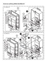
Heating system designsSystem design2D20 M152LONLONFE22K20A Vitodens 200-W (models 45 to105) with the Vitotronic <strong>100</strong>, <strong>HC1</strong>,with KMK cascade communicationmodule as part of the st<strong>and</strong>arddeliveryB Vitocontrol-S, <strong>WB2B</strong> with LONcommunication module (accessory)C DHW cylinderD Vitotronic 200-H with LONcommunication module(accessories)E Mixing valve on Vitocontrol-S,<strong>WB2B</strong>F Mixing valve on Viotronic 200-HH Low loss header1431464040LONLON! Outdoor temperature sensor? Supply temperature sensorcommon heating flow(low loss header)?M1 Supply temperature sensormixing valve circuit 1 -extended circuit(Vitotronic 200-H)?M2/M3Supply temperature sensormixing valve circuit 2 or 3(Vitocontrol-S)% DHW temperature sensorsÖ Boiler pump (Vitotronic <strong>100</strong>,<strong>HC1</strong>)sÖM1 Mixing valve circuit 1(Vitotronic 200-H)sÖM2/M3Mixing valve circuit 2 or 3(Vitocontrol-S)sA DHW pumpsK DHW recirculation pumpfÖ Power supply, 120 V/60 HzgSM1 Motor mixing valve circuit 1(Vitotronic 200-H)gSM2/M3Motor mixing valve circuit 2or 3 (Vitocontrol-S)aVD/aVH External hook-up(Vitocontrol-S),see page 22.aVG/KMK Connection toVitotronic <strong>100</strong>, <strong>HC1</strong> toVitocontrol-SKMK Interconnection betweenboiler controls <strong>and</strong> Vitotronic<strong>100</strong>, <strong>HC1</strong>5414 553 v1.4M2 M32 20 52 2 20 522B128521145A AE205252KMK2PPMPPMKMK2020 2052HC8
Heating system designsSystem design (cont.)The codes must be set on every Vitotronic <strong>100</strong>.(see section on coding page 82)Vitotronic <strong>100</strong>, <strong>HC1</strong>Required coding01 : 2 Multi-boiler system with Vitocontrol-S, <strong>WB2B</strong>07 : 207 : 307 : 4Setting the boiler number at the Vitotronic <strong>100</strong> of thesecond boilerthird boilerfourth boilerVitocontrol-S, <strong>WB2B</strong>Required coding00 : 3,00 : 4,00 : 7,or00 : 835 : 135 : 235 : 335 : 4Heating circuit M2 without DHW heatingHeating circuit M2 with DHW heatingHeating circuit M2 <strong>and</strong> M3 without DHW heatingHeating circuit M2 <strong>and</strong> M3 with DHW heatingSetting up Vitocontrol-S withone Vitotronic <strong>100</strong>two Vitotronic <strong>100</strong>three Vitotronic <strong>100</strong>four Vitotronic <strong>100</strong>Vitotronic 200-H (if installed)Required coding97 : 1 The outdoor temperature is accepted by the LON BUS5414 553 v1.49
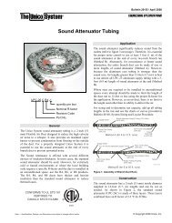
Heating system designsSystem design (cont.)Multiple (up to four) Vitodens 200-W, models <strong>WB2B</strong> 45, 60, 80 <strong>and</strong>d 105 with...– multiple heating circuits with mixing valves– low-loss headerVitocontrol-SPPM PPM PPM PPMBoiler 1 Boiler 2 Boiler 3 Boiler 4TPVPRV PRV PRV PRVCommonSupplyTemperatureSensor M MDHW TankLow-LossHeaderFig. 31When designing a multiple Vitodens system as shown above, please reference applicable multiple Vitodens technicaldocumentation, <strong>and</strong> contact your local Viessmann Sales Representative for further assistance.IMPORTANTThis installation example depicts apossible piping layout for multipleVitodens 200-W, <strong>WB2B</strong> boilersequipped with Viessmann systemTechnology. Please note that thisexample is based on a simplifiedconceptual drawing only! Piping <strong>and</strong>necessary componentry must be fieldverified.A low water cut-off (LWCO) must beinstalled where required by local codes.Proper installation <strong>and</strong> functionality inthe field is the responsibility of theheating contractor.WARNINGWhen extending wire, there is thepossibility of exposure toelectromagnetic interference.Avoid running wires beside or nearhigh voltage 120/240 VACconductors. If proximity to highvoltage conductors cannot beavoided, use str<strong>and</strong>ed, twisted pair orshield design wire. Ensure that onlyone end of the shielding is grounded.5414 553 v1.410
<strong>Installation</strong> – Vitocontrol-S, <strong>WB2B</strong>Installing the Cascade Communication ModuleAThe cascade communication module2.<strong>Installation</strong> Instructions shippedwith boiler.A3.1.X7AB1453 2 1CCD5414 553 v1.4A Vitocontrol-S <strong>WB2B</strong>B KMK-BUSC Boiler control with Vitotronic <strong>100</strong><strong>and</strong> KMK Module (max 4 boilers)D 2-core Cable(cable cross-section 2 x 0.5 mm 2total length 164ft. / 50m)E Plug aVG into the Vitocontrol-S<strong>WB2B</strong>F Terminal strip ”KMK1/KMK2” atthe cascade communication moduleof the boiler control withVitotronic <strong>100</strong>1 2 3 4KMK1 KMK21 2 3 4KMK1 KMK2Note:The total length of BUS cables Bshould not exceed 164ft. / 50m.The wires from the BUS cables arecommutable.11
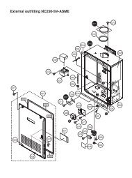
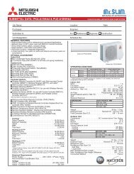
<strong>Installation</strong> – Vitocontrol-S, <strong>WB2B</strong>Summary of electrical connections (Power Pump Module)MAIN POWER SUPPLY120V, 60HZ, 12AN G LPower/Pump module1 2 31431 2 31441 2 3145<strong>Installation</strong>Instructions,Power PumpModuleLOW WATER CUT-OFFSAFETY DEVICE-TYPICALL2L1P1P2AL2 L1 G NL N4040L N20A20AL N2121L N2020L N5050L28G N1431441451 2 3 1 2 3 1 2 3M120VACBOILERPUMP120VACFAULTALARMOUTPUT20 L N 40145X 7X47 6 5 4 3 2 1X3<strong>100</strong>35209640230 VACX 8X9Boiler Control BoardX11LONKMK5414 553 v1.4MAINDISCONNECTSWITCH120VACWALLRECEPTACLE120/230TransformerKMK1KMK2X11 2 3 4KMKModule12
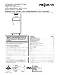
<strong>Installation</strong> – Vitocontrol-S, <strong>WB2B</strong>Summary of electrical connectionsLON5252202022M3M2M3M2M3M2 145145152/3143146282129205040156A15414 553 v1.4Mixing valve extension circuit board?M2/M3 Supply temperature sensorsÖM2/M3 Heating circuit pumpgSM2/M3 Mixing valve actuatorLow voltage motherboard! Outdoor temperature sensor? Common supply temperaturesensor% DHW tank temperature sensoraVD External connectionaVG Connection to Vitotronic <strong>100</strong>(KMK Module) <strong>and</strong> Vitotrolremote controlaVHLONConnection for external dem<strong>and</strong>LON BUS, interconnecting cablefor data transfer betweenVitocontrol-S <strong>and</strong>Vitotronic 200-H orVitocom 300Line voltage motherboardsÖ Heating circuit pump (hightemperature space heating)sA DHW pumpsK DHW re-circulation pumpfÖ Power supply connectiongÖ Compiled failure alarmaBH Internal power supply for mixingvalve extension circuit board <strong>and</strong>connections for accessoriessL Not used (no function)13
<strong>Installation</strong> – Vitocontrol-S, <strong>WB2B</strong>Summary of electrical connections (continued)29Vitocontrol-S <strong>WB2B</strong>6295414 553 v1.414
<strong>Installation</strong> – Vitocontrol-S, <strong>WB2B</strong>Mounting of the control unit1.1.Fasten metal backplate ontomounting surface with fourfasteners.2.3.2.Position midplate between backplate<strong>and</strong> connection enclosure.3.Install midplate <strong>and</strong> connectionenclosure onto backplate.4.Fasten connection enclosure <strong>and</strong>midplate onto backplate with twofasteners.5.Install control rear section ontoconnection enclosure housing. Hookcontrol onto backplate tabs <strong>and</strong>pivot downwards.4.6.Fasten control rear section ontoconnection enclosure with twofasteners.5.6.5414 553 v1.415
<strong>Installation</strong> – Vitocontrol-S, <strong>WB2B</strong>Inserting cables <strong>and</strong> applying strain reliefRun the cables from the connection enclosure into the control unit.Apply strain relief to cables (see below).Cables with moulded strain reliefclampConnect cable <strong>and</strong> strain relief clamp.ORFasten cable to the cable lead withcable tie.5414 553 v1.416
<strong>Installation</strong> – Vitocontrol-S, <strong>WB2B</strong>Sensor connection15 21 2 31 2 3 1 2 3A B CAOutdoor temperature sensor(not polarity sensitive)BDHW tank temperature sensorCSupply temperature sensor –common heating supply<strong>Installation</strong> location:North or north-western wall. Inmulti-storey buildings, in the upperhalf of the second floor.Not above windows, doors orventilation outlets.Not immediately below balcony orgutter.Do not paint over.Connection:Two-wire cable, max. 120ft. / 35mlength, AWG 16.5414 553 v1.417
<strong>Installation</strong> – Vitocontrol-S, <strong>WB2B</strong>Sensor connection (continued)Outdoor temperature sensorThe outdoor temperature sensor should be mounted 6.5 to 8ft / 2 to 2.5m aboveground level on the north or north-west facing wall of the building. In the case ofmulti-storey buildings, it should be mounted in the upper half of the second storey.Make sure that the sensor is not located over windows, doors <strong>and</strong> air vents, norimmediately beneath a balcony or guttering.Do not paint over the outdoor temperature sensor housing.1. Remove the cap.2. Mount the bottom part of the sensorhousing.1.5.3.3. Pull the sensor wire through theopening in the terminal compartment<strong>and</strong> through the strain reliefprovided.4. Connect the wires to the terminals.5. Place the cap over the outdoortemperature sensor.4.6005802.560540WARNINGWhen extending wire, there is thepossibility of exposure toelectromagnetic interference.Avoid running wires beside or near highvoltage 120/240 VAC conductors. Ifproximity to high voltage conductorscannot be avoided, use str<strong>and</strong>ed,twisted pair or shield design wire.Ensure that only one end of theshielding is grounded.Resistance in520500480460440420400-40 -30 -20 -10 0 10 20 30-40 -22 -4 14 32 50 68 86Outdoor temperature in °C / °F5414 553 v1.418
<strong>Installation</strong> – Vitocontrol-S, <strong>WB2B</strong>Sensor connection (continued)DHW tank temperature sensorThe sensor measures the domestic hotwater tank temperature.Heating systems with domestic hotwater heating (single-boiler systemsonly)1. Install the DHW tank temperaturesensor.Check the sensor1. Disconnect plug % in the terminalcompartment of the boiler control.2. Measure resistance of sensor atterminals ”1” <strong>and</strong> ”2” of the plug.5Resistance in720700680660640See installation instructionsfor domestic hot water tankNote:When installing the sensor in DHWtanks of other makes, make surethat the sensor is pressed againstthe sensor well of the DHW tank bymeans of a suitable device.2. Ensure that the maximumpermissible domestic hot watertemperature is not exceeded. Ifnecessary, install a suitable safetydevice for this purpose.DHW tanktemperaturein °F / °C /104 / 40122 / 50140 / 60Resistancein Ω5785976163. Compare the value measured withthe current temperature. If the valuediffers significantly, checkinstallation <strong>and</strong>, if necessary, replacesensor.Technical dataDegree of protection: IP 32Ambient temperatureDuring operation:32 to + 194°F0 to + 90°CDuring storage <strong>and</strong> transport:- 4 to + 158°F-20 to + 170°CElectrical connectionThe sensors are ready to plug in. Insertthe DHW temperature sensor in socket”5” of the boiler control.620600580Heating systems without domestic hotwater heatingDo not connect the DHW tanktemperature sensor.5605414 553 v1.45400 20 40 60 80 <strong>100</strong>32 68 104 140 176 212DHW tank temperature in °C / °F19
<strong>Installation</strong> – Vitocontrol-S, <strong>WB2B</strong>Connection of the pumpsAvailable pump connectionssÖ Heating circuit high temperature(without mixing valve)sÖM2 Heating circuit M2 pumpTerminals 2 - L, - G , - NsÖM3 Heating circuit M3 pumpTerminals 1 - L, - G , - NTERMINAL4 or 3AsAsKDHW pump for heating up thedomestic hot water tank -Terminals 4 - L, - G , - NDHW recirulation pumpTerminals 3 - L, - G, - N.BInstall pumps: seemanufacturer’sinstructions.120 VAC pumpsNote:The maximum power consumption ofall pumps is 4A .Rated current: max. 2 FLARecommended connectioncable: AWG 14Connect the 3-wire cable from thepump to the corresponding terminals.240 VAC or 3 PH pumpsNote:Use contactor to switch pump.For activating the contactor:Rated current: max. 2 FLARecommended connectioncable: AWG 14Please ensure that all connections <strong>and</strong>cable gauge comply with local <strong>and</strong>national codes.1.Select the contactor <strong>and</strong> theconnecting cable in accordance withthe rating of the pump that is to beconnected.2.Connect the pump <strong>and</strong> power supplyto the contactor.3.Connect contactor coil to thecorresponding terminals.5414 553 v1.420
<strong>Installation</strong> – Vitocontrol-S, <strong>WB2B</strong>Connection of modulating valve actuatorsControl unit1 120V or 24V valve adaptor2 DIN rail in connection enclosure3 aBH Terminals120V Valve AdaptorRated voltage: 120 VACRated current: max. 0.1 FLARecommended connectionwire size: AWG 1424V Valve AdaptorRated voltage: 24 VACRated current: max. 0.15 FLARecommended connectionwire size: AWG 14Operating time:5 to 199 sec. selected via codingaddress “40”.1 120V valve adaptor2 120V valve actuator1 24V valve adaptor2 24V valve actuator1. Disconnect power to control.2. Install 120V or 24V valve adaptoron DIN rail inside connectionenclosure.3. Insert the plug gS into socket gS onthe control.4. Fasten cable with tie.5. Connect black wire of the adaptor toconnection aBH on the DIN rail- Terminal 8,9 or 10.6. Connect valve actuator wires to theadaptor terminals as shown onfigures.5414 553 v1.421
<strong>Installation</strong> – Vitocontrol-S, <strong>WB2B</strong>Connection of external contacts143 146ABCDry Contacts:A External heating programchangeover/external“Mix.valve open”B External blocking/external“Mix.valve closed”C External dem<strong>and</strong>A External heating programchangeover or ”Mix.valve open”Contact closed:The manually pre-selected heatingprogram can be modified via thiscontact, (see table below) enabling themixing valves to be opened.The “Mix.valve open” function can beallocated via coding address “9A”, <strong>and</strong>the heating program changeover can beallocated to the heating circuits viacoding address “91”.B External disable/external“Mix.valve close”Closing the zero volt contact causesthe burner to shut down or the mixerto be closed.Allocated boiler circuit pumps areswitched OFF <strong>and</strong> shut-off valves areclosed.WARNINGHeating circuits are no longer frostprotected during “Mix.valve close”. Alower boiler water temperature is notmaintained during external blocking.Via coding address “99”, you c<strong>and</strong>etermine what input aVD shouldaffect.C External dem<strong>and</strong>Closing the dry contact starts the boilerburners of the individual boilers subjectto load via a set supply temperature(coding address “9b”) on Vitocontrol-S,<strong>WB2B</strong>.The supply temperature is limited viathe set min. <strong>and</strong> max. supplytemperature.Manually pre-selectedheating program(with open contact)9orworRoom heating OFF/DHW OFFRoom heating OFF/DHW ONrw Room heating ON/DHW ONCoding 2d5: 0(factorydefault)Changed heating program(with closed contact) Continuous operation with reduced room temperature/DHW OFFd5: 1 Continuous operation with normal room temperature/DHW inaccordance with coding address “64”5414 553 v1.422
<strong>Installation</strong> – Vitocontrol-S, <strong>WB2B</strong>Connection of the compiled failure alarmARated voltage: 120 VAC 60 HzRated current:max. 2 FLARecommended connectionwire size: AWG 141. Disconnect power to control <strong>and</strong>burner.2. Connect the compiled failure alarmas shown in the diagram.A Connect terminal strip inconnection enclosure of boilercontrolB Visual <strong>and</strong>/or audible alarm device(120 VAC)B5414 553 v1.423
<strong>Installation</strong> – Vitocontrol-S, <strong>WB2B</strong>Making the LON connectionThe Viessmann LON system is designed for the Line BUS topology with end of line resistors on both ends.Connection with Viessmann LON cableA A AC23ft. / 7m23ft. / 7mCBBA Control unit or VitocomB LON cableC End of line resistorConnection with Viessmann LON cable <strong>and</strong> Viessmann LON couplingA A AC23ft. / 7m 23ft. / 7m 23ft. / 7m 23ft. / 7m 23ft. / 7m 23ft. / 7mCBDBDBB BBD DA Control unit or VitocomB LON cable (max. 3 cablesbetween two devices)C End of line resistorD LON extension jack,5414 553 v1.424
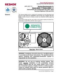
<strong>Installation</strong> – Vitocontrol-S, <strong>WB2B</strong>Making the LON connection (continued)Connection withViessmann LON cable,On-site cable for extensions up to 900 m / 3000 ft.A A AC23ft. / 7mE E EE23ft. / 7m 23ft. / 7m 23ft. / 7mCB B B BFmax. 900 m / 3000 ft.DA Control unit or VitocomB LON cableC End of line resistor (st<strong>and</strong>arddelivery of Vitocontrol-S, <strong>WB2B</strong>)D Up to 99 participants <strong>and</strong> thecorresponding number of junctionboxes <strong>and</strong> cablesE Junction boxF Connecting cable (on site)Note:The Viessmann LON system alwaysrequires two conductors <strong>and</strong> shielding.Conductors are interchangeable.Observe the requirements for cabling<strong>and</strong> operation of the LON interfaceFTT-10A (see www.echelon.com).Power supply1. Ensure that the main power supplyto the control contains overcurrentprotection with a minimum rating of6A <strong>and</strong> 2-pole disconnect5414 553 v1.4LegendL: LineN: NeutralG: GroundA Power supply 120 VAC, 1PH,60Hz, provide disconnect means<strong>and</strong> overcurrent protection as perlocal codesB Terminal fÖ in connectionenclosureC Connection enclosureWARNINGThe control must be grounded.Ensure that “L”, “N” <strong>and</strong> “G” are notinterchanged.2. Connect power supply wire to theconnection fÖ terminals 11, N <strong>and</strong> Gon the DIN rail inside the connectionenclosure.25
<strong>Installation</strong> – Vitocontrol-S, <strong>WB2B</strong>Installing the control unit front1.1. Position the front part of the housing<strong>and</strong> clip hinges to counter-parts onmain housing.8.7.2. Release the stay bar, open it up<strong>and</strong> lock in position.3. Insert the flat cable from theOptolink into plug ”X20”.4. Insert the plug of the programmingunit into plug ”X10”. Use cableguides in cover for routing.5. Engage the stay bar in the fronthousing.6.6. Close the front of the housing.7. Secure front housing with suppliedscrews.8. Install cover of the connectionenclosure <strong>and</strong> support with suppliedscrew.2.5.3.4.5414 553 v1.426
<strong>Installation</strong> – Vitocontrol-S, <strong>WB2B</strong>Opening the control unit1. Unscrew the screws from the fronthousing.2. Swing up the front part of thecontrol housing.3. Position the stay bar so that itsupports the front housing.2.1.3.5414 553 v1.427
Initial start-upSteps. . . . . . . . . . . . . . . . . . . . . . . . . . . . . . . . . . . . . . . . . . . . . . . . . . . . . . . . . . . . . . . . . . . . . . . . . . . . . . . . . . . . . . . . . . . . . . . . . . . . . . . . . . . . . . . . . . . . . . . . . . . . . . . . . . . . . . . . . . . . . . . . . . . . . . . . . . . . . . . . . . . . . . . . . . . . . . . . . . . . . . . . . . . . . . . . . . . . . . . . . . . . . . . . . . . . . . . . . . . . . . . . . . . . . . . . . . . . . . . . . .1. Commissioning all Vitodens 200-W with Vitotronic <strong>100</strong>Vitodens 200-W Service Instructions . . . . . . . . . . . . . . . . . . . . . . . . . . . . . . . . . . . . . . . . . . . . . . . . . . . . . . . . . . . . . . . . . . . . . . . . . . . . . . . . . . . . . . . . . . . . . . . . . . . . . . . . . . . . . . . . . . . . . . . . . . . . . . . . . . . . . . . . . . . . . . . . . . . . . . . . 29.Page2. Controls <strong>and</strong> display elements Vitotronic <strong>100</strong>, <strong>HC1</strong> . . . . . . . . . . . . . . . . . . . . . . . . . . . . . . . . . . . . . . . . . . . . . . . . . . . . . . . . . . . . . . . . . . . . . . . . . . . . . . . . . . . . . . . . . . . . . . . . . . . . . . . . . . . . . . . . . . . . . . . . . . . . . . . . . . . . . . . . . . . . . . . . . . . . . . . . . . . . . . . . . . . . . . . . . . . . . . . . . . . . . . . . . . . . . . . . . . 29 Vitocontrol-S, <strong>WB2B</strong> . . . . . . . . . . . . . . . . . . . . . . . . . . . . . . . . . . . . . . . . . . . . . . . . . . . . . . . . . . . . . . . . . . . . . . . . . . . . . . . . . . . . . . . . . . . . . . . . . . . . . . . . . . . . . . . . . . . . . . . . . . . . . . . . . . . . . . . . . . . . . . . . . . . . . . . . . . . . . . . . . . . . . . . . . . . . . . . . . . . . . . . . . . . . . . . . . 303. Checking the heating circuit allocation (Vitocontrol-S, <strong>WB2B</strong>) . . . . . . . . . . . . . . . . . . . . . . . . . . . . . . . . . . . . . . . . . . . . . . . . . . . . . . . . . . . . . . . . . . . . . . . . . . . . . . . . . . . . . . . . . . . . . . . . . . . . . . . . . . . . . . . . . . . 304. Changing the display language (Vitocontrol-S, <strong>WB2B</strong> if required) . . . . . . . . . . . . . . . . . . . . . . . . . . . . . . . . . . . . . . . . . . . . . . . . . . . . . . . . . . . . . . . . . . . . . . . . . . . . . . . . . . . . . . . . . . . . . . . . . . . . . . . . . . . . 305. Configuring a multi-boiler system . . . . . . . . . . . . . . . . . . . . . . . . . . . . . . . . . . . . . . . . . . . . . . . . . . . . . . . . . . . . . . . . . . . . . . . . . . . . . . . . . . . . . . . . . . . . . . . . . . . . . . . . . . . . . . . . . . . . . . . . . . . . . . . . . . . . . . . . . . . . . . . . . . . . . . . . . . . . . . . . . . . . . . . . . . . . 316. Connecting control units into the LON system . . . . . . . . . . . . . . . . . . . . . . . . . . . . . . . . . . . . . . . . . . . . . . . . . . . . . . . . . . . . . . . . . . . . . . . . . . . . . . . . . . . . . . . . . . . . . . . . . . . . . . . . . . . . . . . . . . . . . . . . . . . . . . . . . . . . . . . . . . . . . . . . . . 327. Carrying out a participant check (Vitocontrol-S, <strong>WB2B</strong>) . . . . . . . . . . . . . . . . . . . . . . . . . . . . . . . . . . . . . . . . . . . . . . . . . . . . . . . . . . . . . . . . . . . . . . . . . . . . . . . . . . . . . . . . . . . . . . . . . . . . . . . . . . . . . . . . . . . . . . . . . . . . . . . 328. Reducing the maximum burner output . . . . . . . . . . . . . . . . . . . . . . . . . . . . . . . . . . . . . . . . . . . . . . . . . . . . . . . . . . . . . . . . . . . . . . . . . . . . . . . . . . . . . . . . . . . . . . . . . . . . . . . . . . . . . . . . . . . . . . . . . . . . . . . . . . . . . . . . . . . . . . . . . . . . . . . . . . . . . . . . . . 339. Matching the coding addresses to the system version . . . . . . . . . . . . . . . . . . . . . . . . . . . . . . . . . . . . . . . . . . . . . . . . . . . . . . . . . . . . . . . . . . . . . . . . . . . . . . . . . . . . . . . . . . . . . . . . . . . . . . . . . . . . . . . . . . . . . . . . . . . . . . . . . . 3310. Checking outputs (actuators) <strong>and</strong> sensors . . . . . . . . . . . . . . . . . . . . . . . . . . . . . . . . . . . . . . . . . . . . . . . . . . . . . . . . . . . . . . . . . . . . . . . . . . . . . . . . . . . . . . . . . . . . . . . . . . . . . . . . . . . . . . . . . . . . . . . . . . . . . . . . . . . . . . . . . . . . . . . . . . . . . . . 3411. Selecting the boiler sequence (Vitocontrol-S, <strong>WB2B</strong>) . . . . . . . . . . . . . . . . . . . . . . . . . . . . . . . . . . . . . . . . . . . . . . . . . . . . . . . . . . . . . . . . . . . . . . . . . . . . . . . . . . . . . . . . . . . . . . . . . . . . . . . . . . . . . . . . . . . . . . . . . . . . . . . . . . 3512. Adjusting the heating curve (Vitocontrol-S, <strong>WB2B</strong>) . . . . . . . . . . . . . . . . . . . . . . . . . . . . . . . . . . . . . . . . . . . . . . . . . . . . . . . . . . . . . . . . . . . . . . . . . . . . . . . . . . . . . . . . . . . . . . . . . . . . . . . . . . . . . . . . . . . . . . . . . . . . . . . . . . . . . 365414 553 v1.428
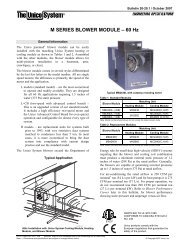
Initial start-upFurther step-by-step instructionsCommissioning of all Vitodens 200-W, <strong>WB2B</strong> with Vitotronic <strong>100</strong>, <strong>HC1</strong>Service Instructions Vitodens 200-W, <strong>WB2B</strong>AºC+OKiKHGFED CBA Heating programsB No functionC InformationD Fact0ory default settingE ConfirmationF Value settingG No functionH Emissions test functionK Boiler water temperature5414 553 v1.429
Initial start-upFurther step-by-step instructions (continued)Boiler sequenceA Heating circuit selectionB Reduced room temperatureC DHW temperatureD Normal room temperatureE St<strong>and</strong>by modeF DHW onlyG Heating <strong>and</strong> DHWH Economy modeK Party modeL InformationM St<strong>and</strong>ard settingsN ConfirmationO Adjusting valuesP Time programsR Holiday programS Time/dateT Heating curve level shiftU Heating curve slopeChecking the heating circuit allocation (Vitocontrol-S, <strong>WB2B</strong>) Check that the label for heatingcircuit allocation has been affixed tothe corresponding fields of theprogramming unit. Press the corresponding key beforecommencing all adjustments.Changing the display language (Vitocontrol-S, <strong>WB2B</strong>)1. Press i.3. Confirm with .2. Select the required languagewith .5414 553 v1.430
Initial start-upFurther step-by-step instructions (continued)The cascade communication module must be fitted into all Vitotronic <strong>100</strong> boiler control.Setting codes, see page 82 <strong>and</strong> 88.Example of a multi-boiler systemVitocontrol-S Vitotronic <strong>100</strong> Vitotronic <strong>100</strong>145KMK1KMK2KMK1Vitocontrol-S, <strong>WB2B</strong> Vitotronic <strong>100</strong>, <strong>HC1</strong> – – – – Vitocontrol-S, <strong>WB2B</strong>–– Multi-boiler systemSet code ”01:2”–– Boiler number 1Coding ”07:1”Number of connected boilers< 5 boilersSet code ”35:2”, ”35:3” or”35:4”Connecting control units into the LON systemThe LON communication module (accessories) must be fitted.Note:The data transfer via the LON system can take several minutes.Vitotronic 200-H– – – – Multi-boiler systemSet code ”01:2”Boiler number 4Set code ”07:4”–– ––Setting up LON participant numbersIn coding 1, set the LON participantnumber via coding address “77”.<strong>Installation</strong> <strong>and</strong> serviceinstructions, Vitotronic 200-H.Note:In one LON system, each numbermust only be allocated once.Vitocontrol-S, <strong>WB2B</strong>1. Set the number of boilersIn coding 1, set coding address “35”.Coding 1 see page 84.Note:In one LON system, each numbermust only be allocated once.Only one Vitotronic may beprogrammed as fault manager.5414 553 v1.431
Initial start-upFurther step-by-step instructions (continued)Update the LON particiapant list on Vitocontrol-S, <strong>WB2B</strong>Only possible if all users are connected <strong>and</strong> the control unit is encoded as fault manager (coding 79 : 1 factory defaultsetting)Note:In each heating system, only one Vitotronic may be encoded as fault manager.1. Press w <strong>and</strong> simultaneouslyfor approx. 2 s.The participant check is initiated.2. Press D.The participant list is updatedafter approx. 2 min.Participant check completed.Example of a LON systemVitocontrol-S Vitotronic 200-H Vitotronic 200-HVitocomLONLONLONParticipant no. 5Code ”77:5”Participant no. 10Set code ”77:10”Participant no. 11Set code ”77:11”Participant no. 99Send time via LONCode ”7b:1”Accept time via LONSet code ”81:3”Accept time via LONSet code ”81:3”Time received via LONTransmit outdoor temperaturevia LONSet code ”97:2”Receive outdoor temperaturevia LONSet code ”97:1”Device receives the timeCarrying out a participant checkThe communication with the system devices connected to the fault manager is tested by means of a participant check.Preconditions: The control unit must be programmed as fault manager (code 79:1). The LON participant number must be programmed in all control units(see page 31). The fault manager participant list must be up to date.Participant checkF01 : 011Consecutivenumber in theparticipant listParticipantnumber1. Press w <strong>and</strong> simultaneously forapprox. 2 seconds.2. Select the required participant with<strong>and</strong> .3. Activate check with .”Check” flashes until its completion.The display <strong>and</strong> all key illuminationsof the selected participant flash forapprox. 60 seconds. During communication betweenboth devices ”Check OK” isdisplayed. ”Check not OK” is displayed, if nocommunication is established.Check the LON connection <strong>and</strong>coding.4. To check further participantsproceed as described under points 2<strong>and</strong> 3.5. Press w <strong>and</strong> simultaneously forapprox. 1 second.5414 553 v1.432
Initial start-upFurther step-by-step instructions (continued)Reducing the maximum burner output (Vitotronic <strong>100</strong>)Vitodens 200 service instructionsMatching coding addresses to respective system versionVitotronic <strong>100</strong>In code 1, set the following codingaddresses:01 Multi-boiler system06 Maximum boiler07 Boiler number2F Air bleed functionIn code 2, set the following codingaddresses:76:2 With cascade communicationmodule KMKMatching coding addresses to respective system versionVitocontrol-S, <strong>WB2B</strong>In code 1, set the following codingaddresses:00 System design35 Number of boilers in cascade36 Minimum limit of the cascadesupply temperature37 Maximum limit of the cascadesupply temperature3b Control type3C Control strategy77 LON participant number *1A2 DHW priorityA5 Heating circuit pump logicfunction (economy control)C5 Minimum supply temperaturelimit, heating circuitsC6 Maximum supply temperaturelimit, heating circuitsIn code 2, set the following codingaddresses:38 Lead boiler rotation39 Permanent lead boiler3A Permanent last boiler55 Function DHW temperaturecontrol78 LON communication enabled7A Central control7F Detached house or apartmentbuilding98 Viessmann system number *1*1 Only in conjunction with LON system5414 553 v1.433
Initial start-upFurther step-by-step instructions (continued)Checking outputs (actuators) <strong>and</strong> sensorsVitotronic <strong>100</strong>Relay test1. Press 9 <strong>and</strong> simultaneously forapprox. two seconds.2. Select the relay outputswith or .3. Press .The following relay outputs may be selected:DisplayindicationRelay function11Burner modulation lower output12Burner modulation upper output13Internal pump/ output 20 ON (Power Pump module)14Output 50 ON/ fault indicator in Power Pump ModuleCheck sensors1. Press .Scanning operating conditions isactive, see page 41.2. Scan the actual temperature withor .3. Press .Scanning is completed.5414 553 v1.434
Initial start-upFurther step-by-step instructions (continued)Vitocontrol-S, <strong>WB2B</strong>Relay test1. Press 9 <strong>and</strong> simultaneously forapprox. two seconds.2. Select the relay outputswith or .3. Press .The following relay outputs may be selected:Output 20M1 ONOutput 52A1 openOutput 52A1 ntr.Output 52A1 closeDHW tank heating pump ONDHW recirculation pump ONHeating pump (M2) ONHeating pump (M3) ONMixing valve (M2) openMixing valve (M2) closeMixing valve (M3) openMixing valve (M3) closeCentral fault display ONNote:The illuminated heating circuit selectorbutton indicates the correspondingheating circuit.Check sensors1. Press .Scanning operating conditions isactive, see page 46.2. Scan the actual temperature withor .3. Press .Scanning is completed.Selecting the boiler sequence (Vitocontrol-S, <strong>WB2B</strong>)1. If required:In coding 2, set coding addresses 39(permanent lead boiler) <strong>and</strong> 3A(permanent last boiler).2. Press <strong>and</strong> simultaneously forapprox. two seconds.3. Select the required boiler sequencewith or .By pressing <strong>and</strong>simultaneously, you can exit theadjustment without saving anymodifications made.4. Press .The adjustment has beentransferred.5. In coding 2, set the codingaddresses 38, 41, 42, 43 <strong>and</strong> 44;see also the function descriptionfrom page 62.5414 553 v1.435
Initial start-upFurther step-by-step instructions (continued)Adjusting the heating curve (Vitocontrol-S, <strong>WB2B</strong>)The heating curves illustrate the relationship between the outdoor temperature <strong>and</strong> the boiler water or the supplytemperature. To put it simply: the lower the outdoor temperature, the higher the boiler water or supply temperature. Theroom temperature again depends on the boiler water or the supply temperature.Factory default settings:Slope: = 1.4Shift: = 0Generally, the heating curve is set:In range A for underfloor heating systems,In range B for low temperature heating systems (according to the Energy Savings Order),Slope3.43.23.02.8Supply tempertaure in ºC / ºF2.62.490/19480/17670/15860/14050/12240/1041.81.61.41.21.00.830/860.63595308625772068105015591050Set room temperature in ºC / ºF541541032-523-1014-155-20-4Outdoor temperature in ºC / ºF0.40.25414 553 v1.436
Initial start-upFurther step-by-step instructions (continued)Changing slope <strong>and</strong> shift(for every heating circuit separately)1. Call up slope with ,adjustable value 0.2 to 3.5;call up shift with ;adjustable value 8.6 to 104°F / –13to +40°C.2. Change the value with or .3. Confirm the set value with .1102303.5Supply temperature in °C / °FAB1.40.2+20 / 68 -20 / -4A Change slopeB Change shift5414 553 v1.4Outdoor temperature in °C / °F37
Initial start-upFurther step-by-step instructions (continued)Adjusting the normal room temperature(for every heating circuit separately)123St<strong>and</strong>ard room temp.20Normal room temperature:Select the normal day temperature withthe set value adjuster.The value will be automaticallytransferred after approx. 2 seconds.123Reduced room temp.14Reduced room temperature:1. Call up the reduced nighttemperature with tm.2. Change the value with or .3. Confirm the set value with .Temperature conversion:D E D E˚F˚C-4 -2041 557 1468 2079 26230 110Example 1:Adjustment of the normal roomtemperature from 68 to 79˚F / 20 to26˚C.Example 2:Adjustment of the reduced roomtemperature from 41 to 57˚F / 5 to14˚C.A Boiler water temperature or supplytemperature in ˚F / ˚CB Outdoor temperature in ˚F / ˚CC Set room temperature in ˚F / ˚CD Heating circuit pump OFFE Heating circuit pump ONAccordingly, the heating curve isadjusted along the set room temperatureaxis, resulting in modified start/shutdowncharacteristics for the heating circuitpumps, if the heating circuit pump logicis active.5414 553 v1.438
Service scanning – Vitotronic <strong>100</strong>, <strong>HC1</strong>Service level summaryFunction Entry Exit PageReducing the max.burner outputRelay testTemperatures,boiler coding card<strong>and</strong> brief scansPress 9 <strong>and</strong> twsimultaneously forapprox. 2 secondsPress 9 <strong>and</strong> “OK”simultaneously forapprox. 2 secondsPress 9 <strong>and</strong> rwsimultaneously forapprox. 2 secondsPress “OK” 32Press “OK” 35Press “OK” 35OperatingPress 8 Press 8 46conditionsTroubleshooting Press “OK” 47Fault historyResetting codesto the factorydefault settingCoding Level 1Coding Level 2Press rw <strong>and</strong> “OK”simultaneously forapprox. 2 secondsPress w <strong>and</strong> rwsimultaneously forapprox. 2 secondspress DPress 9 <strong>and</strong> wsimultaneously forapprox. 2 secondsPress w <strong>and</strong> rwsimultaneously for approx.2 secondsVitodens 200-W Service InstructionsPress “OK” 47–– 82Press 9 <strong>and</strong> wsimultaneously forapprox. 1 secondPress w <strong>and</strong> rwsimultaneously forapprox. 1 second81825414 553 v1.439
Service scanning – Vitotronic <strong>100</strong>, <strong>HC1</strong>Temperatures, boiler coding card <strong>and</strong> quick scans1. Press 9 <strong>and</strong> rw simultaneouslyfor approx. two seconds.2. Select the required scanwith or .Brief scans8 8 8 8 8 80 Systemdesign 1Control unit software versionProgrammingunit softwareversion1 Burner control unit softwareversionENo function3 Set boiler temperatureAHighest dem<strong>and</strong> temperature4 Burner control unit type Boiler type5 No functionb Maximum heating output in %CBoiler coding card (hexadecimal)Cascademodulesoftwareversionc Equipment version (EEPROM) Burner control unit version(EEPROM)dVariable speedpump0 without1 Wilo2 GrundfosVariable speedpump softwareversion5414 553 v1.440
Service scanning – Vitotronic <strong>100</strong>, <strong>HC1</strong>Scanning operating conditions1. Press 8. 2. Select the required operatingcondition scan with or .3. Press .ScansDisplayindicationExplanationNotes0 01Boiler number ––3__65263572030417°C Boiler temperature ––h Burner hours run The hours run can be reset to 0 with D.The hours run displayed are onlyapproximate values.h Burner starts The burner starts can be reset to 0 withD.5414 553 v1.441
Service scanning – Vitotronic <strong>100</strong>, <strong>HC1</strong>Scanning <strong>and</strong> resetting service displaysAfter the limits set up via coding addresses 21 <strong>and</strong> 23 (see page 82) have been reached, the programming unit displayflashes one of the following messages.Note:Set code 24:1 <strong>and</strong> then code 24:0, if maintenance is implemented before a maintenance message is displayed; the setmaintenance parameters for hours run <strong>and</strong> maintenance intervals are then reset to 0.Displayindication35510 h___12 uExplanationBurner run hours havebeen reachedTime interval(e.g. 12 months)has been reached1. Scan maintenance messages withor .2. Press .The maintenance indication in thedisplay is cleared.Note:An acknowledged maintenancemessage can be redisplayed bypressing (approx. three seconds).After maintenance has been carried out1. Reset coding 24: 1 (see page 82) to24: 0.Note:If coding address 24 is not reset, anew maintenance message will bedisplayed on Monday morning.2. If required:PressReset burner run hours <strong>and</strong> burnerstarts with D(see page 82)Press5414 553 v1.442
Service scans – Vitocontrol-S, <strong>WB2B</strong>Service level summaryFunction Entry Exit PageAdjusting displaycontrastParticipant checkRelay testBoiler sequenceTemperatures <strong>and</strong>quick scansPress the “OK” <strong>and</strong> “+”buttons simultaneously;the display will darkenPress the “OK” <strong>and</strong> “-” buttonssimultaneously;the display will get lighterPress the w <strong>and</strong> “OK” buttonssimultaneously for approx.2 secondsPress the 9 <strong>and</strong> “OK” buttonssimultaneously for approx. 2secondsPress the g <strong>and</strong> û buttonssimultaneously for approx. 2secondsPress 9 <strong>and</strong> rwsimultaneously for approx. 2seconds–– –––– ––Press the w <strong>and</strong> “OK” buttons simultaneously for approx. 1 sec 32Press the “OK” button 35Press the “OK” button 35Press the “OK” button 44Operating status Press the i button Press the i button 46Troubleshooting Press the i button Press the “OK” button 51Error historyResetting codingsto factory defaultsettingsCoding Level 1Coding Level 2Press the rw <strong>and</strong> “OK”buttons simultaneously forapprox. 2 secondsPress the w <strong>and</strong> rw buttonssimultaneously for approx.2 seconds; press the D button;confirm by pressing the “OK”buttonPress 9 <strong>and</strong> w simultaneouslyfor approx. 2 secondsPress the w <strong>and</strong> rw buttonssimultaneously for approx. 2seconds; confirm by pressing the“OK” buttonPress the “OK” button 51–– 81Press the 9 <strong>and</strong> w buttons simultaneously for approx. 1 sec 81Press the w <strong>and</strong> rw buttons simultaneously for approx. 1 sec 825414 553 v1.443
Service scans – Vitocontrol-S, <strong>WB2B</strong>Temperatures <strong>and</strong> quick scans1. Press 9 <strong>and</strong> rw simultaneouslyfor approx. 2 seconds.3. Press “OK”.2. Select the required scanwith or .The following values can be scanned subject to the actual equipment level:Outdoor temperature adjustedOutdoor temperature actualBoiler sequenceP-actual % boiler 1 to 4Output red. %IntegralBoiler temperature actual boiler . . . .1 to 4Sensor 17B actual (not used)Set DHW temperatureActual DHW temperatureSupply temperature setSupply temperature actualRoom temperature setRoomtemperature actualQuick scan 1 to quick scan 8The adjusted outdoor temperaturecan be reset to the current outdoortemperature with D.Boiler output - actual value.No function.at - 1 to - <strong>100</strong> start-up integral inpercent; at 1 to <strong>100</strong> shutdownintegral in percent ( - arrow aboveword, when integral grows).Display only if a sensor is connected.Display only if a system design witha DHW tankhas been encoded . . . . .(code 00).Display only if a remote control unitis installedQuick scans 1 to 7, see page 45.5414 553 v1.444
5414 553 v1.4Scan123Scan88Display acc. tosystem designs (see codingaddress 00)Software versioncontrol unitOperating modesys. circuit A10 w/o remotecontrol1 withVitotrol 2002 withVitotrol 300Software versionprogrammingunitSoftware versionremote controlsystem circuitA1N/A8Software versionmixing valveextension M2Printed CircuitBoardOperating modemixing valvecircuit M20 w/o remotecontrol1 withVitotrol 2002 withVitotrol 3008Number of KMBUSparticipantsN/ASoftware versionremote controlmixing valvecircuit M2N/A8Software versionmixing valveextension M3Printed CircuitBoardOperating modemixing valvecircuit M30 w/o remotecontrol1 withVitotrol 2002 withVitotrol 300N/A8Software versionremote controlmixing valvecircuit M3Temperatures <strong>and</strong> quick scans (continued)45678LON participant numberSNVTSoftware versionconfiguration communication0 = Auto co-processor1 = ToolDevice identificationhexa-decimal: b8 / decimal: 184N/AN/AN/ASubnet address/system numberSoftware versionneuron chipN/AN/AN/ANode addressNumber ofLON participantsN/AN/AMaximum system design temperatureService scans – Vitocontrol-S, <strong>WB2B</strong>45
Service scans – Vitocontrol-S, <strong>WB2B</strong>Scanning operating conditions1. Press .3. Press .2. Select the required scanwith or .The following values can be scanned subject to the actual equipment level:Participant numberHoliday program with departure <strong>and</strong>return dateHoliday program activeOutdoor temperatureBoiler sequenceCommon supply temperatureBoiler temp. 1 to 4Sensor 17B (not used)DHW temperatureSupply temperatureReturn temperatureRoom temperatureTimeDateOutput 20 ON/OFFOutput 29 ON/OFFOutput 52 open/closeDHW tank heating pump ON/OFFDHW recirculation pump ON/OFFHeating pump ON/OFFMixing valve open/closedLanguagesIf a holiday program has been enteredIf a central holiday program is activeActual value boilers 1 to 4Display only if a sensor is connectedDisplay only if a DHW tank sensor isconnectedDisplay only in conjunction withmixing valve circuitsDisplay only if a remote control unitis installedPosition detail in %Position detail in %.Each language can be selected aspermanent display languagewith5414 553 v1.446
Troubleshooting – Vitotronic <strong>100</strong>, <strong>HC1</strong>Faults displayed at the programming unitThe red faults indicator U flashes forevery fault.A fault code flashes in the display if afault message has been issued (seepage 47).i Consecutive fault number38 Fault codeU Fault symbolA fault can be acknowledged with“OK”. The fault message in the displaywill be hidden, but the red faultindicator U continues to flash.The fault message will be redisplayed,if an acknowledged fault message hasnot been removed by the followingmorning.Calling up acknowledged faultmessagesPress “OK” for approximately 2seconds.Select the acknowledged fault withor .Call up further fault codes with.orE in the display indicates that theburner control unit is locked out. Afterthe fault has been removed,acknowledge by pressing reset E.Note:After acknowledging the fault, E willbe displayed until the burner controlunit lockout has been lifted.Retrieving fault codes from the fault memory (fault history)The most recent 10 faults are saved <strong>and</strong> may be called up.Faults are sorted by date. The most recent fault is fault number 1.1. Press rw <strong>and</strong> simultaneouslyfor approx. 2 seconds.2. Press or for individual faultcodes.Note:All saved fault codes can be deletedwith D.3. Press to finish scan.5414 553 v1.447
Troubleshooting – Vitotronic <strong>100</strong>, <strong>HC1</strong>Faults displayed at the programming unit (continued)FaultcodeSystem characteristics Cause Remedy0fControl mode Service “0F” is only displayed in thefault history30Burner blocked Boiler water temperature sensorshorted outService the equipment.Note:After the service, reset codingaddress “24” to “0”.Check the boiler water temperaturesensor38Boiler water temperature sensorcable brokenb0b1b4b5Control mode (stays in factorydefault setting)regulates as if the outdoortemperature was 32°F / 0°CControl mode(factory default setting)Flue gas temperature sensorshorted out.Communication fault -programming unit (internal)Internal faultb7Burner blocked Boiler coding card missing, faulty orincorrect boiler coding card.b8Flue gas temperature sensor cablebroken.Check the flue gas temperaturesensor (see Vitodens 200-WStart-up/Service Instructions).Check connections <strong>and</strong> replaceprogramming unit, if required.Replace the control unit.Plug in boiler coding card or replace,if faulty.Check the flue gas temperaturesensor (see Vitodens 200-WStart-up/Service Instructions)e4Fault, supply voltage 24V Replace the control unit.e5Internal fault Check ionization electrode <strong>and</strong>connecting cables, check tightnessof flue gas system.Press “E RESET”.e8Burner in fault mode The ionization current lies outsidethe permiss. range.e9eaThe ionization current lies outsidethe permiss. range duringcalibration.The ionization current lies outsidethe permiss. range duringcalibration.Check ionization electrode <strong>and</strong>cable. Press “E RESET”.Check ionization electrode <strong>and</strong>cable. Press “E RESET”.Check ionization electrode <strong>and</strong>cable. Press “E RESET”.5414 553 v1.448
Troubleshooting – Vitotronic <strong>100</strong>, <strong>HC1</strong>Faults displayed at the programming unit (continued)FaultcodeSystem characteristics Cause RemedyebBurner blocked Boiler control initiated a combustioncalibration but could not completethe process- Heat generated by boiler must beremoved (boiler is cycling ontemperature limits, beforecalibration process is complete)- Check the connecting cable <strong>and</strong>the ionization electrode, check theflue gas system (flue gasrecirculation).- Verify pump operation- Switching points of flow switchmarginal (not enough flow)- Check coding card- Check gas valve- Check coding address 82- Also see address 12:_Press “E RESET”.Burner in fault mode The ionization current lies outside Check ionization electrode <strong>and</strong>ecthe permiss. range duringcable. Press “E RESET”.calibration.Internal fault. Replace the control unit.edeeefAt burner start, flame signal ismissing or too week.Flame is lost immediately after ithas built (during the safety time).Check ionization electrode <strong>and</strong>cable, test ionization current, checkgas supply, check ignition <strong>and</strong>ignition module, check condensatedrain. Press “E RESET”.Check gas supply, check fluegas/exhaust pipe/air intake for fluegas recirculation, check ionizationelectrode (replace if necessary)Press “E RESET”.Burner blocked Internal fault. Replace control unit.f0Burner in a fault mode Maximum flue gas temperature Check the heating system fill level.f1exceeded (230ºF / 110ºC).Bleed air from system. Press “ERESET” after vent system hascooled down.f2f3Fixed high limit switch open(activated).Flame signal is already present atburner start.Check heating system fill level.Check the circulation pump. Bleedair from the system. Check fixedhigh limit switch <strong>and</strong> connectingcables. Press “E RESET”.Check the ionization electrode <strong>and</strong>connecting cable. Press “E RESET”.5414 553 v1.449
Troubleshooting – Vitotronic <strong>100</strong>, <strong>HC1</strong>Faults displayed at the programming unit (continued)FaultcodeSystem characteristics *1 Cause RemedyBurner in a fault mode No flame signal is present. Check ionization electrode <strong>and</strong>f4cable, measure the ionizationcurrent, check the gas pressure,check the gas valve, ignition,ignition module, ignition electrodes<strong>and</strong> condensate drain. Press “ERESET”.The gas valve closes too late. Check gas valve <strong>and</strong> both controlf8wiring <strong>and</strong> connections. Press “ERESET”.Fan speed too low at burner start. Check fan, fan supply cables, fanf9power supply <strong>and</strong> control. Press “ERESET”.Fan not at st<strong>and</strong>still. Check the fan, the fan connectingfacables <strong>and</strong> fan control. Press “ERESET”.fcGas valve faulty or faultymodulation valve control; or ventsystem blocked.Check the gas valve. check the ventsystem. Press “E RESET”.Burner blocked Burner control unit fault. Check ignition electrodes <strong>and</strong>fdconnecting cables. Check the boilercoding card. Check whether astrong interference (EMC) fieldexists near the equipment; press“E RESET”. Replace control unit ifthe fault persists.Burner blocked or in a fault mode Strong interference (EMC) field Restart the equipment. Replace thefenearby, or faulty main PCB.control unit if the equipment will notffNo faultcodedisplayedStrong interference (EMC) fieldnearby, or internal fault.restart.Boiler/burner in st<strong>and</strong>still Flow switch open Check pump operation <strong>and</strong> flowswitch.*1 Control mode: Boiler/burner fully operational (fault code must be verified <strong>and</strong> reset).Burner in fault mode: Boiler control requires manual reset before burner can resume operation.Burner blocked: If fault cause is corrected, burner resumes operation.5414 553 v1.450
Troubleshooting – Vitocontrol-S, <strong>WB2B</strong>Faults displayed at the programming unitRed fault indicator U flashes for all faults.The display flashes “Fault” if a fault message is issued.TroubleshootingOutdoor temp. sensorBDG- 1 101FaultBDG- 2 d51U Fault symbol2 Consecutive number (1 to 10)d5 Fault code (for explanations seepage 52)1. Press .2. Call up further fault codeswith or .The fault can be acknowledged with. The fault message in the displaywill be hidden, but the red faultlindicator U continues to flash. Anew fault message will be displayedif an acknowledged fault is notremoved by the following morning.A central fault messaging deviceconnected to plug gÖ will beactivated.Fault display in plain textExt. faultOutdoor temperature sensorSupply sensorDHW tank sensor (1 or 2; displayonly, if a second DHW tanktemperature sensor is connected)Return sensorRoom temperature sensorFlue gas sensorCollector sensorSolar DHW sensorParticipant numberParticipant fault (display only ifcontrol unit is programmed as faultmanager)Calling up acknowledged faultmessagesPress for approx. 2 seconds. Thefault will then be displayed.Select the acknowledged faultwith or .Retrieving fault codes from the fault memory (fault history)The most recent 10 faults are saved <strong>and</strong> may be called up.Faults are sorted by date. The most recent fault is fault number 1.Fault history1 1811. Press rw <strong>and</strong> simultaneouslyfor approx. 2 seconds.2. Call up the individual fault codeswith or3. Press .5414 553 v1.4Note:All saved fault codes can be deletedwith D.51
Troubleshooting – Vitocontrol-S, <strong>WB2B</strong>Faults displayed at the programming unitFault display in plain textExt. faultOutdoor temperature sensorSupply sensorDHW tank sensor (1 or 2; displayonly, if a second DHW tanktemperature sensor is connected)Room temperature sensorParticipant fault (display only ifcontrol unit is programmed as faultmanager)Calling up acknowledged faultmessagesPress for approx. 2 seconds. Thefault will then be displayed.Select the acknowledged faultwith or .FaultcodeSystem characteristics Cause Remedy0fControl mode Service “0F” is only displayed in thefault historyControls as if the outdoor10 temperature was 32˚F / 0˚C18Outdoor temperature sensor shortedoutOutdoor temperature sensor cablebrokenVitocontrol-S, <strong>WB2B</strong> controls in a Common supply temperature sensor20st<strong>and</strong>-alone manner w/o supply shorted outtemperature sensor (supply28 temperature may not be highCommon supply temperature sensorenough)cable brokenMixing valve closes Supply temperature sensor of40mixing valve circuit M2 shorted out44Supply temperature sensor ofmixing valve circuit M3 shorted out48Supply temperature sensor cable ofmixing valve circuit M2 broken4cSupply temperature sensor cable ofmixing valve circuit M3 brokenService the equipment.Note:After the service, reset codingaddress “24” to “0”.Check outdoor temperature sensor(see page 70)Check common supply temperaturesensor (see page 69)Check supply temperature sensor(see page 69)5414 553 v1.452
CCTroubleshooting – Vitocontrol-S, <strong>WB2B</strong>Faults displayed at the programming unit (continued)FaultcodeSystem characteristics Cause Remedy50DHW tank primary pump ON:Set DHW temp.= set boiler watertemp., priority controls are cancelledorWith DHW tank primary system:DHW heating is started <strong>and</strong> stoppedby DHW tank temp. sensor 2 (notused)51With DHW tank primary system:DHW heating is started <strong>and</strong> stoppedby DHW tank temp. sensor58DHW tank primary pump ON:Set DHW temp.= set boiler watertemp., priority controls are cancelledorWith DHW tank primary system:DHW heating is started <strong>and</strong> stoppedby DHW tank temp. sensor 2 (notused)With DHW tank primary system:59DHW heating is started <strong>and</strong> stoppedby DHW tank temp. sensorBoiler with maximum temp.,6068return control openWith DHW tank primary system:70 Mixing valve primary circuit closed,no DHW heating (not used).78DHW tank temperature sensor 1shorted outDHW tank temperature sensor 2(not used) shorted outDHW tank temperature sensor cablebrokenDHW tank temperature sensor 2(not used) cable brokenSensor incorrectly connectedTemperature sensor aJB shortedoutTemperature sensor aJB cablebrokenCheck DHW tank temp. sensorSet code “4A:0”Check temperature sensorWithout temperature sensor:Set code “4b:0”Control mode Maintenance or error on Vitotronic Check maintenance display or fault84 <strong>100</strong> of boiler 1 to 4 code on the respective Vitotronic<strong>100</strong>8586878CCommunication fault Vitotronic <strong>100</strong> Check <strong>and</strong> replace cascadeCc of boiler 1 to 4communication module of the8C - Boiler No. 1Vitotronic <strong>100</strong> <strong>and</strong> connecting8D - Boiler No. 2cable, if required8E - Boiler No. 3- check for assigned participant no.8F - Boiler No. 4 (see address 07: on page 9 <strong>and</strong> 82)- if problem persists, replace all 4modules with part no. 7441 586.8d8e8f5414 553 v1.453
Troubleshooting – Vitocontrol-S, <strong>WB2B</strong>Faults displayed at the programming unit (continued)FaultcodeSystem characteristics Cause RemedyControl mode92 Only solar control unit fault codeswill be displayed93Collector temp. sensor shorted out,connects to S1 at the VitosolicDHW tank temp. sensor shortedout, connects to S3 at the Vitosolic94Temp. sensor shorted out, connectsto S2 at the Vitosolic9a9b9c9fabControl operation perhaps DHWtank coldCollector temp. sensor cablebroken, connects to S1 at theVitosolicDHW tank temp. sensor cablebroken, connects to S3 at theVitosolicTemp. sensor cable broken,connects to S2 at the VitosolicFaultSolar control unit; displayed if afault without fault code occurs atthe solar control unitDHW tank primary systemconfiguration error:Code “55:3” has been set, but plugaJB is not plugged in (not used)<strong>and</strong>/orCodes “4C:1” <strong>and</strong> “4E:1” have notbeen setb1Control mode Communication errorProgramming unitCheck solar control unit sensorCheck solar control unitInsert plug aJB <strong>and</strong> check thecode (not used).Check connections <strong>and</strong> replaceprogramming unit if required.Emmissions test mode Internal electronics fault Check electronics PCB <strong>and</strong> replace,b4 if required.Control modeb5b6Constant mode Invalid hardware recognized Check coding address “92”(”92:186”)baMixing valve “close” Communication error mixing valveextention PCBbcbdbeControl mode without remotecontrolCommunication error Vitotrolremote control, heating circuit A1Communication error Vitotrolremote control, heating circuit M2Communication error Vitotrolremote control, heating circuit M3bfControl mode Incorrect LON communicationmoduleCheck PCB <strong>and</strong> replace, if required.Check connections, lead/cable,coding address “A0” <strong>and</strong> remotecontrol DIP switches.Replace the communication module.5414 553 v1.454
Troubleshooting – Vitocontrol-S, <strong>WB2B</strong>Faults displayed at the programming unit (continued)FaultcodeSystem characteristics Cause Remedyc2Control mode Cable break KM BUS to solarcontrol unit.c4Communication error with functionextension 0 to 10 VCheck KM BUS cable <strong>and</strong> the solarcontrol unitWithout solar control unit:Set code “54: 0”Check connections <strong>and</strong>cables/leads; replace the functionextension, if requiredWithout function extension:Set code “9d: 0”ceCommunication error Plug-inadaptor for external safetyequipmentCheck plug-in adaptor for externalsafety equipment <strong>and</strong> cables/leadsWithout plug-in adaptor:Set coding “94: 0”cfErrorLON communication moduleReplace communication moduled6Fault at DE1 in plug-in adaptor forexternal safety equipment (notused)Check connections at “DE1” to“DE3”d7Fault at DE2 in plug-in adaptor forexternal safety equipment (notused)d8Fault at DE3 in plug-in adaptor forexternal safety equipment (notused)daControl mode without roominfluenceRoom temperature sensor shortedout,Heating circuit A1Check room temperature sensordbRoom temperature sensor shortedout,Heating circuit M2dcRoom temperature sensor shortedout,Heating circuit M3ddRoom temperature sensor cablebroken,Heating circuit A1Check the room temperature sensor<strong>and</strong> the DIP switch on the VitotroldeRoom temperature sensor ablebroken,Heating circuit M2dfRoom temperature sensor cablebroken,Heating circuit M35414 553 v1.455
Troubleshooting – Vitocontrol-S, <strong>WB2B</strong>Faults displayed at the programming unit (continued)LON participants fault messagesParticipantPreconditions:The control unit must be programmedas fault manager (code “79:1”)12Faultcode01to98System characteristics Cause RemedyControl mode A participant, e.g. 12(Vitotronic 200-H), hasdeveloped a faultorThere is no connection to theparticipant99Fault message active atVitocom 300orFault at the Vitocom 300orNo connection to the Vitocom300Download fault code to participantSee the <strong>Installation</strong> <strong>and</strong> Service instructionsof the relevant control unit.- Check coding- Check LON communication module- Update participant list- Carry out a participant checkCheck external connections at Vitocom 300See separate <strong>Installation</strong> <strong>and</strong> Serviceinstructions- Check coding- Check LON connection cable- Update participant list- Carry out a participant check5414 553 v1.456
Function description – Vitotronic <strong>100</strong>, <strong>HC1</strong>Boiler temperature controlBrief descriptionThe boiler water temperature isregulated by controlling a modulatingburner.The set boiler water temperatureset-point is controlled by Vitocontrol-S,<strong>WB2B</strong>.Coding addresses which influence theboiler temperature control06 (see page 82).For a description, see the codingoverview.FunctionsThe boiler water temperature isrecorded separately:Fixed high limit (FHL)Boiler temperature sensor KTS(changes in resistance NTC)Upper control limit.Electronic maximum limitSetting range: 20 to boiler coding carddefaultThe maximum boiler water temperaturelimit can be adjusted via codingaddress 06.Control sequenceBoiler goes cold(set value 4ºC below set point)The burner start signal is set to the setboiler water temperature less (=less7.2ºF or 4ºC) <strong>and</strong> the burner starts itsown monitoring program.Boiler heats up.The burner shutdown point isdetermined by the switch-offdifferential of (=less 14.4ºF or 8ºC)above set point.Note:Value on display shown in K (Kelvin).1 K = 1.8 Fahrenheit degrees or 1Celsius degree.Air bleed programNote:Close the gas shut-off valve whenoperating the air bleed program.The air bleed program is activated viacoding address 2F:1 (the display showsEL).During the air bleed program, thecirculation pump will be alternatelyswitched ON <strong>and</strong> OFF for 30 secondsrespectively over a period of 20minutes.The burner is switched OFF during theair bleed program.The program is automaticallydeactivated after 20 minutes, <strong>and</strong> thecoding address is set to 0.5414 553 v1.457
Function description – Vitocontrol-S, <strong>WB2B</strong>Cascade control unitBrief descriptionThe supply temperature is regulated bystarting or stopping the burner or bystarting/stopping individual burners.The boilers will be controlled to the setboiler water temperature determined bythe cascade control (st<strong>and</strong>-alone typeof control).Subject to the system design, you mayselect between one gross calorificstrategy <strong>and</strong> two net calorificstrategies.The boiler sequence (see page 62) canbe determined via coding 2 <strong>and</strong> theboiler sequence selection.Coding addresses which influence thecascade control35 to 3F, 41 to 4F.For a description, see the codingoverview.Set supply temperatureThe set supply temperature isdetermined fromthe set supply temperature set-pointvalues of system circuit A1 <strong>and</strong>mixing valve circuits M2 <strong>and</strong> M3,the set supply temperature values ofadditional heating circuits (e.g.Vitotronic 200-H),the set DHW temperature <strong>and</strong>external dem<strong>and</strong>s (e.g. the setsupply temperature defaulted bycoding address 9b or via the InputModule 0 to 10 V).Upper control limitElectronic maximum system supplytemperature limit.Setting range: 68 to 261˚F / 20 to127˚C.The maximum supply temperature limitcan be adjusted via coding address 37.This value must be set no higher thanthe lowest value of coding address 06of all connected Vitotronic <strong>100</strong>, <strong>HC1</strong>.Lower control range limitElectronic minimum system supplytemperature limit.Setting range: 68 to 261˚F / 20 to127˚C.The minimum supply temperature limitcan be adjusted via coding address 36.5414 553 v1.458
Function description – Vitocontrol-S, <strong>WB2B</strong>Cascade control (continued)Control sequenceSt<strong>and</strong>-alone type of control: Parallel boiler control(coding 3b : 0 without supply temperature sensor orcoding 3b : 1 with supply temperature sensor)The cascade control unit defaults theset boiler water temperature to allcurrently active boilers.Every Vitotronic <strong>100</strong> individuallyregulates the dafaulted settemperature.The control sequence is subject to thestart-up <strong>and</strong> shutdown criteria selectedwith control strategy (coding address3C):Gross calorific strategy.Net calorific strategy 1.Net calorific strategy 2.Without supply temperature sensor:The control deviation is calculated fromthe set boiler water temperature <strong>and</strong>the estimated average actual boilerwater temperture of the active boiler todetermine the start-up <strong>and</strong> shutdowncriteria. Only those boilers are takeninto consideration whose boiler circuitpumps are not switched OFF.With supply temperature sensor:The contro deviation is calculated fromthe set supply temperature <strong>and</strong> theactual supply temperature to determinethe start-up <strong>and</strong> shutdown criteria.Gross calorific strategy (Condensing strategy)It is the aim of the gross calorificstrategy to operate as many boilers aspossible at the lowest output(modulation) level.Start-up criterionBoilers are started via an outputstatement (coding 3d : 1).An additional boiler will be startedwhen the currently required output canalso be achieved by the currently activeboiler plus the next boiler in the boilersequence (see page 69).AdvantagesOptimum utilization of thecondensing effect (as many boilersactive as possible)Long burner operating timesShutdown criterionThe boiler is shut down via a shutdownintegral. The shutdown criterion is metwhen the shutdown integral exceeds alimit set via coding address 46, <strong>and</strong> theboiler started last will be shut down.5414 553 v1.459
Function description – Vitocontrol-S, <strong>WB2B</strong>Cascade control (continued)Net calorific strategy 1Conventional boilers are preferablyoperated at their upper output range, toreliably prevent the formation ofcondensate due to low returntemperatures.With net calorific strategy 1, anadditional boiler will only be started ifthe maximum output of all currentlyactive burners is insufficient to achievethe set supply temperature.A boiler will be shut down, when theremaining boiler(s) can achieve therequired output on its/their own.Benefit:As few boilers as possible are active.Start-up criteriaThe boiler is started via a start-upintegral.The start-up criteria is met when thestart-up integral exceeds a limit set viacoding address 45, <strong>and</strong> the next boilerin the sequence will be started (seepage 62).Shutdown criteriaThe boiler is shut down via an outputstatement (coding 3d: 1).A boiler is shut down when thecurrently required output can beachieved without the boiler which wasstarted last.Net calorific strategy 2With the net calorific strategy 2, anadditional boiler will only be started ifthe maximum output of all currentlyactive burners is insufficient to achievethe set supply temperature.A boiler will be shut down if the burnerwas returned to its minimum outputbecause of a large negative controldeviation, <strong>and</strong> the output is then stilltoo high.Benefit:Long burner operating timesStart-up criteriaThe boiler is started via a start-upintegral.The start-up criteria is met when thestart-up integral exceeds a limit set viacoding address 45, <strong>and</strong> the next boilerin the sequence will be started (seepage 62).Shutdown criteriaThe boiler is shut down via a shutdownintegral. The shutdown criteria is metwhen the shutdown integral exceeds alimit set via coding 46, <strong>and</strong> the boilerstarted last will be shut down.5414 553 v1.460
Function description – Vitocontrol-S, <strong>WB2B</strong>Cascade control (continued)Control strategy exampleTwo boiler system with modulating burners <strong>and</strong> separate flue gas systems:Boiler 1: <strong>100</strong>% rated output (basic load set to 25%)Boiler 2: <strong>100</strong>% rated output (basic load set to 25%)Gross calorific strategy (coding 3C: 0)Start-upSwitching OFFRated output in %Total Boiler 2 Boiler 1<strong>100</strong>66250<strong>100</strong>250200150<strong>100</strong>Rated output in %Total Boiler 2 Boiler 1<strong>100</strong>66250<strong>100</strong>250200150<strong>100</strong>250Time250TimeNet calorific strategy 1 (coding 3C: 1)Start-upSwitching OFFRated output in %Total Boiler 2 Boiler 1<strong>100</strong>50250<strong>100</strong>500200150<strong>100</strong>Rated output in %Total Boiler 2 Boiler 1<strong>100</strong>502505414 553 v1.4<strong>100</strong>500200150<strong>100</strong>250Time250Time61
Function description – Vitocontrol-S, <strong>WB2B</strong>Cascade control (continued)Net calorific strategy 2 (coding 3C: 2)Start-upSwitching OFFRated output in %Total Boiler 2 Boiler 1<strong>100</strong>50250<strong>100</strong>500200150<strong>100</strong>Rated output in %Total Boiler 2 Boiler 1<strong>100</strong>66250<strong>100</strong>250TimeBoiler sequenceThe boiler sequence is determined bythe boiler sequence selection <strong>and</strong> thefollowing coding addresses (see alsopage 88):38 Changing the lead boiler <strong>and</strong> theboiler sequence.38: 1 Every 1 st day of themonth, the boiler with theburner which hasoperated for the shortestnumber of hours becomeslead boiler.38: 2 After 200 to 20,000 runhours, the boiler with thenext higher number(coding address 07 ofVitotronic <strong>100</strong>) becomeslead boiler.39 Boiler 1, 2, 3 or 4 permanent leadboiler.3A Boiler 1, 2, 3 or 4 permanent lastboiler.41 ECO threshold boiler 1.42 ECO threshold boiler 2.43 ECO threshold boiler 3.44 ECO threshold boiler 4.Via the ECO threshold, every boiler canbe disabled or enabled subject to theoutdoor temperature. The ECO controlbecomes disabled, if the boiler isrequired to achieve the set supplytemperature, when enabled boilershave failed. At least the lead boilerremains active if all boilers in a systemare disabled by the ECO control.5414 553 v1.4250200150<strong>100</strong>250Time62
Function description – Vitocontrol-S, <strong>WB2B</strong>Heating circuit controlBrief descriptionThe control unit provides controlcircuits for one high temperature(boiler) circuit <strong>and</strong> two mixing valvecircuits.The set supply temperature of everyheating circuit results from the outdoortemperature, the set room temperature,the operating mode <strong>and</strong> the heatingcurve.The supply temperature of the systemcircuit corresponds to the commonsystem supply temperature.The supply temperature of the mixingvalve circuits is regulated by thestepped opening or closing of themixing valves.The mixing motor control changes theactuating <strong>and</strong> pause times subject tothe control difference(control deviation).Coding addresses which influence theheating circuit control9F,A2 to A7, A9, C3 to C8, F1, F2For a description, see the codingoverview.Time programThe control unit timer changes inaccordance with the times programmedin the room heating <strong>and</strong> DHW heatingprogram between the heating withnormal room temperature <strong>and</strong> heatingwith reduced room temperatureoperating modes.Every operating mode has its own setlevel.Outdoor temperatureA heating curve must be set up formatching the control unit to thebuilding <strong>and</strong> the heating system.The heating curve characteristicsdetermine the set boiler watertemperature subject to outdoortemperature. An average outdoortemperature (dampened) is used forcontrol purposes. This comprises theactual <strong>and</strong> the adjusted outdoortemperature.FunctionsThe high temperature (boiler) circuit issubject to the boiler water temperature<strong>and</strong> its control range limits.The heating circuit pump is thecontrolling element. The mixing valvecircuit supply temperature is recordedby the supply temperature sensor.5414 553 v1.463
Function description – Vitocontrol-S, <strong>WB2B</strong>Heating circuit control (continued)Domestic hot water temperatureWith priority control:The set supply temperature will beset to 32˚F / 0˚C during DHWheating.The mixing valve closes, <strong>and</strong> theheating circuit pumps are switchedOFF.Without priority control:The heating circuit control unitcontinues to operate with the sameset value.Room temperatureIn conjunction with remote control <strong>and</strong>room temperature input (observecoding address b0).Compared to the outdoor temperature,the room temperature has a greaterinfluence on the common set supplytemperature. This influence may beadjusted via coding address b2.In conjunction with the mixing valvecircuit:For control differences (actual valuedeviation) above 3.6˚F / 2˚C roomtemperature, the influence can beincreased again (via coding address b6,quick heat-up/quick setback).Quick heat-up:The set room temperature must beraised by a minimum of 3.6˚F / 2˚Cby:Pressing party button .Changing from heating with reducedtemperature to heating with normaltemperature.Start-up optimisation.Quick heat-up will stop when the setroom temperature has been reached.Quick setback:The set room temperature must bereduced by a minimum of 3.6˚F / 2˚Cby:Pressing economy button .Changing from room heating withnormal temperature to heating withreduced temperature.Shutdown optimisation.Quick setback will stop when the setroom temperature has been reached.Heating circuit pump logic(economy circuit)The heating circuit pump is switchedOFF (set supply temperature set to 0˚C /32˚F), when the outdoor temperatureexceeds the value selected via codingaddress A5.Extended economy circuitThe heating circuit pump is switchedOFF, <strong>and</strong> the set supply temperature isset to 32˚F / 0˚C, if:The outdoor temperature exceeds thevalue selected via coding address A6.The set room temperature is reducedvia coding address A9.In conjunction with the mixing valvecircuit:The mixing valve has been closed for12 minutes (mixing valve economyfunction, coding address A7).Slab curing function(only in conjunction with a mixing valvecircuit).Please note:Four different temperature profiles canbe selected for drying the slab. Theseprofiles are activated via codingaddress F1.When the slab curing function isactivated, the heating circuit pump ofthe mixing valve circuit is switchedON, <strong>and</strong> the supply temperature will beheld at the selected profile. Aftercompletion (30 days), the mixing valvecircuit will be regulated automaticallyvia the set parameters.System dynamics – mixing valve circuit(only in conjunction with a mixing valvecircuit)You can influence the controlcharacteristics of the mixing valve viacoding address C4.Central operationCentral operation for all downstreamheating circuits can be programmed viacoding address 7A.The heating <strong>and</strong> holiday program thenapplies to all heating circuits in thesystem.The programming unit of the otherheating circuits displays central controlwhen the heating program <strong>and</strong> holidayprogram buttons are activated.Any set holiday programs in theheating circuit programming units willbe deleted.Party <strong>and</strong> economy buttons on allcontrol units are without effect.Frost protectionWhen the outdoor temperature fallsbelow 34˚F / 1˚C, a supplytemperature of at least 50˚F / 10˚Cwill be safeguarded.For changes, see coding address A3,variable frost limit.5414 553 v1.464
Function description – Vitocontrol-S, <strong>WB2B</strong>Heating circuit control (continued)Supply temperature controlDifferential temperature:The differential temperature may beadjusted via coding address 9F; factorysupplied setting 15˚F / 8˚C.The differential temperature is thatminimum temperature differential bywhich the common supply temperatureshould be higher than the currentlyrequired supply temperature of themixing valve circuit.System with only one mixing valvecircuit:The common set supply temperaturewill be automatically held 15˚F / 8˚Cabove the set supply temperature ofthe mixing valve circuits.System with high temperature(boiler) circuits <strong>and</strong> mixing valvecircuits:The common set supply temperatureoperates in accordance with its ownheating curve. The differentialtemperature of 15˚F / 8˚C towardsthe set supply temperature of themixing valve circuits is set up at thefactory.Upper control limitElectronic maximum limit:Setting range: 34 to 261˚F / 1 to127˚C.Changes via coding address C6.Please note:The maximum limit is no replacementfor the underfloor heating systemtemperature limiter.Supply temperature °C / °F+8K110230871898K+20/ 68 -20/-4Outdoor temperature in °C / °FA Max. common supply temperatureB Slope = 1.8 high temperature(boiler) circuitC Slope = 1.2 mixing valve circuitD Common supply temperature (at adifferential temperature = 15˚F /8˚C)E Minimum common supplytemperatureLower control range limitElectronic minimum limit:Setting range: 34 to 261˚F / 1 to127˚C.Changes via coding address C5 (onlyeffective in st<strong>and</strong>ard mode).5414 553 v1.4Control sequenceMixing valve circuitThe mixing valve motor will not beactivated within the neutral zone(±2˚F / 1˚C).Supply temperature falls(set value -2˚F / –1˚C)The mixing valve motor receives theopen signal.The signal duration lengthens with anincreasing control differential. Theduration of pauses reduces with anincreasing control differential.Supply temperature rises(set value +2˚F / 1˚C)The mixing valve motor receives theclose signal.The signal duration lengthens with anincreasing control differential. Theduration of pauses reduces with anincreasing control differential.65
Function description – Vitocontrol-S, <strong>WB2B</strong>DHW tank temperature controlBrief descriptionThe DHW tank control logic is aset-point control. It is the result ofstarting <strong>and</strong> stopping the DHW pump.The switching differential is ±4.5˚F /2.5˚C.FunctionsTime programAn automatic program or an individualtime program may be selected for DHWheating <strong>and</strong> the control of the DHWrecirculation pump.Compared with the space heatingcircuit’s heat-up phase, DHW heatingin automatic mode starts 30 minutesearlier.The individual time program enables upto four switching periods per day to beset via the time switch to control theDHW heating/heating <strong>and</strong> the DHWrecirculation pump.Any DHW tank heating sequence willbe completed, independent of the timeprogram.During DHW tank heating, a constantboiler supply temperature will be set(36˚F / 20˚C higher than the set DHWtank temperature, adjustable via codingaddress 60) <strong>and</strong> space heating isswitched OFF (optional DHW tankpriority).In conjunction with coding address 7F7F: 1 Detached house:Automatic mode:For systems with two or three spaceheating circuits, the heating times forthe first of the existing heatingcircuits will be applied.Individual time program:The switching times for DHW heating<strong>and</strong> the DHW recirculation pumphave the same effect on all heatingcircuits.Coding addresses which influence theDHW tank control54 to 75, 7F, A2.For a description, see the codingoverview.7F : 0 Apartment building:Automatic mode:For systems with two or threeheating circuits, the heating timesfor the respective heating circuitwill be applied.Individual time program:The switching times for DHW heatingcan be adjusted separately for eachheating circuit.DHW priorityWith DHW priority (coding A2: 2):The set supply temperature will beset to 32˚F / 0˚C while the DHWtank is being heated.The mixing valve closes, <strong>and</strong> theheating circuit pumps are switchedOFF.With DHW priority:The heating circuit control unitcontinues to operate with the sameset value.Frost protectionThe DHW tank will be heated to 68˚F /20˚C, if the DHW temperature fallsbelow 41˚F / 5˚C.Auxiliary functions – DHW heatingThis function is activated by providinga second set DHW temperature viacoding address 58 <strong>and</strong> activating the4 th DHW phase for DHW heating.Set DHW temperatureThe set DHW temperature can beadjusted between 50 <strong>and</strong> 140˚F / 10<strong>and</strong> 60˚C. The set range can beexp<strong>and</strong>ed to 203˚F / 95˚C via codingaddress 56.You can select the set DHWtemperature at the programming unit ofthe control <strong>and</strong> at every Vitotrol 300remote control unit (if installed).You can determine the allocation toindividual heating circuits via codingaddress 66.DHW recirculation pumpIt delivers hot water to the draw-offpoints at adjustable times. Up to fourcontrol periods can be set at the timer.Auxiliary circuitsThe DHW heating can be disabled orenabled by changing over the heatingprogram.System with DHW tank heating systemThe above functions also apply inconjunction with calorifiers.Set the following codings:4C: 1, 4E: 1, 55: 3.For a description, see the codingoverview.Systems with VitosolicA third DHW temperature set-point canbe programmed via coding address 67.Reloading suppression will be activebelow the set temperature. The DHWtank is heated only by the solar heatingsystem.5414 553 v1.466
Function description – Vitocontrol-S, <strong>WB2B</strong>DHW tank temperature control (continued)Control sequencePump delayThe DHW pump continuous operation(coding 62: 10) after the DHW tankheating, until:– the actual temperature is 9˚F / 5˚Chigher than the set DHWtemperature or– the maximum time delay (adjustablevia coding address 62) has beenreached.Without the pump time-delay forDHW tank heating (coding 62: 0).Coding 55: 0:DHW heatingThe DHW tank goes cold(set value 4.5˚F / –2.5 ˚C, adjustablevia coding address 59)The common supply temperature isadjusted 36˚F / 20˚C higher than theset DHW (adjustable via coding address60).The DHW tank is hot(set value +4.5˚F / 2.5˚C)The common set supply temperature isreturned to the weather-compensatedvalue.Coding 55: 1:Adaptive DHW tank heatingWith adaptive DHW tank heating, thespeed of the temperature rise duringDHW heating is taken into account.Also taken into account is the questionof whether the boiler will be required tosupply heat after the DHW tank hasbeen heated or whether residual boilerheat should be transferred to the DHWtank.Accordingly, the control unitdetermines the burner <strong>and</strong> DHWrecirculation pump shutdown point toprevent the set DHW temperaturebeing substantially exceeded after theDHW tank has been heated.Coding 55: 2:DHW tank temperature control with2 DHW tank temperature sensorsThe 1 st DHW tank temperature sensorenables the DHW pump, <strong>and</strong> isevaluated for stop conditions duringthe pump run-on time. The 2 nd DHWtank temperature sensor (inside thecold water inlet) is designed toprematurely start DHW tank heatingwhen large quantities of DHW aredrawn off as well as to prematurelystop DHW tank heating if no DHW isdrawn.Coding 55: 3:DHW tank control – DHW heating (forDHW loading systems only)The DHW tank goes cold(set value -4.5˚F / –2.5˚C, adjustablevia coding address 59), The common set supply temperatureis adjusted 36˚F / 20˚C higher thanthe set DHW temperature (adjustablevia coding address 60). The primary DHW pump is switchedON. The three-way mixing valve opens<strong>and</strong> then regulates to the defaultedset value. The DHW pump cycles (short termON <strong>and</strong> OFF) until the set supplytemperature has been reached, thenit runs constantly. If, during DHWtank heating, the actual value staysbelow the required set supplytemperature, then the DHW pumpwill temporarily cycle again.The DHW tank is hot(1 st DHW tank temperature sensor:Actual value ≥ set value<strong>and</strong>2 nd DHW tank temperature sensor:Actual value > set value -2.7˚F /–1.5˚C) The common set supply temperatureis returned to the weathercompensatedvalue; The DHW pump:– is immediately switched OFF, if thethree-way mixing valve is openor– is switched OFF after run-on timeadjustable via coding 62.5414 553 v1.467
Components – Vitocontrol-S, <strong>WB2B</strong>Components from the parts listThe main PCB comprises:Relays <strong>and</strong> outputs for controlling .pumps <strong>and</strong> actuators.Slot for power supply unit.Main PCB low voltageThe main PCB comprises:Connection plug for sensors,communication connections <strong>and</strong>external connections.Slot for PCB, LON communicationmodule, programming unit <strong>and</strong>Optolink PCB.Supplementary PCBWhen replacing the PCB:1. Record the coding <strong>and</strong> adjustmentsmade at the control unit.2. Replace the PCB.3. Set coding 8A: 176, <strong>and</strong> codingaddress 92 to 92: 184.Mixing valve extension PCBThe PCB comprises the relay for thecontrolling the mixing valve motor <strong>and</strong>the heating circuit pump of the mixingvalve circuits.Mixing valve extensionsupplementary PCBThis is plugged into the mixing valveextension PCB.All data is processed <strong>and</strong> outputs(relay) are selected.Power supply unit PCBThe power supply unit PCB comprisesthe low voltage supply for all electronicequipment.Programming unitSetting the:Heating programSet valuesSwitching timesHeating curve (slope <strong>and</strong> shift)DateTimeEconomy <strong>and</strong> party modeCodingDisplaying:TemperaturesOperating conditionsFaultsOptolink / override test switchPCBThe PCB comprises:Burner st<strong>and</strong>by displayFault displayOptolink laptop interfaceOverride switchOverride switch for testing flue gaswith briefly raised boiler watertemperature.The following functions are triggered inposition h:Starting all pumps.Mixing valve in control function.Front panel with heating circuitselector keysDisplay <strong>and</strong> selection of the heatingcircuit.Programming unit ON / OFFswitchThe programming unit comprises:FuseMains ON / OFF switch.FusesF1: 6.3 A (slow), 250 V,max. power loss 2.5 W,to protect the actuators, pumps, <strong>and</strong>all electronics.LON communication modulePCB for data exchange with:Vitotronic 200-HVitocom 300The communication interruption will bedisplayed.5414 553 v1.468
Components – Vitocontrol-S, <strong>WB2B</strong>Components from the parts list (continued)DHW tank temperature sensorResistance in7207006806606406206005805605400 20 40 60 80 <strong>100</strong>32 68 104 140 176 212DHW tank temperature in °C / °FConnectionSee page 17.Check sensor1. Remove plug %.2. Check the sensor resistance of theplug at terminals 1 <strong>and</strong> 2 or 2 <strong>and</strong> 3(if a second DHW tank temperaturesensor has been connected).DHW tanktemperaturein ˚F / ˚C104 / 40122 / 50140 / 60Resistance in Ω5785976163. Compare measurement with theactual temperature displayed (forscanning, see page 44).Check the installation <strong>and</strong> replacesensor, if necessary, in case ofsevere deviation.SpecificationProtection: IP 32Permiss. ambienttemperature:During operation:32 to 194˚F0 to +90˚CDuring storage <strong>and</strong> transport:–4 to 158˚F–20 to +70˚CCommon supply temperaturesensor (Low-loss header)Resistance in760740720700680660640620ConnectionSee page 17.Check sensor1.Remove plug ?.2.Check the sensor resistance of theplug at terminals 1 <strong>and</strong> 2.3.Compare measurement with theactual temperature displayed (forscanning, see page 44).Check the installation <strong>and</strong> replacesensor, if necessary, in case ofsevere deviation.SpecificationProtection: IP 32Permiss. ambienttemperature:During operation:32 to 212˚F0 to +<strong>100</strong>˚CDuring storage <strong>and</strong> transport:–4 to 158˚F–20 to +70˚C5414 553 v1.4600580560540032206840 60 80 <strong>100</strong> 120 140104 141 176 212 248 284Flow or return temperature in °C / °F69
Components – Vitocontrol-S, <strong>WB2B</strong>Components from the parts list (continued)Outdoor temperature sensorConnectionSee page 17.Check sensor1. Remove plug !.1.5.3.2. Check the sensor resistance atterminals 1 <strong>and</strong> 2 of the plug.Outdoortemperature in˚F / ˚CResistancein Ω14 / -1032 / 068 / 204805005466004.2.3. Disconnect cores from the sensor, ifactual values deviate severely fromthe curve, repeat the sensormeasurement <strong>and</strong> compare with theactual temperature (for scanning,see page 44).4. Depending on the result, replacecable or outdoor temperature sensor.5805. Scan actual temperature (forscanning, see page 44).560540520SpecificationProtection: IP 43Permissible ambient temperatureduring operation, storage <strong>and</strong>transport:–40 to 158˚F–40 to +70˚C500480460Resistance in440420400-40 -30 -20 -10 0 10 20 30-40 -22 -4 14 32 50 68 865414 553 v1.470Outdoor temperature in °C / °F
Components – Vitocontrol-S, <strong>WB2B</strong>Mixing valve circuit extension kitMixing valve motorA Plug in the mixing valve motor| Mixing valve motor open~ Mixing valve motor closeChanging the rotational directionRemove the cover <strong>and</strong> reinsert 3-poleplug A turned by 180˚.TestThe relay test of the control unit movesthe mixing valve to open <strong>and</strong> close.Manual mixing motor adjustmentLift the motorized lever up,unhook the mixing valve h<strong>and</strong>le <strong>and</strong>remove plug A.SpecificationRated voltage: 120 VAC~Rated frequency: 60 HzPower consumption: 4 WProtection: IP 42Torque:3 NmRun time fromclose to open: 120 sec5414 553 v1.4For 24V actuators pleaserefer to instructions suppliedwith the actuator.71
Components – Vitocontrol-S, <strong>WB2B</strong><strong>Installation</strong> examplesMixing valve insert conversion (if required), see mixing valve installation instructions.Factory suppliedMixing valve motor rotational directionHVChange the mixing valve motor rotationaldirection for these installation examplesHVKVHRHRKVKRKVKRKVKRHVHVKRHRHRHRHRHVKRKRHVKVKVHVHVHRHRKVKVHR Heating returnHV Heating supplyKR Boiler returnKV Boiler supply5414 553 v1.472
Components – Vitocontrol-S, <strong>WB2B</strong>Remote controlVitotrol 200(with integral room temperature sensor for room temperature feed-back in conjunction with a mixing valve circuit)Setting of:Day temperatureHeating programEconomy <strong>and</strong> party modeFunction changes can be made via coding addresses A0, b0 to b9, C0 to C2, E1, E2 (see coding overview).Connection2-wire cable 164ft. / 50mARoom temperature sensor connectionTwo-wire cable, max. 115 ft. / 35 mlength with a cross-section of 1.5 mm 2(AWG 16) copper.13b1459BCA Wall mounting base for Vitotrol 200B To control unitC Separate room temperature sensor5414 553 v1.473
Components – Vitocontrol-S, <strong>WB2B</strong>Remote control (continued)S6OND1 2 3 4SpecificationPower supply via KM BUS.Safety class: IIIProtection: IP 30Permiss. ambienttemperatureDuring operation:32 to 104˚F0 to +40˚CIn storage <strong>and</strong> transport:–4 to +149˚F–20 to +65˚CD Printed circuit board DIP switches(rear of the top casing)Remote controlaffectsSystem circuit A1(Heating circuitselectionbutton !)Mixing valvecircuit M2(Heating circuitselectionbutton ?)Mixing valvecircuit M3(Heating circuitselectionbutton §)DIP switchsettingFactory settingSet room temperaturesetting range:50 to 96˚F10 to 30˚Cadjustable between37 to 73˚F3 to 23°Cor63 to 99˚F17 to 37˚Cvia coding address E1.Setting of the reduced set roomtemperature at the control unit.When connecting a separate roomtemperature sensor, set DIPswitch S6.3 to ON.5414 553 v1.474
Components – Vitocontrol-S, <strong>WB2B</strong>Remote control (continued)Vitotrol 300(with integral room temperature sensor for room temperature feed-back in conjunction with a mixing valve circuit)Setting of:Normal <strong>and</strong> reduced temperatureDomestic hot water temperatureHeating programHoliday programSwitching timesEconomy <strong>and</strong> party modeFunction changes can be made via coding addresses A0, b0 to b9, C0 to C2, E1, E2 (see coding overview).AConnection2-wire cable 164ft. / 50m.Room temperature sensor connectionTwo-core cable, max. 115ft. / 35 mlength with a cross-section of 1.5 mm 2(AWG 16) copper.13b1459BCA Wall mounting base for Vitotrol 300B To the control unitC Separate room temperature sensor5414 553 v1.475
Components – Vitocontrol-S, <strong>WB2B</strong>Remote control (continued)AS3ON1 2 3 4A PCB DIP switches (back of theremote control)Remote controlaffectsSystem circuit A1(Heating circuitselectionbutton !)Mixing valvecircuit M2(Heating circuitselectionbutton ?)Mixing valvecircuit M3(Heating circuitselectionbutton §)RTSint. ext. 3 2 1DIP switchsettingFactory settingONONON1 2 3 41 2 3 41 2 3 4SpecificationPower supply via KM BUS.Safety class: IIIProtection: IP 30Permiss. ambienttemperature:In use:32 to 104˚F0 to +40˚CIn storage <strong>and</strong> transport:–4 to+149˚F–20 to +65˚CSetting range forNormal set room temp:50 to+86˚F10 to 30˚Cadjustable between37 to 73˚F3 to 23˚Cor63 to 97˚F17 to 37˚Cvia coding address E1Reduced set room temp:37 to 97˚F3 to 37˚CBattery type:Use alkalinemanganesebatteriestype MICRO-LR03 (AAA) whichdo not containpollutantsWhen connecting a separate roomtemperature sensor, set DIPswitch S30.3 to ON.ON5414 553 v1.41 2 3 4S31 2 3 476
Components – Vitocontrol-S, <strong>WB2B</strong>Remote control (continued)Connecting several remote control unitsWhen connecting several remote controls to the control unit, install a terminal box on site.Version 1CDEmax.50ft. / 15mmax.50ft. / 15mmax.50ft. / 15mB145AA To control unitB Terminal box (on site)C Vitotrol 200/300D Vitotrol 200/300E Vitotrol 200/300On-site connection via terminal box:Connect in accordance with thediagram.The total length of all KM BUS cablesshould be limited to 164ft. / 50m.5414 553 v1.477
Components – Vitocontrol-S, <strong>WB2B</strong>Remote control (continued)Version 2max. 50ft. / 15mmax. 50ft. / 15mCmax.D50ft. / 15mEFB145AA To control unitB Terminal box (on site)C Vitotrol 200/300D Vitotrol 200/300E Vitotrol 200/300F Further BUS participantsIf several remote control units <strong>and</strong>additional KM BUS participants areconnected, make the connections viaa terminal box (on-site) as shown inthe diagram.The total length of all KM BUS cablesshould be limited to 164ft. / 50m.5414 553 v1.478
Components – Vitocontrol-S, <strong>WB2B</strong>Room temperature sensorThe room temperature sensor measures the actual room temperature, if the remote Vitotrol unit cannot be installed in asuitable location.600590580570ConnectionSee page 17.Check sensor1. Disconnect the wires from thesensor.2. Check the sensor resistance atterminals 9 <strong>and</strong> 13b.560550540Room temperaturein ˚F / ˚C50 / 1059 / 1577 / 25Resistance in Ω5225345575305205105000 5 10 15 20 25 30 35 4032 41 50 59 68 77 86 95 104Room temperature in °C / °F3. Compare measurement with theactual temperature displayed (forscanning, see page 44).Check the installation <strong>and</strong> replacesensor, if necessary, in case ofsevere deviation.SpecificationProtection: IP 30Permiss. ambienttemperature:During operation:32 to 104˚F0 to +40˚CIn storage <strong>and</strong> transport:–4 to +149˚F–20 to +65˚C5414 553 v1.4Resistance in79
Components – Vitocontrol-S, <strong>WB2B</strong>Input Module 0 to 10 VFor external control of the boiler/supply temperature via a 0 to 10VDC signal30 to 120˚F or 10 to <strong>100</strong>˚C86 to 248˚F or 50 to 212˚Corto signal reduced mode <strong>and</strong> regulate a heating circuit pump to a lower speed.24V5VElectronicsBONOFF 1 2 3 4L1 N S Ö P 1 2 3 1 2 3AfÖ Power connectionaVF 0 to 10VDC inputaVG KM BUS to control unitaBJ Potential free output contactA Power supply(provide disconnect if required bycode)B DIP switch (see table)DIP switch1 to 3:1:2:3:4:4:OFFONONONONOFFFunctionSwitch for pre-set valueReduced mode – system circuit A1Reduced mode – mixing valve circuit M2Reduced mode – mixing valve circuit M3Pre-set value default 10 to <strong>100</strong>˚C / 50 to 212˚FPre-set value default 30 to 120˚C / 86 to 248˚FNote:For switches 1 to 3, only one switch may be set to ON.5414 553 v1.4F150mA(slow)40120 VAC_ +157 144 14580
Coding – Vitotronic <strong>100</strong>, <strong>HC1</strong>Resetting codings to the factory setting1. Press w <strong>and</strong> rw simultaneouslyfor approx. two seconds, until thefirst two arrows appear in thedisplay.2. Press D.Coding Level 1Calling up coding level 11. Press “ 9 ” + “ w ” simultaneouslyfor approx. 2 seconds.2. Press “ / ” for the requiredcoding address, the address flashes.3. Press “ ” to confirm.4. “ / ” for the selected value.5. “ ” to confirm. The display brieflyshows “accepted”, <strong>and</strong> the addressflashes again.6. “ / ” to select other addresses.7. Press “ 9” + “ w” simultaneouslyfor approx. 1 second. Coding level 1is terminated.SummaryCoding (factory default setting)System designPossible change00: 1 No function 00: 0 Boiler control connected to the cascade; thisautomatically occurs if 01: 2 has been programmedSystem type01: 1 Single boiler system 01: 2 Multi-boiler system with cascade control(e.g. Vitocontrol-S, <strong>WB2B</strong>)06: *1 Maximum boiler water temperature limit. 06: 20to06: *1Boiler07: 1 Consecutive boiler number in multi-boiler systems(in conjunction with coding address 01)Air bleed / filling07: 2to07: 4Maximum boiler water temperature limitadjustable from 68˚F to *1 / 20˚C to *1Consecutive boiler number in multi-boiler systems(in conjunction with coding address 01)2F: 0 Air bleed program/program disabled.2F: 1 Air bleed function enabled*1 The factory setting <strong>and</strong> upper limit is defaulted by the boiler coding card.2F: 2 Filling function enabled5414 553 v1.481
Coding – Vitotronic <strong>100</strong>, <strong>HC1</strong>Coding Level 2Calling up coding level 21. Press “ w” <strong>and</strong> “ rw”simultaneously for approx. 2seconds. until the first two arrowsappear in the display; confirm with2. Press “ ” to confirm.Overall summaryCoding (factory default setting)System design3. Press “ / ” for the requiredcoding address, the address flashes.4. Press “ ” to confirm.5. “ / ” for the selected value.Possible change6. “ ” to confirm. The display brieflyshows “accepted”, <strong>and</strong> the addressflashes again.7. “ / ” to select other addresses.8. Press “ w” <strong>and</strong> “ rw”simultaneously for approx. 1 sec.Coding level 2 is terminated.00: 1 No function 00: 0 Boiler control included in cascade; this automatically occurs if 01: 2has been programmedSystem type01: 1 Single boiler system 01: 2 Multi-boiler system with cascade control(e.g. Vitocontrol-S, <strong>WB2B</strong>)Boiler/burner06: *1 Maximum boiler watertemperature limitBoiler07: 1 Boiler number in multiboilersystem (only with Vitocontrol-S<strong>and</strong> Vitotronic <strong>100</strong> control).Boiler/burner11:≠9 No access to the codingaddresses for parameters of thecombustion controller12: 0 Special function OFFAlways reset to 12:0 if“possible change” used.21: 0 No maintenance interval(operating hours) selected23: 0 No time interval for burnerservice selected06: 20to06: *107: 2to07: 4Maximum boiler water temperature limit adjustable from 68˚F to *1 /20˚C to *1Boiler number 2 to 4 in multiboiler system (only with Vitocontrol-S <strong>and</strong>Vitotronic <strong>100</strong> control).11: 9 Access open to the coding addresses for the parameters of thecombustion controller (see coding address 82).12: 112: 221: 1to21:<strong>100</strong>23: 1to23: 24Special function ON:During calibration, the control automatically sets the boiler watertemperature to max.If automatic calibration is initiated, the boiler will not start unless thetemperature falls below 108°F / 42°C (see fault Eb before adjusting).Number of hours run before the burner is serviced is adjustable from 0to <strong>100</strong>(each increment = <strong>100</strong>h)Time interval adjustable from 1 to 24 months24: 0 The service display is reset 24: 1 Service display (value displayed automatically)28: 0 No burner interval ignition 28: 1to28: 242E: 0 KM-BUS connection ofpower/pump module notrecognized*1 The factory setting <strong>and</strong> upper limit is defaulted by the boiler coding card.Time interval adjustable from 1 to 24 hr. The burner is forced-startedonce every 30 sec. within selected time interval.(only adjustable if coding address 82:_ has been set to 1).2E: 1 KM-BUS connection of power/pump moduleautomatically recognized.5414 553 v1.482
Coding – Vitotronic <strong>100</strong>, <strong>HC1</strong>Coding 2 (continued)5414 553 v1.4Coding (factory default setting)BoilerPossible change2F: 0 Air bleed program/fill program disabled2F: 1 Air bleed program enabled32: 0 Signal “External blocking”: acting on the boilercircuit connection set circulation pump:Pump in control function2F: 2 Filling program enabled32: 1to32: 7No function32: 8 Internal circulation pump OFF32: 9to32: 15No function38: 0 Status burner control unit: Operational (no fault) 38: ≠0 Status fault, burner control unit53: 1 Do not adjust76: 0 Without cascade communication module 76: 2 With cascade communication module; automaticrecognition80: 1 A fault message is displayed, providing a fault isactive for at least 5 sec80: 0 Immediate fault message80: 2to80: 199The fault message is issued after a delay that isadjustable from 10 sec to 995 sec;1 increment = 5 sec82: 0 Operation with natural gas 82: 1 Operation with LPG (only adjustable if codingaddress 11:9 has been set)85: 0 St<strong>and</strong>ard mode 85:1 Manual calibration of the combustion controller(only adjustable if coding address 11:9 has beenset). The red fault indicator also flashes during calibration.The process has terminated when the redfault indicator no longerflashes (after approx. 1 min.).Note!Heat generated by the boiler must be dispersed duringmanual calibration.88: 0 Temperature display in ºC (Celsius) 88: 1 Temperature display in ºF (Fahrenheit)F5: 12 Delay off time of the circulation pump in the heatingcircuit connection set in heating mode: 12 min(not used)F6: 0 Circulation pump in the heating circuit connection ispermanently OFF in operating mode “DHW only”(not used)F7: 10 In the “St<strong>and</strong>by mode”, the circulation pump in theheating circuit connection will be started 10 timesper day for 10 minutes respectively (not used)F5: 0 No start delay of the internal circulation pumpF5: 1toF5: 20F6: 1toF6: 24Delay off time of the circulation pump in theheating circuit connection set adjustable from 1 to20 minIn the “DHW only” operating mode, the internalcirculation pump will be started 1 to 24 times perday for 10 minutes respectivelyF6: 25 In the “DHW only” operating mode, the internalcirculation pump is permanently ONF7: 0 In the “St<strong>and</strong>by mode”, the internal circulationpump is permanently OFFF7: 1toF7: 24In the “St<strong>and</strong>by mode”, the internal circulationpump will be started 1 to 24 times per day for 10minutes respectivelyF7: 25 In the “St<strong>and</strong>by mode”, the internal circulationpump is permanently ON83
Coding – Vitocontrol-S, <strong>WB2B</strong>Resetting codes into the factory setting1. Press w <strong>and</strong> rw simultaneouslyfor approx. 2 seconds.Coding Level 12. Press D.Confirm “Base setting? Yes” with.Select “Base setting? Yes” or “Basesetting? No” with or .Calling up coding level 1123SummaryCode 1Cod. 11. Press 9 <strong>and</strong> w simultaneously forapprox. 2 seconds.2. Select the required coding addresswith or ;the address flashes;confirm with ,the value flashes.3. Change the value with or ;confirm with .The display briefly shows Accepted,then the address flashes again.Call up further addresseswith or .4. Press 9 <strong>and</strong> w simultaneously forapprox. 1 second.Coding (factory default setting)System design00: 1 System circuit A1,without DHW heatingNumber of boilers35: 4 4 boilers connected to Vitocontrol-S, <strong>WB2B</strong> 35: 1to35: 3Possible change00: 2 System circuit A1,with DHW heating00: 3 Mixing valve circuit M2,without DHW heating00: 4 Mixing valve circuit M2,with DHW heating00: 5 System circuit A1 <strong>and</strong>mixing valve circuit M2,without DHW heating00: 6 System circuit A1 <strong>and</strong>mixing valve circuit M2,with DHW heating00: 7 Mixing valve circuit M2 <strong>and</strong> M3,without DHW heating00: 8 Mixing valve circuit M2 <strong>and</strong> M3,with DHW heating00: 9 System circuit A1 <strong>and</strong>mixing valve circuits M2 <strong>and</strong> M3,without DHW heating00: 10 System circuit A1 <strong>and</strong>mixing valve circuits M2 <strong>and</strong> M3,with DHW heating1 to 3 boilers connected to Vitocontrol-S, <strong>WB2B</strong>5414 553 v1.484
Coding – Vitocontrol-S, <strong>WB2B</strong>Coding Level 1 (continued)Coding (factory default setting)Multi-boiler control unit36: 0 Electronic minimum system supply temperaturelimit set to 32˚F / 0˚C37: 80 Electronic maximum system supply temperaturelimit set to 176˚F / 80˚CControl type3b: 1 Boiler parallel connection with supply temperaturesensor (LLH)Control strategy3C: 0 Gross calorific strategy 2(see page 60)Possible change36: 1to36:12737: 20to37:127Electronic minimum system supply temperaturelimit adjustable from 32 to 261˚F / 0 to 127˚CElectronic maximum system supply temperaturelimit adjustable from 68 to 261˚F / 20 to 127˚C3b: 0 Boiler parallel connection without supplytemperature sensor (LLH)3C: 1 Net calorific strategy 1(see page 60)3C: 2 Net calorific strategy 2(see page 60)5414 553 v1.485
Coding – Vitocontrol-S, <strong>WB2B</strong>Coding Level 1 (continued)Coding (factory default setting)General (continued)77: 5 LON participant number 77: 1to77: 99DHW priority A1/M2/M3A2: 2 DHW tank priority applicable to heating circuitpumpSummer econ. A1/M2/M3Possible changeLON participant number, adjustable from 1 to 99Note:Allocate each number only once.A2: 0 Without DHW tank priority applicable to heatingcircuit pumpA2: 1A2: 3toA2: 15No functionA5: 5 With heating circuit pump logic function A5: 0 Without heating circuit pump logic functionSupply min. temp. A1/M2/M3C5: 20 Electronic minimum supply temperature limit:68˚F / 20˚CC5: 1toC5:127Min. limit adjustable from 34 to 261˚F / 1 to 127˚C(limited by boiler coding card); only effective with centralheating with normal temp.Supply max. temp. A1/M2/M3C6: 75 Electronic maximum supply temperature limit176˚F / 75˚CC6: 10toC6:127Maximum limit adjustable from 50 to 261˚F / 10 to127˚C (limited by boiler coding card)5414 553 v1.486
Coding – Vitocontrol-S, <strong>WB2B</strong>Coding Level 2The summary from page 88 lists all possible coding addresses.System designCod. 00The coding addresses are grouped inaccordance with the adjacentsequence.Multi-boiler control unitCod. 35 to 49GeneralCod. 4A to 4FDHWCod. 54 to 75GeneralCod. 76 to 9FSystem circuit A1Cod. A0 to F2Mixing valve circuit M2Cod. A0 to F2Mixing valve circuit M3Cod. A0 to F2Initially the possible coding addressesA0 to F2 for the system circuit A1 arescrolled through, then those for mixingvalve circuits M2 <strong>and</strong> M3, againstarting with coding address A0.Calling up coding level 2123Code 2Cod. 21. Press w <strong>and</strong> rw simultaneouslyfor approx. 2 seconds;confirm with .2. Select the required coding addresswith or ;the address flashes;confirm with ,the value flashes.3. Change the value with or ;confirm with .The display briefly shows Accepted,then the address flashes again.Call up further addresseswith or .4. Press w <strong>and</strong> rw simultaneouslyfor approx. one second.5414 553 v1.487
Coding – Vitocontrol-S, <strong>WB2B</strong>Coding Level 2 (continued)Overall summaryCoding (factory default setting)System design00: 1 See page 84Multi-boiler control unit35: 4 4 boilers connected to Vitocontrol-S, <strong>WB2B</strong> 35: 1to35: 336: 0 Electronic minimum system supply temperature limitset to 32˚F / 0˚C37: 80 Electronic maximum system supply temperaturelimit set to 176˚F / 80˚C38: 0 No changing of lead boiler <strong>and</strong> the boiler sequenceNote:In multi-boiler systems, where one boiler ispermamently selected as st<strong>and</strong>by boiler, changethat boiler over to become the active boiler only inlonger intervals, e.g. as part of the annually requiredsystem inspection.Possible change36: 1to36:12737: 20to37:1271 to 3 boilers connected to Vitocontrol-S, <strong>WB2B</strong>Electronic minimum system supply temperaturelimit adjustable from 32 to 261˚F / 0 to 127˚CElectronic maximum system supply temperaturelimit adjustable from 68 to 261˚F / 20 to 127˚C38: 1 Changing the lead boiler:Every 1 st day of the month, the boiler with theburner which has operated for the shortest numberof hours, becomes lead boiler38: 2to38:20039: 0 No permanent lead boiler 39: 1to39: 43A: 0 No permanent last boiler 3A: 1to3A: 43b: 1 St<strong>and</strong>-alone boiler parallel connection with supplytemperature sensor3C: 0 Gross calorific strategy(see page 60)3d: 1 Output balance for gross calorific strategy <strong>and</strong> netcalorific strategy 13E: 0 Do not adjust3F: 0 Without DHW tank priority for common supplypumpChanging the lead boiler:After 200 to 20 ,,000 run hours, the boiler with thenext higher number (coding address 07 ofVitotronic <strong>100</strong>) becomes lead boiler;1 setting step = <strong>100</strong> run hoursBoiler 1, 2, 3 or 4 is permanent lead boilerBoiler 1, 2, 3 or 4 is permanent last boiler3b: 0 St<strong>and</strong>-alone boiler parallel connection withoutsupply temperature sensor3C: 1 Net calorific strategy 1(see page 60)3C: 2 Net calorific strategy 2(see page 60)3d: 0 No output statementNote:Vitocontrol-S, <strong>WB2B</strong> controls only in accordancewith net calorific strategy 23F: 1 With DHW tank priority for common supply pump5414 553 v1.488
Coding – Vitocontrol-S, <strong>WB2B</strong>Coding Level 2 (continued)Coding (factory default setting)GeneralPossible change41: 31 No ECO threshold boiler 1 41:–30to41:+3042: 31 No ECO threshold boiler 2 42:–30to42:+3043: 31 No ECO threshold boiler 3 43:–30to43:+3044: 31 No ECO threshold boiler 4 44:–30to44:+3045: 60 Start-up integral threshold set to60 Kelvin × minute46: 10 Shutdown integral threshold set to10 Kelvin × minute45: 1to45:25546: 1to46:25547: 15 Shutdown differential set to 27˚F / 15˚C 47: 2to47: 3048: 35 Do not adjust49: 40 Do not adjust4A: 0 Do not adjustECO threshold boiler 1 adjustablefrom –22 to +86˚F / –30 to +30˚CECO threshold boiler 2 adjustablefrom –22 to +86˚F / –30 to +30˚CECO threshold boiler 3 adjustablefrom –22 to +86˚F / –30 to +30˚CECO threshold boiler 4 adjustablefrom –22 to +86˚F / –30 to +30˚CStart-up integral threshold adjustablefrom 1 to 255 Kelvin × minuteNote:If the threshold is exceeded, one boiler or one burnerstage is switched ONShutdown integral threshold adjustablefrom 1 to 255 Kelvin × minuteNote:If the threshold is exceeded, one boiler or one burnerstage is switched OFFShutdown differential adjustablefrom 3.6 to 54˚F / 2 to 30˚CNote:One boiler or one burner stage will be switched OFF,if actual supply temperature exceeds the set supplytemperature by this value4b: 0 Sensor aJB (not used) not installed 4b: 1 Sensor aJB installed(e.g. temperature sensor T2);will be recognised automatically4C: 0 Connection on plug sÖA1:Heating circuit pump4F: 5 DHW. Do not adjustDHW4C: 1 Primary pump – DHW tank heating system54: 0 Without solar control unit 54: 1 With Vitosolic <strong>100</strong>;will be recognized automatically (not used)54: 2 With Vitosolic 200;will be recognized automatically5414 553 v1.489
Coding – Vitocontrol-S, <strong>WB2B</strong>Coding Level 2 (continued)Coding (factory default setting)Multi-boiler control (continued)DHW (continued)55: 0 DHW heating,differential ± 4.5˚F / 2.5˚C56: 0 Setting range for DHW temperature:50 to 140˚F / 10 to 60˚CPossible change55: 1 Adaptive DHW heating active (speed oftemperature rise for DHW tank temperature is takeninto account during DHW heating)55: 2 DHW tank temperature control with 2 DHW tanktemperature sensors55: 3 DHW loading heating system56: 1 Setting range for DHW temperature:50 to 203˚F / 10 to 95˚C58: 0 Without auxiliary function for DHW heating 58: 10to58: 9559: 0 DHW tank heating:Start-up point – 2.5˚C / –4.5˚F /Shutdown point + 2.5˚C / +4.5˚F59: 1to59: 10Observe the max. permissible DHW temperatureChange adjustable high limit on boiler controlsInput of a 2 nd set DHW value; adjustablefrom 34 to 203˚F / 1 to 95˚C (subject to boilercoding card)Note:The DHW tank is heated to the 2 nd set value duringthe 4 th DHW heating phaseStart-up point adjustable from 2 to 18˚F /1 to 10˚C below set value5A: 0 No function 5A: 1 Supply temperature dem<strong>and</strong> from DHW tank ismaximum value of system60: 20 During DHW heating, boiler water temperature ismax. 36˚F / 20˚C higher than set DHW temperature62: 10 Delay off time of DHW pump up to max. 10minutes64: 2 During party mode <strong>and</strong> after external changeover ofoperating program with permanently normal roomtemperature:Enable constant DHW heating <strong>and</strong> DHW recirculationpump ON60: 10to60: 50Difference between common supply temperature<strong>and</strong> set DHW temperature is adjustable from 10 to50˚C / 18 to 90˚F62: 0 DHW pump without delay off time62: 1to62: 15DHW pump delay off time adjustable from 1 to 15minutes64: 0 No DHW heating, DHW recirculation pump OFF64: 1 DHW heating <strong>and</strong> DHW recirculation pump acc. totime program5414 553 v1.490
Coding – Vitocontrol-S, <strong>WB2B</strong>Coding Level 2 (continued)Coding (factory default setting)DHW (continued)66: 4 Input of set DHW value:At programming unit <strong>and</strong> all installedVitotrol 300 remote control units67: 40 With Vitosolic 200:3rd DHW set-point 104˚F / 40˚CReloading suppression will be activeabove set temperature. DHW tank isheated only by solar heating system.Possible change66: 0 At programming unit66: 1 At programming unit <strong>and</strong> remote control – system circuit A166: 2 At programming unit <strong>and</strong> remote control – mixing valve circuitM266: 3 At programming unit <strong>and</strong> remote control – mixing valve circuitM366: 5 At remote control – system circuit A166: 6 At remote control – mixing valve circuit M266: 7 At remote control – mixing valve circuit M367: 0 Without a 3 rd set DHW temperature67: 1to67: 95Input of a 3 rd set DHW set point temperature; adjustablefrom 34 to above 203˚F / 1 to above 95˚C (subject to theboiler coding card of the connected boilers)68: 8 With 2 DHW tank temperature sensors(coding 55: 2):DHW tank heating switch-off point withset value × 0.869: 7 With 2 DHW tank temperature sensors(coding 55: 2):DHW tank heating starting point with setvalue × 0.770: 0 DHW recirculation pump ON acc. to timeprogram when DHW heating is enabled71: 0 DHW recirculation pump:ON acc. to time program68: 2to68: 1069: 1to69: 9Factor adjustablefrom 0.2 to 1;1 setting step = 0.1Factor adjustablefrom 0.1 to 0.9;1 setting step = 0.170: 1 DHW recirculation pump ON according to time program71: 1 OFF during DHW heating to first set value71: 2 ON during DHW heating to first set value72: 0 72: 1 OFF during DHW heating to second set value73: 0 73: 1to73: 675: 0 DHW recirculation pump during economymode:ON acc. to time program72: 2 ON during DHW heating to second set valueDuring time program1x/h ON for five minutesto6x/h ON for five minutes73: 7 Constantly ON75: 1 OFF5414 553 v1.491
Coding – Vitocontrol-S, <strong>WB2B</strong>Coding Level 2 (continued)Coding (factory default setting)GeneralPossible change76: 0 Without LON communication module 76: 1 With LON communication module;will be recognized automatically77: 5 LON participant number 77: 1to77: 99LON participant number, adjustable from 1 to 99Note:Allocate each number only once78: 1 LON communication enabled 78: 0 Disable LON communication79: 1 Control unit is fault manager 79: 0 Control unit is not fault manager7A: 0 Without central control of heatingcircuits7b: 1 With LON communication module:Control unit transmits the time7E: 0 DO NOT ADJUST 7E: __7A: 1 With central control of:System boiler circuit A17A: 2 Mixing valve circuit M27A: 3 Mixing valve circuit M37b: 0 Do not transmit time7F: 1 Detached house 7F: 0 Multi-occupancy house80: 6 A fault message is issued,80: 0 Immediate fault messageif a fault is active for at least 30 seconds 80:...to80:199Minimum fault duration before displaying a fault message isadjustable from 10 to 995 seconds;1 setting step = 5 seconds81: 1 Automatic daylight saving time81: 0 Manual changeover - daylight saving timechangeover81: 2 Use of a radio clock receiver; recognized automatically (notNote:used)Coding addresses 82 to 87 only feasibleif coding 81: 1 is set. 81: 3 Accept time via LON82: 3 Daylight saving time starts:March83: 5 Daylight saving time starts:last week of month84: 7 Daylight saving time starts:last day of week (Sunday)85: 10 Daylight saving time ends:October86: 5 Daylight saving time ends:last week of month87: 7 Daylight saving time ends:last day of week (Sunday)82: 1to82: 1283: 1to83: 584: 1to84: 785: 1to85: 1286: 1to86: 587: 1to87: 7JanuarytoDecemberWeek 1toweek 5 of selected monthMondaytoSundayJanuarytoDecemberWeek 1toweek 5 of selected monthMondaytoSunday88: 0 Temperature display in ˚C (Celsius) 88: 1 Temperature display in ˚F (Fahrenheit)89: 0 Do not adjust!8A:175 Do not adjust!5414 553 v1.492
Coding – Vitocontrol-S, <strong>WB2B</strong>Coding Level 2 (continued)Coding (factory default setting)General (continued)8E: 4 Displaying <strong>and</strong> acknowledging faults:At programming unit <strong>and</strong> all installed Vitotrolremote control units90:128 Time constant for calculating adjusted outdoortemperature:21.3 hoursPossible change8E: 0 At programming unit8E: 1 At programming unit <strong>and</strong> remote control – systemcircuit A18E: 2 At programming unit <strong>and</strong> remote control – mixingvalve circuit M28E: 3 At programming unit <strong>and</strong> remote control – mixingvalve circuit M390: 1to90:199Fast (low values) or slow (high values) matching ofsupply temperature subject to set value whenoutdoor temperature changes;1 setting step = 10 minutes91: 0 Without heating program changeover (see page 22) 91: 1 With heating program changeover (connection viaplug aVD):Changeover affects:System circuit A194: 0 Without plug-in adaptor for external safetyequipment91: 2 Mixing valve circuit M291: 3 System circuit A1 <strong>and</strong>mixing valve circuit M291: 4 Mixing valve circuit M391: 5 System circuit A1 <strong>and</strong>mixing valve circuit M391: 6 Mixing valve circuits M2 <strong>and</strong> M391: 7 All heating circuits (A1, M2, M3)94: 1 With plug-in adaptor for external safety equipment;will be recognized automatically96: 1 With mixing valve extension printed circuit board 96: 0 Without mixing valve extension printed circuitboard97: 2 Outdoor temperature at sensor connected tocontrol unit will be transmitted via LON BUS to anyconnected Vitotronic 200-H98: 1 Viessmann system number(in conjunction with monitoring several systemswithin one LON system with Vitocom 300)97: 0 No transmission via LON BUS97: 1 The control unit receives the outdoor temperaturevia LON BUS98: 1to98: 5System number adjustable from 1 to 55414 553 v1.493
Coding – Vitocontrol-S, <strong>WB2B</strong>Coding Level 2 (continued)Coding (factory default setting)General (continued)99: 0 Connection to terminals 2 <strong>and</strong> 3 in plug aVD(External disable/external mixing valve close)inactive9A: 0 Connection to terminals 1 <strong>and</strong> 2 in plug aVD(External mixing valve open) inactivePossible change99: 1 Contact affects:No function99: 2 Mixing valve close:Mixing valve circuit M299: 3 No function99: 4 Mixing valve close:Mixing valve circuit M399: 5 No function99: 6 Mixing valve close:Mixing valve circuits M2 <strong>and</strong> M399: 7 No function99: 8 External disable99: 9 No function99: 10 External disable <strong>and</strong> mixing valve close:Mixing valve circuit M299: 11 No function99: 12 External disable <strong>and</strong> mixing valve close:Mixing valve circuit M399: 13 No function99: 14 External disable <strong>and</strong> mixing valve close:Mixing valve circuits M2 <strong>and</strong> M399: 15 No function9A: 1 Contact affects:No function9A: 2 Mixing valve open:Mixing valve circuit M29A: 3 No function9A: 4 Mixing valve open:Mixing valve circuit M39A: 5 No function9A: 6 Mixing valve open:Mixing valve circuits M2 <strong>and</strong> M399: 7 No function5414 553 v1.494
Coding – Vitocontrol-S, <strong>WB2B</strong>Coding Level 2 (continued)Coding (factory default setting)General (continued)9b: 70 Set point temperature for external dem<strong>and</strong>(input aVH) 158˚F / 70˚C9C: 20 Monitoring LON participants:When there is no response from a participant,values defaulted inside control unit continue to beused for a further 20 min. Only then will a faultmessage be triggered.Possible change9b: 0 No default set value9b: 1to9b:127Set value adjustable from 34 to 261˚F /1 to 127˚C (Min. / max. temperature subject toboiler coding card)9C: 0 No monitoring9C: 5to9C: 60Time adjustable from 5 to 60 minutes9d: 0 Without Input Module0 to 10V9F: 8 With mixing valve circuit:Differential temperature 14.4˚F / 8˚C(only in conjunction with mixing valve circuit)System circuit/mixing valve circuit9d: 1 With Input Module 0 - 10V;will be recognized automatically9F: 0to9F: 40A0: 0 Without remote control A0: 1 With Vitotrol 200A2: 2 With DHW tank priority applicable to heating circuitpump <strong>and</strong> mixing valveA3: 2 Outdoor temp. below 34˚F / 1˚C:Heating circuit pump ONOutdoor temp. above 37˚F / 3˚C:Heating circuit pump OFFNote:For settings below 34˚F / 1˚C pipes outdoorthermal insulation shell of building can freeze up,particularly during st<strong>and</strong>by mode, e.g. duringholidays.Differential temperature adjustable from 0 to 72˚F /0 to 40˚CA0: 2 With Vitotrol 300A2: 0 Without DHW tank priority applicable to heatingcircuit pump <strong>and</strong> mixing valveA2: 1 With DHW tank priority for mixing valve:Mixing valve is closed during DHW heating; heatingcircuit pump operatesA2: 3toA2: 15A3: –9A3: –8A3: –7A3: –6A3: –5A3: –4A3: –3A3: –2A3: –1A3: 0A3: 1A3: 2toA3: 15Do not adjustHeating circuit pump(see back of manual for conversion chart)ON at OFF at–10˚C –8˚C– 9˚C –7˚C– 8˚C –6˚C– 7˚C –5˚C– 6˚C –4˚C– 5˚C –3˚C– 4˚C –2˚C– 3˚C –1˚C– 2˚C 0˚C– 1˚C 1˚C0˚C 2˚C1˚C 3˚Cto14˚C 16˚C5414 553 v1.495
Coding – Vitocontrol-S, <strong>WB2B</strong>Coding Level 2 (continued)Coding (factory default setting)System circuit/mixing valve circuit (continued)Possible changeA4: 0 With frost protection A4: 1 No frost protectionAdjustment only possible if coding A3: –9 is set.Note:Please observe note regarding codingaddress A3.A5: 5 With heating circuit pump logic function (economyA5: 0 Without heating circuit pump logic functioncircuit):With heating circuit pump logic function:Heating circuit pump OFF, if outdoor temperatureHeating circuit pump OFF, if(AT) is 1 K higher than set room temperature (RT set )AT > RT set + 5 KAT > RT set + 1 KA5: 1 AT > RT set + 4 KA5: 2A5: 3A5: 4A5: 5A5: 6A5: 7toAT > RT set + 3 KAT > RT set + 2 KAT > RT set + 1 KAT > RT set + 1 KAT > RT set – 1 KtoAT > RT set – 9 KA5: 15A6: 36 Extended economy function inactive A6: 5toA6: 35Mixing valve circuitExtended economy function active, i.e. burner <strong>and</strong>heating circuit pump will be switched OFF, <strong>and</strong>mixing valve will be closed at a variable valuewhich is adjustable between 41 <strong>and</strong> 95˚F / 5 <strong>and</strong>35˚C plus 2˚F / 1˚C.This value is based on dampened outdoortemperature, comprising actual outdoortemperature <strong>and</strong> a time constant which takescooling down of an average building intoconsideration.A7: 0 Without mixing valve economy function A7: 1 With mixing valve economy function(extended heating circuit pump logic).Heating circuit pump also OFF, if mixing valve wasclosed longer than 20 minutes.Heating circuit pump ON:If mixing valve changes to control modeorAfter DHW tank heating (for 20 minutes)orIf there is a risk of frostSystem circuit/mixing valve circuit (continued)A9: 7 With pump stop function:Heating circuit pump OFF during set-point valuechanges (by changing operating mode or changeson rotary selector ts or button tm)A9: 0 Without pump stop functionA9: 1toA9: 15Pump stop function adjustable from 1 to 155414 553 v1.496
Coding – Vitocontrol-S, <strong>WB2B</strong>Coding Level 2 (continued)Coding (factory default setting)Systems/mixing valve circuit (continued)b0: 0 *1 With remote control:Heating mode/ reduced mode:With outdoor resetb1: Do not adjustb2: 8 *1 With remote control unit <strong>and</strong> for heating circuit,operation with room temperature feed-back mustbe programmed:Room influencing factor 8b3: 0 *1 Do not adjustb5: 0 *1 With remote control:Without room temperature dependent heatingcircuit pump logic functionb6: 0 *1 With remote control unit <strong>and</strong> for heating circuit,operation with room temperature feed-back mustbe programmed:Without quick heat-up/quick setbackPossible changeb0: 1 Heating mode:With outdoor resetReduced mode:With room temperature feed-backb0: 2 Heating mode:With room temperature feed-backReduced mode:With outdoor resetb0: 3 Heating mode/ reduced mode:With room temperature feed-backb2: 0 No room influenceb2: 1tob2: 31Room influence factor adjustable from 1 to 31b5: 1 Heating circuit pump OFF, if the actual roomtemperature (RT actual ) is set 1.5 K higher than theset room temperature (RT set )RT actual > RT set + 1.5 KHeating circuit pump ON, if the actual roomtemperature (RT actual ) is set 0.5 K higher thanthe set room temperature (RT set ). RT actual > RT set + 0.5 Kb6: 1 With quick heat-up/quick setback (see page 64)*1 Change coding – for system circuit A1 only for boilers without lower temperature limit – for mixing valve circuit only, if remote controlunit affects this heating circuit.5414 553 v1.497
Coding – Vitocontrol-S, <strong>WB2B</strong>Coding Level 2 (continued)Coding (factory default setting)Systems/mixing valve circuit (continued)b7: 0 *1 With remote control unit <strong>and</strong> for heating circuit,operation with room temperature feed-back mustbe programmed:Without start-up optimizationb8:10 *1 With remote control unit <strong>and</strong> for heating circuit,operation with room temperature feed-back mustbe programmed:Heat-up gradient – start-up optimization10 minutes/ ˚Cb9: 0 *1 With remote control unit <strong>and</strong> for heating circuit,operation with room temperature feed-back mustbe programmed:Without learning start-up optimizationC0: 0 *1 With remote control:Without shut-down optimizationC1: 0 *1 With remote control:Without shut-down optimizationC2: 0 *1 With remote control:Without learning shutdown optimizationMixing valve circuitC3:125 Mixing valve operating time:125 secondsC4: 1 System dynamics – mixing valve controlcharacteristicsSystem circuit/mixing valve circuit (continued)C5: 20 Electronic minimum supply temperature limit:68˚F / 20˚CC6: 75 Electronic maximum supply temperature limit:167˚F / 75˚CPossible changeb7: 1 With start-up optimization:Max. offset2 hours 30 minutesb7: 2 Max. off-set15 hours 50 minutesb8: 11tob8:255Heat-up gradient adjustable from 11 to255 minutes / ˚Cb9: 1 With learning start-up optimizationC0: 1 With shutdown optimization:Max. off-set 1 hourC0: 2 Max. off-set 2 hoursC1: 1toC1: 12With shutdown optimization:Max. off-set from 10 to 120 minutes;1 setting step = 10 minutesC2: 1 With learning shutdown optimizationC3: 10toC3:255C4: 0toC4: 3C5: 1toC5:127C6: 10toC6:127Operating time adjustable from 10 to 255 secondsController responds too quickly (cycles betweenopen <strong>and</strong> close):Select a lower value.Controller acts too slowly (temperature is notmaintained correctly):Select a higher value.Minimum limit adjustable from 34 to 261˚F / 1 to127˚C; only effective with room heating withnormal temperatureMaximum temperature limit adjustable from 50 to261˚F / 10 to 127˚C*1 Change coding – for system circuit A1 only for boilers without lower temperature limit – for mixing valve circuit only, if remote controlunit affects this heating circuit.5414 553 v1.498
Coding – Vitocontrol-S, <strong>WB2B</strong>Coding Level 2 (continued)Coding (factory default setting)System circuit/mixing valve circuit (continued)C8:31* 1With remote control unit <strong>and</strong> for heating circuit,operation with room temperature feed-back mustbe programmed:Without limiting room influenced5: 0 External heating program changeover via plug aVD:Heating program changes to constant operationwith reduced room temperatureE1: 1 With remote control:Normal day temperature is adjustable at remotecontrol unit from 50 to 86˚F / 10 to 30˚CE2: 50 With remote control:No display correction of actual room temperatureMixing valve circuitPossible changeC8: 1toC8: 30Room influence limit adjustable from 1 to 30 K (1.8to 54 Fahrenheit degrees)d5: 1 Heating program changes to constant operationwith normal room temperatureE1: 0 Normal day temperature adjustable from37 to 74˚F / 3 to 23˚CE1: 2 from 63 to 99˚F / 17 to 37˚CE2: 0toE2: 49E2: 51toE2: 99F1: 0 Slab curing function inactive F1: 1toF1: 5System circuit/mixing valve circuitDisplay correction –9˚F / – 5 ˚Ctodisplay correction –0.18˚F / – 0.1˚CDisplay correction +0.18°F / + 0.1˚Ctodisplay correction 8.8°F / + 4.9˚CSlab curing function adjustable in accordance withfour optional temperature-time profiles (seepage 103)Note:Observe slab curing supplier’s instructions.Observe local regulations.Report to be provided by heating contractor mustcontain following details:Heat-up data with their respective supplytemperaturesMax. supply temperature achievedOperating condition <strong>and</strong> outdoor temperatureduring h<strong>and</strong>overFunction continues after power failure or aftercontrol unit has been switched OFF.Heating program rw will be started, after slabcuring function has been completed or if address ismanually set to 0.F2: 8 Time limit for party mode 8 hours *1 F2: 0 No time limit for party mode *1F2: 1toF2: 12Time limit for party mode adjustable from 1 to12 hours *1*1 Party mode ends automatically with heating program rw when system changes over to operation with normal room temperature.5414 553 v1.499
Coding – Vitocontrol-S, <strong>WB2B</strong>Coding Level 2 (continued)Coding (factory default setting)System circuit/mixing valve circuit (continued)F8: –5 Temperature limit for terminating the reducedmode 23˚F / – 5 ˚C see example on page 101.Observe the setting of coding address “A3”.F9: –14 Temperature limit for raising the set temperaturefor reduced mode 7˚F / – 14 ˚C, see example onpage 101.FA: 20Fb: 30Raising the boiler water setpoint temperature orthe supply setpoint temperature when changingfrom operation with reduced room temperature tooperation with st<strong>and</strong>ard room temperature by20%.See example on page 102.Duration for raising the boiler water temperaturesetpoint or the supply temperature setpoint (seecoding address “FA”) 60 min.See example on page 102.Possible changeF8:+10toF8: –60F8:–61F9:+10toF9: –60FA: 0toFA: 50Fb: 0toFb: 150Temperature limit adjustable from +50 to –76˚F /+10 to –60˚CFunction disabledTemperature limit adjustable from +50 to –76˚F /+10 to –60˚CTemperature rise adjustable from 0 to 50%Duration adjustable from 0 to 300 min.;1 increment = 2 min.5414 553 v1.4<strong>100</strong>
Coding – Vitocontrol-S, <strong>WB2B</strong>Coding Level 2 (continued)Example 1 (”F8: –5“, “F9: –14”)20A°CSet room temperature in5414 553 v1.415105BCD0-30 -25 -20 -15 -10 -5 0 5Outdoor temperature in °CExample (using factory default settings)A Set st<strong>and</strong>ard room temperature 68°F / 20°CB Set reduced room temperature 37°F / 3°CC Temperature limit 7°F / – 14 °C in accordance withcoding address “F9”D Temperature limit 23°F / – 5 °C in accordance withcoding address “F8”101
Coding – Vitocontrol-S, <strong>WB2B</strong>Coding Level 2 (continued)Example 2 (”FA: 20“, “Fb: 30”)During the transition from operation with reduced room temperature tooperation with st<strong>and</strong>ard room temperature, the boiler water or supplytemperature will be raised in accordance with the selected heating curve.The boiler water or supply temperature can be automatically increased.The value <strong>and</strong> duration of the additional increase of the set boiler watertemperature or supply temperature can be adjusted in coding addresses”FA” <strong>and</strong> ”Fb”.°CBoiler / Supply WaterSetpoint Temperature inFig. 16050403020<strong>100</strong>CBAD6 00 7 00 8 00 9 00Time in h5414 553 v1.4Example (using factory default settings)A Start of operation with st<strong>and</strong>ard roomtemperatureB Boiler water / supply temperaturebased on selected heating curveC Boiler water / supply temperaturebased on coding address ”FA”:50°C + 20 % = 60°CD Duration of operation with raisedboiler water / supply temperaturebased on coding address ”Fb”: 60 min.102
Coding – Vitocontrol-S, <strong>WB2B</strong>Slab curing function diagramCoding, see page 99.Temperature-time profile 1 (coding F1: 1)(See back of manual for temperature conversion chart)Supplytemperature °C50403020101 5 10 15 20 25 30DaysTemperature-time profile 2 (coding F1: 2)Supplytemperature °C50403020101 5 10 15 20 25 30DaysTemperature-time profile 3 (coding F1: 3)Supplytemperature °C50403020101 5 10 15 20 25 30DaysTemperature-time profile 4 (coding F1: 4)Supplytemperature °C50403020101 5 10 15 20 25 30DaysTemperature-time profile 5 (coding F1: 5)5414 553 v1.4Supplytemperature °C50403020101 5 10 15 20 25 30Days103
Connection <strong>and</strong> wiring diagrams - Vitotronic <strong>100</strong>, <strong>HC1</strong>Boiler control, Power Pump Module (models 45,60) wiring diagram99oCo 210 FX1X9.10X9.11X8.3X8.4X8.1X8.2X9.9X9.8K4X2.2X2.1X6.1X8.8X8.9X8.15 PWMX8.13 HALLX8.12 GNDX1 X2KMK1 KMK2INTERNAL CONNECTIONSA7A8X8.1X8.10GC130 BURNER IGNITION MODULEX8.11X9.1X9.3X9.4WARNING! DISCONNECT POWERBEFORE SERVICING BOILER.CAUTION! LABEL ALL WIRES PRIOR TODISCONNECTION WHEN SERVICING CONTROLS.WIRING ERRORS CAN CAUSE IMPROPER ANDDANGEROUS OPERATION. VERIFY PROPEROPERATION AFTER SERVICING.1 2 3 4 5 6 7NOT USED1 2NOT USEDIF ANY OF THE ORIGINAL WIRE AS SUPPLIEDWITH THE APPLIANCE MUST BE REPLACEDIT MUST BE REPLACED WITH ITSEQUIVALENT.ONLY ONE FUNCTION/ACCESSORY MAY BEASSIGNED TO EACH CONNECTION.X3N G LL G NN G L1 L2SJO in conduit4xAWG16WH GN BK RD230VACBN BLConduitKM-busLOW WATER CUT-OFFSAFETY DEVICE-TYPICALMAIN POWER SUPPLY120V, 60HZ, 12AL2L1P1P2AN G LMAINDISCONNECTSWITCH120VACWALLRECEPTACLEJUMPER-5% +5% K5T240VAC120-230V210VAF 2H1PCBK3 K2 K4 K124VDC 24VDC 24VDC 24VDCPOWER PUMP MODULET2AF 1T12AK3K2K5K1K4N G L L G N L G N L G N L G N X2-X1L G N40 20A 21 20 50 28N G LNOT USED NOT USED NOT USED3xAWG161431441452 3 1 2 3 11 2 3NOT USEDNGLM120VAC120VACBOILERPUMPOUTPUTS: 120VAC 10A max. TOTALFAULT ALARMOUTPUTFIELD CONNECTIONSSee legend for this wiring diagram onthe next page.5414 553 v1.4104
Connection <strong>and</strong> wiring diagrams- Vitotronic <strong>100</strong>, <strong>HC1</strong>Boiler control, Power Pump Module (models 45,60) wiring diagram (continued)Legend3 Boiler Water Temperature Sensor11 Ionization Electrode15 Flue Gas Temperature Sensor20 Boiler PumpFlow SwitchGas ValvePower SupplyFixed High LimitFault Alarm OutputIgnition TransformerPower Supply Accessory (Not Used)Fan MotorFan Motor ControlKM BUS to PPMGas Modulation CoilA1 Main PCB (GC130 Ignition Module)A2 Internal Power Supply UnitA3 OptolinkA4 Burner Control UnitA5 Programming UnitA6 Coding CardA7 Connection AdapterA8 KMK/Cascade Communication ModuleS1 ON/OFF SwitchS2 Reset ButtonX.. Electrical InterfacesBK BLACKWH WHITEG GREENRD REDGY GREEN/YELLOWBN BROWNBL BLUE5414 553 v1.4105
Connection <strong>and</strong> wiring diagrams- Vitotronic <strong>100</strong>, <strong>HC1</strong>Boiler control, Power Pump Module (models 80,105) wiring diagram99oC190Ao 210 FX1X9.8X9.9X9.5X9.4X9.7X9.6X9.11X9.10K5X9.13X9.12K4X2.2X2.1X6.1X8.1X8.2X8.6 PWMX8.4 HALLX8.3 GNDX1 X2KMK1KMK2INTERNAL CONNECTIONSA7A8X8.1X8.10GC131 BURNER IGNITION MODULEX8.11X9.1X9.3X9.4WARNING! DISCONNECT POWERBEFORE SERVICING BOILER.CAUTION! LABEL ALL WIRES PRIOR TODISCONNECTION WHEN SERVICING CONTROLS.WIRING ERRORS CAN CAUSE IMPROPER ANDDANGEROUS OPERATION. VERIFY PROPEROPERATION AFTER SERVICING.1 2 3 4 5 6 7NOT USED1 2NOT USEDIF ANY OF THE ORIGINAL WIRE AS SUPPLIEDWITH THE APPLIANCE MUST BE REPLACEDIT MUST BE REPLACED WITH ITSEQUIVALENT.ONLY ONE FUNCTION/ACCESSORY MAY BEASSIGNED TO EACH CONNECTION.N G LLWH GN BK RDX3 N G L1 L2GNSJO in conduit4xAWG16230VACBN BLConduitKM-busLOW WATER CUT-OFFSAFETY DEVICE-TYPICALMAIN POWER SUPPLY120V, 60HZ, 12AL2L1P1P2AN G LMAINDISCONNECTSWITCH120VACWALLRECEPTACLEJUMPER-5% +5% K5T240VAC120-230V300VAF 2H1PCBK3 K2 K4 K124VDC 24VDC 24VDC 24VDCPOWER PUMP MODULET3.5AF 1T12AK3K2K5K1K4N G L L G N L G N L G N L G N X2-X1L G N40 20A 21 20 50 28N G L3xAWG16NOT USED NOT USEDNOT USED1431441452 3 1 2 3 11 2 3NOT USEDNGLM120VAC120VACOUTPUTS: 120VACBOILERPUMP8A max. TOTALFAULT ALARMOUTPUTPUMPFIELD CONNECTIONSSee legend for this wiring diagram onthe next page.5414 553 v1.4106
Connection <strong>and</strong> wiring diagrams- Vitotronic <strong>100</strong>, <strong>HC1</strong>Boiler control, Power Pump Module (models 80,105) wiring diagram (continued)Legend3 Boiler Water Temperature Sensor11 Ionization Electrode15 Flue Gas Temperature Sensor20 Boiler PumpFlow SwitchGas ValvePower SupplyFixed High LimitFault Alarm OutputIgnition TransformerPower Supply Accessory (Not Used)Fan MotorFan Motor ControlKM BUS to PPMGas Modulation Coil190A Gas Modulation CoilA1 Main PCB (GC130 Ignition Module)A2 Internal Power Supply UnitA3 OptolinkA4 Burner Control UnitA5 Programming UnitA6 Coding CardA7 Connection AdapterA8 KMK/Cascade Communication ModuleS1 ON/OFF SwitchS2 Reset ButtonX.. Electrical InterfacesBK BLACKWH WHITEG GREENRD REDGY GREEN/YELLOWBN BROWNBL BLUE5414 553 v1.4107
Connection <strong>and</strong> wiring diagrams – Vitocontrol-S, <strong>WB2B</strong>SummaryA1A2A3A4A5A6A7A8A10A11A12Mixing valve extension boardLow voltage motherboardLine voltage motherboardMixing valve extensionsupplementary printed circuitboardHeating circuit selection buttonsprinted circuit boardProgramming unitPrinted circuit boardOptolink/override switchSupplementary printed circuitboardLON communication modulePower supply unit printed circuitboardBoiler control unit5414 553 v1.4108
Connection <strong>and</strong> wiring diagrams – Vitocontrol-S, <strong>WB2B</strong>Low voltage motherboard..34-pin! Outdoor temperature sensor? Common supply temperaturesensor§ No function% DHW tank temperature sensoraJB Temperature sensor (not used)aVD Connection for externalequipmentaVG KM BUS & KMKaVH Connection for externalequipmentLON Interconnecting cable for datatransfer between control unitsS3 Override switch SV1 Fault indicator (red)V2 ON/OFF indicator (green)5414 553 v1.4109
Connection <strong>and</strong> wiring diagrams – Vitocontrol-S, <strong>WB2B</strong>Line voltage motherboardF6.3A(slow)250VsÖsAsKfÖgÖHeating circuit pump (hightemperature space heating)DHW pump (accessory)DHW recirculation pumpPower supplyCompiled/central failure alarmgS Control of constant returntemperatureaBH Power supply for accessoriesF FuseK2-K7 RelaysS1 ON/OFF switch 85414 553 v1.4110
Connection <strong>and</strong> wiring diagrams – Vitocontrol-S, <strong>WB2B</strong>Mixing valve extension Printed Circuit BoardA4A1? Supply temperature sensorsÖ Heating circuit pumpgS Mixing valve motorK1–K6 Relays5414 553 v1.4111
AppendixSpecification – Vitocontrol-S, <strong>WB2B</strong>Rated voltage: 120VACRated frequency: 60 HzRated current: 6 A~Powerconsumption: 10 WSafety class: IProtection: IP 20 D toEN 60529, safeguardthrough design <strong>and</strong>installationFunction: Type 1B toEN 60730-1Permissible ambient temperature:During operation:32 to 104˚F0 to 40˚C<strong>Installation</strong> in livingaccommodation <strong>and</strong>boiler rooms (normalambient conditions)During storage <strong>and</strong> transport:– 4 to 149˚F–20 to 65˚CRelay output rating at 120 V~ for:Heating circuit pumporprimary pumpDHW tank heatingsystem sÖ: 2 FLA *1DHW tankheatingpump sA: 2 FLA *1DHWcirculationpump sK: 2 FLA *1Central faultmessage gÖ: 2 FLA *1Three-way returnvalve or isolation valve0.1 FLA *1*1 Total max. 6A~.ApplicabilityVitotronic <strong>100</strong>, Model <strong>HC1</strong>,Vitocontrol-S, <strong>WB2B</strong>Contact your Viessmann representative for information on the Vitotronic <strong>and</strong> Vitocontrol-S.5414 553 v1.4112
AppendixParts List<strong>VITOCONTROL</strong>-S, <strong>WB2B</strong>Order No.Vitocontrol-S 7424 344Serial No. *17248235Ordering Replacement Parts:Please provide product Model <strong>and</strong>Serial Number from rating plate whenordering replacement parts. Orderreplacement components from yourViessmann distributor.051021018001013 0085414 553 v1.4Parts001 Hinges008 Support arm011 Power module (wired)013 Front housing (with Pos. 001)014 Circuit board enclosure015 Flip-down cover016 Rear housing018 Programming unit019 Flip-down cover020 Front cover (heating circuits)021 Flat cable, 14-pole024 Fuse holder cover025 Fuse holder038 Switch, 2-pole (power on/off)040 Sensor #1 for outdoor temp.043 Sensor #5 for DHW production047 LON module048 Circuit board (mixing valveexpansion)049 Motherboard (control, lowvoltage)050 Circuit board (control software)051 Diagnostics module (Optolink)052 Motherboard (control, linevoltage)054 Circuit board (120V powersupply)055 Motherboard (mixing valveexpansion)067 Sensor (immersion, NI500)074 Harness for programming unit092 Fuse 6.3A / 250V (10 pack)093 Connecting cable LON (7mtr),RJ45094 LON terminal resistor (2 pieces)015040020019043 067092024001074025038093 094011113
AppendixParts List (continued)048 055016047050049054052014014013AOther Parts (not illustrated)080 <strong>Installation</strong> / Service InstructionsVitotronic <strong>100</strong>/Vitocontrol-S <strong>WB2B</strong>081 Operating Instructions, Vitotronic <strong>100</strong>/Vitocontrol-S <strong>WB2B</strong>082 Parts List, Vitocontrol-S <strong>WB2B</strong><strong>100</strong> Accessory pack (low voltage plugs)108 Accessory pack (plugs 143, 145, 146)ARating plate*1 A 16-digit bar-coded Serial No. is printedon the front housing, below the flip-downcover.5414 553 v1.4114
1155414 553 v1.4
Additional informationViessmann Manufacturing Company (U.S.) Inc.45 Access RoadWarwick, Rhode Isl<strong>and</strong> 02886 USATel. (401) 732-0667 Fax (401) 732-0590www.viessmann-us.com info@viessmann-us.comQuick Reference°C °F-40 -40-35 -31-25 -13-20 -4-18 0-16 +3-14 +7-12 +10-10 +14-9 +16-8 +18-7 +19-6 +21-5 +23-4 +25-3 +27-2 +28-1 +300 +32+1 +34+2 +36+3 +37+4 +39+5 +41+6 +43+7 +45+8 +46+9 +48+10 +50+12 +54+14 +57+16 +61+18 +64+20 +68+25 +77+30 +86+35 +95+40 +104+50 +122+60 +140+70 +158+80 +176+90 +194+<strong>100</strong> +212+110 +230Viessmann Manufacturing Company Inc.750 McMurray RoadWaterloo, Ontario N2V 2G5 CanadaTel. (519) 885-6300 Fax (519) 885-0887www.viessmann.ca info@viessmann.ca5414 553 v1.4 Technical information subject to change without noticePrinted on environmentally friendly(recycled <strong>and</strong> recyclable) paper.116