inst alla tion and opera ting instr uctions - FREE SHIPPING - Heating ...
inst alla tion and opera ting instr uctions - FREE SHIPPING - Heating ...
inst alla tion and opera ting instr uctions - FREE SHIPPING - Heating ...
- No tags were found...

You also want an ePaper? Increase the reach of your titles
YUMPU automatically turns print PDFs into web optimized ePapers that Google loves.
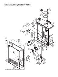
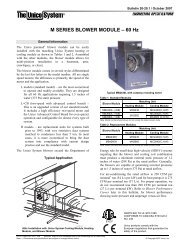
SL 80-399 MODULATING GAS BOILER1.01.1INSTALLATIONGENERALSL 80-399 gas-fired modula<strong>ting</strong> boilers are low pressure, fully condensingunits having a variable input range from 80 MBH to 399 MBH (0 to 8,000’). Theboilers are approved as “Category IV” vented appliances using either DirectVent (sealed combus<strong>tion</strong>) or indoor combus<strong>tion</strong> air, providing a great degree of<strong>inst</strong><strong>alla</strong><strong>tion</strong> flexibility.Figure 1 shows outer case dimensions <strong>and</strong> piping <strong>and</strong> electrical holes. Use thisdiagram to find a suitable loca<strong>tion</strong> for the boiler. See also Sec<strong>tion</strong> 1.3 Loca<strong>tion</strong>.DESCRIPTIONSIZEA Flue Outlet 4" O.D. CPVC/PVC PipeB Combus<strong>tion</strong> Air Inlet 4" O.D. PVC/ABS/CPVC PipeC Safety Relief Valve 3/4" NPTDLCD DisplayE Water Outlet 1 1/2” NPT - MF Water Inlet 1 1/2” NPT - MG Knock-outs (6) 1/2”H Gas Inlet 3/4” NPT - MI Condensate Outlet 3/4” Flexible Hose Barb Fit<strong>ting</strong>Table 1: Connec<strong>tion</strong>sFigure 1: Dimensions / Connec<strong>tion</strong>sINSTALLATION1-1
SL 80-399 MODULATING GAS BOILER1.2CODE REQUIREMENTSThe SL 80-399 boiler was tested to <strong>and</strong> certified under CSA 4.9-2010 / ANSIZ21.13-2010.Inst<strong>alla</strong><strong>tion</strong> must conform to local codes, or in the absence of these, with thelatest edi<strong>tion</strong>s of CAN/CGA B149 <strong>and</strong> the Canadian Electrical Code Part 1 CSAC22.2 No. 1.In the US, <strong>inst</strong><strong>alla</strong><strong>tion</strong>s must conform to the current Na<strong>tion</strong>al Fuel Gas CodeANSI Z223.1 <strong>and</strong> the Na<strong>tion</strong>al Electrical Code ANSI/NFPA 70. Where requiredby jurisdic<strong>tion</strong>, <strong>inst</strong><strong>alla</strong><strong>tion</strong> must conform to the St<strong>and</strong>ard for Controls <strong>and</strong> SafetyDevices for Automatically Fired Boilers, ANSI/ASME CSD-1. If there is anyconflict, then the more stringent requirement will apply.1-2WARNINGKeep boiler area free<strong>and</strong> clear of combustiblematerials, gasoline, <strong>and</strong>other flammable vapours<strong>and</strong> liquids.WARNINGCombus<strong>tion</strong> air must not bedrawn from areas containingcorrosive air from swimmingpools or spas, including airdirectly next to outdoor pools<strong>and</strong> spas.WARNING1.3The boiler shall not beexposed to water leaks frompiping or components locatedoverhead. This includescondensa<strong>tion</strong> dropping fromun-insulated cold water linesoverhead.LOCATIONThe SL series boilers are designed <strong>and</strong> approved for indoor <strong>inst</strong><strong>alla</strong><strong>tion</strong> (wall orrack moun<strong>ting</strong>), with significant flexibility of loca<strong>tion</strong> provided with the availableven<strong>ting</strong> op<strong>tion</strong>s. The boiler can be placed in an alcove, basement, closet or utilityroom. Surrounding ambient condi<strong>tion</strong>s shall be 0°C to 50°C <strong>and</strong> less than 90%relative humidity.Install the boiler in areas where the combus<strong>tion</strong> air source is not subject tochemical fouling or agricultural vapours. Exposure to corrosive chemicalfumes such as chlorinated <strong>and</strong>/or fluorinated hydrocarbons can reducethe life of a boiler. Cleaners, bleaches, air fresheners, refrigerants, aerosolpropellants, dry-cleaning fluids, de-greasers <strong>and</strong> paint-removers all containvapours which can form corrosive acid compounds when burned in a gas flame.Airborne chlorides such as those released with the use of laundry detergentsare also to be avoided. For this reason, the indoor air ven<strong>ting</strong> op<strong>tion</strong> using airsurrounding the boiler should not be used in a laundry room. Similarly, ensureany direct vent air source is not adjacent to a clothes dryer exhaust terminal.Avoid agricultural applica<strong>tion</strong>s where the boiler <strong>and</strong>/or the intake air sourceare affected by ammonia <strong>and</strong>/or dust.Locate the boiler where water leakage will not result in damage to the area. If aloca<strong>tion</strong> such as this cannot be found, a suitable drain pan should be <strong>inst</strong>alledunder the appliance. The boiler is not to be <strong>inst</strong>alled above carpe<strong>ting</strong>.Boiler weight – without water <strong>and</strong> any effect of system piping <strong>and</strong> components– is approx. 240 lbs/110 kg. For support fasteners, use the supplied 6 x 1/4” x 21/2" long lag screws. Installer to supply 1/4" bolts if metal moun<strong>ting</strong> systems areused. Fasteners are to be attached to solid material capable of suppor<strong>ting</strong> thecombined weight of the boiler <strong>and</strong> piping assembly components.Other factors affec<strong>ting</strong> potential moun<strong>ting</strong> sites:• Ensure minimum clearance requirements for combustible materials (seeTable 2) are satisfied.• Minimum 24" clearance at the front <strong>and</strong> 12” above is recommended foradequate servicing. Check local codes for addi<strong>tion</strong>al access <strong>and</strong> serviceclearance requirements.• At a new construc<strong>tion</strong> site, or during renova<strong>tion</strong>s, ac<strong>tion</strong> must be takento protect the boiler from drywall dust or other construc<strong>tion</strong> relatedINSTALLATION AND OPERATION INSTRUCTIONS
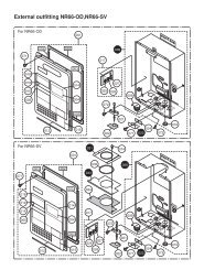
SL 80-399 MODULATING GAS BOILERcontaminants; combus<strong>tion</strong> air should be drawn from a CLEAN source(e.g. outdoors) <strong>and</strong> the boiler should be isolated from interior dustsources. Do not seal boiler case openings directly when firing - allow forair circula<strong>tion</strong> <strong>and</strong> ventila<strong>tion</strong> in the immediate area.SurfaceFront 1"Rear 0"Left Side 1"Right Side 1"Top 12”Bottom 12"Table 2 - Clearance from boiler cabinetDistance from Combustible SurfacesWARNINGDO NOT MOUNT THISBOILER TO HOLLOWWALL STRUCTURES - Thecombined weight of theboiler, its water contents<strong>and</strong> associated pipingcomponents can exceed 300pounds. Fasteners must berated for this strain, <strong>and</strong> mustbe firmly anchored into solidmaterial that will support thisweight.Installers are to take allnecessary precau<strong>tion</strong>sto avoid injury during the<strong>inst</strong><strong>alla</strong><strong>tion</strong> of this boiler.Figure 2: Wall moun<strong>ting</strong> of boilerA minimum distance below the boiler of 12" is required to provideclearance for the supplied condensa<strong>tion</strong> trap assembly. More clearance willtypically be required to accommodate associated water <strong>and</strong> gas piping.1.4EXHAUST Ven<strong>ting</strong> <strong>and</strong> AIR INTAKEDANGERDo not common vent SLseries modula<strong>ting</strong> boilerswith any other exis<strong>ting</strong> or newappliance.It is important to carefully plan the <strong>inst</strong><strong>alla</strong><strong>tion</strong> to ensure the appropriatevent materials, travel <strong>and</strong> termina<strong>tion</strong> decisions are incorporated. Specificatten<strong>tion</strong> is warranted to manage the impact of the steam plume normallyexperienced at the exhaust terminal of a condensing boiler. Generally,intake <strong>and</strong> exhaust pipes should terminate at a rooftop or sterile wallloca<strong>tion</strong>, to maximize customer satisfac<strong>tion</strong>. Keep exhaust plumeswell away from all building air intakes including those of neighbouringproperties.INSTALLATION1-3
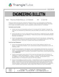
SL 80-399 MODULATING GAS BOILERDo not use ABS or any cellular core pipe for exhaust ven<strong>ting</strong>.The boiler offers 4" ven<strong>ting</strong> connec<strong>tion</strong>s. Fit<strong>ting</strong>s are to be used to adapt to theappropriate diameter – see Vent Travel below. Exhaust ven<strong>ting</strong> is to be inserteddirectly into the 4" female stainless steel fit<strong>ting</strong> on the top, left side of the boiler(see Figure 2).Combus<strong>tion</strong> air piping - if used - is inserted directly into the 4” female stainlesssteel fit<strong>ting</strong> on the top, right side of the boiler (see Sec<strong>tion</strong> 1.4.7).Ven<strong>ting</strong> shall be supported in accordance with applicable code.*Manufacturers of stainless steel Type BH ven<strong>ting</strong> systems must submittheir approved transi<strong>tion</strong> fit<strong>ting</strong> to IBC for evalua<strong>tion</strong> <strong>and</strong> written approval.1.4.3 Vent Travel4" CPVC or PVC ULC-S636 approved piping is the st<strong>and</strong>ard ven<strong>ting</strong> op<strong>tion</strong>; withthis, the SL 80-399 boiler can be sited up to 150 equivalent feet from the venttermina<strong>tion</strong>. The actual vent travel allowance is reduced for fit<strong>ting</strong>s in accordancewith Table 3. – e.g. for a SL 80-399 using 6 x 90º CPVC vent elbows, themaximum lineal measure of pipe allowed is 102 feet (150' – (6 x 8' = 48) = 102').EXHAUST Pipe Size4" 150' (each side)90° vent elbow allow 8’ equivalent90° long sweep elbow allow 5’ equivalent45° elbow allow 3' equivalentTable 3: Maximum exhaust ven<strong>ting</strong> lengthMaxIMUM EquivAlEnt LengthNote: Unused intake travel cannot be added to the exhaust. Unequalintake <strong>and</strong> exhaust piping is allowed - see Sec<strong>tion</strong> 1.4.8.Exhaust ven<strong>ting</strong> must slope down towards the boiler with a pitch of at least1/4" per foot so condensate runs back towards the trap. Support should beprovided for intake <strong>and</strong> vent piping, particularly so for horizontal runs (followlocal code). Insulate exhaust piping where it passes through unheated spaces orunderground, with appropriate pipe insula<strong>tion</strong> to prevent freezing of condensates.1.4.4 Ven<strong>ting</strong> Passage Through Ceiling <strong>and</strong> Floor• Confirm material meets local codes including fire stopping requirements.• Pipe clearances - no IBC requirements; follow local codes.• All piping must be liquid <strong>and</strong> pressure tight.Ensure all ven<strong>ting</strong> components are clean of burrs/debris prior to assembly.Care is to be taken to avoid inges<strong>tion</strong> into the fan of plastic debris left in thecombus<strong>tion</strong> air piping.All joints must be secured using appropriate solvent cement to bond therespective pipe material (Canada: PVC, CPVC or transi<strong>tion</strong> cement approvedunder ULC-S636, in accordance with its manufacturer <strong>inst</strong>ruc<strong>tion</strong>s; USA: PVC(ASTM D2564), or PVC/ABS (D2235) Use transi<strong>tion</strong> glue anywhere that PVC <strong>and</strong>CPVC are joined. Follow the cement manufacturer’s <strong>inst</strong>ruc<strong>tion</strong>s closely whenjoining various components.1-6INSTALLATION AND OPERATION INSTRUCTIONS
SL 80-399 MODULATING GAS BOILERAll vent connec<strong>tion</strong>s must be liquid <strong>and</strong> pressure tight. Prior to firing the boiler,<strong>and</strong> before any of the ven<strong>ting</strong> run is concealed by the building construc<strong>tion</strong>, the<strong>inst</strong>aller must test the exhaust joints under fan pressure with the vent blocked,using a soap/water solu<strong>tion</strong>. Installer must fill condensate trap prior to test.Remove the fan control harness plug as illustrated in the photos, <strong>and</strong> then blockthe vent outlet so that the vent run will be under maximum fan pressure. Paint alljoints with an approved leak test solu<strong>tion</strong> just as you would joints in a gas line,<strong>and</strong> make sure there are no leaks. Good practice would suggest that the <strong>inst</strong>allerattach a tag on the vent line near the condensate drain tee indica<strong>ting</strong> the type oftest, the date <strong>and</strong> the <strong>inst</strong>aller’s name.1.4.5 Rooftop Vent Termina<strong>tion</strong>Fan control harness plugUnplugging fan control harness plugwill drive the fan into manual highspeed <strong>opera</strong><strong>tion</strong> for vent leak testRooftop vents must terminate as follows:• The exhaust pipe can terminate in an open vertical orienta<strong>tion</strong> without concernabout rain infiltra<strong>tion</strong>; rain will drain away through the condensate trap.• If used, the intake air pipe is not typically drained, so it must be terminatedwith a down-turned elbow (see Figure 4). The intake pipe does not need topenetrate the roof at the same eleva<strong>tion</strong> as the exhaust (as shown); lowerdown roof is OK.• Op<strong>tion</strong>al bird screen may be placed in a termina<strong>tion</strong> fit<strong>ting</strong>. Leave unglued,<strong>and</strong> hold in place with a short nipple. This permits easy access for cleaning.• For roof top ven<strong>ting</strong> of multiple boiler sets, group all intake terminals togetherfor a common penetra<strong>tion</strong> through a custom cap. Alternatively, place in theclosest proximity achievable using commonly available pipe flashing. Similarlygroup the exhaust pipes <strong>and</strong> place the 2 separate groups of pipes at least 3'apart (the closest intake <strong>and</strong> exhaust pipes shall be 36" - or more - apart).Use the same 24" (minimum) vertical separa<strong>tion</strong> for all termina<strong>tion</strong> op<strong>tion</strong>s.• DO NOT exhaust vent into a common ven<strong>ting</strong> system.WARNINGCondensate can causecorrosion of metal roofingcomponents <strong>and</strong> otherroofing materials. Checkwith the builder or roofingcontractor to ensure thatmaterials will be resistant toacidic condensate. pH levelscan be as low as 3.0Figure 4: Rooftop vent terminal configura<strong>tion</strong>sINSTALLATION1-7
SL 80-399 MODULATING GAS BOILERSidewall indoor combus<strong>tion</strong> air applica<strong>tion</strong>s shall be vented as follows:• The exhaust outlet is to be placed 18” minimum (12” in USA) above the gradeor anticipated snow level.• The vent shall be terminated with a tee fit<strong>ting</strong> as illustrated - See Figure 6.• Bird screen, as above, should be <strong>inst</strong>alled in both open ends of the tee.For side ven<strong>ting</strong> of multiple boiler sets, group all intake terminals together with 6"to 12" lateral spacing, <strong>and</strong> similarly group the exhaust pipes. Place the 2 groupson the same plane of the building (e.g. north facing wall). Place the 2 groups ofpipes at least 3' apart (the closest intake <strong>and</strong> exhaust pipes shall be 36" - or more– apart. Use same 24" (minimum) vertical separa<strong>tion</strong>.Figure 9: Sidewall vent termina<strong>tion</strong> - multiple vent piping configura<strong>tion</strong>Vent terminal clearance minimums are as follows:Figure 7: IBC recommendedminimum vent terminal clearanceunder ventilated soffitFigure 8: Prohibited <strong>inst</strong><strong>alla</strong><strong>tion</strong>INSTALLATION• Clearance above grade, ver<strong>and</strong>a, porch, deck or balcony – 12" (0.3m), butcheck local code also (anticipated snow levels may supersede).• Clearance to openable window or door – 36" (0.91m) (USA – 12”)• Vertical clearance to ventilated soffit located above the terminal - 48” (1.2m)See Cau<strong>tion</strong> note in this sec<strong>tion</strong>.• Clearance to each side of centre line extended above meter/regulatorassembly: - 3' (0.91m) within a height of 15' (4.6m) above the meter/regulator.• Clearance to service regulator vent outlet: - 3' (0.91m)• Clearance to non-mechanical air supply inlet to building or the combus<strong>tion</strong> airintake to any other appliance: - 3' (0.91m) (USA – 12" (0.3m))• Clearance to a mechanical air supply inlet: - 6’ (1.82m) (USA - 3’ (0.91m)above if within 10’ (3.1m) horizontally)• Clearance above paved sidewalk or paved driveway located on publicproperty: - 7' (2.2m) Note: Cannot terminate directly above a paved sidewalkor paved driveway that is located between two single family dwellings <strong>and</strong>serves both dwellings• Clearance under ver<strong>and</strong>a, porch, deck or balcony: - 12" (0.3m) IBC stronglyrecommends a minimum of 48” with the SL 80-399 to avoid damage tothe structure. Note: Prohibited unless fully open on a minimum of two sidesbelow the floor.1-9
SL 80-399 MODULATING GAS BOILERWARNINGIn areas of high snowfall,Users must be advised tocheck side wall vent <strong>and</strong>air intake termina<strong>tion</strong>s ona regular basis to ensureblockage does not occur.• Vents must be <strong>inst</strong>alled such that flue gas does not discharge towardsneighbor’s windows, or where personal injury or property damage can occur.• It is important to ensure proper condensate management from venttermina<strong>tion</strong>s. Condensate shall not be discharged in a manner that will causedamage to external building finishes or components, or infiltrate buildingenvelopes, including adjacent structures.CAUTIONVent termina<strong>tion</strong> clearancesin this sec<strong>tion</strong> arecode minimum, or IBCrecommended minimumrequirements, <strong>and</strong> maybe inadequate for your<strong>inst</strong><strong>alla</strong><strong>tion</strong>. Building envelopedetails must be examinedcarefully, <strong>and</strong> ingress ofmoisture into buildingstructures is to be avoided.Serious structural damagemay occur if adequateprecau<strong>tion</strong>s <strong>and</strong> clearancesare not allowed for.These precau<strong>tion</strong>s are to beobserved for neighbouringstructures as well as for thestructure the boiler(s) are<strong>inst</strong>alled in.Figure 10: Vent terminal clearancesFigure 11: Vent terminal clearances1-10INSTALLATION AND OPERATION INSTRUCTIONS
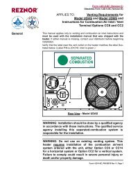
SL 80-399 MODULATING GAS BOILERWARNINGIn addi<strong>tion</strong> to preven<strong>ting</strong>inges<strong>tion</strong> of chemicalcontaminants, care mustbe taken to ensure airintake terminals are not<strong>inst</strong>alled in loca<strong>tion</strong>s wherecontamina<strong>tion</strong> might occurdue to inges<strong>tion</strong> of particulateforeign material (dust, dirt<strong>and</strong> debris).1.4.7 “Direct Vent” Combus<strong>tion</strong> Air Intake PipingThere are two basic methods of supplying combus<strong>tion</strong> air to an IBC boiler.The direct vent op<strong>tion</strong> uses piping from the outside to supply combus<strong>tion</strong> airdirectly to the boiler’s combus<strong>tion</strong> air connec<strong>tion</strong>.WARNINGIntake air openings must beconfigured such that rainor other forms of moisturecannot enter the air intakepiping system. Otherwiseserious damage to the boilermay result.Figure 12: Direct vent combus<strong>tion</strong> air intakeNOTECare must be taken when<strong>inst</strong>alling air intake piping toensure that a “trap” is notformed in the piping so as toallow a build-up of water, <strong>and</strong>blockage of intake air.Such blockage will result in aboiler safety shut-down.INTAKE Pipe SizeMaxIMUM EquivAlEnt Length4" 150' (each side)90° vent elbow allow 8' equivalent90° long sweep elbow allow 5’ equivalent45° elbow allow 3’ equivalentAir Intake FilterContact FactoryTable 4: Maximum intake piping lengthFor the inlet air – 4” Schedule 40 PVC, CPVC or ABS piping of any type ispermitted.Note: It is not permitted to add to the exhaust length by transfer of unusedintake allowance.Combus<strong>tion</strong> air piping - if used - is inserted directly into the 4” female stainlesssteel fit<strong>ting</strong> on the top, right side of the boiler <strong>and</strong> run horizontally or vertically tothe outdoors. Screen material can be placed at the inlet as appropriate for theenvironment (e.g. insects, dust).Care must be taken to ensure adequate separa<strong>tion</strong> is maintained between theair intake inlet <strong>and</strong> the vent terminal. Refer to the vent terminal configura<strong>tion</strong>drawings in the Vent Termina<strong>tion</strong> sec<strong>tion</strong> above.Support should be provided for intake piping, particularly so for horizontal runs(follow local code).INSTALLATION1-11
SL 80-399 MODULATING GAS BOILER1.4.8 “Indoor Air” Combus<strong>tion</strong> Air IntakeWARNINGWhen using IndoorAir op<strong>tion</strong>s, adequatecombus<strong>tion</strong> air must besupplied to the boiler roomaccording to the requirementsof all applicable codes.An “Indoor Combus<strong>tion</strong> Air <strong>inst</strong><strong>alla</strong><strong>tion</strong>”, as described herein, is one in which airfor combus<strong>tion</strong> is taken from the ambient air around the boiler.Figure 15: Indoor combus<strong>tion</strong> air intakeTo support combus<strong>tion</strong>, an ample air supply is required. This may requiredirect openings in the boiler room to the outside. If the boiler is not in a roomadjacent to an outside wall, air may be ducted from outside wall openings.Figure 13: ReservedProvisions for combus<strong>tion</strong> <strong>and</strong> ventila<strong>tion</strong> air must be made as follows:• in the USA, in accordance with Sec<strong>tion</strong> 5.3 Air for Combus<strong>tion</strong> <strong>and</strong>Ventila<strong>tion</strong> of the Na<strong>tion</strong>al Fuel Gas Code, ANSI Z223.1 (latest edi<strong>tion</strong>), orapplicable provisions of the local building codes• in Canada, in compliance with B149.1.4.9 Combus<strong>tion</strong> Air Filtra<strong>tion</strong>If combus<strong>tion</strong> air contamina<strong>tion</strong> from ingested particulate matter may be aconcern in any <strong>inst</strong><strong>alla</strong><strong>tion</strong>, an op<strong>tion</strong>al air intake filter may be <strong>inst</strong>alled.Important Note: At the time of this prin<strong>ting</strong>, a combus<strong>tion</strong> air filter for theSL 80-399 model was not yet available. Contact the Factory if your applica<strong>tion</strong>requires air filtra<strong>tion</strong>. Under no circumstances should a third-party air filter be<strong>inst</strong>alled on an IBC boiler without proper evalua<strong>tion</strong> <strong>and</strong> written approval of theIBC Engineering Department.1.4.10 Closet Inst<strong>alla</strong><strong>tion</strong>sFigure 14: ReservedFor <strong>inst</strong><strong>alla</strong><strong>tion</strong>s in a confined space (such as a closet), ventila<strong>tion</strong> openings maybe needed through a door or wall to prevent excessive heat from building upinside the space.The boiler shall not be exposed to ambient condi<strong>tion</strong>s above 122°F (50°C) orbelow 32°F (0°C).1-12INSTALLATION AND OPERATION INSTRUCTIONS
SL 80-399 MODULATING GAS BOILERNOTE1.5Combus<strong>tion</strong> fanblockages can occur whenenvironmental particulate <strong>and</strong>foreign matter contaminants(leaves, dust, d<strong>and</strong>elion &cottonwood fluff, etc) aredrawn into the air intake. Inareas where this problem issuspected to be an issue,intake air filtra<strong>tion</strong> should beconsidered. Contact Factory.Filters should be checked<strong>and</strong> cleaned or replaced ona regular schedule based onthe severity of the problem.CONDENSATE REMOVALIBC’s specified vent configura<strong>tion</strong> promotes the safe drainage of moisturefrom the boiler <strong>and</strong> exhaust ven<strong>ting</strong> without flowing liquids back through theheat exchanger (as done by some other condensing boilers). Reliable system<strong>opera</strong><strong>tion</strong> requires (1) proper design <strong>and</strong> <strong>inst</strong><strong>alla</strong><strong>tion</strong> of exhaust ven<strong>ting</strong> toallow condensate to run back to the drain/trap; (2) acid neutraliza<strong>tion</strong> asappropriate. To achieve these:1. Allow for a 1/4” per foot slope back to the vent connec<strong>tion</strong>, withappropriate hangers to maintain that gradient.2. Ensure the supplied trap is correctly <strong>inst</strong>alled <strong>and</strong> filled with water.3. When required, add (<strong>and</strong> maintain in good condi<strong>tion</strong>) a neutraliza<strong>tion</strong>tank.1.5.1 Condensate TrapA condensate trap must be <strong>inst</strong>alled on the drain connec<strong>tion</strong> at the base ofthe boiler as shown in Figure 16.WARNINGWhen using IndoorAir op<strong>tion</strong>s, adequatecombus<strong>tion</strong> air must besupplied to the boiler roomaccording to the requirementsof all applicable codes.Figure 16: Condensate trap <strong>inst</strong><strong>alla</strong><strong>tion</strong>INSTALLATION1-13
SL 80-399 MODULATING GAS BOILERWARNINGFill trap with water beforeboiler is first fired to preventexhaust fumes from enteringroom. Never <strong>opera</strong>te theboiler unless the trap is filledwith water.Failure to comply will resultin severe personal injury ordeath.1.5.2 Condensate Trap Assembly Inst<strong>alla</strong><strong>tion</strong>1. Undo Drain Spout Compression Nut (D),remove Drain Spout (C) fromCondensate Drain Outlet (E) of Trap Body (A).2. Loosen Upper Compression Nut (B) <strong>and</strong> place the Nut <strong>and</strong> Trap Body (A) overBoiler Condensate Outlet (G) far enough to swing Trap Hook (F) down <strong>and</strong>past the Drain Spout connec<strong>tion</strong> threads. Pull the trap slightly downward toseat it aga<strong>inst</strong> the hook.3. Unscrew Trap Body from trap top piece, <strong>and</strong> fill with water. Screw Trap Bodyback to top piece.4. H<strong>and</strong> Tighten Upper Compression Nut <strong>and</strong> secure Drain Hose to Drain Spoutbarb connec<strong>tion</strong>. If the nut is removed, ensure the cone seal <strong>and</strong> backupo-ring remain in the factory supplied posi<strong>tion</strong>. Gently pull on all assembledcomponents to make sure they are secured in posi<strong>tion</strong>.Factory supplied condensate trapwith drain hose1.5.3 Condensate Trap cleaning procedure1. Turn off the power to the boiler <strong>and</strong> allow it to cool down.2. Unscrew trap body (A) from trap top piece.3. Unscrew trap bottom piece from main trap body <strong>and</strong> clean <strong>and</strong> flush debrisfrom these components. In cases of severe fouling, Drain Spout may haveto be removed, <strong>and</strong> trap top piece removed from boiler condensate outlet forfurther cleaning of those components.4. Re-assemble trap components, re-fill trap, <strong>and</strong> replace on boiler as describedin the Condensate Trap Assembly Inst<strong>alla</strong><strong>tion</strong> <strong>inst</strong>ruc<strong>tion</strong>s above.1.5.4 Further <strong>inst</strong><strong>alla</strong><strong>tion</strong> detailsFigure 17: Condensate trapdisassembly for cleaning1-14• Condensate drain must be piped to within 1” of a drain or be connected to acondensate pump.• Drainage line must slope down to the drain at a pitch of 1/4” per foot socondensate runs towards the drain.• Condensate traps should be checked every 2 months, <strong>and</strong> cleaned <strong>and</strong>refilled as necessary.INSTALLATION AND OPERATION INSTRUCTIONS
SL 80-399 MODULATING GAS BOILERWARNINGIf condensates are to bedischarged into buildingdrain piping materials thatare subject to corrosion, aneutraliza<strong>tion</strong> package mustbe used.CONDENSATE DRAINAGEFree flow of condensate from ven<strong>ting</strong>system <strong>and</strong> pressure vessel must bemaintained at all times. Trap <strong>and</strong>condensate drain piping must beaccessible to allow regular inspec<strong>tion</strong><strong>and</strong> cleaning.WARNING: “Risk of damage to appliance”All condensate discharge lines must be ata lower eleva<strong>tion</strong> than the condensatewater line of the appliance.FLUE GAS EXHAUSTCONDENSATE AND RAINWATER FLOWS BACK FROMVENTING SYSTEMIBCSL 80-399BOILERCONDENSATE WATER LINEIBCFACTORY SUPPLIEDCONDENSATE TRAPATTACH HOSETO DRAINAGE PIPINGCONDENSATE HOSE AND DRAINPIPING TO SLOPE TOWARDDRAIN AND BE SECURED TOPREVENT ACCIDENTAL DISASSEMBLY.TODRAINFigure 18: Condensate trap drainageDRAIN MATERIALS SUBJECT TOCORROSION MUST BE PROTECTEDBY ACID NEUTRALIZATIONCAUTIONWhen a condensateneutraliza<strong>tion</strong> packageis <strong>inst</strong>alled, the pH of thecondensate discharge mustbe measured on a regularschedule to ensure theneutralizing agent is active<strong>and</strong> effective.MAINTENANCE DETAILS FORNT20 CONDENSATENEUTRALIZATION TANKRefer to manufacturer’s maintenance<strong>inst</strong>ruc<strong>tion</strong>s for other makes <strong>and</strong> modelsof condensate neutraliza<strong>tion</strong> tanksWARNING: “Risk of damage to appliance” Neutraliza<strong>tion</strong>tank inlet <strong>and</strong> discharge must be at a lower eleva<strong>tion</strong> thanthe condensate water line of the appliance.FLUE GAS EXHAUSTCONDENSATE AND RAINWATER FLOWS BACK FROMVENTING SYSTEMIBCSL 80-399BOILERNOTE: Access to the discharge before the drain isnecessary for proper maintenance in order to check theeffectiveness of the neutralizing agent. A simple pH testshould be performed annually to ensure neutralizing agentis still effective. If pH falls below 6.5 the neutralizing materialshould be replaced. The agent (limestone chips with aminimum calcium carbonate content of 85%) can bepurchased from a local supplierIBC1 1/2” FIPOUTLET1 1/2” FIPINLETTO DRAINFigure 19: Condensate neutraliza<strong>tion</strong> tankINSTALLATION1-15
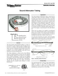
SL 80-399 MODULATING GAS BOILER1.6Water PipingWARNINGDuring <strong>opera</strong><strong>tion</strong>, the reliefvalve may discharge largeamounts of steam <strong>and</strong>/or hotwater. Therefore, to reducethe potential for bodilyinjury <strong>and</strong> property damage,a discharge line MUST be<strong>inst</strong>alled that it:1.6.1 General Piping IssuesThe SL modula<strong>ting</strong> series boilers are designed for use within a closed loop,forced circula<strong>tion</strong>, low pressure system. A 30 psi pressure relief valve (3/4" NPT)is supplied for field <strong>inst</strong><strong>alla</strong><strong>tion</strong> in the relief valve fit<strong>ting</strong> on top of the boiler. Reliefvalve discharge piping must terminate between 6" (15cm) <strong>and</strong> 12” (30cm) abovethe floor or per local Code.1. is connected from the valve outletwith no intervening valve <strong>and</strong>directed downward to a safe point ofdischarge.2. allows complete drainage of both thevalve <strong>and</strong> the discharge line.3. is independently supported <strong>and</strong>securely anchored so as to avoidapplied stress on the valve.4. is as short <strong>and</strong> straight as possible5. terminates freely to atmospherewhere any discharge will be clearlyvisible <strong>and</strong> is at no risk of freezing.6. terminates with a plain end which isnot threaded.7. is constructed of a material suitablefor exposure to temperatures of375°F or greater.8. is, over its entire length, of a pipe sizeequal to or greater than that of thevalve outlet.DO NOT CAP, PLUG OR OTHERWISEOBSTRUCT THE DISCHARGE PIPEOUTLET!NOTEInstallers should inquire oflocal water purveyors as tothe suitability of their supplyfor use in hydronic hea<strong>ting</strong>systems.If water quality is ques<strong>tion</strong>able,a local water treatment expertmust be consulted for tes<strong>ting</strong>,assessment <strong>and</strong>, if required,treatment.Alternatively, water or hydronicfluid of known quality can bebrought to the site.Figure 20: Boiler trim op<strong>tion</strong>s - Single boilerSystem piping is connected to the boiler using the 1 1/2" NPT-M threaded fit<strong>ting</strong>s.Unions <strong>and</strong> gate or ball valves at the boilers supply <strong>and</strong> return water connec<strong>tion</strong>sare recommended to simplify servicing. Un-insulated hot water pipes must be<strong>inst</strong>alled with a minimum 1" clearance from combustible materials.Fluid fill is most often accomplished by using a boiler regulator & fill valve setat 12 psig or more, with appropriate backflow preven<strong>tion</strong> device as requiredby local code. This is acceptable in areas where municipal water or well waterhas been treated <strong>and</strong> filtered to remove excessive minerals <strong>and</strong> sediment, <strong>and</strong>water chemistry is known to be suitable for closed loop hydronic systems. Inareas where water quality is in ques<strong>tion</strong>, or when chemical treatment or glycol isrequired, other op<strong>tion</strong>s should be considered. Follow applicable Codes <strong>and</strong> goodpiping practice.There are a number of boiler feed <strong>and</strong> pressuriza<strong>tion</strong> devices on the markettoday that may be a better choice than a raw water fill from the mains. Whenregular maintenance requires relief valve blow-off, the discharge may be directedback into the pressuriza<strong>tion</strong> unit for recycling of boiler fluid <strong>and</strong> chemicalsback into the system. In buildings that may be unoccupied for long periods oftime, pressuriza<strong>tion</strong> units are useful to prevent flood damage should leakageoccur from any component in the system. An addi<strong>tion</strong>al benefit is that backflowpreven<strong>tion</strong> devices are not required when using these devices.1-16INSTALLATION AND OPERATION INSTRUCTIONS
SL 80-399 MODULATING GAS BOILERWARNINGClose fill valve after anyaddi<strong>tion</strong> of water to thesystem, to reduce risk ofwater escapement.Do not place any water connec<strong>tion</strong>s overhead the boiler; leaks can damagethe fan & controls. If needed, create a shield over the top of the cover, but allowclearance for airflow <strong>and</strong> service access.For best results, use a Primary: Secondary piping system, with a pumped boilerloop using 2" piping for the SL 80-399. Heat exchanger head is only 2’ at 30 gpm<strong>and</strong> approx. 4' at 40 gpm.The minimum flow rate required through the heat exchanger is 20 gpm <strong>and</strong> amaximum of 45 gpm is allowed. Primary/Secondary piping ensures adequateflow <strong>and</strong> de-couples Δ°T issues (boiler vs. distribu<strong>tion</strong>). Aim for a 20° to 30° F Δ°Tacross the heat exchanger at high fire (there is a boiler protec<strong>tion</strong> throttle fencelimi<strong>ting</strong> the Δ°T to 35°F).Table 5: ReservedFigure 21: Primary/Secondary piping concept with hydraulic separatorThe SL modula<strong>ting</strong> series boilers can supply multiple hea<strong>ting</strong> loads withcompatible supply temperature requirements. Always ensure that loads sensitiveto high temperatures are protected using means such as a mixing valves.A variety of applica<strong>tion</strong> drawings showing basic design op<strong>tion</strong>s are available fromthe IBC web site at: www.ibcboiler.comNOTEFull sized applica<strong>tion</strong>drawings can be downloadedfrom our web site.www.ibcboiler.comPRESSURE VESSEL HEADFlow rate (gpm) 20 35 30 35 40 45Head @ flow (ft wc) 1 1.5 2 3 4 6Table 6: Pressure Vessel HeadWe require water flow after burner shutdown to utilize legacy heat – this issignificant due to the mass of the heat exchanger (50 Kg) plus its 26L internalwater volume. Default software values will run the boiler’s primary pump for upto 5 minutes (300 seconds) after burner shutdown. Secondary pumps can beset to run up to 5 minutes after burner shutdown (for the last calling load). Asshipped, the default software will run the Load 1 pump for 5 minutes to place theINSTALLATION1-17
SL 80-399 MODULATING GAS BOILERlegacy heat where it is useful. Any secondary pump can be set to run for 0 – 300seconds in the heat purge mode. Guard aga<strong>inst</strong> deadheading pumps when allzone valves are closed (see Sec<strong>tion</strong> 2.7 Set Up & Load Defini<strong>tion</strong>).The primary pump must be under the control of the boiler, to allow the boiler’sflow proving routine to run. The boiler control looks for flow/no flow during apump on / off check on each start up. Ensure that temporarily wired primary orsecondary pumps (e.g. wired externally during the system fill/purge phase) arereturned to the boiler’s control terminals. A “No Water Flow” error message willotherwise be experienced on start-up.Schematics for several piping layouts are provided, <strong>and</strong> addi<strong>tion</strong>al drawings areavailable at www.ibcboiler.com. Installers shall conform the piping design to oneof the provided configura<strong>tion</strong>s to simplify the control applica<strong>tion</strong>, promote goodloads <strong>and</strong> flow management.WARNINGDo not use automotive-typeethylene or other types ofautomotive glycol antifreeze,or undiluted antifreeze ofany kind. This may resultin severe boiler damage. Itis the responsibility of theInstaller to ensure that glycolsolu<strong>tion</strong>s are formulated toinhibit corrosion in hydronichea<strong>ting</strong> systems of mixedmaterials. Improper mixtures<strong>and</strong> chemical additives maycause damage to ferrous <strong>and</strong>non-ferrous components aswell as non-metallic, wettedcomponents, normally foundin hydronic systems. Ethyleneglycol is toxic, <strong>and</strong> may beprohibited for use by codesapplicable to your <strong>inst</strong><strong>alla</strong><strong>tion</strong>loca<strong>tion</strong>. For environmental<strong>and</strong> toxicity reasons, IBCrecommends only using nontoxicpropylene glycol.Propylene glycol solu<strong>tion</strong> is commonly used in a closed loop where freezeprotec<strong>tion</strong> is required. Its density is lower than that of water, resul<strong>ting</strong> inlower thermal performance at a given flow <strong>and</strong> pressure. As a rule of thumb,a 50%:50% solu<strong>tion</strong> of propylene glycol <strong>and</strong> water will require an increasedsystem circula<strong>tion</strong> rate (gpm up 10%), <strong>and</strong> system head (up 20%) to provideperformance equivalent to straight water.1.6.2 Inst<strong>alla</strong><strong>tion</strong> RulesThe boiler control hardware used is common to the smaller VFC 15-150 <strong>and</strong>45-225 models; these smaller models feature IBC’s hallmark 3-load loadmanagement system. However, as it would normally be inappropriate to applythat sequential load run strategy on larger commercial-scale loads, the 80-399software has been changed – specifically covering temperature transi<strong>tion</strong> duringload switching – to discourage diverse multiple load applica<strong>tion</strong>s. Where Factoryapproval is granted, tradi<strong>tion</strong>al 3-load code will be made available.Figure 22: Primary/Secondary piping concept with simultaneous setpoint calls1-18INSTALLATION AND OPERATION INSTRUCTIONS
SL 80-399 MODULATING GAS BOILERNOTEThe Primary (boiler) pumpmust be under the controlof the boiler <strong>and</strong> wired tothe correct yellow <strong>and</strong> whitewires labelled “Primary” inthe wiring box.Failure to do so will resultin a no heat condi<strong>tion</strong> as theboiler will interrupt start-upwith a “No Water Flow” error.If the <strong>inst</strong><strong>alla</strong><strong>tion</strong> involves small loads, as in typical zoned baseboard hea<strong>ting</strong>applica<strong>tion</strong>s, use of a buffer tank is recommended. To aid in temperaturetransi<strong>tion</strong> from hot to cool loads, a 3-way mixing valve can be placed at theentrance to the cool load (this will also provide floor protec<strong>tion</strong>). This will permitimmediate circula<strong>tion</strong> of mixed flow into the cool loop. See separate publica<strong>tion</strong>Applica<strong>tion</strong> Notes for more detail (available at www.ibcboiler.com or from yourIBC Representative).Always ensure that loads sensitive to high temperatures (e.g. radiant floor)are protected using appropriate means such as a manual mixing valve, or anaquastat (set to130°F, for example) wired to the boiler’s auxiliary interlocks.Figure 23: Two pump, two load - parallel piping conceptCompared with the Primary/Secondary approach, the above design saves onepump. Lost is the simplicity of constant head <strong>and</strong> flow at the boiler.Wiring: In these parallel pumping applica<strong>tion</strong>s, disconnect the wire from thePump Block, terminal 11 (P/V Power - L), <strong>and</strong> isolate it using a wire nut, crimpconnector or other secure means to prevent the bare wire from contac<strong>ting</strong>anything. Install a wire into the Power Block, terminal 1 (BP - L), <strong>and</strong> jumper upto Pump Block, terminal 11 (P/V Power - L). This procedure will allow the boilerto <strong>opera</strong>te the load pumps through the Boiler Pump contacts, in order to provideflow proving <strong>opera</strong><strong>tion</strong>.Check valves or thermal traps should be used to isolate both the supply <strong>and</strong>return piping for each load - to avoid thermal siphoning <strong>and</strong> reverse flow.To ensure adequate water flow through the boiler under high-head / singlezone space hea<strong>ting</strong> condi<strong>tion</strong>s, a pressure activated bypass or other means ofbypass must be used on any load where the flow rate might drop below minimumrequirements (20 gpm).For further informa<strong>tion</strong> <strong>and</strong> details, consult our Applica<strong>tion</strong> Notes – which providedetail on specific single <strong>and</strong> multiple boiler applica<strong>tion</strong>s “Piping”, “Wiring” <strong>and</strong>“Set<strong>ting</strong>s”. (available at www.ibcboiler.com or from your IBC Representative).INSTALLATION1-19
SL 80-399 MODULATING GAS BOILERNOTEThis piping drawings in thismanual are simple schematicguides to a successful<strong>inst</strong><strong>alla</strong><strong>tion</strong>. There are manynecessary components notshown, <strong>and</strong> details such asthermal traps are left out sothe drawings have greaterclarity. We require thatour boilers be <strong>inst</strong>alled bylicensed <strong>and</strong> experiencedtrades people who are familiarwith the applicable local<strong>and</strong> na<strong>tion</strong>al codes. Systemdesign is to be completedby an experienced hydronicdesigner or Engineer. It isnecessary to carefully read<strong>and</strong> follow these <strong>inst</strong><strong>alla</strong><strong>tion</strong><strong>inst</strong>ruc<strong>tion</strong>s along with theapplica<strong>tion</strong> drawing that fitsyour system.Figure 24: Trim for multiple boiler <strong>inst</strong><strong>alla</strong><strong>tion</strong>sFigure 25: Multi boiler rack moun<strong>ting</strong>Figure 26: Front view rack moun<strong>ting</strong>1-20INSTALLATION AND OPERATION INSTRUCTIONS
SL 80-399 MODULATING GAS BOILERNOTEWhen using the sequentialload feature of the IBC boiler,atten<strong>tion</strong> must be paid tothe <strong>opera</strong><strong>tion</strong> of systemcomponents in order toensure they are compatible.Many air h<strong>and</strong>lers (fancoils) for <strong>inst</strong>ance have athermostat connec<strong>tion</strong> thatwill energize an internal relayto <strong>opera</strong>te the air h<strong>and</strong>lercirculator <strong>and</strong> its fan ona call for heat. This mayresult in <strong>opera</strong><strong>tion</strong> of thesecomponents when otherloads are running at a higherpriority, resul<strong>ting</strong> in cold airblowing, or robbing heat fromanother load.Some wiring altera<strong>tion</strong> maybe required to divorce bothof these func<strong>tion</strong>s fromthermostat control in favourof more effective control fromthe IBC boiler.Figure 27: Multiple boiler pipingFigure 28: Multiple boiler inter-wiringINSTALLATION1-21
SL 80-399 MODULATING GAS BOILER1.7Gas PipingThe boiler requires an inlet gas pressure of at least 5.0" w.c. for natural gas orpropane. For either fuel, the inlet pressure shall be no greater than 14.0" w.c.Confirm this pressure range is available with your local gas supplier.The inlet gas connec<strong>tion</strong> of the boiler’s gas valve is 3/4" NPT (male).Adequate gas supply piping shall be provided with no smaller than 3/4" Sched 40(e.g. Iron Pipe Size (IPS)) <strong>and</strong> using a 1" w.c. pressure drop, in accordance withthe following chart:Model 3/4" IPS 1" IPS 1 1/4" IPS 1 1/2" IPSSL 80-399 (Natural Gas) 10 40 150 350SL 80-399 (Propane) 30 100 400 900Table 7: Maximum Pipe Length (ft)Gas piping must have a sediment trap ahead of the boiler’s gas valve (see Figure29). A manual shutoff valve must be located outside the boiler, in accordance withlocal codes/st<strong>and</strong>ards. All threaded joints in gas piping should be made with anapproved piping compound resistant to the ac<strong>tion</strong> of natural gas/propane. Useproper hangers to support gas supply piping as per applicable codes.The boiler must be disconnected or otherwise isolated from the gas supplyduring any pressure tes<strong>ting</strong> of the system at test pressures in excess of 1/2 psig.Dissipate test pressure prior to reconnec<strong>ting</strong>. The boiler <strong>and</strong> its gas piping shallbe leak tested before being placed into <strong>opera</strong><strong>tion</strong>.The gas valve is provided with pressure taps to measure gas pressure upstream(supply pressure) <strong>and</strong> downstream (manifold pressure) of the gas valve (seeFigure 32). Note that manifold pressure varies slightly in accordance with firingrates with the modula<strong>ting</strong> series boilers, but will always be close to 0” w.c.Figure 29: Typical gas piping1-22INSTALLATION AND OPERATION INSTRUCTIONS
SL 80-399 MODULATING GAS BOILER1.8Electrical Connec<strong>tion</strong>sAll Electrical wiring to the boiler (including grounding) must conform to localelectrical codes <strong>and</strong>/or Na<strong>tion</strong>al Electrical Code, ANS/NFPA No. 70 – latestedi<strong>tion</strong>, or The Canadian Electrical Code, C22.1 - Part 1.1.8.1 115Vac Line Voltage Hook-upRemoving wiring box coverLine-voltage wiring is done within the field-wiring box. (Refer to Sec<strong>tion</strong>6.2.Wiring Diagram on page 6-4). Connect the boiler to the grid power using aseparate, fused circuit <strong>and</strong> on/off switch within sight of the boiler. Use 14-gaugewire in BX cable or conduit properly anchored to the boiler case for mains supply<strong>and</strong> pump circuits.Connect a 115 VAC / 15 amp supply to the power block terminal strip (terminals 3<strong>and</strong> 4) in the wiring box. The max. actual draw shall not exceed 12 amps.If primary / secondary piping is used, with pumps to manage multiple loads,connect them to the pump terminal block located above the power block. Theupper 3 pairs of contacts on this block are powered to manage up to 3 loadpumps – the top pair for Load 1, the second pair for #2 etc. Once the controlleris programmed for the respective loads, the boiler will manage all the loadswithout need of further relays (maximum pump electrical draw up to 1/3 HP. Useprotective relays for higher draws).Line voltage power block terminalsLine voltage pump block terminalsCAUTIONThe internal pump relays in theIBC control have a maximumra<strong>ting</strong> of 5 Amps or 1/3 H.P.each, with a maximum totalallowable draw of 10 amps.Isola<strong>tion</strong> contactors MUST beused if electrical loads exceedthese maximums.The boiler pump is connected to the power block (terminals 1 <strong>and</strong> 2). Theseterminals are factory wired to the controller (<strong>and</strong> its 115 Vac supply).Pumps can be switched on/off using the keypad, so there is no need fortemporary pump wiring during system filling / air purging. If pumps are hardwiredto the panel during the system fill/purge phase, re-wire the boiler pump tothe Primary Pump leads inside the wiring box, to enable the water flow provingroutine to run.In a new construc<strong>tion</strong> applica<strong>tion</strong>- use a construc<strong>tion</strong> thermostat – or jumperwith in-line on/off switch – for on/off management of the boiler. Do notjust pull power from the unit, or its moisture management routine will beinterrupted (fan turns at ultra low rpm for 90 minutes after burner shutdown).Treat it like a computer, where you do not just pull the plug when done. If an“Insufficient airflow / check vent” error signal shows, check for (<strong>and</strong> remove) anywater in the clear vinyl air reference tubes. This has been seen occasionally atconstruc<strong>tion</strong> sites where the boiler has been repeatedly de-powered wet.The combined current of all pumps connected through the on-board pump relaysshould not exceed 10 amps. The control circuit board is protected using on-boardfield replaceable fusing.1.8.2 Power Quality <strong>and</strong> Electrical Protec<strong>tion</strong>In areas of unreliable power, appropriate surge protectors <strong>and</strong> or powercondi<strong>tion</strong>ing equipment should be <strong>inst</strong>alled in powers supply wiring circuits.INSTALLATION1-23
SL 80-399 MODULATING GAS BOILERNOTEThe IBC boiler (like anymodern appliance thatcontains electronicequipment), must have a“clean” power supply, <strong>and</strong> issusceptible to power surges<strong>and</strong> spikes, lightning strikes<strong>and</strong> other forms of severeelectrical “noise”. Powercondi<strong>tion</strong>ing equipment(surge protectors, APC orUPS devices) may be requiredin areas where power qualityis suspect.1.8.3 Zone Valve Hook-upIf 24Vac zone valves rather than pumps are used to manage multiple hea<strong>ting</strong>loads (must be three-way diver<strong>ting</strong> valves to maintain boiler flow), then the115Vac wires on the Pump Terminal Block (Terminals 11 <strong>and</strong> 12) must bedisconnected <strong>and</strong> electrically isolated (using wire nuts or other acceptableinsula<strong>tion</strong> method). Externally supplied 24VAC for the zone valves should beprovided to the power contacts (Terminal 11 & 12) on the Pump Terminal Block.Use a separate transformer of adequate capacity. The 40VA transformer insidethe wiring box is for internal systems only. The individual load/zone valves arethen to be wired to their associated contacts on the Pump Terminal Block.1.8.4 Thermostat / Sensor WiringDry contacts (eg. thermostats, aquastats or relay contacts) for each of 3 loadsare provided as marked on the Sensor Terminal Block (e.g. “Therm 1”). Requiredinput for enabling the IBC boiler is a dry / mechanical contact; ensure that triac orother parasitically-powered units are not used.1.8.5 Other WiringOther op<strong>tion</strong>al low voltage connec<strong>tion</strong>s to the control board include:Terminal Block for: Thermostat& Switch Inputs, Sensor inputs,Auxiliary Interlocks, Network Wiring,External Control SignalDANGERDo not connect thermistorsensors to “Therm” terminals.An overhea<strong>ting</strong> hazard canresult in serious personalinjury <strong>and</strong>/or propertydamage.NOTEThe IBC control onlyrecognizes a true dry contactclosure as a call for heat onterminals “Therm. 1, Therm. 2or Term. 3. Thermostats <strong>and</strong>other devices that use a “Triac”output cannot be used as a callfor heat without the <strong>inst</strong><strong>alla</strong><strong>tion</strong>of an intervening relay with drycontacts to connect to the IBCterminal strip.• Two auxiliary interlocks - for external safety devices as may be required bysome jurisdic<strong>tion</strong>s, such as a low water cut-off or a low gas pressure cut-out(for off-grid propane).• Contacts for indoor <strong>and</strong> outdoor temperatures sensors associated with ResetHea<strong>ting</strong>. A 10K ohm thermister for outdoor reset sensing is supplied with theboiler, to encourage use of this temperature compensa<strong>ting</strong> space hea<strong>ting</strong>technique for improved comfort <strong>and</strong> combus<strong>tion</strong> efficiency.• One pair for a DHW tank sensor. Connect to “DHW S” (not the respectiveTherm. 1,2,3 loca<strong>tion</strong>) <strong>and</strong> the boiler will automatically notice <strong>and</strong> go to asmart DHW routine• One pair of contacts for remote secondary loop temperature control.• One pair (marked BoilerNet) for network connec<strong>tion</strong> – this is used forconnec<strong>ting</strong> multiple SL <strong>and</strong>/or VFC modula<strong>ting</strong> units for autonomous staging.See separate Technical Memo for guidance.• A final pair of contacts, to receive a 4-20 mA (default) or 0-10VDC signalfrom an external boiler controller- for direct throttle control. The boiler’s ownsensors act as high limits only. User must enter maximum <strong>and</strong> minimum boilersupply temperatures.Note: Sensors connected to any sensor input contacts must be of NTCThermister - type with a resistance of 10,000 ohms at 25°C <strong>and</strong> β = 3892. We donot recommend using 3rd party supplied sensors. Compatible water temperaturesensors <strong>and</strong> outdoor sensors can be supplied by your IBC distributor.1.8.6 Thermostat Heat AnticipatorIBC “Therm.” contacts draw no power, so an anticipator set<strong>ting</strong> for the thermostatis not applicable with the SL modula<strong>ting</strong> series boilers. In the case of a singletemperature / heat load where zone valves are used to manage individualthermostatically controlled zones, each room thermostat’s heat anticipator shouldbe adjusted to the current draw of its associated zone valve.1-24INSTALLATION AND OPERATION INSTRUCTIONS
SL 80-399 MODULATING GAS BOILERFigure 30: Electrical Wiring Connec<strong>tion</strong>s (full page ladder diagram at back of this manual)INSTALLATION1-25
SL 80-399 MODULATING GAS BOILERTHIS PAGE INTENTIONALLY LEFT BLANK1-26INSTALLATION AND OPERATION INSTRUCTIONS
SL 80-399 MODULATING GAS BOILER2.0BOILER SYSTEMS AND OPERATION2.1 GENERALWARNINGIf the boiler can becomeexposed to fluid temperaturesbelow 34°F (1°C), a method ofprotec<strong>tion</strong> to prevent freezingof condensate should beemployed. Contact the factoryfor further informa<strong>tion</strong>.The SL 80-399 modula<strong>ting</strong> boiler is designed to service light-to-mediumcommercial space <strong>and</strong> domestic water hea<strong>ting</strong> loads. Typically, a single spacehea<strong>ting</strong> load will be managed using either Set-Point or Reset parameters, orif two loads are paired (e.g. space <strong>and</strong> indirect DHW) these should be run inparallel on set-point <strong>opera</strong><strong>tion</strong>. External load controls can be added to provideremote/active mixing as required.Accordingly, the boiler is shipped with pre-programmed values for set-point<strong>opera</strong><strong>tion</strong> on Load 1, while Loads 2 <strong>and</strong> 3 are set to “Off”.The boiler control hardware used is common to the smaller VFC 15-150 <strong>and</strong>45-225 models; these smaller models feature IBC’s hallmark 3-load managementsystem. However, as it would normally be inappropriate to apply that sequentialload run strategy on larger commercial-scale loads, the 80-399 software hasbeen changed – specifically covering temperature transi<strong>tion</strong> during load switching– to discourage diverse multiple load applica<strong>tion</strong>s. Where Factory approval isgranted, tradi<strong>tion</strong>al 3-load code will be made available.2.2CONTROLThe control unit provides overall management of boiler <strong>opera</strong><strong>tion</strong>s, including:1. Power-up / set-up / boiler state machine (st<strong>and</strong>by / heat call management etc).2. Burner, pumps (primary + external) <strong>and</strong>/or zone valve management.3. Temperature <strong>and</strong> throttle <strong>opera</strong><strong>tion</strong>.4. Maintenance of a service log with diagnostics.5. 2 way communica<strong>tion</strong>s.Opera<strong>ting</strong> <strong>and</strong> historical data may be accessed at any time, using the Log <strong>and</strong>Advanced Set<strong>ting</strong>s fields, available using the permanently lit LCD screen. Seebelow. Data includes the following:• Igni<strong>tion</strong> counter• Time records, including burn time by load <strong>and</strong> the throttle duty cycle• Error log2.3USER INTERFACE2.3.1 Keypad Func<strong>tion</strong>sA five button keypad is provided for intuitive naviga<strong>tion</strong> around the screen. Thefour outer keys are used to move the cursor up or down, <strong>and</strong> side to side. Thecentre button is used to make selec<strong>tion</strong>s <strong>and</strong> confirm inputs. The left h<strong>and</strong> keyis also used to back-step to the previous screen; multiple key stokes are used towithdraw back to the <strong>opera</strong><strong>ting</strong> status screen.BOILER SYSTEMS AND OPERATION2-1
SL 80-399 MODULATING GAS BOILER2.3.2 LCD DisplayUpon power-up, the LCD screen initially flashes a software release numberthen switches to a St<strong>and</strong>by- display mode, showing real time data plus keytemperature target set<strong>ting</strong>s.When there is a call for heat from any load, that load is identified at the Statusline (e.g. Hea<strong>ting</strong> – BBd - for baseboards with reset - in place of St<strong>and</strong>by). TheTarget temperature for the relevant load is conspicuously displayed while thatload is being h<strong>and</strong>led.Note: The Status line displays those loads that are hea<strong>ting</strong> or calling forheat. In this <strong>inst</strong>ance (“Hea<strong>ting</strong> 3DHW”), Load 3 has been set up as DHW <strong>and</strong>is actively hea<strong>ting</strong>, with no other loads calling for heat. If you saw (“Hea<strong>ting</strong>3DHW C:1RFL”), it would indicate Load 3 DHW is actively hea<strong>ting</strong>, while Load1 (Radiant Floor hea<strong>ting</strong> with Reset) is shown as requiring heat but awai<strong>ting</strong>its turn. If a third load has been implemented <strong>and</strong> is also calling, the Statusline display would exp<strong>and</strong> to show the relevant details. Note: See 2.1 General,regarding limita<strong>tion</strong>s of three load <strong>opera</strong><strong>tion</strong>.Legend:• RFl: Radiant Floor with Reset• CIR: Cast Iron Radiators w/ Reset• BBd: Baseboards w/ Reset• AIR: Air H<strong>and</strong>ler w/ Reset• StP: Set Point• DHW: Domestic Hot WaterOther informa<strong>tion</strong> is accessible using a menu based system – described in thefollowing sec<strong>tion</strong>s.2.4ACCESS LEVELSThe controller provides for the display of further informa<strong>tion</strong> (via the LoadStatus Screen) plus three levels of access for the adjustment of control set<strong>ting</strong>s.This is done to simplify the control interface for the user while retaining fieldaccess to the full func<strong>tion</strong>ality of the system for the appropriately trainedhea<strong>ting</strong> professional. The split access feature offers a layer of security aga<strong>inst</strong>adventurous “finger trouble”, including accidental adjustment to set<strong>ting</strong>s that couldlead to inefficient <strong>opera</strong><strong>tion</strong> (e.g. excessive cycling) or dangerous condi<strong>tion</strong>s.To access the Main Menu, touch any key. Move the cursor up or down using thetop <strong>and</strong> bottom keys.The Load Status Screen offers a comprehensive summary of all set<strong>ting</strong>s <strong>and</strong>actual readings for each hea<strong>ting</strong> load, elimina<strong>ting</strong> a need to jump betweenscreens while doing an extended watch of boiler <strong>opera</strong><strong>tion</strong>.Note: where the word “more” is displayed at the bottom or top of a screen, it ispossible to see more lines by moving the cursor in that direc<strong>tion</strong>.2-2INSTALLATION AND OPERATION INSTRUCTIONS
SL 80-399 MODULATING GAS BOILER2.4.1 User setupThe occupant has access to a number of practical set<strong>ting</strong>s. The most meaningfulinclude adjustment of the indoor temperature target plus the temperature setback<strong>and</strong> occupied / unoccupied modes. The User Menu also provides access to thetime & date fields, provides the means to toggle between C° / F° plus allowsadjustment of the screen image itself (“Contrast Adjustment”).2.4.2 Installer SetupThe <strong>inst</strong>aller has access to all “User” adjustable fields plus a much widerselec<strong>tion</strong> of inputs. Loads can be declared <strong>and</strong> configured, with temperatureset<strong>ting</strong>s appropriate to the characteristics of the hea<strong>ting</strong> system.Key issues here are selec<strong>tion</strong> of appropriate boiler supply temperature criteria forthe type of emitter, <strong>and</strong> the establishment of practical temperature differentials(e.g. DHW tank target vs. boiler supply). A record of the service history is alsoavailable for onscreen access.2.4.3 Advanced DiagnosticsNot an access level, this field allows a view into detailed sensor readings <strong>and</strong><strong>opera</strong><strong>ting</strong> parameters such as fan rpm. This screen is useful for advancedtroubleshoo<strong>ting</strong> of pressure sensors, etc.2.4.4 Advanced SetupThis access level is set for the sole use of factory representatives <strong>and</strong> ispermanently password protected.2.4.5 PasswordsA Password access feature is loaded on the controller, for use in situa<strong>tion</strong>s wherethere is exposure to unauthorized <strong>and</strong> / or uneducated adjustment. The <strong>inst</strong>alleris encouraged to consult with the user to determine the need for ongoing accessto set<strong>ting</strong>s. In risk situa<strong>tion</strong>s, the password feature can be invoked by selec<strong>ting</strong>“Password On/Off” <strong>and</strong> toggling to “On” in either or both of the User <strong>and</strong> Installermenus.Pre-set passwords are used:• For the User the code is “11111” followed by “enter”• A common “<strong>inst</strong>aller” code is also used, to ensure continuing access even witha change in service personnel. Contact IBC for access to this password.BOILER SYSTEMS AND OPERATION2-3
SL 80-399 MODULATING GAS BOILER2.5SEQUENCE OF OPERATIONThe control module has 5 cycles during normal <strong>opera</strong><strong>tion</strong>, as well as an errormode for problem detec<strong>tion</strong>:1. St<strong>and</strong>by cycle2. Purging3. Igni<strong>tion</strong> cycle4. Hea<strong>ting</strong> cycle5. Circula<strong>ting</strong> cycle6. Error modeEach state is explained below. A flow chart for the sequence of <strong>opera</strong><strong>tion</strong> can befound in the back of the manual.GLOSSARY OF TERMSThis glossary briefly defines some terms used in the Sequence discussion.• Call for Heat: The thermostat indicates that room temperature is below thethermostat set<strong>ting</strong>.• Heat Required: Temperature sensors on the boiler indicate that watertemperature is below the water temperature target or setpoint.• Hea<strong>ting</strong> Enabled: The boiler is powered <strong>and</strong> there is a Call for Heat, Heat isRequired. The boiler will start <strong>and</strong> enter the Hea<strong>ting</strong> Cycle unless it is in anerror mode.2.5.1 St<strong>and</strong>byWai<strong>ting</strong> for a Hea<strong>ting</strong> Enabled signal. The burner <strong>and</strong> boiler pump are off duringthis time.2.5.2 PurgingPrepurgeOn a Hea<strong>ting</strong> Enabled signal, the boiler automatically enters a prepurge cycle.The fan starts <strong>and</strong> automatically adjusts to a level suitable for igni<strong>tion</strong>. Tenseconds later, the pump starts. After a total of 15 seconds, the igni<strong>tion</strong> cyclebegins.InterpurgeThe boiler enters an interpurge cycle if igni<strong>tion</strong> is unsuccessful. The fan <strong>and</strong>pump continue to run, <strong>and</strong> igni<strong>tion</strong> is delayed by an addi<strong>tion</strong>al 15 seconds.PostpurgeThe fan remains on for 20 seconds <strong>and</strong> then reduces airflow to an ultra low flowmode for 90 minutes unless preempted.2-4INSTALLATION AND OPERATION INSTRUCTIONS
SL 80-399 MODULATING GAS BOILERThe pump remains on for 5 minutes (adjustable) after the hea<strong>ting</strong> cycle ends.If the hea<strong>ting</strong> cycle ends as a result of water temperature exceeding the loadspecific b<strong>and</strong> limit, the postpurge will continue as normal, but the boiler will enterthe circula<strong>ting</strong> mode.The cut off temperature levels are specific for each load; they are determinedusing the preset target plus ½ of the supply differential entered. Default valuesfor such differentials are 20°F (+/- 10°F) for space hea<strong>ting</strong> with outdoor reset <strong>and</strong>16°F ( +/- 8°F) for DHW <strong>and</strong> other set point loads,If there is a Hea<strong>ting</strong> Enabled signal any time during this cycle, the postpurgeends, <strong>and</strong> a prepurge begins, otherwise the boiler will enter St<strong>and</strong>by mode.2.5.3 Igni<strong>tion</strong>After the prepurge, the gas valve opens for 4.0 seconds.If no flame is detected at the end of the trial, the interpurge cycle is entered. Ifigni<strong>tion</strong> fails 3 times successively, the boiler locks out for a 1 hour long interval,after which the igni<strong>tion</strong> cycle is refreshed (e.g. for 3 further attempts). Alternately,the boiler can be powered down <strong>and</strong> restarted to accelerate the re-try sequence.The homeowner should follow up persistent recurrence of the 1 hour resetroutine by contac<strong>ting</strong> a qualified service technician, to evaluate the cause of suchigni<strong>tion</strong> irregularity.With a successful igni<strong>tion</strong>, the output of the boiler decreases immediately to a lowlevel, <strong>and</strong> the hea<strong>ting</strong> cycle begins.2.5.4 Hea<strong>ting</strong>The hea<strong>ting</strong> cycle lasts until the Hea<strong>ting</strong> Enabled state ends, or until watertemperature exceeds the target temperature by ½ of the supply differential for thelast served load <strong>and</strong> the throttle has fallen to the minimum output. At the end ofthe hea<strong>ting</strong> cycle, the boiler enters a postpurge.During the hea<strong>ting</strong> cycle, the boiler addresses the multiple defined loadsin accordance with its Prioritiza<strong>tion</strong> algorithm. See Sec<strong>tion</strong> 2.6.1. Boileroutput changes to meet hea<strong>ting</strong> dem<strong>and</strong>s as indicated by the temperaturecharacteristics of the boiler supply <strong>and</strong> return water. Boiler supply watertemperature targets vary according to the set up parameters entered, <strong>and</strong> aresubject to further varia<strong>tion</strong> for loads where Outdoor Reset has been selected.Where thermal loads are within the boiler’s 80 to 399 MBH throttle range, thecontrol algorithm seeks to regulate the boiler supply temperature within ±3°Fof the target temperature. On/Off differentials apply to loads below the 80 MBHminimum input ra<strong>ting</strong>.2.5.5 Circula<strong>ting</strong>This cycle <strong>opera</strong>tes when water temperature exceeds target by 1/2 of the supplydifferential for that load at minimum output, <strong>and</strong> call for heat is still present. Afterentering a postpurge, the system pump remains on until water temperature is1/2 of the supply differential below setpoint temperature.In a two load system, Circula<strong>ting</strong> mode will also run during transi<strong>tion</strong> from anyhigh temperature load (e.g. DHW at 180°F) to the cooler target (e.g. baseboardson Outdoor Reset, at perhaps 130°F). In the case where the boiler looptemperature is outside the applicable differentials, the burner will shut off whileBOILER SYSTEMS AND OPERATION2-5
SL 80-399 MODULATING GAS BOILERthe pump remains on until the loop drops ½ the differential below the new loadtarget temperature. Note: if there is no place to sink heat during such Circ. mode,this phase will continue indefinitely, affec<strong>ting</strong> heat delivery.Thermal shock avoidance is key. Wherever two or more loads are used, <strong>and</strong>set<strong>ting</strong>s could permit supply temperature differences greater than 20°F, external3-way motorized or injec<strong>tion</strong> mixing is called for.A thermal shock avoidance routine is employed to avoid undesirable effects oflarge temperature swings: the hot load pump remains on until the boiler’s returnwater sensor detects temperature stability - to sink excess heat. For example,upon satisfac<strong>tion</strong> of a DHW call the DHW load pump will remain running until theboiler return water temperature falls to the DHW tank target temperature. Thisdeposits legacy heat from the primary loop into the water tank before activa<strong>tion</strong>of a cooler load.Always ensure that loads sensitive to high temperatures are protected usingappropriate means - e.g. a three way mixing valve set to restrict entering watertemperature to 130°F.2.5.6 - Error ModeThe controller continually checks sensors to see that they are <strong>opera</strong><strong>ting</strong> withinnormal parameters. If sensors indicate the boiler is <strong>opera</strong><strong>ting</strong> outside it limits, itwill declare an error condi<strong>tion</strong>.Two types of error condi<strong>tion</strong>s can occur:• Soft Errors: result when an abnormal condi<strong>tion</strong> exists which does not presentan immediate safety hazard. The boiler enters an extended purge, followedby the error cycle of 5 minutes for all condi<strong>tion</strong>s other than Maximum Igni<strong>tion</strong>Trials (a modified Hard Error which locks out for 1 hour after 3 unsuccessfuligni<strong>tion</strong> attempts). Following the purge, the fan <strong>and</strong> pump are stopped untilthe end of the error cycle. Normal <strong>opera</strong><strong>tion</strong> then resumes.• Hard Errors: result when a condi<strong>tion</strong> exists that may be a safety hazard.The boiler enters an extended purge then the fan <strong>and</strong> pump are stopped.The boiler is in a lockout, <strong>and</strong> must be checked <strong>and</strong> restarted by a servicetechnician.See Sec<strong>tion</strong> 5.3.1 Control Panel for a list of hard <strong>and</strong> soft errors <strong>and</strong> theirlikely causes. Note that other problems such as disconnected wires or defectivesensors may be the cause of the error. Always check connec<strong>tion</strong>s <strong>and</strong> wiring first.2.6OTHER OPERATING FEATURES2.6.1 Prioritiza<strong>tion</strong>The control module hosts a scheduling routine to manage the boiler’s <strong>opera</strong><strong>tion</strong>when more than one load has been defined. The load scheduling features asdeveloped for the smaller VFC 15-150 <strong>and</strong> 45-225 models remain within theSL 80-399 code set, but sequential load management <strong>opera</strong><strong>tion</strong> is not normallyrecommended with this larger model. Load scheduling allows adjustableprioritiza<strong>tion</strong> across Loads 1, 2, <strong>and</strong> 3, with settable values from 20 to 90. Note:these values do not represent percentages <strong>and</strong> do not add up to 100; rather, theyare used to set relative importance of loads. To avoid <strong>inst</strong>ability, do not equalpriorities - spread loads by 10 points or more. A set<strong>ting</strong> of “90” gives absolutepriority; otherwise, the difference between set<strong>ting</strong>s equals the run time (in2-6INSTALLATION AND OPERATION INSTRUCTIONS
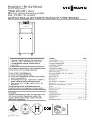
SL 80-399 MODULATING GAS BOILERminutes, for the initial cycle) of the higher load set<strong>ting</strong> before switch-over to thesimultaneously calling load, e.g. DHW with priority set to 80 will run for approx.35 min. before switching to a clashing load set with priority 45. Following suchinitial cycle, the clashing loads will switch back <strong>and</strong> forth after further 10 min.intervals pending satisfac<strong>tion</strong> of one or both loads.To cause repeated unequal run times (for example, constant 35 vs 5 min. runs) itis necessary to integrate an external load removing relay or timer on one of theheat calls (contact the Factory for details).2.6.2 Reset Hea<strong>ting</strong>The boiler offers Outdoor Reset control as st<strong>and</strong>ard equipment; this coordinatesthe control of boiler supply water temperature for space hea<strong>ting</strong> with the outdoortemperature. Outdoor Reset offers enhanced comfort <strong>and</strong> efficiency by usingvariable water temperatures to compensate for the differing rates of heat loss thata building faces as outdoor temperature changes. At any outdoor temperatureabove the coldest day expected, it automatically uses lower hea<strong>ting</strong> temperaturesthan would otherwise be used. This saves energy without sacrificing comfort.Figure 31: Outdoor reset curvesWhen applied within a condensing boiler, outdoor reset offers direct <strong>and</strong>significant combus<strong>tion</strong> efficiency benefits by allowing generally lower circula<strong>ting</strong>water temperature. This provides cooler return water to the boiler, promo<strong>ting</strong>more condensa<strong>tion</strong> (= energy capture).Contacts are provided for connec<strong>tion</strong> of an outdoor sensor (a tekmar 070 orsimilar sensor is shipped with each boiler) to be placed in an appropriate outdoorposi<strong>tion</strong>. The temperature management algorithm flexes the boiler supplytemperature according to characterized hea<strong>ting</strong> curves that are automaticallycalled up through the load declara<strong>tion</strong> process. Curves are provided for eachof the radia<strong>tion</strong> terminal types offered - e.g. high or low mass radiant floor, airh<strong>and</strong>ler, finned tube baseboards etc.In an “open loop” reset system, a room or zone thermostat is used to send a callfor heat over a 24VAC lead; this opens the respective zone valve, <strong>and</strong> signalsthe boiler to fire using onward leads to the boiler’s dry contacts (use one of thepairs marked “Therm 1, 2 or 3” on the Sensor Block terminal strip. Gang suchleads in parallel from multiple zone valves for single connec<strong>tion</strong> to the boiler.BOILER SYSTEMS AND OPERATION2-7
SL 80-399 MODULATING GAS BOILERNote that typical room thermostats simply provide a call for heat, they do notcontrol the circula<strong>ting</strong> water temperature from the boiler in an open loop resetsystem. Adjustment of a room thermostat from 23°C to 30°C will make no furtherdifference to the delivered temperature if the floor slab has stabilized at the boilertemperature served up by the reset curve.Where Outdoor Reset is applied without the indoor sensor feedback op<strong>tion</strong>, somemanual adjustment may be required to achieve the desired comfort level. Fineadjustment can be made at the keypad using the Indoor Setpoint Temperaturevariable, located as Line 1 in the User screen. To increase heat (e.g. from 72°F to73°) - move the Indoor value upward (warmer) from the level otherwise chosen.This shifts the posi<strong>tion</strong> of the reset curve, will amend the boiler water temperatureby a similar amount. Do not adjust the Design Indoor Temp. value - a movementupward in concert with Line 1 adjustment will have the effect of neutralizing theintended effect.An op<strong>tion</strong>al indoor temperature feedback routine can be activated (with field<strong>inst</strong><strong>alla</strong><strong>tion</strong> of an indoor sensor, connected to the contacts located on thecontroller) to automate adjustment of the Outdoor Reset routine.The key inputs on initial set up are (1) Design Outdoor Temperature – the coldestexpected weather typically experienced at the <strong>inst</strong><strong>alla</strong><strong>tion</strong> site; (2) the DesignSupply Temperature – the desired boiler <strong>opera</strong><strong>ting</strong> level to occur at that coldestday; <strong>and</strong> (3) the Design Indoor Temp. - this is the value that anchors the resetcurve. The Indoor Set Point Temp. variable is the primary means for the user to“bias” the outdoor reset routine to add or reduce heat.If outdoor reset is selected <strong>and</strong> there is no signal received from the sensor,the controller assigns a provisional 0°C value <strong>and</strong> will adopt the appropriatetemperature target from the relevant reset curve.See Sec<strong>tion</strong> 2.7 Set Up & Load Defini<strong>tion</strong> for activa<strong>tion</strong> procedure.2.6.3 Variable Speed PumpingThe controller provides an electrical signal (4-20mA) for connec<strong>tion</strong> to pumps thatare capable of using this signal to vary their rota<strong>tion</strong>al speed.ΔT° management across the majority of the boiler’s <strong>opera</strong><strong>ting</strong> range can beachieved with proper piping <strong>and</strong> control configura<strong>tion</strong>, but this feature is currentlynot supported without direct consulta<strong>tion</strong> with the IBC Factory.Where a conven<strong>tion</strong>al pump is correctly wired in accordance with the wiringdiagram, the pump will <strong>opera</strong>te at a single, high speed.2.6.4 Temperature SetbackFor hea<strong>ting</strong> loads declared as Space Hea<strong>ting</strong> (e.g. with Outdoor Reset) <strong>and</strong>/or DHW (where a thermistor probe is used), there are provisions for enteringtemperature setback intervals. During the setback period, the boiler supplywater temperature target is adjusted from the pre-set fixed or floa<strong>ting</strong> (withOutdoor Reset) levels. There is a simultaneous movement in the Indoor SetpointTemperature or DHW Tank Setpoint, to yield a consistent spread <strong>and</strong> avoidundesirable cycling. Normally users would apply this feature to achieve fuelsavings during night-or-away hours. It is also possible to use the feature toset forward (up) the temperature; this may be of use for certain commercialapplica<strong>tion</strong>s where short-term high temperature DHW service is desired.Up to 56 events / week can be programmed for each eligible load – for example,DHW can be set back twice <strong>and</strong> returned (twice) each day. The routine can beapplied by specific day (Mon-Sun).2-8INSTALLATION AND OPERATION INSTRUCTIONS
SL 80-399 MODULATING GAS BOILERThe automated setback feature cannot be applied to setpoint loads, includingDHW with simple aquastat control. This is due to the lack of linkage with thethermostat; setback without linkage could lead to unacceptable cycling.Access is via the User Setup screen.2.6.5 Unoccupied ModeUsers can further reduce energy consump<strong>tion</strong> by switching the boiler to theunoccupied mode during holidays or other away periods.While in the Unoccupied mode, the DHW load is turned off, while Space Hea<strong>ting</strong>loads for which Outdoor Reset is activated will drop both the circula<strong>ting</strong> water <strong>and</strong>the indoor setpoint temperature parameters to 50°F. Set Point controlled loadsare not adjusted through this process, to avoid the potential for boiler cycling asthere is no linkage with the relevant thermostat.On the main User Setup Menu, select “Occupancy Status”, then toggle betweenOccupied (top button) <strong>and</strong> Unoccupied (lower button) as desired.2.6.6 Summer ShutdownDuring the Installer set up process, a cut-off level for outdoor temperature can beselected - to curtail any further space hea<strong>ting</strong>. This is typically used to turn off anOutdoor Reset enabled load once the outdoor temperature reaches a thresholdlevel e.g. 60°F. The load will be automatically reactivated once the weatherreturns to levels below the selected threshold. Use of this feature with a value 5°- 10°F below the Indoor Setpoint Temperature is strongly recommended to avoidshort cycling of the boiler during very marginal hea<strong>ting</strong> condi<strong>tion</strong>s.From the main Installer Setup Menu, select “Heat Load Configura<strong>tion</strong>”, then“Configure Load (use the load number tagged as Space Hea<strong>ting</strong>)”, <strong>and</strong> dropdown to “Summer Shutdown”. Press Enter to select, then use the keys to movethe threshold temperature to the desired level, <strong>and</strong> press the centre key again torecord. The controller must receive a valid signal from the tekmar 070 outdoorsensor, supplied with the boiler, to <strong>opera</strong>te.2.6.7 Remote / Subordinate ModeInstallers have the op<strong>tion</strong> of placing the control of the boiler under an externalelectronic controller (such as a tekmar 265). Connec<strong>tion</strong>s are provided toreceive a 0-10vDC or 4-20 mA signal for throttle management. The defaultconfigura<strong>tion</strong> is 4-20mA; to switch over to 0-10V, remove the electrical boxcorner cover to provide access to the slotted clearance hole on the lower rightcorner of the control module; use needle-nose pliers to move the plastic jumpertab from the right two terminals to the left two terminals accessible throughthe slotted clearance hole. Where the IBC controller senses a signal on theremote connec<strong>tion</strong>s, it automatically subordinates its internal throttle logic, <strong>and</strong>adopts the external signal. In such slave mode, temperature management isalso surrendered to the external controller’s sensors. The <strong>inst</strong>aller only entersMaximum Boiler Supply <strong>and</strong> On/Off Differential temperatures; the boiler willrespond to these as high limit switches.From the main Installer Setup Menu, select “Define Load (with desired #)”, thenlocate <strong>and</strong> enter “External Control”. Next, configure the load with the Maximum<strong>and</strong> Differential temperature values.BOILER SYSTEMS AND OPERATION2-9
SL 80-399 MODULATING GAS BOILER2.7SET UP & LOAD DEFINITIONAfter the boiler is powered up, the <strong>inst</strong>aller can use the keypad <strong>and</strong> display tocharacterize the applica<strong>tion</strong>, as follows:1. In the St<strong>and</strong>by mode, start by pressing any key to call up the Main Menu.2. Using the direc<strong>tion</strong>al keys, move the cursor to Installer Setup, then depressthe centre (Enter) key. See Sec<strong>tion</strong> 2.4.5. Passwords if these are in use ordesired.3. Select Date & Time (<strong>and</strong> Enter), then move the cursor about to adjust time(on a 24:00 hour basis), date <strong>and</strong> invoke Daylight Savings if appropriate. Usethe upper key to increase a value (e.g. date, time, temperature), the bottomkey to reduce. Note that it is often possible to move in steps of 10 or 100 bymoving the cursor right or left once a field has been selected for adjustment.Hit the Enter key to record the desired / amended informa<strong>tion</strong> after eachvalue has been selected.4. Use the left-most key to step back to the Installer Setup screen, <strong>and</strong> selectHeat Load Configura<strong>tion</strong> for input of the load characteristics.5. Each of the boiler’s 3 Load posi<strong>tion</strong>s can be configured for any type ofhea<strong>ting</strong>. VFC boilers are factory shipped with default set<strong>ting</strong>s as follows:Load 1 set as Space Hea<strong>ting</strong> or Reset Hea<strong>ting</strong>, with High Mass RadiantFloor set as the terminal type; Load 2 as Set Point; <strong>and</strong> Load 3 as DHW. Thefactory defaults can be changed using the Define Load 1-2-3 lines to reversethe order, turn off a Load or do whatever the <strong>inst</strong>aller desires.6. Once the appropriate Loads are set, use the left-h<strong>and</strong> key to move back to theSetup Hea<strong>ting</strong> Loads screen, then move down to Configure Load 1 (<strong>and</strong> hit enter).7. The screen will display the input fields appropriate to the nature of the loadselected, e.g. Design Outdoor Temp. for a Space Hea<strong>ting</strong> (or Reset Hea<strong>ting</strong>)load. Note: these fields are pre-loaded with default values that are to bealtered to reflect the desired parameters.8. For reset loads, the initial selec<strong>tion</strong> to be made addresses the “emitter” type– choices include H(high) Mass Radiant, L(ow) Mass Radiant, Baseboard, AirH<strong>and</strong>ler etc. An appropriate reset curve is called up through this procedure.Reset loads carry a default value for Design Outdoor Temp. of -10°F (-23°C).Raise or lower this as appropriate – e.g. for Vancouver or Seattle, use 19°to 25°F, while for Edmonton or Fargo -30°F would be more appropriate.Note: - for some users, this adjustment may seem counter-intuitive. Movingthe set<strong>ting</strong> toward a colder design value will have the effect of reducing theboiler’s target temperature for any given weather, because a given currentcondi<strong>tion</strong> is relatively warmer than the designated “coldest” day.Moving down the screen, set the Design Supply Temperature – the targetedtemp. for circula<strong>ting</strong> water on the coldest day. For an in-slab radiant floorthis would typically be 125°F (50°C). For finned tube baseboards typicallydriven at 180°F, try 160°F max. <strong>inst</strong>ead, to promote combus<strong>tion</strong> efficiency.For air h<strong>and</strong>lers, try running 20°F lower than typically used. Of course, theappropriate set<strong>ting</strong> will depend on the characteristics of the emitter <strong>and</strong> thebuilding but in general the SL modula<strong>ting</strong> boiler’s large throttle turndown willallow better average temp. control, permit<strong>ting</strong> lower maximums.9. For Reset Loads, move down the screen again to display more lines;2-10INSTALLATION AND OPERATION INSTRUCTIONS
SL 80-399 MODULATING GAS BOILERUse the Summer Shutdown field to enter a threshold temperature for theavoidance of hea<strong>ting</strong> during warmer times. This is typically set at 60° to 65°Fso as to eliminate excessive boiler cycling in marginal hea<strong>ting</strong> condi<strong>tion</strong>s.Use the Minimum Temp. field to optimize boiler run times on low mass loads.Finned tube baseboards sink very little heat when <strong>opera</strong>ted below 100°F;applica<strong>tion</strong> of a “full reset curve” (e.g. 160°F right down to a 70°F roomtarget) would cause boiler cycling in light-to-moderate hea<strong>ting</strong> condi<strong>tion</strong>s.Set baseboard minimums at 100-120°F <strong>and</strong> aim for 4 or less cycles/hr. Aminimum set<strong>ting</strong> can also be used to enhance home comfort with single orexcessive speed air h<strong>and</strong>lers to avoid the cool blast effect. Set the lowestpossible level for combus<strong>tion</strong> efficiency.10. For all loads, select <strong>and</strong> enter a Maximum allowable temperature <strong>and</strong> on/off Supply Differential Temp. Note these values must be input; they are notautomatically assigned as done within some boiler controls. Ensure theMaximum takes account of the construc<strong>tion</strong> <strong>and</strong> safety requirements of eachapplica<strong>tion</strong> – e.g., 140°F max. for typical in-slab radiant floor, for avoidance ofthermal stress. The Differential shall be set to offer a reasonable temperaturecontrol range (suggested values: 20°F for high mass radiant // 30°F for lowmass baseboards // 16°F for DHW). Ensure that the spread between theTarget <strong>and</strong> Maximum temps is greater than one half of the Differential (e.g.for a radiant floor Design Supply Temperature of 125°F <strong>and</strong> a Maximum of140°F, a differential of 20°F (half of which is 10°F) fits nicely.11. Avoid situa<strong>tion</strong>s where the Maximum is close or below the potential Target, orthe boiler will cycle off its (software) water high limit.12. Priority:- where more than one load is present, it is critical that a value beentered to allow reasonable load scheduling (see Sec<strong>tion</strong> 2.6.1).13. At the lower end of the Load 1-2-3 setup screen, there are 4 lines availablefor “mapping” of sensor inputs.. For example, “Indoor Temp. from …..Indoor”indicates that the boiler will look for a signal from an indoor sensor on theIndoor Sensor wiring contacts. Failing a valid signal, the screen will display“Indoor Temp. …..Open”, <strong>and</strong> there will be no effective indoor trim of thereset curve. These lines do not require amendment at most <strong>inst</strong><strong>alla</strong><strong>tion</strong> sites.The mapping feature allows reassignment of the sensor contacts to supportnon-st<strong>and</strong>ard func<strong>tion</strong>s. For example, re-alloca<strong>tion</strong> of the Water Temp. signalfrom “(boiler) Outlet” to “Secondary Loop” will allow the throttle managementroutine to manage a secondary loop temperature rather than the boiler’s owndirect supply temperature. Use this when injec<strong>ting</strong> into a commercial hea<strong>ting</strong>:cooling loop. Another possibility: two separate reset channels – each with itsown indoor trim. Sensor ports open for such re-assignment are DHW, Indoor,Outdoor <strong>and</strong> Secondary Loop.14. The final 3 lines are for the motorized mixing valve op<strong>tion</strong>. See separatedocumenta<strong>tion</strong> for this.15. To compensate for altitude at the <strong>inst</strong><strong>alla</strong><strong>tion</strong> site, use the Altitude adjustmentfeature, found in the front Installer Setup menu (several lines below “HeatLoad Configura<strong>tion</strong>”. Key in the altitude – in hundreds of feet above sealevel. For example, an <strong>inst</strong><strong>alla</strong><strong>tion</strong> at 2,860 feet should be entered as “29” (asrounded to the nearest hundred).16. Two lines below Altitude adjustment is the field for amendment of the primarypump heat purge time. To shorten the 5 minute post-firing period, reduce the300 second interval to as low as 60 sec. Similar adjustment of secondarypump run time can be made in the Heat Load Configura<strong>tion</strong> / Configure Load1,2,3 fields (down to zero sec.= off).BOILER SYSTEMS AND OPERATION2-11
SL 80-399 MODULATING GAS BOILER17. Upon comple<strong>tion</strong> of the input of load parameters, use the left button to stepback through the menu system to return to the Opera<strong>ting</strong> Status screen.18. To enact the control arrangements as input, it is necessary that the pipingstructure <strong>and</strong> system wiring are configured appropriately (refer to Sec<strong>tion</strong>1.6.2 Inst<strong>alla</strong><strong>tion</strong> Rules, page 1-20 for piping layouts <strong>and</strong> the WiringSchematics on pages 6-4 <strong>and</strong> 6-5). Ensure that DHW aquastat or thermistorprobe leads, thermostat <strong>and</strong> pump (or zone valve) leads are connected attheir respective contact points on the terminal block.19. Forced shutdown: – use the Heat Load Configura<strong>tion</strong> screen to switch offload(s) to remove a call for heat, if no other means are readily available.Simple removal of power to boiler is to be avoided – this interruptsthe moisture management routine. Treat the unit as you would treat acomputer, allowing an orderly shutdown.2-12INSTALLATION AND OPERATION INSTRUCTIONS
SL 80-399 MODULATING GAS BOILER3.0STARTUP AND COMMISSIONING3.1 LIGHTING AND SHUTTING DOWNTHE BOILERSTARTUP AND COMMISSIONING3-1
SL 80-399 MODULATING GAS BOILER3.2 PRIOR TO START-UPWARNINGFill trap with water beforeboiler is first fired to preventexhaust fumes from enteringroom. Never <strong>opera</strong>te theboiler unless the trap is filledwith water.Failure to comply will resultin severe personal injury ordeath.3.2.1 Pre-Igni<strong>tion</strong> Checks1. Ensure ven<strong>ting</strong> system is complete <strong>and</strong> seal tested. Confirm any commonven<strong>ting</strong> system at the <strong>inst</strong><strong>alla</strong><strong>tion</strong> site is isolated <strong>and</strong> independent of the SLboiler, that any holes left from removal of a previous boiler have been sealed,<strong>and</strong> that any resizing of the old flue has been done. Fill condensa<strong>tion</strong> trap.2. Check water piping system is fully flushed <strong>and</strong> charged, <strong>and</strong> that all air hasbeen discharged through loosened bleed caps. Note it is possible to switchall pumps on/off from the keypad – without a call for heat. This greatlysimplifies system filling <strong>and</strong> air bleeding (go to Installer Setup, drop downto Pump Purge <strong>and</strong> toggle to On. When complete, return to Off, or this willautomatically occur with a call for heat). Use a minimum water pressure of 12psig. And confirm pressure relief valve is <strong>inst</strong>alled <strong>and</strong> safely drained.3. Perform a final check of electrical wiring.4. Using a manometer, check to see that adequate gas pressure is presentat the inlet gas supply test port. Requirements are minimum 5” w.c <strong>and</strong>maximum 14” w.c.3.2.2 Test Igni<strong>tion</strong> Safety ShutoffError displayed after tes<strong>ting</strong> igni<strong>tion</strong>safety shut offWith the boiler in <strong>opera</strong><strong>tion</strong>, test the igni<strong>tion</strong> system safety shutoff device byshut<strong>ting</strong> the manual gas valve immediately outside the boiler case. Ensureboiler has shut off <strong>and</strong> the appropriate Error informa<strong>tion</strong> is displayed on the LCDscreen. To restart boiler, reset power.3.3commissioningThe SL 80-399 modula<strong>ting</strong> boiler is factory calibrated to <strong>opera</strong>te with naturalgas (or propane if so ordered) at sea level. The relevant valve adjustmentscrews have been factory sealed using Loctite thread-lock compound, whichcan be broken where required. However, no mixture adjustment shall beperformed unless done by a qualified technician using properly func<strong>tion</strong>ingcombus<strong>tion</strong> analyzing equipment.Inlet gas supply pressure test portUpon initial set up, the <strong>inst</strong>aller can enter the site eleva<strong>tion</strong> to compensatefor altitude. Without such interven<strong>tion</strong>, the gas valve will automatically de-ratethe maximum input in accordance with the density altitude, by approximately 2%per 1,000’ above sea level. The gas valve’s zero governor will ensure that thegas:air mixture is not affected at altitude.To verify the proper <strong>opera</strong><strong>tion</strong> of the gas valve in the field, the following procedurecan be carried out by a qualified technician (see Figure 28).Manifold pressure test port3-21. with a small (1/8" or 3 mm) flat screwdriver, open the manifold pressuretest port by turning its centre- screw 1 full turn counterclockwise. Attach amanometer between the manifold pressure test port <strong>and</strong> the reference line.2. Allow the boiler to ignite / run aga<strong>inst</strong> a large load, to maintain high fire3. With the boiler at maximum output, use a 2 mm hex key to adjust the zerooffset(see Figure 28, “A”) as required to achieve 0” wc. This adjustment isonly necessary if this screw has been tampered with.INSTALLATION AND OPERATION INSTRUCTIONS
SL 80-399 MODULATING GAS BOILERDANGERMaking adjustments tothe IBC gas valve withouta properly calibrated gascombus<strong>tion</strong> analyzer <strong>and</strong> bypersons who are not trained<strong>and</strong> experienced in its useis forbidden. Failure to usean analyzer can result in animmediate hazard.4. With a combus<strong>tion</strong> analyzer probe in the flue gas test port, turn the Gas:AirRatio Adjustment screw (see Figure 28, “B”) to achieve 25% excess air(corresponding CO2 values are 9.4% for natural gas <strong>and</strong> 10.7% for propane).This screw offers very fine adjustment, <strong>and</strong> may require several turns.Note: This screw has significant backlash. When changing direc<strong>tion</strong> of turn,it may take up to a full turn before any change is indicated on the analyzerreading. Clock the gas meter to confirm full maximum ra<strong>ting</strong> plate input.5. To confirm or adjust the minimum fire level set<strong>ting</strong>s, Re-define the load as“Manual Control”. Use Heat Output in “Configure Load x” to control the outputas needed.6. At the minimum firing rate, adjust the zero-offset screw (see Figure 28, “A”)to obtain 25% excess air. It may be necessary to reduce the output in stagesif this adjustment has been tampered with.7. Turn boiler off by removing the call for heat (use the Heat Load Configura<strong>tion</strong>screen to turn load to off if no other ready means available), then remove themanometer connec<strong>tion</strong>s, <strong>and</strong> turn the centre-screw in the manifold pressuretest port 1 full turn clockwise. Ensure fully closed, but not over-tightened.Zero-offset adjustment screwRemoval of flue gas test port plugInser<strong>tion</strong> of flue gas analyzer probeGas:Air ratio adjustment screwFlue gas test port plugFigure 32: Gas Valve <strong>and</strong> Pressure Reference SystemSTARTUP AND COMMISSIONING3-3
SL 80-399 MODULATING GAS BOILERNOTEThe safety warning regardingburner refractory on page4-2 of this manual must beobserved.3.3.1 Gaining access to combus<strong>tion</strong> chamber, burnerremoval <strong>inst</strong>ruc<strong>tion</strong>s1. Remove fan <strong>and</strong> gas valve assembly. See “Fan <strong>and</strong> gas valve removal<strong>inst</strong>ruc<strong>tion</strong>s” on page 4-6 of this manual.2. Disconnect the igniter cable <strong>and</strong> move it out of the way.3. Remove the two screws that secure the igniter to the lid using a # 2 Phillipsscrewdriver.4. Carefully remove the igniter by sliding it straight up.5. Remove the igniter gasket <strong>and</strong> place parts on a clean dry area.6. Remove the 6 hex nuts that attach the heat exchanger lid to the heatexchanger. A 10 mm open end wrench or socket will be required.7. With a permanent marker or equivalent, make an alignment mark betweenthe lid <strong>and</strong> heat exchanger.8. Before removing the lid, it is important to be posi<strong>tion</strong>ed directly above it to ensurea straight up extrac<strong>tion</strong>. Failing to do this may result in refractory damage.9. Slowly lift the lid-burner assembly off the heat exchanger. The refractoryshould remain in place in the combus<strong>tion</strong> chamber shoulder. Note thatthere is less than 1/8” (3 mm) clearance between the burner walls <strong>and</strong> therefractory. Care must be observed to ensure minimal contact between theseparts to prevent refractory cracking.10. Place the lid with the burner attached, on a clean dry area.11. With a permanent marker or equivalent, make an alignment mark on therefractory lining it up with the same mark made earlier between the lid <strong>and</strong>heat exchanger.12. Carefully remove the refractory <strong>and</strong> place in a clean dry area.13. If burner needs to be removed, gradually loosen up the 8 screws that securethe burner to the heat exchanger lid using a #2 Phillips screwdriver. Removescrews <strong>and</strong> burner.Re-assembly1. Inspect burner gasket. Look for cracks, deteriora<strong>tion</strong> or signs of gas bypass.Replace if necessary.2. Place heat exchanger lid on a flat surface <strong>and</strong> posi<strong>tion</strong> the gasket on the lid,aligning it with the screw holes.3. Install the burner in place with its 8 screws, tightening the screws gradually <strong>and</strong>in a cross sequence. Do not over tighten, h<strong>and</strong> tight plus 1/2 turn should besufficient to maintain a good seal <strong>and</strong> prevent deforma<strong>tion</strong> of the burner flange.4. Inspect refractory for cracks, degrada<strong>tion</strong> <strong>and</strong> flatness. If in doubt, replacewith a new one.5. If <strong>inst</strong>alling a new refractory, first place it onto the lid, aligning it at the igniterhole, then make an alignment mark on the refractory to coincide with thepreviously made line on the lid.6. Carefully insert refractory onto heat exchanger combus<strong>tion</strong> chamber, usingthe alignment marks for proper posi<strong>tion</strong>ing.7. Ensure that the lid (orange) gasket is in place <strong>and</strong> flat.8. Carefully insert the lid-burner assembly straight down ensuring limited contactbetween burner <strong>and</strong> refractory <strong>and</strong> observing the alignment markings.9. Install the 6 hex nuts to secure the lid in place, tighten by h<strong>and</strong>, then anextra 1/2 turn. Cau<strong>tion</strong>! Over-tightening these nuts will cause lid to warp <strong>and</strong>possibly leak fumes or flames.10. Re-<strong>inst</strong>all igniter, tightening its screws by h<strong>and</strong>, then an extra 1/2 turn.11. Re-attach igniter wire to igniter.3-4INSTALLATION AND OPERATION INSTRUCTIONS
SL 80-399 MODULATING GAS BOILER4.04.1MAINTENANCEBOILER MAINTENANCECAUTIONThe owner is responsible forgeneral care of the boiler.Improper maintenance ofthe boiler may result in ahazardous condi<strong>tion</strong>.CAUTIONLabel all wires prior todisconnec<strong>tion</strong> when servicingcontrols. Wiring errorscan cause improper <strong>and</strong>dangerous <strong>opera</strong><strong>tion</strong>.WARNINGFill trap with water beforeboiler is first fired to preventexhaust fumes from enteringroom. Never <strong>opera</strong>te theboiler unless the trap is filledwith water.Failure to comply will resultin severe personal injury ordeath.WARNINGWhenever the burner isremoved for inspec<strong>tion</strong> orboiler servicing, the sealinggaskets must be examined<strong>and</strong> replaced if damaged.Upon re-assembly, anapproved leak test solu<strong>tion</strong>must be applied around theburner flange sealing area toensure there is no leakage ofcombustible gas/air premix.4.1.1 General Care• Keep combustible materials <strong>and</strong> flammable liquids <strong>and</strong> vapours away from theboiler.• Keep vent terminals clear of obstruc<strong>tion</strong>s (snow, dirt, etc.).4.1.2 Inspec<strong>tion</strong>Inspec<strong>tion</strong> of the boiler is to be performed annually by a qualified servicetechnician.4.1.3 Ven<strong>ting</strong>• Check vent terminals for <strong>and</strong> remove any obstruc<strong>tion</strong>s (e.g. leaves, dust,other debris).• Check, <strong>and</strong> clean or replace intake air filters or screens as required.• Check for holes or leaks in ven<strong>ting</strong>. Replace ven<strong>ting</strong> as needed.• Examine for any signs of moisture caused by swea<strong>ting</strong> intake air pipes;insulate as required.4.1.4 Condensate Traps• Condensate trap must be examined every two months to see if cleaning isnecessary (refer to trap cleaning <strong>inst</strong>ruc<strong>tion</strong>s on page 1-14 of this manual).Ensure that trap has been re-filled completely before firing boiler.• If condensate neutraliza<strong>tion</strong> is used, check pH level of condensate discharge.4.1.5 Burner• Annually, remove burner to inspect for extent of fouling (refer to burnerremoval <strong>and</strong> reassembly <strong>inst</strong>ruc<strong>tion</strong>s on page 3-4, adjacent page). Blowclear using compressed air. Evaluate the magnitude of clearing required, <strong>and</strong>establish a reasonable burner inspec<strong>tion</strong> schedule. Some boiler / loca<strong>tion</strong>smay call for annual service, others showing clean burners will only needatten<strong>tion</strong> every 2 – 5 years. Consider adding air filtra<strong>tion</strong> if burner requirescleaning every year. In alternate years, visually inspect burner through sightglass. Ensure flame is stable <strong>and</strong> without excessive fluttering. Normal flamepattern is evenly distributed over the burner surface.• If burner is <strong>opera</strong><strong>ting</strong> improperly, remove <strong>and</strong> clean or replace. Use a CO2analyzer to determine proper combus<strong>tion</strong>. CO2 level should be 9.4% (fornatural gas) or 10.7% (propane).MAINTENANCE4-1
SL 80-399 MODULATING GAS BOILERWARNINGThe IBC heat exchanger has asmall amount of combus<strong>tion</strong>chamber insula<strong>tion</strong> (refractory),which contains ceramic fibers.When exposed to extremely hightemperatures, the ceramic fibers,which contain crystalline silica,can be converted into cristobalite- which is classified as apossible human carcinogen.Care should be taken to avoiddisturbing or damaging the refractory.If damage occurs, contactthe factory for direc<strong>tion</strong>s.Avoid breathing <strong>and</strong> contact withskin <strong>and</strong> eyes <strong>and</strong> follow theseprecau<strong>tion</strong>s:1. For condi<strong>tion</strong>s of frequentuse or heavy exposure, respiratorprotec<strong>tion</strong> is required. Referto the “NIOSH Guide to theSelec<strong>tion</strong> <strong>and</strong> Use of ParticulateRespirators Certified under 42CFR 84” for selec<strong>tion</strong> <strong>and</strong> use ofrespirators certified by NIOSH.For the most current informa<strong>tion</strong>,NIOSH can be contacted at1-800-356-4676 or on the web atwww.cdc.gov/niosh.2. Wear long sleeved, loose fit<strong>ting</strong>clothing, gloves <strong>and</strong> eyesprotec<strong>tion</strong>.3. Assure adequate ventila<strong>tion</strong>.4. Wash with soap <strong>and</strong> waterafter contact.5. Wash potentially contaminatedclothes separately fromother laundry <strong>and</strong> rinse washingmachine thoroughly.6. Discard used insula<strong>tion</strong> in anair tight plastic bag.NIOSH stated first aid:Eye contact - Irrigate <strong>and</strong> washimmediately.Breathing - Provide fresh air.4.1.6 Heat ExchangerDuring annual inspec<strong>tion</strong> (with the burner removed), examine the heat exchangerfor signs of contamina<strong>tion</strong> <strong>and</strong> clean if neccessary. In areas of poor gas quality,there may be a buildup of black plaque (typically sulfur). Other fouling agents:airborne dust, debris <strong>and</strong> volatiles.Refer to burner removal <strong>inst</strong>ruc<strong>tion</strong>s on page 3-4 for access to combus<strong>tion</strong>chamber <strong>and</strong> heat exchanger. Note that the safety warning regarding burnerrefractory on page 4-2 on this page must be observed.4.1.7 PumpCheck that the pump is on in normal <strong>opera</strong><strong>tion</strong> <strong>and</strong> that the water Δ°T isreasonable for a given firing rate (e.g. 10°F between supply <strong>and</strong> return whenfiring at 200,000 Btu/hr.).4.1.8 Gas PipingCheck for damage or leaks <strong>and</strong> repair as needed.4.1.9 Control Module• Check that boiler <strong>opera</strong><strong>tion</strong> is consistent with the steps in Sec<strong>tion</strong> 2.5Sequence of Opera<strong>tion</strong>.• Check that water temperature targets <strong>and</strong> setpoint is satisfactory <strong>and</strong> havenot been adversely amended.• Check the <strong>opera</strong><strong>ting</strong> history using the screen: - use Installer Setup // Logs, toscan for hours of service, cycles per hour, <strong>and</strong> any logged errors. One methodis to use the graphical presenta<strong>tion</strong> of the duty cycle by load – go to Logs,move the cursor to a load <strong>and</strong> push “Enter” to access. This gives a profile ofthe boiler’s duty cycle by throttle level.• If a problem exists with the control, consult troubleshoo<strong>ting</strong> guide.4.1.10 Water• Check water pressure <strong>and</strong> temperature. There should be no noticeablechange if boiler is func<strong>tion</strong>ing normally. Check for any noise in the system.• Check water piping for damage or leaks <strong>and</strong> repair as needed.• Check for 12-15 psig in normal <strong>opera</strong><strong>tion</strong>, <strong>and</strong> look to ensure pressure doesnot run up toward 30 psig at high temperature. If pressure rises sharply,consider replacement of expansion tank. Check also for noise at high fire,which may signal water quality problems.• Check water piping for damage or leaks <strong>and</strong> repair as needed.• Water chemistry shall be of a quality generally accepted as suitable forhydronic applica<strong>tion</strong>s.• Ensure any direct “city fill” water connec<strong>tion</strong>s are left in the closed posi<strong>tion</strong> tominimize exposure to leaks <strong>and</strong> flooding.4.1.11 Freeze Protec<strong>tion</strong>Check freeze protec<strong>tion</strong>. Use only antifreeze made specifically for hydronicsystems. Inhibited propylene glycol is recommended. Antifreeze volume must notexceed 50% of the total volume of water in the system.4-2INSTALLATION AND OPERATION INSTRUCTIONS
SL 80-399 MODULATING GAS BOILERWARNINGDo not use automotive-typeethylene or other types ofautomotive glycol antifreeze,or undiluted antifreeze ofany kind. This may resultin severe boiler damage. Itis the responsibility of theInstaller to ensure that glycolsolu<strong>tion</strong>s are formulated toinhibit corrosion in hydronichea<strong>ting</strong> systems of mixedmaterials. Improper mixtures<strong>and</strong> chemical additives maycause damage to ferrous <strong>and</strong>non-ferrous components aswell as non-metallic, wettedcomponents, normally foundin hydronic systems. Ethyleneglycol is toxic, <strong>and</strong> may beprohibited for use by codesapplicable to your <strong>inst</strong><strong>alla</strong><strong>tion</strong>loca<strong>tion</strong>. For environmental<strong>and</strong> toxicity reasons, IBCrecommends only using nontoxicpropylene glycol.NOTEInstallers should inquire oflocal water purveyors as tothe suitability of their supplyfor use in hydronic hea<strong>ting</strong>systems.If water quality isques<strong>tion</strong>able, a local watertreatment expert mustbe consulted for tes<strong>ting</strong>,assessment <strong>and</strong>, if required,treatment.Alternatively, water or hydronicfluid of known quality can bebrought to the site.4.1.12 Boiler Treatment• Check consistency of any boiler treatment used, for appropriate mixture.Chemical inhibitors are consumed over time, lowering their density.• Verify proper <strong>opera</strong><strong>tion</strong> after servicing.4.1.13 Relief Valve - Maintenance <strong>and</strong> Tes<strong>ting</strong>The relief valve manufacturer requires that under normal <strong>opera</strong><strong>ting</strong> condi<strong>tion</strong>sa “try lever test” must be performed every two months. Under severe servicecondi<strong>tion</strong>s, or if corrosion <strong>and</strong>/or deposits are noticed within the valve body,tes<strong>ting</strong> must be performed more often. A “try lever test” must also be performedat the end of any non-service period.Test at or near maximum <strong>opera</strong><strong>ting</strong> pressure by holding the test lever fully openfor at least 5 seconds to flush the valve seat free of sediment <strong>and</strong> debris. Thenrelease the lever <strong>and</strong> permit the valve to snap shut.If the lever does not activate, or there is not evidence of discharge, discontinueuse of equipment immediately <strong>and</strong> contact a licensed contractor or qualifiedservice personnel.If the relief valve does not completely seal, <strong>and</strong> fluid continues to leak from thedischarge pipe - perform the test again to try <strong>and</strong> flush any debris that may belodged in the valve. If repeated tries fail to stop the leakage, contact a licensedcontractor or qualified service personnel to replace the valve.While performing a “try lever test”, a quantity of heat transfer fluid will bedischarged from the piping system <strong>and</strong> the system pressure will drop. This fluidmust be replaced. It is highly recommended that a system pressuriza<strong>tion</strong> unit,such as an Axiom Industries model MF200 be employed to refill <strong>and</strong> pressurizeyour system. Capture the discharged fluid in a container <strong>and</strong> recycle it byreturning it to the system feeder unit. This is particularly important when yoursystem contains treatment chemicals or glycol solu<strong>tion</strong>s. If the system employsplain water, the boiler auto fill valve must be turned on in order to recharge thelost fluid.CAUTIONBefore tes<strong>ting</strong> the relief valve,make certain the dischargepipe is properly connected tothe valve outlet <strong>and</strong> arrangedto contain <strong>and</strong> safely disposeof equipment discharge.MAINTENANCE4-3
SL 80-399 MODULATING GAS BOILER4.2GEOGRAPHY & COMPONENTSRemove top cover button boltsGas Inlet BlockTurn cover button Counter ClockWise to loosenLift top cover up at frontGas Valve BodyCover tilts back, then lift up <strong>and</strong> offTop cover lifts up <strong>and</strong> outFan Swirl plate (Air Inlet) between Fan <strong>and</strong>Gas ValveClear access to top componentsClear access to front componentsFan air pressure reference tube4-4INSTALLATION AND OPERATION INSTRUCTIONS
SL 80-399 MODULATING GAS BOILERBurner Flange BoltsTridicator Gauge on Supply RiserLow Water Cut-Off Module behind ControlPanelFan Flange BoltsManual Reset Water High Limit Switch onSupply Riser (red button is reset)Upper Vessel High Limit Switch onpressure vessel upper support bracketIgnitor Cable connected to IgnitorSight glass (inspec<strong>tion</strong> port)Low Water Cut-Off Probe on Supply RiserFlue Temperature Sensor on the ventbehind the Supply RiserMAINTENANCE4-5
SL 80-399 MODULATING GAS BOILER4.2.1 Fan <strong>and</strong> gas valve removal <strong>inst</strong>ruc<strong>tion</strong>s1. Turn off electric power <strong>and</strong> gas supply to the boiler.2. Ensure boiler cools down to ambient temperature. Do not drain the boilerunless freezing condi<strong>tion</strong>s are expected during this procedure.3. Remove front cover, then remove boiler upper-front cover by removing thetwo yellow thumbscrews at the top right <strong>and</strong> left corner of the boiler. No toolsare required.4. A ladder or step may be required to have a clear vertical view of the workarea. Do not attempt to reach from the front without a clear view, as damageto connectors, screws or refractory may occur.5. Unplug both upper <strong>and</strong> lower electrical connectors from the fan.6. Unplug the electrical connector from the gas valve by removing the 1/4”connector attaching screw.7. Posi<strong>tion</strong> the harnesses out of the way of the heat exchanger lid.8. Unplug the clear tube from the swirl plate pressure reference port.9. Remove the 4 hex head socket screws that attach the gas inlet block to thegas valve using a 4 mm hex (Allen) key or driver. These screws should befirst loosened up slightly in cross sequence to prevent deforma<strong>tion</strong> of thema<strong>ting</strong> parts.10. With the yellow flexible gas line still attached, the gas inlet block is now freeto move but should only be separated from the gas valve a maximum of 1inch (25 mm), which is sufficient for fan <strong>and</strong> gas valve removal. There isan o-ring <strong>inst</strong>alled between the gas inlet block <strong>and</strong> gas valve, <strong>and</strong> it shouldremain posi<strong>tion</strong>ed on the block’s groove. If it falls out it is important that it beposi<strong>tion</strong>ed back on the groove or saved for re-assembly.11. Remove the 4 hex nuts that attach the fan to the heat exchanger lid. A 10mm open end wrench or socket will be required.12. With the gas valve <strong>and</strong> swirl plate still attached, remove the fan by pullingstraight up ensuring that no wires are caught <strong>and</strong> that the gas line remains inplace. Place the removed components in a clean, dry area.13. If the fan is being replaced: With a permanent marker or equivalent, makean alignment mark between the fan <strong>and</strong> swirl plate adapter <strong>and</strong> use a 6 mmhex (Allen) key or driver, remove the 3 screws that attach the gas valve/swirlplate assembly to the fan.4-64.2.2 Fan <strong>and</strong> gas valve re-<strong>inst</strong><strong>alla</strong><strong>tion</strong>1. If the gas valve has been removed, reattach it to the swirl plate.2. Re-attach gas valve <strong>and</strong> swirl plate assembly onto fan observing thealignment marks made during disassembly.3. Ensure that fan (orange) gasket is in place.4. Re-<strong>inst</strong>all f an-gas valve assembly onto heat exchanger lid tightening the 4hex nuts by h<strong>and</strong> then an extra 1/2 turn.5. Re-plug both upper <strong>and</strong> lower fan harness connectors.6. Re-plug gas valve connector <strong>and</strong> tighten up retaining screw.7. If a new gas valve is being <strong>inst</strong>alled, remove the protective cover from thegas inlet now.8. Re-attach gas inlet block onto gas valve ensuring that the o-ring seal is inplace. If this O-ring is lost, it must be replaced with a factory supplied O-ring.9. Tighten up the 4 gas inlet block screws in cross sequence, first h<strong>and</strong> tight<strong>and</strong> then an extra 1/2 turn.10. Re-connect clear pressure reference tube onto swirl plate port.11. Open up gas valve <strong>and</strong> check for possible leaks.12. Return electric power to the boiler <strong>and</strong> perform start up routine.13. Check for gas or fumes leaks after 10 minutes of continuous <strong>opera</strong><strong>tion</strong>.INSTALLATION AND OPERATION INSTRUCTIONS
SL 80-399 MODULATING GAS BOILER5.0 TROUBLESHOOTINGThe troubleshoo<strong>ting</strong> sec<strong>tion</strong> is divided into 3 sec<strong>tion</strong>s:5.1 Preliminary Checks5.2 Electronic Components5.3 Troubleshoo<strong>ting</strong> GuideOften, a problem can be identified <strong>and</strong> solved through simple checks of thebasics: confirming the electrical power supply, gas flow <strong>and</strong> reset<strong>ting</strong> thethermostat control. To extend the cover of such preliminary checks, the boiler’scontrol module offers a clear visual display of the status of the various controlcircuit components.Should a problem remain unsolved after applying the preliminary checks,proceed to the detailed system review, using the Troubleshoo<strong>ting</strong> Guide. TheGuide covers potential error condi<strong>tion</strong>s as grouped into the following categories:5.3.1 Using Control Module Errors Displayed5.3.2 Igni<strong>tion</strong> Problems5.3.3 Cycling Problems5.3.4 Temperature Problems5.3.5 MiscellaneousBelow each sec<strong>tion</strong> is a list of Symptoms, Diagnoses, <strong>and</strong> Remedies.Also provided with this manual are a number of diagrams (see Sec<strong>tion</strong> 6.0) foruse with troubleshoo<strong>ting</strong> including:• Electrical Wiring Diagrams• Sequence of Opera<strong>tion</strong>s Flowchart• Boiler Component Layout Diagrams5.1Preliminary ChecksThe first step in troubleshoo<strong>ting</strong> this system should be a review of the Controller’sLCD screen. There are a number of diagnostic features incorporated in thesoftware that evaluate system integrity, display error condi<strong>tion</strong>s <strong>and</strong> provide initialsuggested remedial ac<strong>tion</strong>s (see Sec<strong>tion</strong> 2.5.6 Error Mode.)In addi<strong>tion</strong> to checking the display, the following list is a guideline fortroubleshoo<strong>ting</strong>:1. Confirm power to the boiler: check that control module display is on (e.g.display is lit).2. Check that boiler is not in a safety lockout.3. Ensure wiring is clean <strong>and</strong> secure.4. Check that gas is reaching the unit.5. Confirm water system is properly charged to 12 psig <strong>and</strong> pump isserviceable.TROUBLESHOOTING5-1
SL 80-399 MODULATING GAS BOILER5.2Electronic ComponentsThis sec<strong>tion</strong> details the method for troubleshoo<strong>ting</strong> the non-st<strong>and</strong>ard electroniccomponents on the boiler including the electronic differential air pressure sensor<strong>and</strong> the temperature sensors.5.2.1 Temperature SensorsThe resistance of the temperature sensors varies inversely with temperature. Totest, measure the temperature of the sensed environment <strong>and</strong> compare with thevalue derived from the measurement of the resistance (obtained by connec<strong>ting</strong> agood quality test meter capable of measuring up to 5,000 kΩ (5,000,000Ω) at thecontroller end of the sensor lead).To obtain a resistance reading, remove power to the boiler. For the supply water<strong>and</strong> vent temperature sensors, remove the wire leads by disconnec<strong>ting</strong> theirrespective Molex connectors. Place multi-meter probes into sensor’s femaleMolex connector socket. Do not apply voltage to the sensor (damage may result).Return water temperature sensorFor the return water temperature sensor, locate the blue 2-wire leads comingfrom the strap on sensor on the return pipe. Disconnect the Molex connectorlocated approx. 6" from the sensor. Place multi-meter probes into the sensor’sfemale Molex connector socket. Do not apply voltage.Supply water temperature sensor10KΩ sensors supplied with boiler2 x Water temperature sensors1 x Outdoor sensor (shown above)1 x Vent temperature sensorSee table #8 for resistance valuesTEMPERATURE RESISTANCE TEMPERATURE RESISTANCE°F °C Ω °F °C Ω0 -18 85,362 100 38 5,8285 -15 72,918 105 41 5,21010 -12 62,465 110 43 4,66515 -9 53,658 115 46 4,18420 -7 42,218 120 49 3,76025 -4 39,913 125 52 3,38330 -1 34,558 130 54 3,05035 2 29,996 135 57 2,75440 4 26,099 140 60 2,49045 7 22,763 145 63 2,25550 10 19,900 150 66 2,04555 13 17,436 155 68 1,85760 16 15,311 160 71 1,68965 18 13,474 165 74 1,53870 21 11,883 170 77 1,40375 24 10,501 175 79 1,28180 27 9,299 180 82 1,17285 29 8,250 185 85 1,07390 32 7,334 190 88 98395 35 6,532 195 91 903Table 8: Temperature Sensor resistance values5-2INSTALLATION AND OPERATION INSTRUCTIONS
SL 80-399 MODULATING GAS BOILER5.2.2 Fan/BlowerOpera<strong>ting</strong> power is provided by means of a separate 115 VAC connector at thebottom of the fan (white/black/green). Control of the fan is provided via a fourlead connector at the top of the fan. This connector feeds a PWM control signal(black wire) from the controller <strong>and</strong> provides a tachometer signal (white wire)back from the fan. Unplugging the control connector will cause the fan to go tohigh speed <strong>and</strong> trigger a “Blocked Vent Error” within 6 seconds if the boiler is<strong>opera</strong><strong>ting</strong>.Control wire plugLead Color Func<strong>tion</strong> Troubleshoo<strong>ting</strong>RedBlueBlack35 VDC Positive powerterminal35 VDC Negative powerterminalSignal from controllerFan will only <strong>opera</strong>te at max.speed if disconnected.Fan will only <strong>opera</strong>te at max.speed if disconnected.Fan will only <strong>opera</strong>te at max.speed if disconnected.White Fan tach. 2 pulses/rev (freq x 30=rpm)Table 9: Fan Opera<strong>tion</strong>5.2.3 Differential Air Pressure SensorUnplug to run fan full speedGo to the Advanced Diagnostics screen, <strong>and</strong> with the fan off (“Fan Duty Cycle =0) look for a Fan Pressure reading of 102 +/-5. Next check with fan in <strong>opera</strong><strong>tion</strong>,<strong>and</strong> look for an increased Fan Pressure value. In normal <strong>opera</strong><strong>tion</strong>, the FanPressure reading should move toward the Required Pressure value. A backwardmovement in Fan Pressure indicates the clear vinyl air pressure line has beenconnected to the wrong port on the sensor body.Removing circuit board terminalcoverCircuit boardFigure 29 (right): Testpoints on circuit boardfor air pressure sensorvoltage readingsRemove terminal plugs, then circuitboard coverTROUBLESHOOTING5-3
SL 80-399 MODULATING GAS BOILERNext, confirm that the circuit is properly powered. The supply voltage to thesensor should be 13.8 VDC; to check, the simplest technique is to measure thecircuit on the face of the controller circuit board (vs. an attempt to splice into theharness / connectors). See previous page for a presenta<strong>tion</strong> of the measurementpoints.Air pressure sensor moun<strong>ting</strong>Finally, to measure the sensor output, connect a DC volt meter between points“J501-33” (located on the footprint of the 34 pin connector – immediately belowthe right leg of the LCD display - second pin from bottom right) <strong>and</strong> GND (seeabove). With the fan off, the measure should read 0.5VDC. With a Fan Pressureof approx. 300, the meter will read 1.5v (approx.). Note:- this component is asensor, not a switch; do not over-pressurize by blowing into the air referencelines. Maximum pressure capacity is 40” w.c. @ 20 C but only 10” w.c. @ 5C.5.2.4 Water Pressure SensorGo to the Advanced Diagnostics screen, <strong>and</strong> check the top display line — InletPressure. With the pumps at rest <strong>and</strong> system pressure of 12.5 psi, the InletPressure sensor value should read 235 +/- 5.Do not blow into sensor portsCheck <strong>opera</strong><strong>tion</strong> of the sensor by isola<strong>ting</strong> the boiler from its system piping,closing the system fill valve then cracking the pressure relief valve; the signalshould reflect declining pressure. If it remains “fixed”, drain boiler <strong>and</strong> replacesensor, or dislodge any blocking debris from sensor inlet channel <strong>and</strong> reinsert.5.2.5 Hi-Limit Switches (water <strong>and</strong> vent UVHL)Check resistance between leads. If resistance is very low, temperature shouldbe acceptable. If resistance is very high, temperature should be out of bounds.A simple means of checking whether a high limit switch is open is by measuringthe AC voltage across the device. If the reading is 24 VAC the switch is open. If a0VAC reading is shown, it is closed. NEVER connect an ohm-meter or continuitychecker across a live circuit.5.2.6 Fenwal Igni<strong>tion</strong> ModuleWater pressure sensorWhen the boiler fails to ignite, or the flame ignites, but goes out at the end of theigni<strong>tion</strong> trial, the problem could be in the flame sensing circuit.Connect an electrical test meter - set to read Microamps (symbol μA) to the twotest pins at the top right of the igni<strong>tion</strong> module. Recycle the boiler so it entersanother trial for igni<strong>tion</strong> <strong>and</strong> monitor the flame current reading. When the burnerignites, a steady reading of between [3 <strong>and</strong> 5] Microamps should be measuredby your meter. The control will lock out if the reading drops below 0.7 Microamps.(see Sec<strong>tion</strong> 5.3.1 - “Control Module - Maximum igni<strong>tion</strong> trials error”, <strong>and</strong> Sec<strong>tion</strong>5.3.2 - “Igni<strong>tion</strong> problems”).Fenwal igni<strong>tion</strong> module - Microamp(μA) test points are shown at topleftt corner of module (beside redL.E.D.)5-4INSTALLATION AND OPERATION INSTRUCTIONS
SL 80-399 MODULATING GAS BOILER5.3 troubleshoo<strong>ting</strong> GUIDE5.3.1 Using Control Module Errors DisplayedSYMPTOM DIAGNOSIS REMEDYAirflow ErrorLCD Screen Message:Error – Insufficient Air FlowInsufficient combus<strong>tion</strong> airflow;soft error; will retry in 5 minutesWARNINGNever attempt to repairthe control module (circuitboard). If the control moduleis defective, replace itimmediately.Check fan <strong>opera</strong><strong>tion</strong> • Check lead is attached at fan.• Cycle power off/on; listen for fan initializa<strong>tion</strong>.If no ac<strong>tion</strong>, focus your atten<strong>tion</strong> on the fanitself.Check for fouledreference lines <strong>and</strong> airsensorCheck achieved fanpower• Check clear vinyl air pressure line forpresence of water. After disconnec<strong>ting</strong> fromblack air pressure sensor, blow clear (do notblow into sensor). Check for exhaust reinges<strong>tion</strong>,or repeated power interrup<strong>tion</strong>s .• Ensure condensate trap is not blocked.• Go to Advanced Diagnostics <strong>and</strong> checkdifferential air pressure sensor (at rest <strong>and</strong>with fan on). See Sec<strong>tion</strong> 5.2.3.In Advanced Diagnostics, during Pre-purge, FanPressure (FP) should move close to RequiredPressure (RP); if FP only 120-150 vs. RP of[250 or 300], then check for actual vent systemblockage: (a) disconnect intake within boilercase; (b) open burner then fan/gas valve lookingfor debris.Water noise in vent.Excess condensate inven<strong>ting</strong>.• Check condensate trap for obstruc<strong>tion</strong>s.Remove obstruc<strong>tion</strong>s <strong>and</strong> refill condensatetrap with water.• Check vent length, size <strong>and</strong> configura<strong>tion</strong>.TROUBLESHOOTING5-5
SL 80-399 MODULATING GAS BOILERSYMPTOM DIAGNOSIS REMEDYMaximum Igni<strong>tion</strong> TrialsErrorLCD Screen Message:Error – Igni<strong>tion</strong> Failure after 3triesBoiler has failed to ignite on 3successive attempts. Boiler inlockout for 1 hour, then repeats3-try seq. Consult servicetechnician if error recurs.Hi Limit ErrorLCD Screen Message:Error – Water High-Limit/LWCOWater temperature exceeds hilimitor water level is low. Boilerin hard lockout. Will reset in 1hour. Consult service technician.No spark whenigni<strong>ting</strong>. Igniterprobe/flame sensordisconnected.Manual gas shutoff isclosed or gas line notfully purged.Gap between igniterprobe rods is toolarge or too small.Spark, but no igni<strong>tion</strong>.Boiler ignites, butshuts off at theend of the igni<strong>tion</strong>trial. Improperlygrounded pressurevessel/burner orunserviceable igni<strong>tion</strong>lead or spark module.Check for illuminatedred light on LWCOControl Module.Check that igniter lead is secure at the controlmodule <strong>and</strong> at the probe.Check for gas flow. Open manual gas shutoff<strong>and</strong> reset boiler.Adjust gap between igniter probe rods tobetween 1/8” <strong>and</strong> 3/16".Check spark module is sending power to gasvalve – close gas supply, then disconnect(black) electric housing from face of gas valve,gently spread plastic tabs to open, <strong>and</strong> look for24vac voltage between blue <strong>and</strong> brown wiresduring an igni<strong>tion</strong> cycle. Replace module if nocurrent detected• Ensure pressure vessel is grounded.• Check the igniter probe/flame sensor iselectrically isolated from the vessel, <strong>and</strong> itsceramic insulator is intact.• Replace igni<strong>tion</strong> lead• Replace spark moduleRed light onWater level OK - check manual reset water highlimit:a) Check for any evidence of actual excesstemperatureb) Check temperature sensorsc) Check for flow problemsd) Push reset button (cycle power off <strong>and</strong> backon after pushing reset button)Red light offWater level low:a) Check air vent at top of boiler to ensure it isworking <strong>and</strong> boiler is not air lockedb) Check tridicator for correct water pressurec) Open water feed point (boiler fill valve orboiler pressuriza<strong>tion</strong> unit) to make sure systemis filled to <strong>opera</strong><strong>ting</strong> pressure.If boiler is filled but red light does not come on,check for power at LWCO control module (24Vac between terminals 1 (yellow) <strong>and</strong> 3 (blue).Replace LWCO control module as required.5-6INSTALLATION AND OPERATION INSTRUCTIONS
SL 80-399 MODULATING GAS BOILERSYMPTOM DIAGNOSIS REMEDYVent Hi-Limit ErrorLCD Screen Message:Error - Vessel/Vent High-LimitExceeded *** Call for service!Vent temperature has exceededthe vent limit switch or theupper vessel high limit hasbeen tripped. Boiler in lockout.Consult service technician.Temperature SensorErrorLCD Screen Message:Error - Max. In-Out Temp.Exceed. -> Check water flowWater temperature signalnot within acceptable range.Potential flow or sensor failure.Consult service technician.MiscellaneousLCD Screen Message :Blank – screen dark, but fanrunning Indicative of powersurgedamage to applianceIndicates one or bothswitches has tripped.Current outlettemperature exceeds<strong>opera</strong><strong>ting</strong> limit.Defective ordisconnectedtemperature sensor.• Check wiring to ensure switches are properlyconnected to control module.• Check for evidence of any damage to ventsystem <strong>and</strong> signs of excess heat nearswitches.• Push manual reset button(s), maintainconstant watch during boiler <strong>opera</strong><strong>tion</strong>to evaluate vent/cabinet temperatures atmaximum <strong>opera</strong><strong>ting</strong> set<strong>ting</strong>s. Ensure nounsafe condi<strong>tion</strong> exists, e.g. max flue temp.or heat escapement at the burner flange.• Check water flow.• Check wiring to temperature sensor <strong>and</strong>control module.• Check temperature sensor. See Sec<strong>tion</strong>5.2.1.• Check transformer; replace if damaged.• Check circuit board for visible damage.TROUBLESHOOTING5-7
SL 80-399 MODULATING GAS BOILER5.3.2 Igni<strong>tion</strong> ProblemsSYMPTOM DIAGNOSIS REMEDYNoisy spark whenigni<strong>ting</strong>Boiler rumbles whenigni<strong>ting</strong>.Boiler will not attemptto ignite. Fan <strong>and</strong> pumpare <strong>opera</strong><strong>ting</strong> normally.Igni<strong>tion</strong> lead is notfirmly connected.Contaminants/moisture on igniterprobe/flame sensor.Fluctua<strong>ting</strong> gaspressure/ gaspressure too high/toolow.Check for properpiping.No power to igni<strong>tion</strong>control module.Igniter probe/flamesensor disconnected.Blown fuse in igni<strong>tion</strong>module.Reconnect igni<strong>tion</strong> lead.Ensure probe is dry by re-running post-purge;otherwise, clean or replace igniter probe.Check CO2 level via analyzer.Check pressure with manometer during igni<strong>tion</strong>.• Check system wiring.• Check air reference tubing.Reconnect probe.Check fuse. If blown, replace.Defective ControlModule.Check igni<strong>tion</strong> output from control module.Boiler will not attemptto ignite. Fan <strong>and</strong> / orpump are off Displaynot illuminatedNo power to boiler. Check line voltage .Defective transformer.Check transformer. Reconnect or replace asneeded.5-8INSTALLATION AND OPERATION INSTRUCTIONS
SL 80-399 MODULATING GAS BOILER5.3.3 Cycling ProblemsSYMPTOM DIAGNOSIS REMEDYRapid CyclingImproper valuesentered via keypad.Excess Condensate inven<strong>ting</strong>.Obstruc<strong>tion</strong> incondensate trap.Improper vent lengthor improper slope tovent.Incorrect set<strong>ting</strong>s ordefective thermostat.Air in system ormarginal water flow.Slow combus<strong>tion</strong> airblower.Dirty burner/heatexchanger.Insufficient waterflow due to improperpiping.Insufficient water flowdue to undersizedpump.Insufficient water flowdue to restric<strong>tion</strong>s inwater pipe.Insufficient radia<strong>tion</strong>.Unit over-fired.Unit Oversized.Improperly set ordefective <strong>opera</strong><strong>ting</strong>/safety controls.Check load maximum temps are above targettemps, by 1/2 of the selected boiler differential.Ensure boiler differential is OK (16-30°F isgenerally adequate)Check ven<strong>ting</strong> slopes on horizontal runs. Lookfor sags.Inspect <strong>and</strong> clean condensate trap.Check ven<strong>ting</strong>. Compare vent length <strong>and</strong>diameter to Table 3: Maximum Ven<strong>ting</strong>.Check <strong>opera</strong><strong>tion</strong>. Refer to manufacturer’s<strong>inst</strong>ruc<strong>tion</strong>s. Check set<strong>ting</strong> with ammeter.Bleed/purge system as required. Confirmadequate pump size <strong>and</strong> temp rise in HXCheck that CO2 level is OK 9.4% nat. gas(10.7% for propane).Check pressure drop.Refer to recommended piping in Sec<strong>tion</strong> 1.6Check manufacturer’s ra<strong>ting</strong> charts/checktemperature differential across heat exchanger.Check temperature differential across zone/heatexchanger.Check actual amount of radia<strong>tion</strong> per zone <strong>and</strong>refer to manufacturer’s ra<strong>ting</strong> tables.Clock gas meter/check gas pressure withmanometer/ check CO2 level.Check load calcula<strong>tion</strong> vs. min. boiler output.Check <strong>opera</strong><strong>tion</strong> with ohmmeter/voltmeter.TROUBLESHOOTING5-9
SL 80-399 MODULATING GAS BOILER5.3.4 Temperature ProblemsSymptom Diagnosis RemedyInsufficient heatTemperature exceedsthermostat set<strong>ting</strong>One or more zones donot heat properlyOpera<strong>ting</strong>temperature too low.Priority parametersor load configura<strong>tion</strong>improperly set up.Unit undersized.Air trapped withinsystem.Improper systempiping.System pumpundersized.Poor gas/air mixing.Defective thermostat.Obstruc<strong>tion</strong> incondensate drain.Unit cycling on<strong>opera</strong><strong>ting</strong>/ safetycontrols.System radia<strong>tion</strong>undersized.Incorrect anticipatorset<strong>ting</strong>.Thermostat not level.Air trapped withinzone(s) pipingInsufficient radia<strong>tion</strong>/excessive heat loss.Insufficient flow rateto zone(s).Defective zone valve/zone circulator.increase temperature target. See Sec<strong>tion</strong> 2.7Review load configura<strong>tion</strong> parameters. SeeSec<strong>tion</strong> 2.7Refer to Load Calcula<strong>tion</strong> vs. Boiler Output.Bleed system as required.Refer to recommended piping in Sec<strong>tion</strong> 1.6Check pump manufacturer’s data/check tempdifferential across heat exchanger.Check CO2 level.Refer to manufacturer’s <strong>inst</strong>ruc<strong>tion</strong>s.Inspect <strong>and</strong> clean condensate drain.Check <strong>opera</strong><strong>tion</strong> with Ohmmeter/Voltmeter.Check manufacturer’s ra<strong>ting</strong> tables for capacityper foot.Check with Ammeter.Check level.Vent system/zone as required.Check actual length of pipe using radia<strong>tion</strong> / heatloss calcula<strong>tion</strong>.Check temperature drop across zone.Check <strong>opera</strong><strong>tion</strong> per manufacturer’s <strong>inst</strong>ruc<strong>tion</strong>s.5-10INSTALLATION AND OPERATION INSTRUCTIONS
SL 80-399 MODULATING GAS BOILER5.3.5 MiscellaneousSYMPTOM DIAGNOSIS REMEDYFumes <strong>and</strong> High HumidityImproperly <strong>inst</strong>alledcondensate trapLeak in vent pipingFlue gas leak withinboilerRefer to <strong>inst</strong><strong>alla</strong><strong>tion</strong>/<strong>opera</strong><strong>tion</strong> <strong>inst</strong>ruc<strong>tion</strong>sInspect using soap solu<strong>tion</strong>Visually inspect all mechanical connec<strong>tion</strong>sTROUBLESHOOTING5-11
SL 80-399 MODULATING GAS BOILERTHIS PAGE INTENTIONALLY LEFT BLANK5-12INSTALLATION AND OPERATION INSTRUCTIONS
SL 80-399 MODULATING GAS BOILER6.0 DIAGRAMS6.1 - PARTS DIAGRAMS6.2 - WIRING DIAGRAMS6.3 - SEQUENCE OF OPERATIONDIAGRAMS6-1
SL 80-399 MODULATING GAS BOILER6.1 PARTS DIAGRAMSSL 80-399 Modula<strong>ting</strong> Boiler - Parts assemblyDiagram 6.1-1: Boiler assembly parts6-2INSTALLATION AND OPERATION INSTRUCTIONS
SL 80-399 MODULATING GAS BOILERDiagram 6.1-2: Boiler assembly parts list (refer to Diagram 6.1-1 on opposite pageDIAGRAMS6-3
SL 80-399 MODULATING GAS BOILER6.2 WIRING DIAGRAMSDiagram 6.2-1: Ladder wiring diagram6-4INSTALLATION AND OPERATION INSTRUCTIONS
SL 80-399 MODULATING GAS BOILERDiagram 6.2-2: Multi-boiler “boiler net” wiring diagramDIAGRAMS6-5
SL 80-399 MODULATING GAS BOILERDiagram 6.2-3: Internal wiring diagram6-6INSTALLATION AND OPERATION INSTRUCTIONS
SL 80-399 MODULATING GAS BOILER6.3 SEQUENCE OF OPERATIONDiagram 6.3: Sequence of <strong>opera</strong><strong>tion</strong> diagramDIAGRAMS6-7
INSTALLATION & COMMISSIONING REPORTBoiler Details:Model Number _____________________ Serial Number ______________________________________________Date of Inst<strong>alla</strong><strong>tion</strong> ______________ Address of <strong>inst</strong><strong>alla</strong><strong>tion</strong> _______________________________________________________________________________________________________________________________________User contact informa<strong>tion</strong> _______________________________________________________________________Installer Informa<strong>tion</strong> Company ___________________________________________________________________Address ______________________________________________________________________________________Phone/Fax/E mail ______________________________________________________________________________Fuel Natural Gas PropaneGas Supply Pressure (high fire) _______ Inches w.c. Measured Rate of Input (high fire) ____________ Btu/hrInst<strong>alla</strong><strong>tion</strong> <strong>inst</strong>ruc<strong>tion</strong>s have been followed <strong>and</strong> completed (Sec<strong>tion</strong> 1 of Inst<strong>alla</strong><strong>tion</strong> <strong>and</strong> Opera<strong>ting</strong> Instruc<strong>tion</strong>s).Check-out procedures have been followed <strong>and</strong> completed (Sec<strong>tion</strong> 3 of Inst<strong>alla</strong><strong>tion</strong> <strong>and</strong> Opera<strong>ting</strong> Instruc<strong>tion</strong>s).Leak tes<strong>ting</strong> completed gas piping ven<strong>ting</strong> system Fan <strong>and</strong> combus<strong>tion</strong> componentsSystem Cleaned <strong>and</strong> Flushed (type of cleaner used) ________________________________________________System Filled (type/concentra<strong>tion</strong> of any glycol/chemicals used) _______________________________________Air purge completed (go to Installer Setup - - Pump Purge - - On, <strong>and</strong> <strong>opera</strong>te pumps until air has been ejected)Relief Valve correctly <strong>inst</strong>alled <strong>and</strong> piped Relief valve “try lever” test performedCondensate trap filled Condensate drain clear <strong>and</strong> free flowing Condensate Neutraliza<strong>tion</strong>? Yes/NoIgni<strong>tion</strong> Safety Shutoff test completed. Flame current reading - High fire _______ µA - Low fire _______ µASt<strong>and</strong>by readings from IBC display screen - (remove all heat calls) - Outdoor Temperature ________ TankTemperature _______ Outlet Temperature _________ Outlet Pressure __________ Heat Output ___________Load Status Screen readings - Load 1 _______________ Load 2 _______________ Load 3 _______________From Installer Setup Menu (scroll down) - Altitude ______________ Prim. Pump Purge Time _______________Multiboiler Config. ______ (go to Installer Setup - - enter - this set<strong>ting</strong> should be “Off” except for Master Boiler)Advanced Diagnostic Menu readings - boiler in St<strong>and</strong>by - (remove all heat calls)Outdoor Temperature _______ Inlet Pressure _______ Outlet Pressure _________ Delta Pressure __________Flow Rate __________ Fan Speed __________ Required Pressure ___________ Fan Pressure ____________Owner advised <strong>and</strong> <strong>inst</strong>ructed in the safe <strong>opera</strong><strong>tion</strong> <strong>and</strong> maintenance of the boiler <strong>and</strong> system.Informa<strong>tion</strong> regarding the unit <strong>and</strong> <strong>inst</strong><strong>alla</strong><strong>tion</strong> received <strong>and</strong> left with ownerCombus<strong>tion</strong> Readings - recommended, but op<strong>tion</strong>al (required for fuel conversion):CO2 _____________ % O2 ______________ % CO ____________ ppmFlue temperature _________ Return water temperature (measure simultaneously with flue temp.) _______________Installers: send this completed sheet - Fax to 604 877 0295 - or - scan <strong>and</strong> Email to info@ibcboiler.com, <strong>and</strong> earnan extra year’s Parts Warranty coverage (User to submit corresponding Inst<strong>alla</strong><strong>tion</strong> Record from User Guide).Commissioning has been completed as listed on this report - Installer Signature _____________________________
Installer set-upLoad Defini<strong>tion</strong> - Load #1 _______________________________________________________________________Load Configura<strong>tion</strong> - Load #1_____________________________________________________________________________________________Load Defini<strong>tion</strong> - Load #2 _______________________________________________________________________Load Configura<strong>tion</strong> - Load #2_____________________________________________________________________________________________Load Defini<strong>tion</strong> - Load #3 _______________________________________________________________________Load Configura<strong>tion</strong> - Load #3_____________________________________________________________________________________________SERVICE RECORDDATE LICENSED CONTRACTOR DESCRIPTION OF WORK DONE
NOTES
NOTES
IBC Technologies Inc.1543 Venables Street,Vancouver, BCCanada V5L 2G8Tel: 604.877.0277Fax: 604.877.0295www.ibcboiler.com120-111E-A-R2