Energy Storage Systems for Improved Efficiency ... - Railway Research
Energy Storage Systems for Improved Efficiency ... - Railway Research
Energy Storage Systems for Improved Efficiency ... - Railway Research

You also want an ePaper? Increase the reach of your titles
YUMPU automatically turns print PDFs into web optimized ePapers that Google loves.
<strong>Energy</strong> <strong>Storage</strong> <strong>Systems</strong> <strong>for</strong> <strong>Improved</strong> <strong>Efficiency</strong> of <strong>Railway</strong> Vehicles<br />
By Michael Steiner, Johannes Scholten, Heinz Steinegger and Thomas Jenewein<br />
contact adress: Michael Steiner, Bombardier Transportation , PO-Box 8384, CH-8050 Zürich, Switzerland,<br />
email: Michael.Steiner@ch.transport.bombardier.com, tel.: +41 1 3181174<br />
Abstract<br />
This paper describes new on board energy storage systems <strong>for</strong> railway vehicles. With energy storage it is<br />
possible to increase the energy efficiency of the vehicle in many applications, which becomes more and more<br />
important due to increased energy costs, environmental reasons (e.g. low emissions), political and technical<br />
regulations, as well as <strong>for</strong> marketing the ”green image” of railway applications.<br />
Introduction<br />
With onboard energy storage systems it is possible to reduce the energy consumption of railway vehicles by up<br />
to 40%. Already today, the most promising applications of energy storage seem to be interesting from an<br />
economical point of view. Furthermore it is expected that the costs <strong>for</strong> energy storage systems will decrease<br />
drastically within the next few years. There<strong>for</strong>e energy storage will become an important topic in railway<br />
applications.<br />
This paper will explain that the biggest benefits of on board energy storage are expected in applications:<br />
- with no or limited possibility to feed back the energy (no regenerative braking)<br />
- with short distance between stops, where braking occurs frequently<br />
Applications with no feed back possibility are e.g. diesel engine powered rail vehicles, but also some future on<br />
board Fuel Cell power supplies. Applications with limited feed back possibilities are e.g. trams, supplied by a<br />
catenary (el. overhead wire).<br />
The goal to decrease the energy drawn from the power supply by reusing the stored braking energy is obvious.<br />
But the use of the stored energy opens up an additional advantage, it is possible to reuse the stored energy in a<br />
way which reduces the peak power from the power supply. This is a very important advantage since investment<br />
costs of the installed power supply could be saved in several cases, some examples are:<br />
a) a smaller on board diesel engine could be used, when the propulsion system is carefully designed.<br />
b) the peak power demand from the network could be reduced, which is a major cost factor in many contracts<br />
with the energy supply companies, e.g. <strong>for</strong> trams – or vice versa, trams could use their full acceleration<br />
power, which often has to be reduced in weak lines.<br />
c) the allowed number of vehicles in a network with limited power supply could be increased, e.g. in a tram<br />
network.<br />
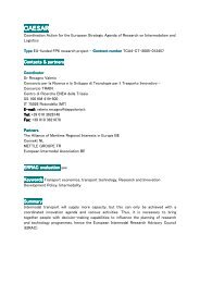
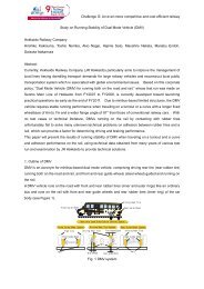
The <strong>Storage</strong> System<br />
A typical propulsion system will have a power supply, inverters, feeding the motors or auxiliaries and an<br />
energy storage subsystem, connected in parallel to the dc-link. The whole system will be controlled by an<br />
energy management, which is e.g. charging or discharging the energy storage.<br />
A) „Catenary“<br />
el. Supply,<br />
overhead wire<br />
B) „Fuell Cell“<br />
C) „Diesel“<br />
D)„Wireless tram“<br />
el. supply at stations<br />
figure 1: <strong>Storage</strong> system<br />
Supply<br />
Local control<br />
Fuel Cell<br />
Local control<br />
Diesel Engine,<br />
Generator, Rectifier<br />
energy transfer<br />
at stations<br />
<strong>Energy</strong> Management/Control<br />
a) SuperCap<br />
b) Flywheel<br />
<strong>Energy</strong> <strong>Storage</strong><br />
Local control<br />
dc/dc<br />
conv.<br />
Local control<br />
3-phase<br />
inverter<br />
Flywheel<br />
Inverter<br />
• traction motor<br />
• auxiliaries<br />
load
Different systems could per<strong>for</strong>m the function “power supply”, see figure 1: A) an electrical catenary, B) a Fuel<br />
Cell subsystem, C) a diesel engine with generator and rectifier or D) an electrical supply only connected in a<br />
station (as described e.g. in [2]).<br />
The energy storage subsystem, could be realised in two ways, a) with SuperCaps controlled by a chopper or<br />
with b) flywheels controlled by an 3-phase inverter.<br />
Best Suitable Applications<br />
The main idea behind energy storage applications is to reuse the braking energy. <strong>Railway</strong> applications <strong>for</strong><br />
electrified main lines could feed back the braking energy into the electrical network but some applications like<br />
DMUs (Diesel Multiple Units) are lacking this energy feedback possibility. There<strong>for</strong>e DMUs are a good<br />
candidate <strong>for</strong> energy storage, even in future when the diesel power pack might be replaced by on board Fuel<br />
Cell power supplies.<br />
Applications with limited feed back possibilities are e.g. trams. Modern trams are able to feed back braking<br />
energy to the overhead wire, but most of the substations are not able to feed back the energy to the energy<br />
distribution networks (e.g. when the conversion from AC to DC is realised by diode bridges) and due to very<br />
short acceleration times of other vehicles it is seldom possible to feed back the braking energy to another<br />
vehicle which is in the starting phase. The experience is, that only about 25% of the braking energy could be<br />
reused in a tram network, the rest is wasted in the on board braking resistors.<br />
Applications with short distance between stops is another important factor, leading to an optimum of installed<br />
energy storage components against stored energy, because the braking energy could be stored and reused more<br />
often than in other applications.<br />
The absolute value of the braking energy is less important since weight and costs <strong>for</strong> the energy storage are<br />
more or less proportional to the absolute storage amount of the energy storage. There<strong>for</strong>e high speed trains, as<br />
well as vehicles with good regeneration per<strong>for</strong>mance as regional and suburban EMUs (Electrical Multiple<br />
Units) are not belonging to the preferred applications [1].<br />
Supply <strong>Systems</strong> best suited aplication Why<br />
Catenary<br />
(Electrical Overhead Wire)<br />
Diesel Engine<br />
Fuell Cell<br />
"Wireless trams"<br />
<strong>Energy</strong> Supply at stations<br />
Tram or<br />
Suburban Commuter<br />
Regional Train<br />
Diesel Electric System<br />
Tram or<br />
Regional Train<br />
Tram<br />
Light Rail Vehicle<br />
Table 1: Preferred applications <strong>for</strong> energy storage<br />
<strong>Energy</strong> <strong>Storage</strong> <strong>for</strong> Catenary fed Trams<br />
<strong>Storage</strong> of braking energy<br />
- Very short distance between stops<br />
- Limited energy feedback possibility<br />
<strong>Storage</strong> of braking energy<br />
- Medium distance between stops<br />
- No energy feedback possible<br />
- Very high energy costs (up to 1Euro/liter)<br />
<strong>Storage</strong> of braking energy<br />
- Very high costs of Fuel Cells<br />
(stored breaking energy reduces power of FC)<br />
- No energy feedback possible<br />
<strong>Storage</strong> of energy<br />
- Image of cities ("wireless")<br />
- No energy supply on tracks possible ?<br />
The main goal of the energy storage is to reuse the braking energy, at least the part which could not be fed back<br />
in the catenary (typically only 25% of the braking energy could be fed back into the catenary).<br />
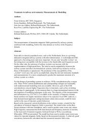
During braking mode the energy storage will be charged. During driving mode of the tram, the energy storage<br />
has to be discharged. Furthermore this reduces the power taken from the overhead wire. The energy<br />
management <strong>for</strong> discharging the energy storage has some degree of freedom, in the shown example in figure 2,<br />
it is an optimisation by taking several factors into account, e.g. losses in the overhead wire, losses in the energy<br />
storage and peak power from the line.<br />
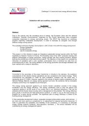
In figure 2 a typical driving cycle of a tram is selected. The traction power Ptract(t) is given by the requested<br />
runtime per<strong>for</strong>mance of the vehicle. In the first 13 seconds, when the vehicle is accelerated, only about 50% of<br />
the power is coming from the line Pline(t), while the remaining 50% of the power is coming from the energy<br />
storage P-SC(t) (here SuperCaps were chosen). This is discharging the energy storage as could be seen in the<br />
energy of the SuperCaps E-SC(t). Additionally the current I-SC(t) and the voltage U-SC(t) of the SuperCaps of<br />
one drive system are shown. Depending on the total power and length of a tram, 4 or 6 drive systems are<br />
necessary <strong>for</strong> a tram, here an example with 4 drive systems were chosen. Please note that at the end of the<br />
acceleration phase (10...12 sec), when the voltage U-SC(t) of the SuperCaps is low, the power P-SC(t) from the<br />
SuperCaps is reduced to limit the current I-SC(t). This reduces the losses in the SuperCaps (Pv~R*I 2 ) as well as<br />
the current in the chopper. During braking the SuperCaps are charged again. Due to the current limit in the
eginning of the braking the line should take quite some power, if the line is not receptive enough, some power<br />
will be still wasted in the braking resistors. At the end of the cycle the energy storage is charged again.<br />
Ptract [kW] P-SC [kW]<br />
Pline [kW]<br />
E-SC [kWh]<br />
500 Ptract<br />
0<br />
-500<br />
500<br />
0<br />
-500<br />
1<br />
0.5<br />
P-SC<br />
0 10 20 30 40 50 60<br />
0 10 20 30 40 50 60<br />
0<br />
0 10 20 30<br />
time [sec]<br />
40 50 60<br />
I-SC-drive [A]<br />
U-SC [V]<br />
E-SC-drive [kWh]<br />
500<br />
0<br />
drive ~ 25% of tram)<br />
Imax-limit<br />
-500<br />
0 10 20 30 40 50 60<br />
400<br />
200<br />
0<br />
0 10 20 30 40 50 60<br />
0.3<br />
0.2<br />
0.1<br />
drive ~ 25% of tram)<br />
0<br />
0 10 20 30<br />
time [sec]<br />
40 50 60<br />
Figure 2: Operation principle of the energy storage, left side: on tram level, right side: one drive which is<br />
e.g. 25% of a tram (file typ5.m)<br />
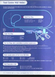
The energy storage should be designed <strong>for</strong> the right balance between saved energy and costs <strong>for</strong> the energy<br />
storage. To derive the right amount of energy storage, the driving cycle has to be taken into account. The<br />
braking energy is e.g. limited inside the city centre, because of the limited speed of the vehicle, as could be seen<br />
on left side of figure 3 (between 0 and 250sec). With a storage capacity limited to Emax of e.g. 1kWh the<br />
braking energy could be stored in most of the cases, but not in all cases, see bottom-left graph. The total saved<br />
energy over a drive cycle could be given in function of the maximum storage energy Emax. The limit is e.g. at<br />
1.6kWh, there is no braking interval with a braking energy of more than 1.6kWh, to increase the energy<br />
storage capacity above this value makes no sense. Assuming that the costs <strong>for</strong> energy storage are linear to the<br />
storage capacity combined with an offset <strong>for</strong> e.g. control costs, the optimum energy storage capacity could be<br />
found by dividing the saved energy by the costs. The optimum between invested costs and saved energy is<br />
there<strong>for</strong>e at medium braking energies of e.g. 1kWh. That means that the energy storage is not big enough to<br />
take the whole braking energy at all cases, specially at high speeds outside the city centre some energy will still<br />
be wasted in the braking resistors.<br />
P-traction, P-SC [kW]<br />
800<br />
600<br />
400<br />
200<br />
0<br />
-200<br />
-400<br />
-600<br />
-800<br />
-1000<br />
P-SC<br />
P-traction<br />
-1200<br />
0 100 200 300 400 500 600 700<br />
time [sec]<br />
E-brake, E-SC [kWh]<br />
0<br />
-0.2<br />
-0.4<br />
-0.6<br />
-0.8<br />
-1<br />
-1.2<br />
-1.4<br />
-1.6<br />
-1.8<br />
Emax<br />
-2<br />
0 100 200 300 400 500 600 700<br />
time [sec]<br />
costs & costs/Estored [%]<br />
E stored [kWh]<br />
15<br />
10<br />
5<br />
0<br />
0 0.5 1 1.5<br />
E max [kWh]<br />
2 2.5<br />
110<br />
100<br />
90<br />
80<br />
70<br />
60<br />
50<br />
40<br />
30<br />
20<br />
10<br />
cost/Estored<br />
costs<br />
0<br />
0 0.5 1 1.5<br />
E max [kWh]<br />
2 2.5<br />
Figure 3: Deriving the cost optimum amount of energy storage (file all1.m, all2,m)
A side effect is the reduction of the peak power drawn from the line. In the example the peak power is reduced<br />
to 60 ... 70%. This has a significant effect on the losses in the overhead wire. In our example the RMS value of<br />
the line current was reduced to 55 ... 65%. The ohmic losses of the line are linear to the squared RMS current<br />
which gives a reduction of the line losses to 30 ... 40%.<br />
without SCap with SCap<br />
<strong>Energy</strong> consumption 100% 65 ... 75%<br />
Line current I line-RMS 100% 55 ... 65%<br />
Losses in the line Pv=R*I*I 100% 30 ... 40%<br />
The Return Of Investment (ROI) is dependent on several factors, e.g. energy costs, material costs, saved energy<br />
– which is a function of the track, depending on factors like stopping distances and if it is in a hilly area or not.<br />
To give an idea about the ROI an example was calculated, based on predicted SuperCap costs of 2004 the ROI<br />
was between 5 and 12 years, depending on the energy costs of the operator.<br />
<strong>Energy</strong> <strong>Storage</strong> <strong>for</strong> DMUs (Diesel Multiple Units)<br />
There are 2 main applications <strong>for</strong> DMUs with energy storage seen:<br />
1. 2 car DMU with one diesel engine and energy storage<br />
2. 4 car DMU with two diesel engines and energy storage (3 car base version upgraded with energy storage)<br />
A<br />
Motor bogie Diesel engine 588 kW<br />
Figure 4: 2-car DMU with energy storage<br />
Running bogie <strong>Energy</strong> storage Motor bogie<br />
The 2 car DMU with energy storage is derived from a 2 car base version having 2 diesel engines. The costs <strong>for</strong><br />
the energy storage are partly compensated by avoiding the 2 nd diesel engine, generator and rectifier. Failures of<br />
subsystems have different effects on the availability of the vehicle. A total failure of the energy storage will lead<br />
to reduced power of one diesel engine, while a failure of a diesel engine will lead to a stopping failure after a<br />
while, when the energy storage is empty.<br />
The 4 car DMU is based on a standard 3 car version with the same propulsion system but with an additional<br />
energy storage to compensate <strong>for</strong> the higher mass of the vehicle and achieve same travel times. All failures in<br />
subsystems will not cause a stopping failure unless several failures appear at the same time.<br />
A typical driving cycle is shown in figure 5. The principle is similar to the one already explained <strong>for</strong> a tram,<br />
there<strong>for</strong>e only some different features are explained here. The main difference is given by longer time scales<br />
and by a different control of the energy storage. The power P-SC(t) of the energy storage is controlled in a way<br />
that the power P-dsl(t) taken from the diesel is limited. This reduces the necessary amount of installed diesel<br />
power.<br />
Ptract [kW] P-SC [kW]<br />
P-dsl [kW]<br />
1000<br />
0<br />
P-SC<br />
-1000<br />
0 50 100 150 200 250 300<br />
1000<br />
E-SC [kWh]<br />
500<br />
0<br />
0 50 100 150 200 250 300<br />
10<br />
5<br />
0<br />
0 50 100 150 200 250 300<br />
P-SC [kW] I-SC [A]<br />
2000 I-SC<br />
0<br />
-2000<br />
Imax-limit<br />
0 50 100 150 200 250 300<br />
800<br />
U-SC [V]<br />
E-SC [kWh]<br />
600<br />
400<br />
200<br />
0<br />
0 50 100 150 200 250 300<br />
10<br />
5<br />
0<br />
0 50 100 150 200 250 300<br />
Figure 5: Operation principle of the energy storage <strong>for</strong> a DMU (file Estyp20.m)<br />
Next to the possible reduction of the installed diesel engine power the energy storage on a DMU could be used<br />
<strong>for</strong> other features:
• noise reduction in stations – when the auxiliaries are fed by the energy storage and the diesel angine is<br />
switched off,. Of course this discharges the energy storage and only the remaining energy could be used<br />
<strong>for</strong> the next acceleration phase.<br />
• emission reduction in tunnels – the diesel engine might be switched off<br />
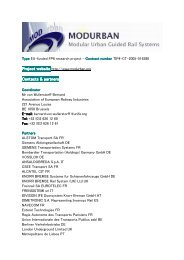
Calculations on energy and costs savings depend on several boundary conditions, as installed energy storage<br />
capacity, energy management and of course the track data itself (distance between stops, flat or hilly area,<br />
gradient of hills). Nevertheless an indication on the saved energy and fuel <strong>for</strong> a 2car DMU could be given in<br />
figure 6, the boundary values marked in blue are given by -1% slope downhill and +1% slope uphill. The<br />
energy storage was chosen to 9kWh <strong>for</strong> applications up to 8km average stopping distance and to 12kWh<strong>for</strong> up<br />
to 14km stopping distance.<br />
The ROI (Return of Investment) is dependent on even more influence factors like fuel price, investment cost,<br />
cost <strong>for</strong> energy storage, saved maintenance costs and others. To give an idea on the ROI, a special case with<br />
200'000 km/year and SuperCap costs in 2004 was chosen and the ROI was calculated in function of the fuel<br />
price. The saved maintenance costs on brakes and on one instead of two diesel engine systems was taken into<br />
account. In order to give an idea on the influence of the stopping distance, 2 curves with 30% and 40% saved<br />
energy are plotted. Only the saved fuel was taken into account, but not emission reductions.<br />
saved <strong>Energy</strong> or Fuel [%]<br />
50<br />
45<br />
40<br />
35<br />
30<br />
25<br />
20<br />
15<br />
10<br />
5<br />
0<br />
4 5 6 7 8 9 10 11 12 13 14<br />
average distance between stops [km]<br />
max<br />
typical<br />
min<br />
ROI [years]<br />
10<br />
8<br />
6<br />
4<br />
2<br />
SuperCap costs 2004<br />
5% interest saved<br />
<strong>Energy</strong><br />
0<br />
0.2 0.4 0.6 0.8 1 1.2 1.4<br />
5<br />
4<br />
3<br />
2<br />
1<br />
low per<strong>for</strong>mance train<br />
high per<strong>for</strong>mance train<br />
0<br />
0.2 0.4 0.6 0.8 1 1.2 1.4<br />
price of diesel [Euro/liter]<br />
Figure 6: Saved energy in function of the stopping distance and ROI calculation principle (file length3.m<br />
ROI2i.m)<br />
In the calculation of the Return of Investment in figure 6 the emission reduction was not taken into account,<br />
because it is very difficult to turn it into a cost value, furthermore this would be totally different from country to<br />
country. Possible investment savings on the diesel power pack were not taken into account, because they are<br />
dependent on the systems to be compared, whether it is compared to a diesel-mechanic system or dieselhydraulic<br />
system.<br />
Please note that the ROI is based on estimated material costs in 2004, the predicted cost decrease on energy<br />
storage components will lead to further improvements.<br />
<strong>Energy</strong> <strong>Storage</strong> technologies<br />
In the railway application field some energy storage technologies are competing, e.g. batteries, flywheels and<br />
SuperCaps. The best choice could be derived from the application dependent requirements. In this paper the<br />
following railway application were found as best suited:<br />
• Tram fed by el. catenary: “power type energy storage”<br />
e.g. E=1kWh, P=600kW, T=E/P= 6sec, 6 Mio load cycles<br />
• 2-car Diesel Multiple Unit: “energy type energy storage”<br />
e.g. E=9kWh, P=900kW, T=E/P= 36sec, 2 Mio load cycles<br />
• 4-car Diesel Multiple Unit: “energy type energy storage”<br />
e.g. E=9kWh, P=300kW, T=E/P=108sec, 2 Mio load cycles<br />
That means, that the demands on the energy storage <strong>for</strong> a tram application is more from the power type while<br />
the demands from the DMUs are more from the energy type. The question “Which energy storage technology<br />
fulfils all requirements to the lowest costs” is still open.<br />
In case of a tram application SuperCaps seem to be the best choice, due to the high power demand, the freedom<br />
in dimensions and safety aspects <strong>for</strong> low floor vehicles, where the storage device has to be placed on the roof.<br />
ROI [years]<br />
20%<br />
40%<br />
saved<br />
<strong>Energy</strong><br />
20%<br />
40%
In case of the regional diesel train the question, if the SuperCap or the Flywheel will be the best choice, seems<br />
to be open. When the fast improvement of SuperCaps is going on, the best from technical and economical point<br />
of view might be to realise all applications with the same energy storage technology, the SuperCaps.<br />
The requirements on cycling capability and availability could not be fully proven up to now, but it seems to be<br />
solvable problems, when putting the necessary attention and resources on this topics.<br />
To realise the energy storage, SuperCaps have to be mounted in modules, connected in series and in parallel.<br />
The number of series connected SuperCaps is depending on the application, typical ranges might be from 160<br />
to 320 in series. Symmetrysing circuits have to be used, when the de-rating on the cell voltage should be<br />
neglectable low.<br />
To share the development costs of SuperCap modules within several applications, e.g. automobile and railway,<br />
the complete energy storage module should be delivered from the SuperCap manufacturer. Which means he has<br />
to take over the responsibility <strong>for</strong> availability, redundancy, cycling capability, vibration tested mounting and a<br />
part of the cooling. The overall responsibility and the application dependent subsystems like<br />
charging/discharging chopper but also the energy management has to be delivered from the vehicle<br />
manufacturer.<br />
The share of vehicles with energy storage is mainly depending on their ROI (Return Of Investment). <strong>Energy</strong><br />
storage needs additional investment costs, with the main part on the storage modules, which will payback by<br />
the saved energy costs. To achieve interesting ROI times less than 5 years the decrease on costs <strong>for</strong> storage<br />
components has to go on.<br />
On the other side vehicle operators should be aware that they have to invest first, be<strong>for</strong>e they get paid back by<br />
saved energy costs.<br />
Lab System<br />
The theoretical results are completed by practical experience from lab systems. A lab system with SuperCaps<br />
has been build up to get experience with the storage system, the control, the losses, the load cycling. The main<br />
focus of the lab test is to get a clear design rule <strong>for</strong> a reliable SuperCap storage system, designed <strong>for</strong> the whole<br />
lifetime of a tram. SuperCap modules <strong>for</strong> a tram are shown in figure 7. They consist on single SuperCaps<br />
mounted in series and in parallel. On their top, active symetrising circuits are placed. In figure 7 four boxes<br />
could be seen, which are enough <strong>for</strong> one out of e.g. four drive systems of a complete tram.<br />
Figure 7: Photo from SuperCap modules, with symmetrysing circuits on top<br />
Conclusion<br />
It was shown that on board energy storage will become an application field <strong>for</strong> light rail vehicles (trams) as<br />
well as <strong>for</strong> Diesel Multiple Units, at least when the prediction of costs <strong>for</strong> energy storage will be realised.<br />
The application dependent benefits <strong>for</strong> the operator are:<br />
• in general:<br />
• reduction of emissions<br />
• “green image”<br />
• <strong>for</strong> Tram application (with catenary, overhead wire):<br />
• Decreased energy consumption, decreased energy costs
• Lower average power demand from substations,<br />
more vehicles on existing lines possible<br />
no power limits from substations on the vehicle per<strong>for</strong>mance<br />
• Lower peak and RMS power of vehicles (lower losses in catenary and in substations)<br />
• <strong>for</strong> Diesel Multiple Units:<br />
• Decreased energy consumption, decreased energy costs<br />
• Additional power from the energy storage, leading to reduced peak power of diesel engines, reduction<br />
of installed diesel power (e.g. 1 instead of 2 diesel engines)<br />
• Longer trains by adding an additional car with energy storage<br />
<strong>Energy</strong> storage results in increased investment costs <strong>for</strong> the additional feature. Vehicle operators should be<br />
aware that they have to invest first be<strong>for</strong>e they get paid back by saved energy costs.<br />
<strong>Energy</strong> storage on board of railway vehicles is still in a prototype state. Some open technical and commercial<br />
tasks have to be solved, but they seem to be uncritical. Nevertheless applications will not be done without any<br />
risk share between operator and vehicle manufacturer. There<strong>for</strong>e it is to early to introduce energy storage in a<br />
bigger portion of new vehicles, but at least new vehicles should be prepared <strong>for</strong> the future. That means that<br />
vehicles <strong>for</strong> intensive usage - with a high energy saving potential - should be equipped with electrical traction<br />
equipment (here Diesel Electric should be preferred instead of Diesel Hydraulic or Diesel Mechaniuc).<br />
References<br />
[1] F. Hentschel, K. Mueller, M. Steiner, “<strong>Energy</strong> <strong>Storage</strong> on Urban <strong>Railway</strong> Vehicles”,<br />
UIC <strong>Railway</strong> <strong>Efficiency</strong> Conference May 2000<br />
[2] G. Pereira, P Bartholomeus, P. Le Moigne, C. Rombaut, P. van Berten: “Ultracapacitors and tramway<br />
without catenary”, 2 nd BOOSTCAP Meeting 2001, Fribourg (CH)<br />
[3] M. Steiner, R. Manser: “<strong>Energy</strong> <strong>Storage</strong> in <strong>Railway</strong> applications ”, 2 nd BOOSTCAP Meeting 2001,<br />
Fribourg (CH)<br />
[4] P. Barrade, S. Pittet, A. Rufer: “<strong>Energy</strong> storage System using a series connection of supercapacitors,<br />
with an active device <strong>for</strong> equalising the voltages“, IPEC 2000, Tokyo