surface-mount broadband balun bal-0006sm - Marki Microwave
surface-mount broadband balun bal-0006sm - Marki Microwave
surface-mount broadband balun bal-0006sm - Marki Microwave

You also want an ePaper? Increase the reach of your titles
YUMPU automatically turns print PDFs into web optimized ePapers that Google loves.
D/C<br />
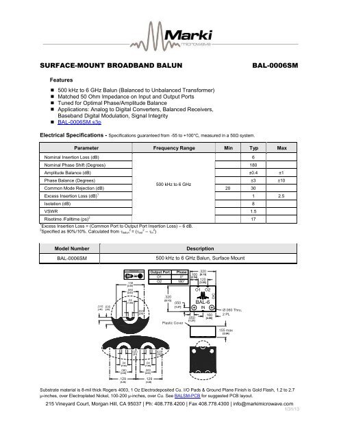
SURFACE-MOUNT BROADBAND BALUN<br />
BAL-0006SM<br />
Features<br />
500 kHz to 6 GHz Balun (Balanced to Un<strong>bal</strong>anced Transformer)<br />
Matched 50 Ohm Impedance on Input and Output Ports<br />
Tuned for Optimal Phase/Amplitude Balance<br />
Applications: Analog to Digital Converters, Balanced Receivers,<br />
Baseband Digital Modulation, Signal Integrity<br />
BAL-0006SM.s3p<br />
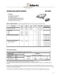
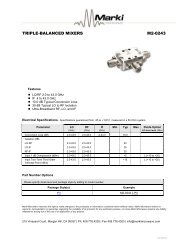
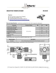
Electrical Specifications - Specifications guaranteed from -55 to +100°C, measured in a 50Ω system.<br />
Nominal Insertion Loss (dB)<br />
Parameter Frequency Range Min Typ Max<br />
Nominal Phase Shift (Degrees) 180<br />
Amplitude Balance (dB) ±0.4 ±1<br />
Phase Balance (Degrees) ±3 ±10<br />
500 kHz to 6 GHz<br />
Common Mode Rejection (dB) 20 30<br />
Excess Insertion Loss (dB) 1 1 2.5<br />
Isolation (dB) 8<br />
VSWR 1.5<br />
Risetime /Falltime (ps) 2 17<br />
1 Excess Insertion Loss = (Common Port to Output Port Insertion Loss) – 6 dB.<br />
2 Specified as 90%/10%. Calculated from <strong><strong>bal</strong>un</strong> 2 = ( out 2 – in 2 )<br />
6<br />
Model Number<br />
BAL-0006SM<br />
Description<br />
500 kHz to 6 GHz Balun, Surface Mount<br />
.015 .035<br />
[.41] [.91]<br />
PROJECTION<br />
.138<br />
[3.50]<br />
.080<br />
[2.03]<br />
.04<br />
[1.02]<br />
INCH<br />
[MM]<br />
.020<br />
[.51]<br />
Output Port<br />
O1<br />
O2<br />
.320<br />
[8.13]<br />
Phase<br />
0°<br />
180°<br />
.050<br />
[1.27]<br />
Plastic Cover<br />
.100<br />
[2.54]<br />
.050<br />
[1.27]<br />
O1<br />
.320<br />
[8.13]<br />
.120<br />
[3.05]<br />
O2<br />
BAL-6<br />
IN<br />
.160<br />
[4.06]<br />
Ø.060 Thru,<br />
2 PL<br />
.155 max<br />
[3.94]<br />
.020<br />
[.51]<br />
.020<br />
[.51]<br />
.04<br />
[1.02]<br />
.080<br />
[2.03]<br />
.129<br />
[3.28]<br />
.04<br />
[1.02]<br />
.080<br />
[2.03]<br />
.129<br />
[3.28]<br />
Substrate material is 8-mil thick Rogers 4003, 1 Oz Electrodeposited Cu. I/O Pads & Ground Plane Finish is Gold Flash, 1.2 to 2.7<br />
µ-inches, over Electroplated Nickel, 100-200 µ-inches, over Cu. See BALSM-PCB for suggested PCB layout.<br />
215 Vineyard Court, Morgan Hill, CA 95037 | Ph: 408.778.4200 | Fax 408.778.4300 | info@markimicrowave.com<br />
1/31/13
Amplitude Balance (dB)<br />
Insertion Loss\ Isolation (dB)<br />
Phase Balance (degree)<br />
Return Loss (dB)<br />
SURFACE-MOUNT BROADBAND BALUN<br />
BAL-0006SM<br />
Page 2<br />
Block Diagram<br />
180°<br />
0°<br />
180°<br />
0°<br />
Single ended to differential<br />
Differential to single ended<br />
Typical Performance<br />
0<br />
-2<br />
-4<br />
Insertion Loss (Output 1)<br />
Insertion Loss (Output 2)<br />
Isolation<br />
0<br />
-5<br />
Common<br />
Output 1<br />
Output 2<br />
-6<br />
-10<br />
-8<br />
-10<br />
-12<br />
-14<br />
0 1 2 3 4 5 6<br />
Frequency (GHz)<br />
-15<br />
-20<br />
-25<br />
0 1 2 3 4 5 6<br />
Frequency (GHz)<br />
Fig. 1. Common to output port insertion loss and output to<br />
output port Isolation.<br />
Fig. 2. Return loss for common port and output ports.<br />
2<br />
1.5<br />
1<br />
0.5<br />
0<br />
-0.5<br />
-1<br />
-1.5<br />
-2<br />
0 1 2 3 4 5 6<br />
Frequency (GHz)<br />
200<br />
195<br />
190<br />
185<br />
180<br />
175<br />
170<br />
165<br />
160<br />
0 1 2 3 4 5 6<br />
Frequency (GHz)<br />
Fig. 3. Amplitude <strong>bal</strong>ance between output ports.<br />
Fig. 4. Phase <strong>bal</strong>ance between output ports.<br />
215 Vineyard Court, Morgan Hill, CA 95037 | Ph: 408.778.4200 | Fax 408.778.4300 | info@markimicrowave.com<br />
1/31/13
Common Mode Rejection (dB)<br />
SURFACE-MOUNT BROADBAND BALUN<br />
BAL-0006SM<br />
Page 3<br />
0<br />
-10<br />
-20<br />
-30<br />
-40<br />
-50<br />
0 1 2 3 4 5 6<br />
Frequency (GHz)<br />
Fig. 5. Common mode rejection.<br />
INPUT PATTERN OUTPUT DATA OUTPUT INVERTED DATA<br />
INPUT EYE<br />
OUTPUT DATA<br />
OUTPUT INVERTED DATA<br />
Fig. 6. Oscilloscope measurements of the BAL-0006SM with a 6 Gb/s PRBS pattern. Bit pattern is measured<br />
with a 2 7 -1 PRBS input demonstrating extremely good pulse fidelity for both inverted and non-inverted output.<br />
Eye diagrams are taken with a 2 31 -1 PRBS input demonstrating minimal eye distortion/closure afforded by the<br />
extremely low frequency operation of the <strong><strong>bal</strong>un</strong> (