4/3, 4/2 and 3/2-way directional valves with wet pin ... - Bosch Rexroth
4/3, 4/2 and 3/2-way directional valves with wet pin ... - Bosch Rexroth
4/3, 4/2 and 3/2-way directional valves with wet pin ... - Bosch Rexroth

You also want an ePaper? Increase the reach of your titles
YUMPU automatically turns print PDFs into web optimized ePapers that Google loves.
Electric Drives<br />
<strong>and</strong> Controls<br />
Hydraulics<br />
Linear Motion <strong>and</strong><br />
Assembly Technologies Pneumatics Service<br />
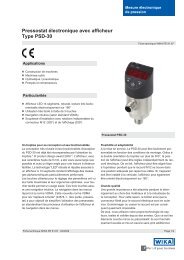
4/3, 4/2 <strong>and</strong> 3/2-<strong>way</strong><br />
<strong>directional</strong> <strong>valves</strong> <strong>with</strong> <strong>wet</strong> <strong>pin</strong><br />
DC or AC solenoids<br />
RA 23327/04.04 1/12<br />
Replaces<br />
RA 23 316/06.98<br />
Model WE 10 ../.C<br />
Nominal size 10<br />
Series 3X (individual connections)<br />
Series 4X (central connections)<br />
Maximum operating pressure 315 bar (4600 PSI)<br />
Maximum flow 120 L/min (32 GPM)<br />
List of contents<br />
Contents<br />
Page<br />
Features 1<br />
Ordering details 2<br />
Symbols 3<br />
St<strong>and</strong>ard types 3<br />
Function, section 4<br />
Technical data 5<br />
Characteristic curves 6<br />
Performance limits 6, 7<br />
Unit dimensions 8–11<br />
Plug-in connectors 12<br />
Features<br />
– Direct solenoid operated <strong>directional</strong> spool valve,<br />
st<strong>and</strong>ard version<br />
– Porting pattern to DIN 24 340 form A,<br />
ISO 4401 <strong>and</strong> CETOP–RP 121 H; NFPA T3.5.1 MR1 <strong>and</strong><br />
ANSI B93.7 D05<br />
subplates to catalog sheet RE 45 054<br />
(separate order)<br />
– Wet <strong>pin</strong> AC or DC solenoids <strong>with</strong> removable coil<br />
– Solenoid coil can be rotated through 90°<br />
– Coils may be replaced <strong>with</strong>out opening the pressure<br />
tight chamber<br />
– Electrical connections available as either individual<br />
connections or as a central connection<br />
– H<strong>and</strong> override, optional<br />
– For soft switching version, see RE 23 183<br />
– For inductive limit switch (contact <strong>and</strong> proximity),<br />
see RE 24 830
2/12 <strong>Bosch</strong> <strong>Rexroth</strong> Corp. | Industrial Hydraulics WE 10 ../.C | RA 23327/02.03<br />
Ordering details<br />
3 actuator ports<br />
4 actuator ports<br />
= 3<br />
= 4<br />
Nominal size 10 = 10<br />
Symbol e.g. C, E, EA, EB etc. – for possible versions see page 3<br />
Series 30 to 39 – individual connection<br />
(30 to 39: unchanged installation <strong>and</strong> connection dimensions)<br />
Series 40 to 49 – central connection<br />
(40 to 49: unchanged installation <strong>and</strong> connection dimensions)<br />
With spring return<br />
Without spring return, <strong>with</strong> detent<br />
Without spring return<br />
Wet <strong>pin</strong> solenoid (oil immersed) <strong>with</strong> removable coil<br />
24 V DC<br />
230 V AC 50/60 Hz<br />
205 V DC<br />
Ordering details for other voltages <strong>and</strong> frequencies see page 5.<br />
With protected h<strong>and</strong> override (st<strong>and</strong>ard)<br />
Without h<strong>and</strong> override<br />
H<strong>and</strong> override <strong>with</strong> protective cap<br />
= 3X<br />
= 4X<br />
= No code<br />
= OF<br />
= O<br />
Types of electrical connections<br />
1/2” NPT conduit connector in conduit box<br />
1/2” NPT conduit connector in conduit box <strong>with</strong> light(s)<br />
ANSI B 93.55 M plug-in type connections (<strong>with</strong>out female end)<br />
Terminal box <strong>with</strong> 3-<strong>pin</strong> connector (single solenoid)<br />
Terminal box <strong>with</strong> 5-<strong>pin</strong> connector (double solenoid)<br />
Terminal box <strong>with</strong> 3-<strong>pin</strong> connector <strong>and</strong> lights (single solenoid)<br />
Terminal box <strong>with</strong> 5-<strong>pin</strong> conenctor <strong>and</strong> lights (double solenoid)<br />
Individual solenoid plug connections for cable or conduit (1/2” NPT)<br />
Without plug-in connector(s)<br />
Accessories<br />
With inductive limit switch (for ordering details see catalogue sheet RE 24 830)<br />
Without limit switch<br />
Without cartridge throttle<br />
Throttle Ø 0.8 mm (0.031 in.)<br />
Throttle Ø 1.0 mm (0.039 in.)<br />
Throttle Ø 1.2 mm (0.047 in.)<br />
NBR seals<br />
FKM seals<br />
(other seals on request)<br />
Further details in clear text<br />
WE 10 / C / *<br />
Used where the fl ow > than the<br />
perforamce limit of the <strong>valves</strong><br />
effective in P port<br />
= C<br />
= G24<br />
= W230<br />
= G205 1)<br />
= N9<br />
= No code<br />
= N<br />
= DA<br />
= DAL<br />
= DK23<br />
= DK25<br />
= DK23L<br />
= DK25L<br />
= K4 2)<br />
= No code<br />
= No code<br />
= B08<br />
= B10<br />
= B12<br />
= No code<br />
= V<br />
Attention! The compatibility of the seals <strong>and</strong> pressure fl uid has to be taken into account!<br />
1)<br />
When connecting to an AC supply a DC solenoid must<br />
be used which is controlled via a rectifi er (see table below).<br />
With an individual connection a large plug-in connector <strong>with</strong><br />
built-in rectifi er can be used<br />
(separate order, see page 3).<br />
DC solenoids used <strong>with</strong> an AC supply<br />
2)<br />
Plug-in connectors must be ordered separately<br />
(see page 3).<br />
3)<br />
Plug-in connector (Material No. R900005538) must be<br />
ordered separately.<br />
AC solenoids may be used for several types of supplies:<br />
AC supply<br />
(permissible voltage<br />
tolerance ± 10%)<br />
Nominal voltage of the<br />
DC solenoid when used <strong>with</strong><br />
an AC supply via rectifi er<br />
Order<br />
detail<br />
110 V – 50/60 Hz 120 V – 60 Hz G96<br />
96 V 110 V G110<br />
230 V – 50/60 Hz 205 V G205<br />
Supply<br />
42 V, 50 Hz<br />
42 V, 60 Hz<br />
110 V, 50 HZ<br />
110 V, 60 Hz<br />
120 V, 60 Hz<br />
230 V, 50 Hz<br />
230 V, 60 Hz<br />
Ordering details<br />
W42<br />
W110<br />
W230
RA 23327/02.03 | WE 10 ../.C Industrial Hydraulics | <strong>Bosch</strong> <strong>Rexroth</strong> Corp. 3/12<br />
Symbols<br />
a<br />
A B<br />
b<br />
P T<br />
a<br />
a<br />
A B<br />
a b<br />
b<br />
P T<br />
A B<br />
a b b …/O..<br />
P T<br />
A B<br />
a 0<br />
P T<br />
A B<br />
a 0<br />
P T<br />
b<br />
a<br />
a<br />
A B<br />
a 0<br />
P T<br />
A B<br />
a 0<br />
P T<br />
b<br />
b<br />
= .A 1)<br />
1)<br />
Example:<br />
Spool E <strong>with</strong> switched position “a”<br />
Ordering detail..EA..<br />
a<br />
a b b …/OF..<br />
A B<br />
0<br />
b<br />
A B<br />
0 b<br />
b<br />
= .B<br />
P<br />
T<br />
P<br />
T<br />
= A<br />
= E 1)<br />
= P<br />
= C<br />
= F<br />
= Q<br />
= D<br />
= G<br />
= R<br />
A B<br />
a<br />
P T<br />
b<br />
a<br />
A B<br />
a<br />
P T<br />
b<br />
b<br />
= H<br />
= T<br />
= B<br />
= J<br />
= U<br />
= Y<br />
= L<br />
= V<br />
= M<br />
= W<br />
St<strong>and</strong>ard types<br />
Type Material number<br />
3WE 10 A3X/CG24N9K4<br />
R900592014<br />
3WE 10 A3X/CW230N9K4<br />
R900915675<br />
3WE 10 B3X/CG24N9K4<br />
R900594429<br />
3WE 10 B3X/CW230N9K4<br />
R900517341<br />
4WE 10 C3X/CG24N9K4<br />
R900593277<br />
4WE 10 C3X/CW230N9K4<br />
R900915651<br />
4WE 10 D3X/CG24N9K4<br />
R900589933<br />
4WE 10 D3X/CW230N9K4<br />
R900912496<br />
4WE 10 E3X/CG24N9K4<br />
R900588201<br />
4WE 10 E3X/CW230N9K4<br />
R900911869<br />
4WE 10 F3X/CG24N9K4<br />
R900529749<br />
4WE 10 F3X/CW230N9K4<br />
R900918361<br />
4WE 10 G3X/CG24N9K4<br />
R900594277<br />
4WE 10 G3X/CW230N9K4<br />
R900912497<br />
4WE 10 H3X/CG24N9K4<br />
R900597986<br />
4WE 10 H3X/CW230N9K4<br />
R900503425<br />
4WE 10 J3X/CG24N9K4<br />
R900589988<br />
4WE 10 J3X/CW230N9K4<br />
R900911868<br />
4WE 10 L3X/CG24N9K4<br />
R900599646<br />
4WE 10 L3X/CW230N9K4<br />
R900915669<br />
Type<br />
4WE 10 M3X/CG24N9K4<br />
4WE 10 M3X/CW230N9K4<br />
4WE 10 P3X/CG24N9K4<br />
4WE 10 Q3X/CG24N9K4<br />
4WE 10 Q3X/CW230N9K4<br />
4WE 10 R3X/CG24N9K4<br />
4WE 10 R3X/CW230N9K4<br />
4WE 10 T3X/CG24N9K4<br />
4WE 10 T3X/CW230N9K4<br />
4WE 10 U3X/CG24N9K4<br />
4WE 10 U3X/CW230N9K4<br />
4WE 10 V3X/CG24N9K4<br />
4WE 10 V3X/CW230N9K4<br />
4WE 10 W3X/CG24N9K4<br />
4WE 10 W3X/CW230N9K4<br />
4WE 10 Y3X/CG24N9K4<br />
4WE 10 Y3X/CW230N9K4<br />
Material number<br />
R900500932<br />
R900916118<br />
R900500716<br />
R900591325<br />
R900921465<br />
R900598583<br />
R900593804<br />
R900503424<br />
R900931784<br />
R900592655<br />
R900909906<br />
R900921780<br />
R900919553<br />
R900588200<br />
R900521281<br />
R900595531<br />
R900915670
4/12 <strong>Bosch</strong> <strong>Rexroth</strong> Corp. | Industrial Hydraulics WE 10 ../.C | RA 23327/02.03<br />
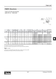
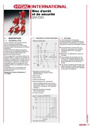
Function, section<br />
Directional <strong>valves</strong> type WE are solenoid operated <strong>directional</strong><br />
spool <strong>valves</strong>. They are used to control the start, stop <strong>and</strong> direction<br />
of a fl ow.<br />
The <strong>directional</strong> <strong>valves</strong> basically comprise of the housing (1), one<br />
or two solenoids (2), a control spool (3), <strong>and</strong> one or two return<br />
springs (4).<br />
In the de-energised condition the control spool (3) is held in its<br />
central or initial position be means of the return springs (4) (<strong>with</strong><br />
the exception of impulse spools). The control spool (3) is operated<br />
by the <strong>wet</strong> <strong>pin</strong> solenoids (2).<br />
In order to ensure correct function care must be taken that the<br />
solenoid pressure chamber is fi lled <strong>with</strong> oil.<br />
The force of solenoid (2) acts on the control spool (3) <strong>and</strong> moves<br />
it from its initial position to the desired end position. This permits<br />
free fl ow from P to A <strong>and</strong> B to T or P to B <strong>and</strong> A to T.<br />
On de-energising the solenoid (2) the control spool (3) is returned<br />
to its initial position by the return spring (4).<br />
The optional h<strong>and</strong> override (5) permits the control spool (3) to be<br />
moved <strong>with</strong>out the solenoids being energised.<br />
5 2 4 1 3 4 2 5<br />
A<br />
B<br />
“a”<br />
“b”<br />
Type 4WE 10 E3X/CG24N9K4<br />
TA<br />
A<br />
P<br />
B<br />
TB<br />
Type .WE 10.3X/OC....<br />
(only possible <strong>with</strong> symbols A, C <strong>and</strong> D)<br />
This model is a 2-position <strong>directional</strong> valve <strong>with</strong> 2 solenoids<br />
<strong>with</strong>out detents. The spool position, when the solenoids are<br />
de-energised, is not defi ned.<br />
A<br />
Type .WE 10.3X/OFC... (impulse spool), <strong>with</strong> detent<br />
(only possible <strong>with</strong> symbols A, C <strong>and</strong> D)<br />
This model is a 2-position <strong>directional</strong> valve <strong>with</strong> 2 solenoids <strong>and</strong><br />
detents. Hence, when the solenoids are de-energised, the spool<br />
is held in the detented position <strong>and</strong> thus the solenoids do not<br />
need to be continuously energised.<br />
Detent<br />
“a”<br />
Type .WE 10.3X/OFC (impulse spool)<br />
TA<br />
Cartridge throttle (type 4WE 10…/.../B..)<br />
A cartridge throttle is required when, if due to the operating conditions,<br />
fl ows can occur during the switching procedure which<br />
are higher than the permitted performance limits of the valve.<br />
The throttle is inserted into the P port of the <strong>directional</strong> valve.<br />
P
RA 23327/02.03 | WE 10 ../.C Industrial Hydraulics | <strong>Bosch</strong> <strong>Rexroth</strong> Corp. 5/12<br />
Technical data (for applications outside these parameters, please consult us!)<br />
General<br />
Installation<br />
Optional<br />
ambient temperature range °C (°F) –30 to +50 (–22 to +122) – NBR seals<br />
–20 to +50 (–4 to +122) – FKM seals<br />
Weight Central connection Individual connection<br />
Valve <strong>with</strong> 1 solenoid kg (lbs.) 4.4 (9.7) (=); 3.6 (7.9) (~) 4.3 (9.5) (=); 3.5 (7.7) (~)<br />
Valve <strong>with</strong> 2 solenoids kg (lbs.) 6.0 (13.2) (=); 4.4 (9.7) (~) 5.9 (13.0) (=); 4.3 (9.5) (~)<br />
Hydraulic<br />
Max. operating pressure Ports A, B, P bar (PSI) 315 (4600)<br />
Port T bar (PSI) 210 (3050) (=) ; 160 (2320) (~)<br />
For symbols A <strong>and</strong> B port T must be used as a drain line,<br />
if the operating pressure is higher than the permissible<br />
tank pressure.<br />
Max. fl ow L/min (GPM) 120 (32)<br />
Flow cross-section For symbol V mm 2 (in 2 ) 11 (0.017) (A/B → T); 10.3 (0.016) (P → A/B)<br />
(switched position 0) For symbol W mm 2 (in 2 ) 2.5 (0.004) (A/B → T)<br />
For symbol Q mm 2 (in 2 ) 5.5 (0.009) (A/B → T)<br />
Pressure fl uid Mineral oil (HL, HLP) to DIN 51 524 1);<br />
Fast bio-degradable pressure fl uids to<br />
VDMA 24 568 (also see RE 90 221); HETG (rape seed oil) 1) ;<br />
HEPG (polyglycols) 2) ; HEES (synthetic ester) 2) ;<br />
other pressure fl uids on request<br />
Pressure fl uid temperature range °C (°F) –30 to +80 (–22 to +176) – <strong>with</strong> NBR seals<br />
–20 to +80 (–4 to +176) – <strong>with</strong> FKM seals<br />
Viscosity range mm 2 /s (SUS) 2.8 to 500 (35 to 2320)<br />
Cleanliness class to ISO code<br />
Maximum permissible degree of contamination of the<br />
pressure fl uid is to ISO 4406 (C) class 20/18/15 3)<br />
Electrical<br />
Voltage type DC AC<br />
Available voltages 4)<br />
(ordering details for AC solenoids see below)<br />
V 12, 24, 42, 60, 96, 110,<br />
180, 205, 220<br />
42, 110, 230<br />
50/60 Hz<br />
Voltage tolerance (nominal voltage) % ±10<br />
Power consumption W 35 –<br />
Holding power VA – 90<br />
Switching power VA – 550<br />
Duty<br />
Continuous<br />
Switching time to ISO 6403 ON ms 45 to 60 15 to 25<br />
OFF ms 20 to 30 20 to 30<br />
Switching frequency cycles/h Up to 15000 Up to 7200<br />
Protection to DIN 40 050 5) IP 65<br />
Insulation class VDE 0580 F H<br />
Max. coil temperature 6) °C (°F) 150 (302) 180 (356)<br />
1)<br />
Suitable for NBR <strong>and</strong> FKM seals<br />
2)<br />
Only suitable for FKM seals<br />
3)<br />
The cleanliness class stated for the components must be adhered to in hydraulic systems. Effective fi ltration prevents faults from<br />
occurring <strong>and</strong> at the same time increases the component service life.<br />
For the selection of fi lters see catalogue sheets RE 50 070, RE 50 076 <strong>and</strong> RE 50 081.<br />
4)<br />
Special voltages on request<br />
5)<br />
With assembled <strong>and</strong> locked plug-in connector<br />
6)<br />
Due to the surface temperatures which occur on the<br />
solenoid coil, the European st<strong>and</strong>ards EN563 <strong>and</strong> EN982 With electrical connections the protective conductor (PE ) must be<br />
have to be taken into account!<br />
connected according to the relevant regulations.
6/12 <strong>Bosch</strong> <strong>Rexroth</strong> Corp. | Industrial Hydraulics WE 10 ../.C | RA 23327/02.03<br />
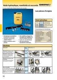
Characteristic curves – measured <strong>with</strong> HLP46, ϑ oil = 40 °C ±5°C (104 °F ±41 °F)<br />
Pressure differential in bar (PSI)<br />
14.0<br />
(203)<br />
12.0<br />
(174)<br />
10.0<br />
(145)<br />
8.0<br />
(116)<br />
6.0<br />
(87)<br />
4.0<br />
(58)<br />
2.0<br />
(29.0)<br />
0<br />
0<br />
Δp-q V -characteristic curves<br />
20<br />
(5.3)<br />
40<br />
(10.6)<br />
60<br />
(15.9)<br />
Flow in L/min (GPM)<br />
80<br />
(21.1)<br />
100<br />
(26.4)<br />
10<br />
9<br />
8<br />
7<br />
6<br />
5<br />
4<br />
3<br />
2<br />
1<br />
120<br />
(31.7)<br />
Direction of flow<br />
Symbols P – A P – B A – T B – T<br />
A, B 3 3 – –<br />
C 3 3 4 5<br />
D, Y 5 5 6 6<br />
E 1 1 4 4<br />
F 2 3 7 4<br />
G 3 3 6 7<br />
H 1 1 6 7<br />
J 1 1 3 3<br />
L 2 2 3 5<br />
M 1 1 4 5<br />
P 4 2 5 7<br />
Q 1 2 1 3<br />
R 3 6 4 –<br />
T 3 3 6 7<br />
U, V 2 2 3 3<br />
W 2 2 4 5<br />
Op. pos. P – A B – A A – T P – T<br />
R – 9 – –<br />
Centre pos. P – A P – B B – T A – T P – T<br />
F 4 — — 9 9<br />
P — 5 8 — 10<br />
G, T — — 9<br />
H — — 3<br />
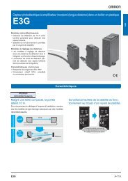
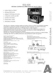
Performance limits: DC – measured <strong>with</strong> HLP46, ϑ oil = 40 °C ±5°C (104 °F ±41 °F)<br />
The performance limits shown are valid when the valve is used<br />
<strong>with</strong> two directions of fl ow (e.g. from P to A <strong>with</strong> simultaneous<br />
return fl ow from B to T).<br />
Due to the fl ow forces occuring <strong>with</strong>in the <strong>valves</strong>, the permissbile<br />
switching performance limits can be signifi cantly lower <strong>with</strong> only<br />
one direction of fl ow (e.g. from P to A <strong>and</strong> port B blocked)! (For<br />
these applications, please consult us.)<br />
The performance limit was determined <strong>with</strong> the solenoids at their<br />
operating temperature, 10 % under voltage <strong>and</strong> <strong>with</strong> no pre-loading<br />
of the tank.<br />
Operating pressure in bar (PSI)<br />
300<br />
(4350)<br />
250<br />
(3625)<br />
200<br />
(2900)<br />
150<br />
(2175)<br />
100<br />
(1450)<br />
50<br />
(725)<br />
8 10<br />
7<br />
6<br />
5<br />
8<br />
4<br />
1<br />
2<br />
3<br />
9<br />
Char. curve Symbols<br />
1 C, C/O, C/OF<br />
D, D/O, D/OF<br />
Y, M<br />
2 E<br />
3 A/O, A/OF<br />
L, U, J, Q, W<br />
4 H<br />
5 1) R, L 2) , U 2)<br />
6 G<br />
7 T<br />
8 F, P<br />
9 A, B<br />
10 V<br />
0<br />
0<br />
20<br />
(5.3)<br />
40<br />
(10.6)<br />
60<br />
(15.9)<br />
80<br />
(21.1)<br />
100<br />
(26.4)<br />
120<br />
(31.7)<br />
1)<br />
Return fl ow<br />
(independent of the area ratio)<br />
2)<br />
Only the center position<br />
Flow in L/min (GPM)
RA 23327/02.03 | WE 10 ../.C Industrial Hydraulics | <strong>Bosch</strong> <strong>Rexroth</strong> Corp. 7/12<br />
Performance limits: AC – measured <strong>with</strong> HLP46, ϑ oil = 40 °C ±5°C (104 °F ±41 °F)<br />
Operating pressure in bar (PSI)<br />
Operating pressure in bar (PSI)<br />
300<br />
(4350)<br />
250<br />
(3625)<br />
200<br />
(2900)<br />
150<br />
(2175)<br />
100<br />
(1450)<br />
50<br />
(725)<br />
0<br />
0<br />
300<br />
(4350)<br />
250<br />
(3625)<br />
200<br />
(2900)<br />
150<br />
(2175)<br />
100<br />
(1450)<br />
50<br />
(725)<br />
0<br />
0<br />
4<br />
9 7<br />
20<br />
(5.3)<br />
20<br />
(5.3)<br />
6<br />
7<br />
9<br />
6<br />
40<br />
(10.6)<br />
60<br />
(15.9)<br />
80<br />
(21.1)<br />
Flow in L/min (GPM)<br />
8<br />
4<br />
11 2 1<br />
10<br />
40<br />
(10.6)<br />
60<br />
(15.9)<br />
80<br />
(21.1)<br />
Flow in L/min (GPM)<br />
5<br />
7<br />
100<br />
(26.4)<br />
3<br />
100<br />
(26.4)<br />
120<br />
(31.7)<br />
120<br />
(31.7)<br />
Char. curve Symbols<br />
1 C, C/O, C/OF<br />
D, D/O, D/OF<br />
Y<br />
2 E, L,<br />
U, Q, W<br />
3 M<br />
4 A, B<br />
5 A/O, A/OF, J<br />
6 G<br />
7 F, P<br />
8 V<br />
9 T<br />
10 H<br />
11 R<br />
12 1) L, U<br />
1)<br />
Only the centre position<br />
42 V, 50 Hz; 110 V, 50 Hz; 120 V, 60 Hz;<br />
127 V, 50 Hz; 220 V, 50 Hz; 240 V, 60 Hz<br />
Operating pressure in bar (PSI)<br />
300<br />
(4350)<br />
250<br />
(3625)<br />
200<br />
(2900)<br />
150<br />
(2175)<br />
100<br />
(1450)<br />
50<br />
(725)<br />
0<br />
0<br />
20<br />
(5.3)<br />
2 5 6<br />
1<br />
40 60 80<br />
(10.6) (15.9) (21.1)<br />
Flow in L/min (GPM)<br />
4<br />
3<br />
100<br />
(26.4)<br />
120<br />
(31.7)<br />
Char. curve Symbols<br />
1 C, C/O, C/OF<br />
D, D/O, D/OF<br />
Y<br />
2 A/O, A/OF<br />
3 E<br />
4 M<br />
5 V<br />
6 H<br />
42 V, 60 Hz; 110 V, 60 Hz;<br />
127 V, 60 Hz; 220 V, 60 Hz<br />
Performance limits for other spools<br />
on request!
8/12 <strong>Bosch</strong> <strong>Rexroth</strong> Corp. | Industrial Hydraulics WE 10 ../.C | RA 23327/02.03<br />
Unit dimensions: DC – dimensions in millimeters (inches)<br />
Individual connection<br />
15 (0.59)<br />
117 (4.61)<br />
12<br />
1/2” NPT<br />
5<br />
A<br />
8 4 15 4<br />
9 12<br />
Ø 11<br />
(0.43)<br />
B<br />
6<br />
123 (4.84)<br />
40<br />
(1.57)<br />
15 (0.59)<br />
30<br />
(1.18)<br />
5.3<br />
(0.21)<br />
75<br />
(2.95)<br />
Ø 6.6 (0.26)<br />
121.3 (4.78)<br />
26<br />
(1.02)<br />
201.3 (7.93)<br />
80 (3.15)<br />
175.3 (6.90)<br />
16<br />
201.3 (7.93) 75<br />
296.6 (11.68)<br />
(2.95)<br />
5.3<br />
(0.21)<br />
14<br />
7 19 2 1 92.2 (3.63) 3<br />
7 13<br />
54<br />
(2.13)<br />
19.1<br />
(0.75)<br />
70 (2.76)<br />
46<br />
(1.81)<br />
TA<br />
P<br />
A B TB<br />
18<br />
17<br />
16<br />
(0.63)<br />
50 (1.97)<br />
1/2” NPT<br />
16<br />
12<br />
11<br />
10<br />
157 (6.18)<br />
Central connection<br />
114.5 (4.51)<br />
97.5 (3.84)<br />
1/2” NPT<br />
3.93<br />
(100)<br />
1/2" NPT<br />
15<br />
4.84<br />
(123)<br />
2.66<br />
(67.5)<br />
1.55<br />
(39.5)<br />
3.68<br />
(93.5)<br />
0.01/100 mm<br />
0.0004/4.0 in.<br />
32<br />
(R max 4)<br />
Required surface finish<br />
of the mating piece
RA 23327/02.03 | WE 10 ../.C Industrial Hydraulics | <strong>Bosch</strong> <strong>Rexroth</strong> Corp. 9/12<br />
Unit dimensions: DC – dimensions in millimeters (inches)<br />
1 3-position valve 1)<br />
2 2-position valve <strong>with</strong><br />
1 solenoid (A, C, D, EA...) 1)<br />
3 2-position valve <strong>with</strong><br />
1 solenoid (B, Y, EB...) 1)<br />
4 Cover for valve <strong>with</strong> 1 solenoid<br />
5 Solenoid “a” (plug-in connector<br />
color grey)<br />
6 Solenoid “b” (plug-in connector<br />
color black)<br />
7 Space required to remove the coil<br />
8 Plug-in connector <strong>with</strong>out circuitry<br />
to DIN EN 175 301-803 2)<br />
9 Plug-in connector <strong>with</strong> circuitry<br />
to DIN EN 175 301-803 2)<br />
10 Cable gl<strong>and</strong> Pg 16 “DL”<br />
11 Plug-in connector (plug-in connector<br />
color red, must be ordered separately,<br />
Material No. R900005538)<br />
12 Space required to remove the<br />
plug-in connector<br />
13 H<strong>and</strong> override “N9” (st<strong>and</strong>ard) –<br />
the h<strong>and</strong> override can only be<br />
operated up to a max. tank pressure of<br />
50 bar (725 PSI) – avoid damage to the<br />
h<strong>and</strong> override <strong>pin</strong> bore!<br />
14 Dimension for h<strong>and</strong> override “N”<br />
15 Name plate<br />
16 Identical seal rings for ports A, B, P,<br />
TA, TB (for <strong>valves</strong> <strong>with</strong> cartridge<br />
throttle: O-ring in the P port)<br />
17 Additional T connection (TB) can<br />
be used <strong>with</strong> manifolds where this<br />
connection is required.<br />
18 Porting pattern to DIN 24 340 form A,<br />
ISO 4401 <strong>and</strong> CETOP–RP 121 H.<br />
Subplates<br />
G 66/01(/12), G 3/8 (SAE-6; 9/16-18)<br />
G 67/01(/12), G 1/2 (SAE-8; 3/4-16)<br />
G 534/01(/12), G 3/4 (SAE-12; 1-1/16-12)<br />
to catalog sheet RE 45 054 <strong>and</strong><br />
Valve fixing screws<br />
M6 x 40 DIN 912-10.9<br />
(1/4 - 20 UNC x 1-1/2”),<br />
M A = 15.5 Nm (11.43 lb-ft),<br />
must be ordered separately.<br />
19 Tightening torque M A = 6 + 2 Nm<br />
(4.43 + 1.48 lb-ft)<br />
1)<br />
Dim. <strong>with</strong>out h<strong>and</strong> override <strong>and</strong> <strong>with</strong><br />
protected h<strong>and</strong> override “N9”<br />
2)<br />
Must be ordered separately,<br />
see page 3.<br />
Terminal allocation for the central<br />
connection:<br />
For 1 solenoid:<br />
Solenoid al<strong>way</strong>s to terminal 1 <strong>and</strong> 2<br />
Earth to terminal PE<br />
For 2 solenoids:<br />
Solenoid “a” to terminals 1 <strong>and</strong> 2<br />
Solenoid “b” to terminals 3 <strong>and</strong> 4<br />
Earth to terminal PE
10/12 <strong>Bosch</strong> <strong>Rexroth</strong> Corp. | Industrial Hydraulics WE 10 ../.C | RA 23327/02.03<br />
Unit dimensions: AC – dimensions in millimeters (inches)<br />
Individual connection<br />
117 (4.61) 15 (0.59)<br />
1/2” NPT<br />
12 5<br />
A<br />
8 4 15 4<br />
9 12<br />
Ø 11<br />
(0.43)<br />
B<br />
6<br />
123 (4.84)<br />
15 (0.59)<br />
40<br />
(1.57)<br />
30<br />
(1.18)<br />
15<br />
(0.59)<br />
46<br />
(1.81)<br />
Ø 6.6<br />
(0.26) 26 80 (3.15)<br />
(1.02)<br />
95.8 (3.77)<br />
149.8 (5.90)<br />
175.8 (6.92)<br />
175.8 (6.92)<br />
(245,6)<br />
16<br />
46<br />
(1.81)<br />
15<br />
(0.59)<br />
14<br />
7 19 2 1 92.2 (3.63)<br />
3 7 13<br />
54<br />
(2.13)<br />
19.1<br />
(0.75)<br />
70 (2.76)<br />
46<br />
(1.81)<br />
TA<br />
P<br />
A B TB<br />
18<br />
17<br />
16<br />
(0.63)<br />
Central connection<br />
50 (1.97)<br />
1/2” NPT<br />
12<br />
11<br />
10<br />
16<br />
157 (6.18)<br />
114.5 (4.51)<br />
97.5 (3.84)<br />
1/2” NPT<br />
3.93<br />
(100)<br />
1/2" NPT<br />
15<br />
4.84<br />
(123)<br />
2.66<br />
(67.5)<br />
1.55<br />
(39.5)<br />
3.68<br />
(93.5)<br />
0.01/100 mm<br />
0.0004/4.0 in.<br />
32<br />
(R max 4)<br />
Required surface finish<br />
of the mating piece
RA 23327/02.03 | WE 10 ../.C Industrial Hydraulics | <strong>Bosch</strong> <strong>Rexroth</strong> Corp. 11/12<br />
Unit dimensions: AC – dimensions in millimeters (inches)<br />
1 3-position valve 1)<br />
2 2-position valve <strong>with</strong> 1 solenoid<br />
(A, C, D, EA...) 1)<br />
3 2-position valve <strong>with</strong> 1 solenoid<br />
(B, Y, EB...) 1)<br />
4 Cover for valve <strong>with</strong> 1 solenoid<br />
5 Solenoid “a” (plug-in connector<br />
color grey)<br />
6 Solenoid “b” (plug-in connector<br />
color black)<br />
7 Space required to remove the coil<br />
8 Plug-in connector <strong>with</strong>out circuitry<br />
to DIN EN 175 301-803 2)<br />
9 Plug-in connector <strong>with</strong> circuitry<br />
to DIN EN 175 301-803 2)<br />
10 Cable gl<strong>and</strong> Pg 16 “DL”<br />
11 Plug-in connector (plug-in connector<br />
color red, must be ordered separately,<br />
Material No. R900005538)<br />
12 Space required to remove the<br />
plug-in connector<br />
13 H<strong>and</strong> override “N9” (st<strong>and</strong>ard) –<br />
the h<strong>and</strong> override can only be<br />
operated up to a max. tank pressure<br />
of 50 bar (725 PSI) – avoid damage<br />
to the h<strong>and</strong> override <strong>pin</strong> bore!<br />
14 Dimension for h<strong>and</strong> override “N”<br />
15 Name plate<br />
16 Identical seal rings for ports A, B, P,<br />
TA, TB (for <strong>valves</strong> <strong>with</strong> cartridge<br />
throttle: O-ring in the P port)<br />
17 Additional T connection (TB) can<br />
be used <strong>with</strong> manifolds where this<br />
connection is required.<br />
18 Porting pattern to DIN 24 340 form A,<br />
ISO 4401 <strong>and</strong> CETOP–RP 121 H.<br />
Subplates<br />
G 66/01, G 3/8 (SAE-6; 9/16-18)<br />
G 67/01, G 1/2 (SAE-8; 3/4-16)<br />
G 534/01, G 3/4 (SAE-12; 1-1/16-12)<br />
to catalog sheet RE 45 054 <strong>and</strong><br />
Valve fixing screws<br />
M6 x 40 DIN 912-10.9<br />
(1/4 - 20 UNC x 1-1/2”),<br />
M A = 15.5 Nm (11.43 lb-ft),<br />
must be ordered separately.<br />
19 Tightening torque M A = 6 + 2 Nm<br />
(4.43 + 1.48 lb-ft)<br />
1)<br />
Dim. <strong>with</strong>out h<strong>and</strong> override <strong>and</strong> <strong>with</strong><br />
protected h<strong>and</strong> override “N9”<br />
2)<br />
Must be ordered separately,<br />
see page 3.<br />
Terminal allocation for the central<br />
connection:<br />
For 1 solenoid:<br />
Solenoid al<strong>way</strong>s to terminal 1 <strong>and</strong> 2<br />
Earth to terminal PE<br />
For 2 solenoids:<br />
Solenoid “a” to terminals 1 <strong>and</strong> 2<br />
Solenoid “b” to terminals 3 <strong>and</strong> 4<br />
Earth to terminal PE
12/12 <strong>Bosch</strong> <strong>Rexroth</strong> Corp. | Industrial Hydraulics WE 10 ../.C | RA 23327/04.04<br />
Plug-in connectors to DIN EN 175 301-803 for component plug "K4"<br />
For further<br />
plug-in connectors<br />
see RE 08006<br />
Material No.<br />
Valve<br />
side Color Without circuitry<br />
With indicator light<br />
12 … 240 V<br />
With rectifi er<br />
12 … 240 V<br />
With indicator light <strong>and</strong><br />
Z-diode protective circuit<br />
24 V<br />
a grey R900074683 — — —<br />
b black R900074684 — — —<br />
a/b black — R900057292 R900313933 R900310995<br />
<strong>Bosch</strong> <strong>Rexroth</strong> Corp.<br />
Industrial Hydraulics<br />
2315 City Line Road<br />
Bethlehem, PA 18017-2131<br />
USA<br />
Telephone (610) 684-8300<br />
Facsimile (610) 694-8467<br />
www.boschrexroth-us.com<br />
© This document, as well as the data, specifi cations <strong>and</strong> other<br />
information set forth in it, are the exclusive property of <strong>Bosch</strong> <strong>Rexroth</strong><br />
Corporation. Without their consent it may not be reproduced or given to<br />
third parties.<br />
The data specifi ed above only serve to describe the product. No<br />
statements concerning a certain condition or suitability for a certain<br />
application can be derived from our information. The information given<br />
does not release the user from the obligation of own judgment <strong>and</strong><br />
verifi cation. It must be remembered that our products are subject to a<br />
natural process of wear <strong>and</strong> aging.