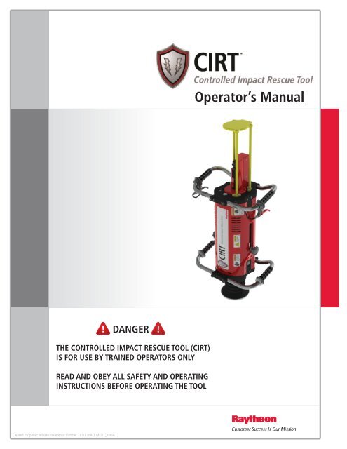
Controlled Impact Rescue Tool (CIRT) Operator's Manual - Raytheon
Controlled Impact Rescue Tool (CIRT) Operator's Manual - Raytheon
Controlled Impact Rescue Tool (CIRT) Operator's Manual - Raytheon
You also want an ePaper? Increase the reach of your titles
YUMPU automatically turns print PDFs into web optimized ePapers that Google loves.
Cleared for public release. Reference number 2010-364. CMD11_00342<br />
DANGER<br />
THE CONTROLLED IMPACT RESCUE TOOL (<strong>CIRT</strong>)<br />
IS FOR USE BY TRAINED OPERATORS ONLY<br />
READ AND OBEY ALL SAFETY AND OPERATING<br />
INSTRUCTIONS BEFORE OPERATING THE TOOL<br />
Operator’s <strong>Manual</strong>
________________________________________________________<br />
Acknowledgement<br />
The <strong>Controlled</strong> <strong>Impact</strong> <strong>Rescue</strong> <strong>Tool</strong>s (<strong>CIRT</strong>) was developed in cooperation with the<br />
US Department of Homeland Security, Science and Technology Directorate.<br />
________________________________________________________<br />
2
DANGER<br />
SAFETY WARNINGS_____________________________________<br />
DANGER<br />
THIS TOOL IS TO BE USED ONLY BY PROPERLY TRAINED<br />
OPERATORS. YOU MUST COMPLETE THE RAYTHEON <strong>CIRT</strong><br />
TRAINING PROGRAM BEFORE HANDLING, LOADING, OR<br />
OPERATING THIS TOOL. ATTEMPTING TO HANDLE OR<br />
OPERATE THIS TOOL WITHOUT PROPER TRAINING CAN<br />
RESULT IN SERIOUS INJURY OR EVEN DEATH TO THE TOOL<br />
OPERATORS AND BYSTANDERS.<br />
DANGER<br />
SAFETY WARNINGS_____________________________________<br />
3
SAFETY INSTRUCTIONS__________________________________ CAUTION<br />
Acceptable Materials<br />
The <strong>CIRT</strong> is suitable for use on the<br />
following materials only:<br />
� Reinforced Concrete walls and floors<br />
between 4” & 8” in thickness<br />
� Reinforced Concrete ceilings 5” thick<br />
or less<br />
Never use the <strong>CIRT</strong> on any other materials.<br />
Failure to follow these guidelines may damage<br />
the <strong>CIRT</strong> and cause serious injury to operators<br />
and bystanders.<br />
Unacceptable Materials<br />
Never use the <strong>CIRT</strong> on non-reinforced<br />
concrete. Failure to follow this could result in<br />
destabilization of the intended breach, damage<br />
to the <strong>CIRT</strong>, and/or injury to operators and<br />
bystanders.<br />
<strong>CIRT</strong> Load Safety<br />
1. Only use approved <strong>CIRT</strong> cartridges in<br />
the <strong>CIRT</strong> tool. The use of any other<br />
cartridge is strictly prohibited and may<br />
damage the tool and cause serious injury<br />
to operators.<br />
2. Never, under any circumstances, store or<br />
transport the tool in a loaded condition.<br />
3. Always transport and store <strong>CIRT</strong><br />
charges in an approved container.<br />
Leave the charges in the container until<br />
ready for use. The storage container for<br />
the charges has been specially designed to<br />
preclude accidental discharge. It also<br />
protects the charges from contamination<br />
and damage, ensuring proper operation.<br />
Operating Area Safety<br />
1. Ensure the proper personal protective<br />
equipment is being worn by operators<br />
and any bystanders as necessary. Loud<br />
noise and flying debris from the operation<br />
of the <strong>CIRT</strong> has the potential to injure<br />
operators as well as others nearby. Ensure<br />
everyone near the operating area is<br />
adequately protected.<br />
2. Keep the breaching area clear of<br />
unnecessary bystanders, equipment, and<br />
materials that may interfere with safe<br />
operation of the <strong>CIRT</strong>. Operating the<br />
<strong>CIRT</strong> in an area with excessive debris,<br />
obstacles, and unnecessary personnel may<br />
affect your ability to handle and operate<br />
the tool safely.<br />
3. Never operate the <strong>CIRT</strong> around<br />
potentially flammable or explosive<br />
materials or conditions. The combustion<br />
products vented by the <strong>CIRT</strong> have the<br />
potential for igniting flammable materials<br />
nearby. Take this into consideration when<br />
selecting and preparing an area for a<br />
breach.<br />
<strong>Tool</strong> Handling Safety<br />
1. Always be sure the <strong>CIRT</strong> is operating<br />
properly before attempting to use it.<br />
Follow the Functionality Test outlined in<br />
the Operating Instructions section on<br />
page 7 of this manual prior to use.<br />
2. Do not load the tool until you are ready<br />
to operate it. Only load the tool once it<br />
has been set up in the immediate vicinity<br />
of where it is to be operated. If use is<br />
aborted after the cartridge is loaded,<br />
unload the tool before continuing. Do<br />
not store the <strong>CIRT</strong> loaded. Leaving the<br />
tool unattended while loaded may lead to<br />
accidental discharge by other operators or<br />
bystanders with the potential for injury.<br />
3. Once the tool is loaded do not place any<br />
body part or foreign object in or near<br />
the opening for the <strong>Impact</strong>or. Failure to<br />
obey this could lead to serious injury<br />
and/or damage to the <strong>CIRT</strong>.<br />
SAFETY INSTRUCTIONS__________________________________ CAUTION<br />
4
CAUTION<br />
SAFETY INSTRUCTIONS__________________________________<br />
4. Do not allow anyone who has not been<br />
trained operate the <strong>CIRT</strong>. This manual<br />
is not designed to fully train operators of<br />
the <strong>CIRT</strong>. All operators must complete the<br />
approved operator training before<br />
operating the tool.<br />
5. Using the <strong>CIRT</strong> in a poorly ventilated<br />
area, cleaning the <strong>CIRT</strong>, or handling the<br />
cartridges may result in exposure to<br />
harmful substances. Have adequate<br />
ventilation at all times when operating<br />
or cleaning the <strong>CIRT</strong> and wash<br />
thoroughly after exposure.<br />
Misfire Procedure<br />
If the <strong>CIRT</strong> does not fire after pulling the<br />
triggers, continue to stand in the firing<br />
position with the tool firmly pressed against<br />
the work surface for a minimum of 5<br />
seconds.<br />
After 5 seconds have passed, return the tool<br />
to a safe loading position and eject the<br />
misfired cartridge. Immediately place the<br />
cartridge in a safe location away from<br />
flammable materials and other cartridges.<br />
Placing it in a bucket of water or other nonflammable<br />
liquid is preferable prior to<br />
disposal.<br />
Ensure the Receiver Safety Lever was in the<br />
“Fire” position.<br />
Load a new cartridge in the <strong>CIRT</strong> and<br />
attempt to operate it again. If a second<br />
cartridge also misfires, discontinue use of<br />
the tool until a cause can be determined.<br />
Warning<br />
Inspect tool before every use. STOP USE if<br />
any component or fastener becomes loose or<br />
is missing<br />
CAUTION<br />
SAFETY INSTRUCTIONS__________________________________<br />
5
<strong>CIRT</strong> OVERVIEW_________________________________________<br />
<strong>CIRT</strong> OVERVIEW_________________________________________<br />
6
OPERATING INSTRUCTIONS______________________________<br />
DANGER<br />
Whenever approaching the tool for any<br />
reason, always begin by opening the bolt and<br />
visually ensuring that no cartridge is present.<br />
Functionality Test<br />
1. After checking to be sure that the <strong>CIRT</strong> is<br />
not loaded, close the Receiver Bolt<br />
without inserting a cartridge and engage<br />
the Receiver Safety Lever into the “Fire”<br />
position.<br />
2. Depress the Secondary Trigger, and release<br />
it. Ensure it moves freely and returns fully.<br />
If it does not move smoothly or return fully<br />
discontinue use of the tool.<br />
3. Depress the Secondary Trigger and hold it<br />
in place. Now depress the Firing Trigger,<br />
listening carefully for operation of the<br />
firing pin. The firing pin should release<br />
with an audible click. If the firing pin does<br />
not operate when both triggers are fully<br />
depressed discontinue use of the tool.<br />
Refer to the Firing Cable Adjustment<br />
Procedure on page 19 before attempting to<br />
use the <strong>CIRT</strong>.<br />
4. Release both triggers, ensuring that the<br />
Firing Trigger moves smoothly and returns<br />
fully. If it does not discontinue use of the<br />
tool immediately.<br />
5. Open the Bolt to reset the firing pin and<br />
close it again without inserting a<br />
cartridge. With the Secondary Trigger not<br />
depressed attempt to depress only the<br />
Firing Trigger. Listen for the firing pin to<br />
release. If the Firing Trigger alone is able<br />
to release the firing pin without the<br />
Secondary Trigger being depressed,<br />
discontinue use of the tool immediately.<br />
Refer to the Firing Cable Adjustment<br />
Procedure on page 19 before attempting to<br />
use the <strong>CIRT</strong>.<br />
6. With the Bolt still closed in the firing<br />
position and no cartridge in the chamber,<br />
move the Receiver Safety Lever to the<br />
“Safe” position.<br />
7. Depress the Secondary Trigger and hold it<br />
in place. Now depress the Firing Trigger,<br />
listening carefully for operation of the<br />
firing pin. The firing pin should not<br />
operate. This tests the operation of the<br />
Receiver Safety Lever. If the firing pin<br />
operates when both triggers are depressed<br />
with the receiver safety mechanism in the<br />
“Safe” position discontinue use of the tool<br />
immediately.<br />
8. Release both triggers, ensuring that the<br />
Firing Trigger moves smoothly and returns<br />
fully. If it does not discontinue use of the<br />
tool immediately.<br />
9. Open the Receiver Bolt. Using the<br />
<strong>Impact</strong>or Reset Handles on the sides of the<br />
<strong>CIRT</strong> reset the <strong>Impact</strong>or into the upper<br />
(ready) position. Ensure that it moves<br />
freely into position and remains there after<br />
handles have been released. If it does not<br />
move smoothly or does not remain<br />
unassisted in the ready position, consult the<br />
Troubleshooting Chart on page 9.<br />
After the <strong>CIRT</strong> has passed the Functionality<br />
Test it is ready to be used. If the <strong>CIRT</strong> does<br />
not pass the test even after consulting the<br />
Troubleshooting Chart and Firing Cable<br />
Adjustment Procedures discontinue use of<br />
the tool and contact your sales<br />
representative.<br />
OPERATING INSTRUCTIONS______________________________<br />
7
OPERATING INSTRUCTIONS______________________________<br />
DANGER<br />
Before operating the <strong>CIRT</strong> ensure that all<br />
operators and bystanders are wearing proper<br />
Personal Protective Equipment (PPE) and are<br />
notified that you will be firing the <strong>CIRT</strong><br />
<strong>CIRT</strong> Operation<br />
1. With the <strong>CIRT</strong> in a safe loading position,<br />
move the Receiver Safety Lever to the<br />
“Safe” position. Open the Receiver Bolt.<br />
2. Reset the <strong>Impact</strong>or to the top of the stroke<br />
using the <strong>Impact</strong>or Reset Handles on the<br />
side of the <strong>CIRT</strong>. Ensure the handles<br />
return to their starting point at the bottom<br />
of the stroke.<br />
3. Insert an appropriate <strong>CIRT</strong> cartridge into<br />
the Receiver. Close the Bolt.<br />
4. Once both operators are ready and the<br />
location of the breach has been decided<br />
move the Receiver Safety Lever to the<br />
“Fire” position.<br />
5. Pick up the <strong>CIRT</strong> tool by the front and rear<br />
handles. It is important that both operators<br />
grasp only the handles with no fingers<br />
above or touching the triggers until the<br />
<strong>CIRT</strong> is in position.<br />
6. Place the tool against the wall for the<br />
breach. Ensure both operators have an<br />
adequate stance and grip for the expected<br />
recoil of the <strong>CIRT</strong>.<br />
7. Once both operators are ready, the operator<br />
on the left side of the tool may actuate the<br />
black Secondary Trigger, thereby<br />
disengaging the lockout on the Firing<br />
Trigger. The secondary operator should<br />
notify the firing trigger operator that the<br />
trigger is fully depressed.<br />
8. Once the firing operator has decided that<br />
everything is properly in position, and has<br />
determined that the secondary operator is<br />
ready, they may then actuate the Firing<br />
Trigger. This will discharge the <strong>CIRT</strong>.<br />
9. Do not attempt to keep the <strong>CIRT</strong> in<br />
contact with the wall while discharging.<br />
Make sure neither operator, or any<br />
bystanders, are standing in the expected<br />
recoil path of the <strong>CIRT</strong>. The recoil force<br />
of the <strong>CIRT</strong> is too high to be forcibly<br />
stopped. Operators should only control the<br />
path of the <strong>CIRT</strong> during recoil.<br />
10. Once the <strong>CIRT</strong> has been fired, return it to a<br />
safe loading position. Open the Bolt to<br />
eject the shell and keep it open.<br />
11. This completes a full firing sequence of the<br />
<strong>CIRT</strong>. Repeat steps 2-10 until desired<br />
breach size has been achieved.<br />
Post-Breaching Inspection and Storage<br />
Instructions<br />
It is important to properly inspect and store the<br />
<strong>CIRT</strong> after each use to ensure it will remain in<br />
good working order until the next deployment.<br />
1. After each deployment of the <strong>CIRT</strong><br />
inspect the entire unit for obvious signs<br />
of damage. Closely inspect the covers,<br />
handles, Safety Cage, Receiver, triggers,<br />
and any other visible components to see<br />
that they are free from damage and<br />
lodged debris.<br />
2. Clean the <strong>CIRT</strong> tool in accordance with<br />
the procedures outlined in the<br />
Maintenance and Cleaning Instructions<br />
on page 10.<br />
3. Perform the Functionality Test per the<br />
instructions on page 7 prior to storing the<br />
<strong>CIRT</strong> to ensure it is still fully<br />
functioning.<br />
4. Every 6 months of continuous storage the<br />
<strong>CIRT</strong> should be inspected and cleaned<br />
again to ensure continued reliability and<br />
readiness.<br />
OPERATING INSTRUCTIONS______________________________<br />
8
TROUBLESHOOTING_____________________________________<br />
<strong>CIRT</strong> Troubleshooting<br />
Problem Possible Reason Solution<br />
<strong>CIRT</strong> Fails to Fire<br />
Piston Head Difficult<br />
to Reset<br />
Insufficient<br />
Penetration into<br />
Target Material<br />
Excessive<br />
Penetration into<br />
Target Material<br />
Excessive Recoil<br />
No Round Loaded Ensure there is a <strong>CIRT</strong> cartridge loaded in the tool<br />
Receiver Safety Lever Engaged<br />
Cartridge Misfire<br />
Trigger Safety Catch Failure<br />
Piston/<strong>Impact</strong>or Assembly Dirty<br />
Piston/<strong>Impact</strong>or Assembly<br />
Damaged<br />
Target Material Too Hard<br />
Piston Not Fully Reset<br />
Target Material Too Soft<br />
Target Material Too Hard<br />
Damage to Damping Mechanism<br />
Ensure the Receiver Safety Lever is set to the "Fire"<br />
position<br />
Follow the "Misfire Procedure" in the Safety Instructions<br />
on page 5<br />
Ensure the Trigger Safety Mechanism is operating<br />
properly as outlined in the Functionality Test on page 7<br />
Remove Piston/<strong>Impact</strong>or assembly and clean.<br />
Reassemble and recheck<br />
Remove and replace Piston/<strong>Impact</strong>or assembly<br />
Ensure the <strong>CIRT</strong> is being used only on approved target<br />
materials, listed in the Safety Instructions on page 4<br />
Fully reset before each firing. Ensure the ball detents<br />
are holding the piston in the firing position.<br />
Ensure the <strong>CIRT</strong> is being used only on approved target<br />
materials, listed in the Safety Instructions on page 4<br />
Ensure the <strong>CIRT</strong> is being used only on approved target<br />
materials, listed in the Safety Instructions on page 4<br />
Discontinue use of the <strong>CIRT</strong> Immediately and contact<br />
your sales representative<br />
If after performing the checks described in the troubleshooting table the <strong>CIRT</strong> does not perform to<br />
specifications, or if you discover excessive wear or damage to any parts not covered in the<br />
maintenance instructions, discontinue use of the tool immediately and contact your sales<br />
representative for additional assistance.<br />
Record any <strong>CIRT</strong> malfunctions and the corrective action taken in the <strong>CIRT</strong> Maintenance Log (page 22.)<br />
TROUBLESHOOTING_____________________________________<br />
9
MAINTENANCE AND CLEANING__________________________<br />
Cleaning Instructions – Every Use<br />
Ensure that you are wearing adequate<br />
personal protective equipment for the tools<br />
and cleaning products you are using.<br />
Foot, <strong>Impact</strong>or Guide Sleeve<br />
1. Ensure the <strong>Impact</strong>or is at the bottom of<br />
the stroke. If it has been reset, place the<br />
<strong>CIRT</strong> on the ground in the vertical<br />
position and tap the Foot on the ground to<br />
dislodge the <strong>Impact</strong>or from the internal<br />
retention mechanism.<br />
2. Remove the Foot as outlined in Section 1<br />
of the Maintenance Procedures.<br />
a. Check the area inside the Foot for<br />
excessive dirt and debris.<br />
b. Clean the foot using damp towel<br />
and dry thoroughly.<br />
3. Remove the <strong>Impact</strong>or Guide Sleeve as<br />
outlined in Section 2 of the Maintenance<br />
Procedures.<br />
a. Clean the Guide Sleeve using<br />
scour pad, wipe clean and dry<br />
thoroughly.<br />
DANGER<br />
IMPROPERLY MAINTAINED TOOLS CAN CAUSE SERIOUS INJURIES TO<br />
TOOL OPERATORS AND BYSTANDERS.<br />
FOLLOW ALL INSTRUCTIONS REGARDING PROPER MAINTENANCE<br />
PROCEDURES AND INTERVALS FOR THE <strong>CIRT</strong> TOOL.<br />
ALWAYS MAKE SURE THE <strong>CIRT</strong> IS NOT LOADED BEFORE PERFORMING<br />
ANY SERVICE OR REPAIR.<br />
<strong>Impact</strong>or Assembly and Inner Chamber<br />
4. Remove the <strong>Impact</strong>or Assembly as<br />
outlined in Section 3 of the Maintenance<br />
Procedures.<br />
a. Inspect <strong>Impact</strong>or Assembly<br />
(Piston Head, Piston Ring, Main<br />
Bumpers, and Trolley) Replace as<br />
needed.<br />
b. Clean entire <strong>Impact</strong>or using scour<br />
pad and wipe dry.<br />
c. Inside of Chamber – Clean with<br />
cleaning brush and dry<br />
thoroughly.<br />
5. Reinstall the <strong>Impact</strong>or Assembly into<br />
chamber as outlined in section 3 of the<br />
maintenance procedures.<br />
6. Install the Guide Sleeve as outlined in<br />
Section 2 of the maintenance procedures.<br />
7. Reinstall the Foot as outlined in Section 1<br />
of the maintenance procedures<br />
MAINTENANCE AND CLEANING__________________________<br />
10
MAINTENANCE AND CLEANING__________________________<br />
Main Body and Side Rails<br />
8. Remove the Main Body Covers as<br />
outlined in Section 4 of the Maintenance<br />
Procedures.<br />
a. Wipe clean and dry thoroughly.<br />
You will not be able to remove<br />
carbon scarring.<br />
9. Clean the Main Body of the <strong>CIRT</strong>.<br />
Blow the area out thoroughly with<br />
compressed air.<br />
a. Inspect the Main Body of the<br />
<strong>CIRT</strong> (Springs, Dampers, Cables,<br />
Bearings)<br />
10. Remove ONE Side Rail as directed in<br />
Section 5 of the Maintenance Procedures<br />
a. Clean Slide Rail mechanism with<br />
scour pad and wipe dry.<br />
b. Lightly oil (3-4 drops) inside<br />
track and move Slide Mechanism<br />
to spread thoroughly.<br />
c. Wipe excess oil.<br />
11. Reinstall Side Rail<br />
12. Repeat steps 3 and 4 for remaining rail<br />
13. Reinstall the Main Body Covers as<br />
directed in Section 4 of the Maintenance<br />
Procedures<br />
Receiver Mechanism<br />
14. Disassemble and clean the Receiver<br />
mechanism as directed in Section 6 of the<br />
Maintenance Procedures.<br />
If the <strong>CIRT</strong> is subjected to environmental<br />
conditions outside of normal usage in-depth<br />
cleaning of the tool is necessary. These<br />
conditions include, but are not limited to, use<br />
in a sandy environment and immersion in<br />
mud or water.<br />
MAINTENANCE AND CLEANING__________________________<br />
11
MAINTENANCE PROCEDURES__________________________<br />
Required <strong>Tool</strong>s for Maintenance:<br />
• Spanner Wrench, 1/4” Pin, Adjustable • Hex Driver, Ball End, 1/4” with screw-<br />
from 2” to 4-3/4”<br />
holder tip<br />
• Hex Driver, Ball End, 3/16” • Hex Driver, Ball End, 5/32”<br />
• Wrench, 1-1/4”, Open Ended • Screw Driver, Flat Tip, ¼”<br />
• Dead-Blow Hammer • Screw Driver, Phillips Head, #2<br />
• Bearing Extraction <strong>Tool</strong> TD93DW84 • Metal Hammer<br />
• Pin Punch, 3/16” diameter<br />
Additional Items Required:<br />
• Remington “Rem Action” Cleaner • Thread Locking Compound, Medium<br />
• Remington “Rem Oil” Lubricant • Compressed air<br />
• Anti-seize compound<br />
<strong>CIRT</strong> Maintenance Procedures<br />
Before performing any maintenance<br />
operation open the Bolt and verify that the<br />
<strong>CIRT</strong> is not loaded. Using two people place<br />
the <strong>CIRT</strong> horizontally on a sturdy work<br />
surface. Ensure you are wearing appropriate<br />
personal protective equipment for the tools<br />
you are using.<br />
Section 1 – Foot<br />
Removal and Reinstallation<br />
1. Remove the six (6) cap screws securing the<br />
Foot to the <strong>CIRT</strong> tool using the 3/16” hex<br />
driver (see Figure 1).<br />
2. To reinstall the Foot, line it up with the<br />
holes and tap it gently with the dead-blow<br />
hammer until it is seated against the front<br />
handle plate. Partially thread in all six (6)<br />
cap screws before tightening them in any<br />
order.<br />
Section 2 – <strong>Impact</strong>or Guide Sleeve<br />
Removal<br />
1. Remove the Foot as outlined in Section 1 –<br />
Foot.<br />
Figure 1 – Foot Removal<br />
Figure 2 – <strong>Impact</strong>or Guide Sleeve Removal<br />
MAINTENANCE PROCEDURES____________________________<br />
12
MAINTENANCE PROCEDURES____________________________<br />
2. Use the spanner wrench to remove the<br />
<strong>Impact</strong>or Guide Sleeve (see Figure 2). The<br />
sleeve unscrews counterclockwise from the<br />
<strong>Impact</strong>or Assembly Retaining Nut. A light<br />
tap from the dead-blow hammer on the<br />
spanner wrench may be necessary to<br />
disengage the collar.<br />
Reinstallation<br />
1. For reassembly, apply anti-seize compound<br />
to the threads and install the <strong>Impact</strong>or<br />
Guide Sleeve into the <strong>Impact</strong>or Assembly<br />
Retaining Nut while rotating clockwise<br />
until it is lightly seated. Use the spanner<br />
wrench to tighten. Several light taps from<br />
the dead-blow hammer on the spanner<br />
wrench may be necessary to fully secure<br />
the sleeve (see Figure 3).<br />
2. Reinstall the Foot as outlined in Section 1 –<br />
Foot.<br />
Section 3 –<strong>Impact</strong>or Assembly<br />
Removal<br />
1. Ensure the <strong>Impact</strong>or is at the bottom of the<br />
stroke. If it has been reset, place the <strong>CIRT</strong><br />
on the ground in the vertical loading<br />
position and tap the Foot on the ground to<br />
dislodge the <strong>Impact</strong>or from the internal<br />
retention mechanism.<br />
2. Remove the Foot and the <strong>Impact</strong>or Guide<br />
Sleeve as outlined in Sections 1 and 2.<br />
3. Remove the plugs covering the two (2)<br />
Piston Reset Screws and remove the screws<br />
with the 1/4” hex driver (see Figure 4).<br />
4. Using the spanner wrench, unscrew the<br />
<strong>Impact</strong>or Assembly Retaining Nut (see<br />
Figure 5). A light tap from the dead-blow<br />
hammer on the spanner wrench may be<br />
necessary to disengage the nut.<br />
5. Grasp the <strong>Impact</strong>or and slide the <strong>Impact</strong>or<br />
Assembly out of the tool (see Figure 6).<br />
Figure 3 – <strong>Impact</strong>or Guide Sleeve Reinstallation<br />
Figure 4 –Piston Reset Screws<br />
Figure 5 – <strong>Impact</strong>or Assembly Retaining Nut<br />
MAINTENANCE PROCEDURES____________________________<br />
13
MAINTENANCE PROCEDURES____________________________<br />
Disassembly<br />
1. With the <strong>Impact</strong>or Assembly removed from<br />
the <strong>CIRT</strong> tool, place it on a sturdy work<br />
surface in a block to hold it steady (see<br />
Figure 7). DO NOT CLAMP ANY PART<br />
OF THE IMPACTOR ASSEMBLY IN A<br />
VISE. Using the 3/16” pin punch and<br />
metal hammer, drive out the Roll Pin<br />
securing the Piston Head to the <strong>Impact</strong>or<br />
(see Figure 7).<br />
2. Unscrew the Piston Head from the<br />
<strong>Impact</strong>or with the spanner wrench and a 1-<br />
1/4” open ended wrench (see Figure 8).<br />
3. Remove the Long Bumper, Short Bumper,<br />
and Trolley from the <strong>Impact</strong>or (see Figure<br />
9)<br />
4. Remove the four (4) screws holding the<br />
Slide Bearing Retainer to the <strong>Impact</strong>or<br />
Assembly Retaining Nut (see Figure 10).<br />
Remove the Slide Bearing Retainer.<br />
5. Block the <strong>Impact</strong>or Assembly vertically (see<br />
Figure 11). Remove the two Slide Bearings<br />
by using the Bearing Extraction <strong>Tool</strong> as<br />
shown and lightly tapping with the metal<br />
hammer (see Figure 12). Inspect the Slide<br />
Bearings for excessive wear and replace if<br />
necessary.<br />
6. Once the Slide Bearings are removed the<br />
<strong>Impact</strong>or will slide free of the <strong>Impact</strong>or<br />
Assembly Retaining Nut.<br />
Reassembly<br />
1. Insert the new <strong>Impact</strong>or into the <strong>Impact</strong>or<br />
Assembly Retaining Nut in the same<br />
orientation as the one you just removed.<br />
2. Stand the <strong>Impact</strong>or and Retaining Nut<br />
upright and slide the halves of the Slide<br />
Bearings back into the Nut. Gently tap the<br />
Slide Bearings with the dead-blow hammer<br />
until they are seated (see Figure 13).<br />
3. Reinstall the Slide Bearing Retainer onto<br />
the <strong>Impact</strong>or Assembly Retaining Nut. Use<br />
the medium strength thread locking<br />
compound on the four (4) screws (see<br />
Figure 6 – <strong>Impact</strong>or Assembly Removal<br />
Figure 7 – Piston Head Roll Pin Removal<br />
Figure 8 – Piston Head Removal<br />
MAINTENANCE PROCEDURES____________________________<br />
14
MAINTENANCE PROCEDURES____________________________<br />
Figure 10). Start all four screws before<br />
tightening them down in any order. The<br />
first screws tightened may loosen as others<br />
are tightened. Go around and retighten all<br />
four screws several times until they remain<br />
tight.<br />
4. Reinstall the Long Bumper, Short Bumper,<br />
and Trolley in the correct sequence and<br />
orientation as shown in Figure 9.<br />
5. Reinstall the Piston Head onto the <strong>Impact</strong>or<br />
using the spanner wrench and 1- 1/4” open<br />
ended wrench (see Figure 8). Make sure<br />
they are tight by tapping the spanner<br />
wrench with the dead-blow hammer.<br />
6. Block the <strong>Impact</strong>or Assembly so it does not<br />
move around to prevent damage to the<br />
Piston Head. DO NOT CLAMP ANY<br />
PART OF THE IMPACTOR ASSEMBLY<br />
IN A VISE. Install a new Roll Pin into the<br />
Piston Head using the metal hammer and<br />
pin punch (see Figure 7). Note: Insert the<br />
roll pin into the enlarged hole on one<br />
side of the Piston Head which is intended<br />
to facilitate pin installation. Ensure that<br />
no portion of the Roll Pin protrudes beyond<br />
the hole at either end.<br />
Reinstallation<br />
1. Slide the <strong>Impact</strong>or Assembly into the<br />
<strong>CIRT</strong>. Ensure that the holes in the Trolley<br />
remain aligned with the holes in the Handle<br />
Frame for the Piston Reset Screws (see<br />
Figure 14). Push trolley into <strong>CIRT</strong> until the<br />
holes align.<br />
2. Apply two (2) drops of medium strength<br />
locking compound on the threads of the<br />
Piston Reset Screws. Install the Piston<br />
Reset Screws through the holes in the<br />
Handle Frame and into the Trolley (see<br />
Figure 4). Start both screws before fully<br />
tightening them.<br />
3. Thread <strong>Impact</strong>or Assembly Retaining Nut<br />
into <strong>CIRT</strong>. Apply two (2) drops of medium<br />
strength Loctite to the Chamber End Nut<br />
threads.<br />
Figure 9 – Piston, Bumpers, and Trolley Order<br />
Figure 10 – Slide Bearing Retainer<br />
Figure 11 – Supported <strong>Impact</strong>or Assembly<br />
MAINTENANCE PROCEDURES____________________________<br />
15
MAINTENANCE PROCEDURES____________________________<br />
4. Fully tighten the <strong>Impact</strong>or Assembly<br />
Retaining Nut. Tap the handle of the<br />
wrench several times with the dead-blow<br />
hammer to ensure it is fully seated.<br />
5. Reinstall the <strong>Impact</strong>or Guide Sleeve as<br />
outlined in Section 2 – <strong>Impact</strong>or Guide<br />
Sleeve.<br />
6. Reinstall the Foot as outlined in Section 1 –<br />
Foot.<br />
Section 4 – Main Body Covers<br />
Removal and Reassembly<br />
1. Remove the eight (8) screws holding each of<br />
the two Main Body Covers. Remove the<br />
covers from the <strong>CIRT</strong> (see Figure 15).<br />
2. Reinstall the Covers one at a time. Avoid<br />
pinching cables by tucking them inside the<br />
side rail. Start all eight (8) screws holding<br />
one cover on before tightening them gently.<br />
Repeat the procedure on the other cover.<br />
Section 5 – Side Rails<br />
Removal and Reassembly<br />
IMPORTANT – Only one Side Rail should be<br />
removed at a time as the unit is spring loaded and<br />
will come apart if both Side Rails are removed at<br />
the same time.<br />
1. Remove four (4) cap screws attaching the<br />
Side Rails (see Figure 16) using a 3/16”<br />
Hex Driver. Carefully Remove the Side<br />
Rail. Do not detach the cable strap for the<br />
trigger cable.<br />
2. Return the side rail into position (check for<br />
orientation) lightly tap into place with<br />
mallet. Install four (4) cap screws attaching<br />
the Side Rails using a 3/16” Hex Driver.<br />
Carefully Remove the Side Rail.<br />
Figure 12 – Slide Bearing Removal<br />
Figure 13 – Slide Bearing Reinstallation<br />
Figure 14 – Piston/<strong>Impact</strong>or Sub Assembly Reinstallation<br />
MAINTENANCE PROCEDURES____________________________<br />
16
MAINTENANCE PROCEDURES____________________________<br />
Section 6 – Receiver and Bolt<br />
Disassembly<br />
1. Remove the six (6) screws attaching the<br />
Safety Cage Assembly to the Rear Handle<br />
Plate (see Figure 17) using the 5/32 Hex<br />
Driver. Remove the safety cage.<br />
2. Remove the four (4) screws securing the<br />
Rear Receiver Cover (see Figure 18). The<br />
Receiver Bolt must be open to remove the<br />
Cover.<br />
3. Slide the Bolt to the rearmost position.<br />
Using your finger or small screwdriver<br />
depress the Bolt Release Lever located on<br />
the Receiver body just forward of the<br />
trigger (see Figure 19). Slide the Bolt out<br />
of the receiver.<br />
Cleaning and Inspection<br />
1. Thoroughly spray the Receiver inside and<br />
out with Remington “Rem Action Cleaner”<br />
and allow it to dry.<br />
2. Spray the Receiver Trigger Assembly at the<br />
lubrication points specified in Figure 20<br />
with Rem Action Cleaner and allow it to<br />
dry.<br />
3. Place the Receiver Safety Lever in the<br />
“Fire” position. Pull the Trigger fully<br />
rearward and release multiple times.<br />
4. Pull and hold the Trigger rearward. While<br />
holding the Trigger, use a small<br />
screwdriver to depress and release the<br />
Receiver Sear multiple times (lubrication<br />
point 1 in Figure 20).<br />
5. Release the Trigger and actuate the Safety<br />
Lever from the “Fire” to “Safe” position<br />
multiple times.<br />
6. Spray the Receiver inside and out with<br />
Rem Action Cleaner again. Thoroughly<br />
dry it with compressed air.<br />
7. Spray the Receiver Trigger Assembly at the<br />
lubrication points again with Rem Action<br />
Cleaner. Thoroughly dry it with<br />
compressed air.<br />
Figure 15 – Main Body Covers<br />
Figure 16 – Body Side Rails<br />
Figure 17 – Safety Cage<br />
MAINTENANCE PROCEDURES____________________________<br />
17
MAINTENANCE PROCEDURES____________________________<br />
8. Place a drop of Remington “Rem Oil” at<br />
each of the four lubrication points in Figure<br />
20.<br />
9. Place the Receiver Safety Lever in the<br />
“Fire” position. Pull the Trigger rearward<br />
and release multiple times. Ensure the<br />
Trigger returns completely to the forward<br />
position each time. If the Trigger does<br />
not fully return each time, discontinue<br />
use of the <strong>CIRT</strong> immediately and<br />
contact your sales representative.<br />
10. With the Trigger held in the rearward<br />
position, depress and release the Sear<br />
(lubrication point 1) with a small<br />
screwdriver multiple times. Ensure the<br />
Sear returns without hesitation each time.<br />
If the Sear does not return without<br />
hesitation each time, discontinue use of<br />
the <strong>CIRT</strong> immediately and contact your<br />
sales representative.<br />
11. Release the Trigger and operate the<br />
Receiver Safety Lever from “Fire” to<br />
“Safe” multiple times. It should not be<br />
able to remain in a position other than<br />
“Fire” or “Safe” and should operate freely<br />
and smoothly. If the Receiver Safety<br />
Lever is able to remain in any position<br />
other than fully in “Fire” or “Safe” or it<br />
does not operate freely and smoothly,<br />
discontinue use of the <strong>CIRT</strong><br />
immediately and contact your sales<br />
representative.<br />
12. Place the Receiver Safety Lever in the<br />
“Safe” position and lightly spray Rem Oil<br />
on all the external surfaces of the trigger<br />
and receiver. Wipe off excess oil.<br />
Receiver Reassembly<br />
1. Slide the Bolt into the rear of the Receiver.<br />
Slide the Bolt all the way forward and to<br />
the rear again.<br />
Figure 18 – Rear Receiver Cover<br />
Figure 19 – Bolt Release Lever<br />
Figure 20 – Lubrication Points<br />
MAINTENANCE PROCEDURES____________________________<br />
18
MAINTENANCE PROCEDURES____________________________<br />
2. The Bolt should now be secured to the<br />
receiver again.<br />
3. Reinstall the Rear Receiver Cover and the<br />
four (4) screws (see Figure 18). Take care<br />
when tightening the cover screws not to<br />
over tighten them and crack the cover.<br />
4. Reinstall the Safety Cage Assembly and<br />
the six (6) bolts attaching it to the Rear<br />
Handle Plate (see Figure 17) using the 5/32<br />
hex driver. Use medium strength thread<br />
locking compound on all screws. Start all<br />
six bolts before tightening them in any<br />
order.<br />
Firing Cable Adjustment<br />
Procedure<br />
Before adjusting the cables, open the Receiver<br />
Bolt and verify that the <strong>CIRT</strong> is not loaded.<br />
Using two people place the <strong>CIRT</strong> horizontally<br />
on a sturdy work surface.<br />
1. Remove the Safety Cage and the Rear<br />
Receiver Cover as outlined in Section 5 –<br />
Receiver and Bolt. Set the Receiver Safety<br />
Lever to the “Fire” position and leave the<br />
bolt open.<br />
2. Visually inspect the Receiver Block and<br />
trigger handles for debris and damage that<br />
may be causing improper operation of the<br />
firing and safety mechanisms.<br />
3. First make sure both cables are moving<br />
freely. Squeeze and release the Secondary<br />
Trigger repeatedly while watching the<br />
Safety Catch (see Figure 21). It should<br />
move smoothly and return fully to its initial<br />
position immediately when released. If it<br />
does not, contact your sales representative.<br />
Hold the Secondary Trigger down and<br />
repeatedly operate the Firing Trigger while<br />
watching the Trigger Actuator (see Figure<br />
22). It should also move smoothly and<br />
return fully to its original position without<br />
Figure 21 – Safety Catch<br />
Figure 22 – Trigger Actuator<br />
Cable Adjustment<br />
Wheel<br />
1/8” to 1/4”<br />
Free Travel<br />
Figure 23 – Trigger Adjustment<br />
MAINTENANCE PROCEDURES____________________________<br />
19
MAINTENANCE PROCEDURES____________________________<br />
hesitation. If it does not, contact your sales<br />
representative.<br />
4. Adjust the free travel of the Firing Trigger<br />
first. Turn the Cable Adjustment Wheel<br />
until the firing trigger has approximately<br />
1/8” to 1/4" of free travel before it starts to<br />
move the Trigger Actuator (see Figure 23).<br />
Turning the wheel counter-clockwise<br />
increases the free travel of the trigger, and<br />
turning it clockwise decreases the free<br />
travel of the trigger.<br />
5. If the Cable Adjustment Wheel runs out of<br />
adjustment before the necessary trigger free<br />
travel is obtained, set it to the middle of its<br />
travel. Rough cable adjustments can be<br />
made using the two Rough Adjustment<br />
Nuts at the Cable Mount (see Figure 24).<br />
Loosening both nuts to adjust the position<br />
of the cable end fitting. Adjust the Rough<br />
Adjustment Nuts until the trigger travel is<br />
close to the desired position and then repeat<br />
Step 5 to finish adjusting the trigger.<br />
6. Once the Firing Trigger is adjusted<br />
properly perform the same procedure on<br />
the Secondary Trigger. Begin by ensuring<br />
that the Safety Catch is fully engaging into<br />
the notch in the Trigger Actuator (see<br />
Figure 25).<br />
7. Adjust the Secondary Trigger using the<br />
same methods described in Step 4 and<br />
Figure 23<br />
8. If the Cable Adjustment Wheel for the<br />
Secondary Trigger runs out of adjustment<br />
before acceptable free travel is obtained,<br />
adjust the Rough Adjustment Nuts for the<br />
Secondary Trigger Cable using the same<br />
procedure described in Step 5 and Figure<br />
24.<br />
9. Reinstall the Rear Receiver Cover and<br />
Safety Cage as outlined in Section 6 –<br />
Receiver and Bolt.<br />
10. Perform the Functionality Test on page 7.<br />
If the <strong>CIRT</strong> is still unable to pass the<br />
Functionality Test after adjustment of the<br />
cables discontinue use of the tool and<br />
contact your sales representative.<br />
Figure 24 – Rough Adjustment Nuts<br />
Figure 25 – Safety Catch Engagement<br />
MAINTENANCE PROCEDURES____________________________<br />
20
MAINTENANCE PROCEDURES____________________________<br />
<strong>CIRT</strong> Maintenance Schedule<br />
Maintenance Performed Schedule Reference<br />
Cleaning Procedure<br />
Inspect, Clean & Lubricate<br />
Receiver<br />
Functionality Test<br />
- After each operational exercise or deployment<br />
- Every 6 months<br />
- After each operational exercise or deployment<br />
- Every 6 months<br />
Page 10<br />
Page 17<br />
- Prior to each use Page 7<br />
Cable Adjustment - As required for operation Page 19<br />
Replace <strong>Impact</strong>or<br />
Replace Bumpers<br />
- When <strong>Impact</strong>or can not be retracted or is<br />
extremely difficult to retract (even after cleaning.)<br />
OR<br />
- After completing 20 breaches (based on an<br />
average of 15 impacts per breach.)<br />
- Inspect after any dry-fire event and replace as<br />
necessary<br />
- Each time the <strong>Impact</strong>or is replaced<br />
Page 13<br />
Page 13<br />
MAINTENANCE PROCEDURES____________________________<br />
21
MAINTENANCE PROCEDURES____________________________<br />
<strong>Tool</strong> cleaned<br />
Receiver Lubricated<br />
<strong>CIRT</strong> Maintenance Log<br />
Functionality Test<br />
Cables Adjusted<br />
<strong>Impact</strong>or Replaced<br />
Bumpers Replaced<br />
Other:<br />
Part Number: _______________________<br />
Unit Serial Number: __________________<br />
Manufacturing Date: __________________<br />
Date Notes<br />
� � � � � � �<br />
� � � � � � �<br />
� � � � � � �<br />
� � � � � � �<br />
� � � � � � �<br />
� � � � � � �<br />
� � � � � � �<br />
� � � � � � �<br />
� � � � � � �<br />
� � � � � � �<br />
� � � � � � �<br />
� � � � � � �<br />
� � � � � � �<br />
� � � � � � �<br />
� � � � � � �<br />
� � � � � � �<br />
� � � � � � �<br />
� � � � � � �<br />
� � � � � � �<br />
� � � � � � �<br />
Additional Notes:<br />
_____________________________________________________________________________________<br />
_____________________________________________________________________________________<br />
_____________________________________________________________________________________<br />
_____________________________________________________________________________________<br />
_____________________________________________________________________________________<br />
_____________________________________________________________________________________<br />
MAINTENANCE PROCEDURES____________________________<br />
22
MAINTENANCE PROCEDURES____________________________<br />
Specialty <strong>Tool</strong>s Reference Guide<br />
Spanner Wrench, ¼” pin, 2” to 4-3/4” range<br />
P/N TD93DW93<br />
Bearing Extraction <strong>Tool</strong><br />
P/N TD93DW84<br />
MAINTENANCE PROCEDURES____________________________<br />
23
WARRANTY_____________________________________________<br />
WARRANTY: <strong>Raytheon</strong> UTD warrants that the products sold hereunder will be free from defects in<br />
material and workmanship for a period of ninety (90) days from the date of receipt at the FOB point<br />
and that the Products will conform to the <strong>Raytheon</strong> UTD's applicable specifications. If any unit<br />
requires repair during this period due to defective material and/or workmanship or failure to adhere to<br />
such specifications, <strong>Raytheon</strong> UTD shall, solely at its option, repair the defective unit free of charge<br />
or provide a replacement in exchange for the defective unit, provided that: (a) proof of purchase and<br />
written notice of the nonconformance are received by <strong>Raytheon</strong> UTD within the warranty period, (b)<br />
the unit(s) are returned, transportation prepaid, in protected shipping containers in accordance with the<br />
<strong>Raytheon</strong> UTD's shipping instructions. <strong>Raytheon</strong> UTD shall be solely responsible for all return<br />
shipping, handling and repair/replacement costs, provided <strong>Raytheon</strong> UTD determines, in its judgment,<br />
that there is a valid warranty claim. All defective units which have been replaced by <strong>Raytheon</strong> UTD<br />
shall become <strong>Raytheon</strong> UTD's property. If <strong>Raytheon</strong> UTD determines that there is not a valid<br />
warranty claim for the unit(s), then the owner of the product will have the option of paying for the<br />
repairs or have it returned without repair and pay for the applicable shipping and handling costs.<br />
This warranty shall not apply to defects resulting from:<br />
• Improper or inadequate maintenance. Unauthorized modification or misuse of the unit.<br />
• Operation outside the unit’s environmental specifications.<br />
• Unauthorized repair or examination.<br />
• Improper site preparation and maintenance.<br />
• Mishandling, neglect, misuse, or abuse of the unit. Improper testing of the units.<br />
THIS WARRANTY EXTENDS TO THE ORIGINAL OWNER ONLY. EXCEPT AS OTHERWISE<br />
SET FORTH ABOVE, ALL OTHER WARRANTIES, EXPRESS, STATUTORY OR IMPLIED,<br />
INCLUDING BUT NOT LIMITED TO IMPLIED WARRANTIES OF MERCHANTABILITY AND<br />
FITNESS FOR A PARTICULAR PURPOSE ARE HEREBY EXCLUDED.<br />
WARRANTY_____________________________________________<br />
24


