RM4270 & RM4271 fridge manual - Swift Owners Club
RM4270 & RM4271 fridge manual - Swift Owners Club
RM4270 & RM4271 fridge manual - Swift Owners Club

Create successful ePaper yourself
Turn your PDF publications into a flip-book with our unique Google optimized e-Paper software.
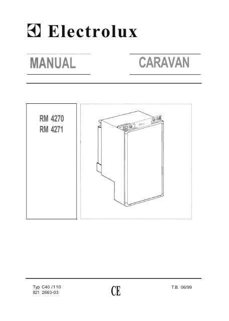
Electrolux<br />
CARAVAN<br />
RM 4270<br />
RM 4271<br />
Typ C40 /110<br />
CE<br />
T.B. 06/99<br />
821 2663-03
OPERATING AND INSTALLATION INSTRUCTIONS FOR<br />
ELECTROLUX REFRIGERATORS<br />
INTRODUCTION<br />
We are pleased that you have chosen this refrigerator and<br />
hope you will derive much satisfaction from using it, but first<br />
a few well-meant words of advice:<br />
It is important to read through these instructions carefully<br />
before using the refrigerator.<br />
To ensure good refrigeration and economical operation , the<br />
refrigerator must be installed and used as described in<br />
these instructions.<br />
The refrigerator is designed for building-in to leisure<br />
vehicles such as caravans or motorhomes.<br />
The appliance is certified according to the EU-Gas-Directive<br />
90/396/EEC.<br />
TRANSIT DAMAGE<br />
Inspect the refrigerator for damage. Transit damage must<br />
be reported to whoever is responsible for delivery not later<br />
than seven days after the refrigerator was delivered .<br />
DATA PLATE<br />
Check the data plate, inside the refrigerator, to ensure that<br />
you have received the right model.<br />
The right gas pressure is 30 mbar.<br />
The right voltage is 230 volts .<br />
The data plate contains e. g. the following details:<br />
Model designation RM .<br />
Product number<br />
Serial number<br />
Since these details will be needed if you have to contact<br />
service personnel, it is a good idea to make a note of them<br />
here.<br />
CONTENTS<br />
OPERATING INSTRUCTIONS<br />
CONTROLS<br />
STARTING THE REFRIGERATOR<br />
WINTER OPERATION<br />
REGULATING THE TEMPERATURE<br />
TRAVEL CATCH<br />
FOOD STORAGE<br />
ICE-MAKING<br />
DEFROSTING<br />
CLEANING THE REFRIGERATOR<br />
TURNING OFF THE REFRIGERATOR<br />
IF THE 'FRIDGE FAILS TO WORK<br />
MAINTENANCE<br />
SOME USEFUL HINTS<br />
GUARANTEE AND SERViCE<br />
TECHNICAL DATA<br />
INSTALLATION INSTRUCTIONS<br />
REPOSITIONING THE HINGES<br />
DOOR<br />
BUILDING-IN<br />
VENTILATION OF THE UNIT<br />
LP GAS CONNECTION<br />
ELECTRICAL CONNECTION<br />
8<br />
8<br />
8<br />
8<br />
8<br />
9<br />
9<br />
9<br />
9<br />
9<br />
9<br />
9<br />
10<br />
10<br />
10<br />
10<br />
10<br />
10<br />
10<br />
11<br />
11<br />
11<br />
12<br />
7
OPERATING INSTR UCTIONS<br />
CONTROLS<br />
The refrigerator can be run on either 230 V, 12 V or LP gas.<br />
Changing between these modes of operation is carried out<br />
by means of the controls of the control panel shown in fig 3.<br />
Two rocker switches are used to select the electric power<br />
supply, one for 230 V (B) and one for 12 V (A).<br />
Refrigerator temperature is controlled by a thermostat (C)<br />
when the unit runs on 230 V. The gas supply is turned<br />
on/off by means of the knob (0). When lighting the gas, one<br />
must press in the knob as explained further on.<br />
Refrigerator temperature is controlled by a thermostat (E)<br />
when the refrigerator runs on LP gas. Please note that the<br />
thermostat has no off" position.<br />
In model RM 4271 , the gas flame is electronically lit, monitored<br />
and relit if necessary. For this the toggle switch (F)<br />
should on" during gas operation.<br />
An indicator lamp in the switch flashes when the automatic<br />
igniter attempts to light the burner. Otherwise this lamp is<br />
off.<br />
In model RM 4270 a <strong>manual</strong> piezo-eletric igniter is used.<br />
When the button (G) is pressed, sparks are generated at<br />
the burner.<br />
Inside the refrigerator at bottom left is a sight glass for the<br />
burner. A blue light can be seen through it when the flame<br />
is alight. (RM 4270)<br />
STARTING THE REFRIGERATOR<br />
Caution!<br />
Only use one source of energy at a time<br />
The position numbers refer to fig . 3.<br />
LP Gas operation<br />
After initial installation, servicing, or changing gas cylinders<br />
etc., the gas pipes may contain some air which should be<br />
allowed to escape by briefly turning on the refrigerator or<br />
other appliances. This will ensure that the flame lights<br />
immediately.<br />
To start gas operation:<br />
1. Open the shut-off valve of the gas bottle (check that there<br />
is enough gas). Open anyon-board shut-off valve.<br />
2. Check that the switches for mains and 12 V operation are<br />
off.<br />
If you have Model RM 4271 proceed as follows:<br />
3. Turn on the gas supply by pressing the (0) knob and<br />
turning it to the position<br />
4. Set the thermostat knob (E) to the highest setting.<br />
5. Depress switch (F). A light in the switch should now start<br />
to flash, indicating that sparks are being generated at the<br />
burner.<br />
6. Press the (0) button. This opens the flame failure device<br />
and allows gas to flow to the burner.<br />
7. When the flame lights, the sparking stops automatically<br />
and the switch stops flashing.<br />
8. Keep the (0) button pressed for a further 10 to 15 seconds<br />
to active the flame failure device, then release it.<br />
If you have Model RM 4270 proceed as follows:<br />
3. Turn on the gas supply by pressing the (0) knob and<br />
turning it to the position<br />
4. Set the thermostat knob (E) to the highest setting.<br />
5. Keeping the flame failure device buttom (0) pressed,<br />
operate the igniter (G) until the flame lights.<br />
6. Keep the (0) buttom pressed for a further 10 to 15 seconds<br />
then release it.<br />
The flame can be observed in a wiewing glass inside the<br />
refrigerator at the bottom left (<strong>RM4270</strong>).<br />
To terminate gas operation, turn knob (0) to<br />
applicable) set switch (F) to<br />
and (when<br />
230 V Operation<br />
e Turn off gas or 12 V operation when applicable.<br />
e Turn the knob (C) of the thermostat to its highest (coldest)<br />
position.<br />
e Set switch (B) to position I. The switch will light up green<br />
when the power supply is connected.<br />
12 V Operation<br />
Only operate your refrigerator on 12 V when the engine of<br />
the vehicle is running - otherwise your battery will soon be<br />
discharged.<br />
e If applicable, turn off the gas operation.<br />
e Set the 12 V rocker switch (A) to I. The switch will light<br />
up red when the power supply is connected.<br />
WINTER OPERATION<br />
Please check th at the ventilation grilles or the flue outlet are<br />
not blocked by snow, leaves etc.<br />
ELECTROLUX ventilation grilles A 1620 (fig 2), can be<br />
fitted with winter covers, model WA 120, to protect the<br />
cooling unit against cold air. The covers may be fitted when<br />
the outside temperature is below approx. and should<br />
be fitted when the temperature is below the freezing point.<br />
We suggest that you fit the winter covers also in the case<br />
that the vehicle is laid up during the winter months.<br />
REGULATING THE TEMPERATURE<br />
The position number refers to fig . 3.<br />
It will take a few hours for the refrigerator to reach normal<br />
operating temperature. So we suggest you start it well in<br />
advance of a trip and if possible store it with precooled<br />
foodstuffs.<br />
On 230 V operation the refrigerator is controlled by a ther<br />
mostat and the thermostat knob (C) should be set at 3-5. If<br />
a lower (colder) temperature is desired, set the thermostat<br />
to a higher figure.<br />
On 12 V operation the refrigerator works continuously.<br />
On LP gas operation the refrigerator temperature is regula<br />
ted by the gas thermostat (E), which should be set at 3-5 If<br />
a lower (colder) temperature is desired, set the thermostat<br />
to a higher figure.<br />
8
TRAVEL CATCH<br />
Make sure that the travel catch is engaged when the caravan<br />
is on the move, (fig 1).<br />
The travel catch at the top of the door can be set in two<br />
different positions. In one position the door is held tightly<br />
shut. In the other position the door is secured ajar so that<br />
the refrigerator can be aired when not in use.<br />
FOOD STORAGE<br />
Always keep food in closed containers. Never put hot food<br />
in the refrigerator; allow it to cool first.<br />
Never keep items in the refrigerator which might give<br />
off flammable gases.<br />
The 2-star (**) frozen food compartment is intended for the<br />
storage of frozen food and for making ice. It is not suitable<br />
for freezing items of food.<br />
Never put bottles or cans of fizzy drinks in the frozen food<br />
storage compartment as they may burst when freezing. Also<br />
don't give children ice lollies straight from the frozen food as<br />
they could cause frost burns.<br />
Most kinds of frozen food can be stored in the frozen food<br />
compartment for about a month. This period of time may<br />
vary, however, and it is important to follow the instructions<br />
on the individual packets.<br />
ICE MAKING<br />
It is practical to make ice during the night - then the refrigerator<br />
is less demanded and the cooling unit has more reserves.<br />
Fill the ice tray to just below the brim with drinking<br />
water and place it on the freezer shelf.<br />
To speed up the ice making, one can spill one or two<br />
spoonfuls of water on the freezer shelf to improve the contact<br />
to the ice tray. If you have more than one ice tray it is a<br />
good idea to make ice in advance and save the frozen trays<br />
in the frozen food compartment.<br />
DEFROSTING<br />
Frost will gradually accumulate on the refrigerating surfaces.<br />
It must not be allowed to grow too thick as it acts as<br />
an insulator and adversely affects refrigerator perfor-mance.<br />
Check the formation of frost regularly every week and when<br />
it gets about 3 mm thick, defrost the refrigerator.<br />
To defrost the '<strong>fridge</strong> , turn it off and remove the ice tray and<br />
all food items. Warning: normally the temperature of items<br />
of fozen foods would rise unduly during defrosting and so<br />
they should be consumed within 24 h or discarded.<br />
Do not try to accelerate defrosting by using any kind of<br />
heating appliance, as this might damage the plastic surfaces<br />
of the refrigerator. Neither should any sharp objects<br />
be used to scrape off the ice.<br />
The defrost water runs from a collector channel to a receptacle<br />
at the rear of the refrigerator where it evaporates.<br />
Defrost water in the freezer compartment should be mopped<br />
up with a cloth.<br />
When the ice has melted, wipe the refrigerator dry and<br />
restart it. Place the food items back inside but wait until the<br />
refrigerator is cold before making ice cubes.<br />
CLEANING THE REFRIGERATOR<br />
Clean the inside of the refrigerator regularly to keep it fresh<br />
and hygienic.<br />
Soak a cloth in a solution consisting of a teaspoon of bicarbonate<br />
of soda to half a litre of warm water. Wring out the<br />
cloth and use it to clean the interior of the refrigerator and<br />
its fittings.<br />
Never use detergents, scouring powder, strongly scented<br />
products or wax polish to clean the interior of the refrigerator<br />
as they may damage the surfaces and leave a strong<br />
odour.<br />
The exterior of the refrigerator should be wiped clean now<br />
and again, using a damp cloth and a small quantity of detergent.<br />
But not the door gasket, which should only be cleaned<br />
with soap and water and then thoroughly dried.<br />
TURNING OFF THE REFRIGERATOR<br />
If the refrigerator is not to be used for some time:<br />
1. Set any switches to O.<br />
2. Set the gas valve (D) to •.<br />
3. Shut off anyon-board valve in the gas line to the refrigerator.<br />
4. Empty the refrigerator. Defrost and clean it as described<br />
earlier. Leave the doors of the refrigerator and the frozen<br />
food compartment ajar. Use the travel catch to hold in<br />
this position.<br />
5. When the vehicle is laid up for a long period of time<br />
(e.g . during the winter months), we suggest fitting the<br />
winter covers WA 120, fig. 2, onto the vent grills.<br />
IF<br />
FRIDGE FAILS TO WORK<br />
Check the following points before calling a service<br />
technician:<br />
1. That the STARTING THE REFRIGERATOR instructions<br />
have been followed.<br />
2. The refrigerator is level.<br />
3. If it is possible to start the refrigerator on any of the<br />
connected sources of energy.<br />
4. If the refrigerator fails to work on gas, check:<br />
• That the gas bottle is not empty.<br />
• That all Lp-gas valves are open.<br />
5. If the refrigerator fails to work on 12 V, check:<br />
• That the 12 V supply is connected to the refrigerator.<br />
• That the fuse on the 12 V supply is intact.<br />
• That the 12 V switch is on.<br />
6. If the refrigerator fails to work on 230 V, check:<br />
• That the 230 V supply is connected to the refrigerator.<br />
• That the fuse is intact.<br />
If the refrigerator is not cold enough it may be because:<br />
1. The ventilation is inadequate owing to reduced area of<br />
the ventilation passages (partial blockage of grilles from<br />
wire mesh etc).<br />
9
2. The evaporator is frosted up.<br />
3. The temperature control setting is incorrect.<br />
4. The gas pressure is incorrect check the pressure regulator<br />
at the gas container.<br />
5. The ambient temperature is too high.<br />
6. To much food is loaded at one time.<br />
7 . The door is not properly closed or the magnetic sealing<br />
strip is defective.<br />
8. More than one source of energy is used at the same<br />
time. If the refrigerator still does not work properly, call a<br />
service technician .<br />
The sealed cooling system must not be opened, since<br />
it is under high pressure.<br />
MAINTENANCE<br />
Concerning gas- and electric installations, only authorized<br />
experts are allowed to carry out maintenance and repair<br />
works. Besides, it is recommendable to contact an authorized<br />
service if it comes to repair works.<br />
According to the valid regulations G607 of DVGW, the gas<br />
installation as well as the connect flue oulets are to be<br />
checked every two years by an expert (this has to be<br />
arranged by the person responsible).<br />
SOME USEFUL HINTS<br />
Make sure that:<br />
• The refrigerator is not operating on 12 V when the vehicle<br />
is parked, otherwise you will drain the car battery in<br />
a short time.<br />
• Defrosting is carried out periodically.<br />
• The refrigerator is left with the door(s) ajar when it is not<br />
to be used for some time.<br />
• Liquids or items with a strong odour are well packaged.<br />
• The ventilation openings are unobstructed.<br />
• The door is secured by means of the travel catch when<br />
the caravan is on the move.<br />
• Only one mode of operation at a time is used to run the<br />
refrigerator.<br />
GUARANTEE AND SERVICE<br />
The refrigerator is guaranteed for one full year on condition<br />
that it is used in a correct manner and in accordance with<br />
these operating and installation instructions.<br />
It is also embraced by a European guarantee as described<br />
in the brochure supplied with the refrigerator.<br />
Service and spare sparts are obtainable from your dealer or<br />
Electrolux - consult the telephone directory<br />
TECHNICAL DATA RM 4270/71<br />
Overall dimensions, refrigerator<br />
Height . . . . . . . . . . . . .821 mm<br />
Width . . . . . . . . . . . . . . . . . . . .486 mm<br />
Depth (inc!. cooling unit)<br />
without door<br />
with door<br />
.495 mm<br />
534 mm<br />
Build-in dimensions<br />
Height 825 mm<br />
Width . . . . . . . . . . . . . . . .490 mm<br />
Depth 505 mm<br />
Step (wheel house)<br />
Height<br />
max 220 mm<br />
Width. . . . . . . . . . . . . ... 490 mm<br />
Depth<br />
max 225 mm<br />
Capacity<br />
gross 77 lit.<br />
net 72 lit.<br />
frozen food compt 7 lit.<br />
Weight (without packaging) 23 kg<br />
Electrical data<br />
Input 230 V<br />
125 watt<br />
12 V. .. 120 watt<br />
Energy consumption /24 h 2,5 kWh<br />
LP gas data<br />
Input<br />
232 watt<br />
ditto, low flame. . . . . . .<br />
105 watt<br />
Energy consumption /24 h 0,27 kg<br />
Cooling medium Ammonia (R 717)<br />
INSTALLATION INSTRUCTIONS<br />
REPOSITIONING THE HINGES<br />
The door hinges can be moved to the opposite side in the<br />
following way:<br />
• Unscrew the upper hinge pin, taking care not to lose the<br />
set of washers and bushes.<br />
• Lift the door from the lower hinge pin.<br />
• Unscrew the pin and mount it on the opposite side hinge.<br />
• Unscrew the travel catch and mount it on the opposite<br />
side.<br />
• On the upper edge of the door are two plastic inserts for<br />
the alternative holes of the travel catch. Pry out carefully<br />
and exchange<br />
• Fit the door on the pin and reassemble the pin with<br />
washers and bushes in its new place.<br />
• Check that the door closes properly and seals all round.<br />
DOOR PANEL<br />
The door panel can easily be mounted or changed. The<br />
dimensions of the panel must be:<br />
Height<br />
Width<br />
Thickness<br />
740 mm<br />
453 ,5 mm<br />
max 3,8 mm<br />
• Remove the door, see REPOSITIONING THE HINGES.<br />
10
• Remove the lower trim moulding and then withdraw the<br />
panel by sliding it downwards.<br />
• Fit new panel in place and slide it up as far as possible.<br />
• Fit the trim moulding back in place.<br />
BUILDING-IN<br />
The refrigerator is intended for installation in a caravan or<br />
motorhome, and the description relates to this application.<br />
The refrigerator must not be exposed to radiated heat from<br />
hot objects (e.g. below a cooker without proper heat shielding).<br />
Excessive heat irradiation impairs performance and leads to<br />
increased energy consumption. For this reason the refrigerator<br />
should be installed if possible not at the entrance side<br />
of the vehicle - normally orientated south and often with an<br />
awning - which would impair the dispersion of heat and<br />
combustion gases from the ventilation openings.<br />
It is not a good practice to install the refrigerator so that the<br />
vent openings are covered by the vehicle's entrance door<br />
when this is open. Thi s would reduce the ventilation air fl ow<br />
to the cooling unit and reduce refrigeration performance.<br />
The enclosure<br />
The refrigerator must be installed in an enclosure, the<br />
dimensions of which are shown in TECHNICAL DATA.<br />
The bottom of the enclosure must be horizontal and even<br />
so that the refrigerator can be easily pushed into place. It<br />
must be sturdy enough to carry the wieght of the refrigerator.<br />
Battens must be installed at the enclosure and fitted with<br />
sealing strips, as shown in fig . 4.<br />
Slide in the refrigerator until it is flush with the front of the<br />
recess. There must be 10-20 mm free space behind the<br />
refrigerator.<br />
Four fasteners are fitted in plastic bushings in the side walls<br />
of the <strong>fridge</strong>, fig . 7. They are used for securing the refrigerator<br />
in the enclosure.<br />
The side walls of the enclosure and/or any wooden braces<br />
installed to hold the refrigerator must be dimensioned to<br />
seat the screws securely, also considering the forces due to<br />
the movement of the vehicle.<br />
With the refrigerator in place, drive the screws through the<br />
bushings in the lining of the refrigerator into the walls of the<br />
enclosure (fig.7). There must not be more than 3mm of<br />
clearance between refrigerator and enclosure on each side.<br />
If necessary, wooden strips or similar should be fitted.<br />
Note: This is the only approved means of securing the<br />
refrigerator to the enclosure and to the vehicle. Fasteners<br />
penetrating other parts of the insulation (PU) foam of the<br />
refrigerator might damage components like electric wiring<br />
etc.<br />
VENTILATION OF THE UNIT<br />
At high ambient temperatures the refrigeration unit will only<br />
perform adequately when properly ventilated.<br />
The refrigeration unit is ventilated via two openings in the<br />
wall of the caravan (see fig. 5). Fresh air enters through the<br />
lower opening and warm air is discharged through the upper<br />
one.<br />
Locate the lower opening immediately above the floor of the<br />
recess, and the upper one as high as possible above the<br />
condenser (C) of the refrigeration unit, at least as shown in<br />
fig. 6b but preferably as shown in fig. 6a.<br />
Ventilation grilles Fig. 2<br />
The openings in the caravan wall must be fitted with the<br />
Electrolux ventilation systems.<br />
Fitting the grilles, model A 1620, which were specially<br />
developed by Electrolux for this purpose (shown as D in fig.<br />
6). It is a good idea, to install the frame R 1640 (A in the<br />
same figure), at the same time. Then the grilles can be<br />
easily removed which permits inspection and small repairs<br />
to be carried out without the necessity for removing the<br />
refrigerator from the recess.<br />
If there is no outer grille at floor level where leaking gas can<br />
escape, a 40 mm hole to the outside should be made in the<br />
floor of the recess to drain any unburnt gas to the outside<br />
gas.<br />
Fit the hole with wire mesh and an angled plate to protect<br />
from stones, mud etc.<br />
Removal of flue gases<br />
The ventilation passage at the rear of the recess, between<br />
the outer wall of the vehicle and the refrigerator (fig. 6) , is<br />
sealed off against the living space, and so cold draughts are<br />
excluded (winter camping) and no flue gases can penetrate<br />
into the vehicle. Thus a special flue outlet is no longer<br />
necessary - the gases are dispersed through the upper vent<br />
grille.<br />
Note: With this mode of installation the same type of grilles<br />
(without an integrated flue outlet), should be installed at the<br />
upper as well as at the lower vent open-ning. The angled<br />
T-piece for the flue tube (when delivered) should not be<br />
used in this case.<br />
The top of the enclosure above the flue tube (I), fig 6,<br />
should be covered with aluminum sheet metal, as indicated<br />
in (B), to facilitate the heat dispersion.<br />
In fig . 6 the letters have the following meaning:<br />
A. Frame R 1640 for the grilles<br />
B. Aluminum cladding<br />
C. Condenser of cooling unit<br />
D. Vent grill A 1620<br />
E. Sealing profile (optional extra)<br />
Width 486 mm , Electrolux art. nr. 295 1147-10<br />
F. Refrigerator rear wall<br />
G. Wooden batten approx. 10 x 20 mm (see fig . 4)<br />
H. Height of the enclosure (see TECHNICAL DATA)<br />
I. Flue tube<br />
LP GAS CON NECTION<br />
CAUTION! CHECK THAT THE GAS SUPPLIED TO<br />
THE REFRIGERATOR IS AT THE CORRECT<br />
PRESSURE. SEE THE REDUCING VALVE ON THE<br />
LP GAS CONTAINER<br />
The refngerator IS designed for operation on LP gas of<br />
Butane type the pressure of which must be 28 mbar for<br />
Butane and 37 mbar for Propane.<br />
11
Check that this is stated on the data plate. The refrigerator<br />
is not designed for operation on town gas or natural gas.<br />
The gas installation should only be carried out by an<br />
authorized gas fitter.<br />
The supply pipe should preferably be of copper. If any other<br />
material is used, it must be of a type approved for use with<br />
continuously operating bottled- gas appliances, and have<br />
th readed compression connections th roughout. PUSH-ON<br />
CONNECTIONS MUST NOT BE USED (We do not approve<br />
the use of ., rubber" type flexible tubing for connecting<br />
permanently operating appliances of this type in the United<br />
Kingdom). All connectors etc. should be of a type specifically<br />
designed for the type and diameter of the connection pipe<br />
used, and screwed joints should be sealed with a joining<br />
compound approved for use wi th bottled gas.<br />
The gas supply pipe should be connected to the gas inlet<br />
pipe on the right hand side of the gas control valve by<br />
means of a suitable th readed compression coupling.<br />
In making the connection to the refrigerator, a gas cock of<br />
an approved type for use on LPG must be incorporated in<br />
the supply line in a position which is readily accessible to<br />
the user. For eventual servicing purposes, the union should<br />
be on the outlet side of the cock and the pipework should<br />
be positioned so as not to prevent the refrig erator from<br />
being readily withdrawn.<br />
ELECTRICAL CONNECTION<br />
The electrical installation must be carried out in a proper<br />
and durable manner, taking into account all relevant regulations<br />
and codes of practice. For mains voltage operation, it<br />
is important that the circuit to and in the caravan is effectively<br />
earthed. A LL MAINS VOLTAGE WIRING IN THE<br />
CARA-VAN MUST BE INSTALLED IN ACCORDANCE<br />
WITH CURRENT REGULATIONS INCLUDING THE<br />
USE OF AN OUTLET AND COUPLER TO BS4343/<br />
CEE17.<br />
For connection to a 230 V electricity supply, the refrigerator<br />
has a 3-core mains lead which is intended for connection to<br />
a properly earthed plug and socket outlet or fused spur.<br />
IMPORTANT: The wires in the mains lead of this appliance<br />
are coloured in accordance with the following code:<br />
GREEN-AND-YELLOW = EARTH<br />
BLUE = NEUTRAL<br />
BROWN = LIVE<br />
As the colours of the wires may not correspond with the<br />
coloured markings identifying the terminals in your plug, in<br />
the United Kingdom, proceed as follows:<br />
The wire which is coloured GREEN-AND-YELLOW must be<br />
connected to the terminal in the plug which is marked with<br />
the letter E or by the earth symbol -=- or coloured green or<br />
green-and-yellow.<br />
The wire which is coloured BLUE must be connected to the<br />
terminal which is marked with the letter N or coloured black.<br />
The wire which is coloured BROWN must be connected to<br />
the terminal which is marked with the letter L or co loured<br />
red.<br />
3 amp. fuse. In other countries, the fuse rating will depend<br />
upon the voltage and local practice.<br />
230 V Supplies.<br />
Check that the voltage stated on the data plate is the same<br />
as the mains voltage in use (230 V) .<br />
Electrical leads must be routed and secured so that<br />
t hey cannot come into contact wit h hot or sharp parts<br />
of the refrigerator.<br />
12 V Supplies<br />
Connect the refrigerator to the vehicle battery by a direct<br />
cable. To avoid a voltage drop, the cross sectional area of<br />
the connecting cable between battery and refrigerator must<br />
be at least 2.5 mm 2 if the distance is less than 9 meters,<br />
and at least 4 mm 2 if the distance is more than 9 meters<br />
To ensure satisfactory operation, the positive lead must be<br />
fitted with a fuse rated at max. 16 A.<br />
To prevent the refrigerator from draining the battery, make<br />
sure that the current supplied to the caravan is cut off when<br />
the vehicle engine is not running, for example by fitting an<br />
ignition control relay.<br />
Diagramme for the mains installation: fig. 9<br />
Diagramme for the 12 V installation:<br />
fig . 10 (RM 4270), fig. 12 (RM 4271 )<br />
The notations in the wiring diagramme are:<br />
A. Electronic igniter/reigniter<br />
B. Electrode (at burner)<br />
C. 12 V heating element<br />
D. Switch for 12 V operation<br />
E. Switch for reigniter (gas op.)<br />
F. Electric thermostat<br />
G. Heating element, 230 V<br />
H. Switch for 230 V operation<br />
J. Terminal block<br />
L. Terminal block<br />
12 V supply of reigniter (RM 4271)<br />
Fig. 12 shows the wiring diagramme of the refrigerator as<br />
delivered. The 12 V supply enters at (L). The reigniter (A) is<br />
fed via two wires (1) and (2) at terminal block (L).<br />
It is advisable to feed the reigniter and the lighting from a<br />
separate 12 V source. To do this: remove the wires (1) and<br />
(2) and connect the supply as is shown in fig. 11 .<br />
In some executions there in an extra terminal block (J) , of<br />
fig . 12. In this case one disconnects the wires as said above<br />
but connects the separate supply to (J).<br />
The reign iter should not be connected directly to a battery<br />
charger but only over a battery.<br />
WARNING! THIS APPLIANCE MUST BE EARTHED!<br />
In the United Kingdom, the plug or circuit to the refrigerator<br />
must be fitted with a fuse not greater than 5 amps. If a 13<br />
amp.(B.S.1363) fused plug is used, it should be fitted with a<br />
12