Challenges of Welding Aluminium Alloys for Automotive ... - Esab
Challenges of Welding Aluminium Alloys for Automotive ... - Esab
Challenges of Welding Aluminium Alloys for Automotive ... - Esab

You also want an ePaper? Increase the reach of your titles
YUMPU automatically turns print PDFs into web optimized ePapers that Google loves.
<strong>Challenges</strong> <strong>of</strong> <strong>Welding</strong><strong>Aluminium</strong><br />
<strong>Alloys</strong> <strong>for</strong> <strong>Automotive</strong> Structures<br />
by J.F. Hinrichs, J.S. Noruk, WM. McDonald, and R.J. Heideman<br />
In response to the need <strong>for</strong> lighter structures, the use <strong>of</strong> aluminium alloys in transportation<br />
vehicles has increased. By reducing weight, vehicle fuel consumption and<br />
engine emissions are reduced.<br />
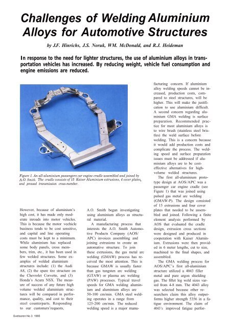
Figure 1. An all-aluminium passengers car engine cradle assembled and joined by<br />
A.O. Smith. The cradle consists <strong>of</strong> 155Kaiser <strong>Aluminium</strong> extrusions, 4 cover plates,<br />
and pressed transmission cross-member.<br />
However, because <strong>of</strong> aluminium’s<br />
high cost, it has made only moderate<br />
inroads into motor vehicles.<br />
This is because the motor vechicle<br />
business tends to be cost sensitive,<br />
and capital and line operating<br />
costs must be kept to a minimum.<br />
While aluminium has replaced<br />
some body panels, cross members,<br />
trim, etc., it has been used in<br />
few welded structures. Some examples<br />
<strong>of</strong> welded aluminium<br />
structures include: (1) the Audi<br />
A8, (2) the spare tire structure on<br />
the Chevrolet Corvette, and (3)<br />
Honda’s Acura NSX. The measure<br />
<strong>of</strong> success <strong>of</strong> any future high<br />
volume welded aluminium structures<br />
will be compared in per<strong>for</strong>mance,<br />
quality, and cost to their<br />
steel counterparts. Responding<br />
to our customers’requests,<br />
A.O. Smith began investigating<br />
using aluminium alloys as structural<br />
material.<br />
A manufacturing process that<br />
interests the A.O. Smith <strong>Automotive</strong><br />
Products Company (AOS/<br />
APC) invoices assembling and<br />
joining extrusions to create an<br />
automative structure. To join<br />
these extrusions, the gas metal arc<br />
welding (GMAW) process has received<br />
the most attention. This is<br />
because GMAW is usually faster<br />
than gas tungsten arc welding<br />
(GTAW) or plasma arc welding<br />
(PAW) processes. Typical travel<br />
speeds <strong>for</strong> GMA welding aluminium<br />
and aluminium alloys are<br />
50-100 cm/min. GMA steel welding<br />
operates in a range from<br />
125-200 cm/min. The reduced<br />
welding speed is a major manufacturing<br />
concern. If aluminium<br />
alloy welding speeds cannot be increased,<br />
production costs, compared<br />
to steel structures, will be<br />
higher. This will make the justification<br />
to use aluminium difficult.<br />
A second concern regarding aluminium<br />
GMA welding is surface<br />
preparation. Recommended practice<br />
<strong>for</strong> most aluminium alloys is<br />
to wire brush (stainless steel bristles)<br />
the weld surface be<strong>for</strong>e<br />
welding. This is a concern because<br />
it would add production costs and<br />
complicate the process. The welding<br />
speed and surface preparation<br />
issues must be addressed if aluminium<br />
alloys are to be costeffective<br />
alternatives <strong>for</strong> highvolume<br />
welded structures.<br />
The first all-aluminium prototype<br />
design at AOS/APC was a<br />
passenger car engine cradle (see<br />
Figure 1) that was joined using<br />
pulsed gas metal arc welding<br />
(GMAW-P). The design consisted<br />
<strong>of</strong> 15 extrusions and four cover<br />
plates that needed to be assembled<br />
and joined. Following a finite<br />
element analysis per<strong>for</strong>med by<br />
AOS that evaluated the cradle<br />
design, extrusion cross sections<br />
were designed and produced in<br />
cooperation with Kaiser <strong>Aluminium</strong>.<br />
Extrusions were then provided<br />
in 6 meter lengths, cut to size,<br />
machined to the final shapes, and<br />
assembled.<br />
The GMA welding process <strong>for</strong><br />
AOS/APC’s first all-aluminium<br />
structure utilized a 4043 filler<br />
metal and pure argon shielding<br />
gas. The fillet leg weld sizes varied<br />
from 4-8 mm. The 4043 alloy<br />
was selected because other researchers<br />
claim this alloy outper<strong>for</strong>ms<br />
higher strength 5356 in a fatigue<br />
environment. The claim <strong>of</strong><br />
4043’s improved fatigue per<strong>for</strong>-<br />
Svetsaren No 3 1995
The welding cell used to join extrusions <strong>for</strong> an all-aluminium passenger car engine cradle. The cell contains an ABB<br />
IRB2400 robot, an ESAB Digipulse 4SOi power source, and a Binzel WH455 welding torch.<br />
mance is the subject <strong>of</strong> another<br />
investigation at AOS/APC.<br />
The welding cell used to assemble<br />
the prototype cradles contained<br />
an ABB IRB2400 robot<br />
that was equipped with an ESAB<br />
Digipulse 4SOi power source and<br />
a Binzel WH455 welding torch<br />
(see Figure 2). The ESAB Digipulse<br />
450i power source was specifically<br />
tuned by ESAB <strong>for</strong> welding<br />
aluminium alloys. To minimize<br />
wire feeding problems. a 10<br />
kg wire spool was mounted on the<br />
robot. 1 m from the welding<br />
torch. This minimized the push<br />
distance and simplified wire feeding.<br />
While this setup was acceptable<br />
<strong>for</strong> the prototype builds, it<br />
would not be a good manufacturing<br />
option because replacing<br />
small spools would create excessive<br />
downtime.<br />
To reduce downtime in a manufacturing<br />
environment, a minimum<br />
100 kg spool would be<br />
mounted next to the robot. The<br />
increased wire feeding distance<br />
resulting from this setup could<br />
cause problems; however, to overcome<br />
these, a push-pull welding<br />
torch would most likely be used.<br />
On a robotic push/pull torch. the<br />
drive rolls (pushing) are mounted<br />
on the robot, closer to the wire<br />
spool. The pulling or helper drive<br />
roll is mounted on the torch very<br />
close to the contact tube. A pulling<br />
drive roll keeps the weld wire<br />
tight (no slack) during welding<br />
and complex robot moves and<br />
maximizes weld starts.<br />
Along with the 49 GMAW<br />
welds on the prototype cradles,<br />
there were two welds that used<br />
the friction stir welding process.<br />
Friction stir welding is patented<br />
by TWI and appears to have<br />
promise in joining structural components.<br />
By welding below the<br />
melting point <strong>of</strong> aluminium alloys,<br />
heat input is reduced. This<br />
leads to less distortion. smaller<br />
weld grain size. narrower heat atfectcd<br />
zone (HAZ). and properties<br />
closer to the base metal. In<br />
addition. the weld pr<strong>of</strong>ile is nearly<br />
flat which could improve fatigue<br />
per<strong>for</strong>mance. Finally, friction stir<br />
welding <strong>of</strong> 6xxx series alloys requires<br />
no surface preparation.<br />
Friction stir welding was used to<br />
make two full penetration and<br />
autogeneous 8 mm but welds. The<br />
friction stir welds were made by<br />
ESAB AB in Laxå Sweden without<br />
surface preparation at about<br />
20 cm/min. The friction stir welds<br />
replaced 4 pass GMA welds. Figure<br />
3 shows macro structures <strong>of</strong> a<br />
GMAW sample compared to a<br />
friction stir welded sample.<br />
After AOS gained experience<br />
welding prototype cradles and<br />
talked to non-automotive aluminium<br />
fabricators, we concluded<br />
that the key to successfully GMA<br />
welding aluminium alloys is a eld<br />
8
Acknowledgements:<br />
We wish to acknowledge the Valuable<br />
contributions made by many<br />
colleagues within A.O. Smith. at<br />
<strong>Esab</strong> AB in Laxå Sweden, and<br />
The <strong>Esab</strong> Group in the USA.<br />
Figure 3. Cross-sections showing the macrostructures <strong>of</strong> two welds: (a) friction stir<br />
weld and (b) 4pass GMAW welds made with 4043 filter metal.<br />
Reference:<br />
(1) D.R. White and J.E. Jones, Gas Metal<br />
Arc <strong>Welding</strong> <strong>of</strong> Thin Section <strong>Aluminium</strong><br />
with Dissimilar <strong>Alloys</strong>. Presented at 1995<br />
AWS Convcntion in Clevcland, OH.<br />
filler metal feeding. <strong>Aluminium</strong><br />
alloys being s<strong>of</strong>ter than steel tend<br />
to score easily. When the weld filler<br />
metal scores, it produces fine<br />
aluminium particles (we’ll refer to<br />
these as flakes). These flakes are<br />
then deposited in the wire liner or<br />
entrance <strong>of</strong> the contact tube, constricting<br />
filler metal feeding and<br />
causing bum-backs.<br />
To compensate <strong>for</strong> the flaking<br />
problem. other fabricators report<br />
using oversized contact tubes and<br />
liners. This increases mean-time<br />
between failures by allowing<br />
more flakes to accumulate in the<br />
filler metal feed system be<strong>for</strong>e becoming<br />
detrimental. In noncritical<br />
weldments, oversized contact<br />
tubes may be an acceptable<br />
solution. However, using oversized<br />
contact tubes in robotically<br />
welded. fatigue-sensitive structures.<br />
could cause misalignment<br />
<strong>of</strong> the wire in the joint. Wire misalignment<br />
can lead to root penetration<br />
problems which could lead<br />
to premature failure. In addition,<br />
oversized contact tubes can cause<br />
inconsistent current pickup resulting<br />
in poor starts and burn-backs.<br />
The filler metal misalignment<br />
concern with oversized contact<br />
tubes becomes more serious when<br />
welding different fillet leg sizes.<br />
For instance. welding a lap fillet<br />
with two plates <strong>of</strong> equal thicknesses<br />
in the flat positions<br />
presents few problems. However.<br />
when two plates <strong>of</strong> unequal thicknesses<br />
are welded togcthcr, fillet<br />
leg penetration becomes sensitive<br />
to wire position. If the wire moves<br />
in the joint, which is more likely<br />
with oversized contact tubes, controlling<br />
fillet leg penetration<br />
~ could be more difficult.<br />
While using oversized contact<br />
tubes is effective, we have not<br />
pursued this solution because <strong>of</strong><br />
the filler metal alignment concern.<br />
Rather, we have focused on<br />
reducing weld filler metal score.<br />
Our observations showed that the<br />
contact tube entrance was a significant<br />
area <strong>for</strong> aluminium flakes<br />
and slivers to buildup. By deburring<br />
the contact tube’s entrance,<br />
we were able to increase its life<br />
and improve arc stability and per<strong>for</strong>mance.<br />
In the initial demonstration<br />
cradles built by AOS. welding<br />
speeds were about 75-90 cm/min.<br />
much below the 150 cm/min. common<br />
in similar steel structures.<br />
Research ef<strong>for</strong>ts were reported at<br />
the 1995 AWS International Expositions<br />
and Conference in<br />
Cleveland, OH, where aluminium<br />
weld schedules that travel 250<br />
cm/min. and achieve high quality<br />
welds without any surface preparation<br />
were being developed. This<br />
work concentrated on 1-3 mm<br />
stock thicknesses and used Neural<br />
Nets to develop the initial weld<br />
schedules. These speeds along<br />
with no surface preparation are<br />
attractive <strong>for</strong> high-volume manufacturing.<br />
(1)<br />
<strong>Welding</strong> <strong>of</strong> aluminium alloys is<br />
not new, but many process improvements<br />
arc needed to make<br />
aluminium welding in a highvolume<br />
automotive manufacturing<br />
environment practical. To<br />
make aluminium an economical<br />
choice <strong>for</strong> motor vehicle manufacturers,<br />
are welding must be automated,<br />
friction stir welding technology<br />
exploited, welding speeds<br />
incrcascd. equipment up-time incrcascd,<br />
and surface preparation<br />
eliminated. These will be our<br />
challenges as we try to make aluminium<br />
structures a viable option<br />
<strong>for</strong> our customers.<br />
About the authors:<br />
John F. Hinrichs holds a B.S. Degree<br />
in Mechanical Engineering<br />
and a M.S. Degree in Metallurgical<br />
Engineering. He has been employed<br />
by A.O. Smith <strong>for</strong> 40 years<br />
and is currently an Engineermg<br />
Fellow at the A.O. Smith Corporate<br />
Technology Center. He has<br />
held many positions within the<br />
A.O. Smith <strong>Automotive</strong> Products<br />
Company including Director <strong>of</strong><br />
Manufacturing Engineering. He<br />
also serves on many AWS committees,<br />
is an AWS Fellow, and recipient<br />
<strong>of</strong> the 1989 Golden Robot<br />
Award.<br />
Jeff S. Noruk holds a B.S. Degree<br />
in <strong>Welding</strong> Engineering and a<br />
M.S. Degree in Engineering Management.<br />
Hc has been employed<br />
by the A.O. Smith <strong>Automotive</strong><br />
Products Company <strong>for</strong> 10 years<br />
and is currently the Manager <strong>of</strong><br />
<strong>Welding</strong>, Robotics and Controls in<br />
the Advanced Product and Process<br />
Technology Group. Prior to<br />
A.O. Smith, Jeff was employed as<br />
a welding engineer by the Harnischfeger<br />
Corp. and Newport<br />
News Shipbuilding and was the<br />
Manager <strong>of</strong> Material Joining at<br />
FANUC Robotics.<br />
William M. McDonald holds<br />
A.A.S. Dcgrces in <strong>Welding</strong> Technology<br />
and Metallurgical Technology.<br />
He has been employed by the<br />
A.O. Smith <strong>Automotive</strong> Products<br />
Company <strong>for</strong> 12 years and is currently<br />
a <strong>Welding</strong> Technician II <strong>for</strong><br />
the Advanced Process and Product<br />
Technology Group. Prior to<br />
A.O. Smith, Bill worked as a<br />
welding supervisor <strong>for</strong> the Ladish<br />
Company and was a Gun Fire Petty<br />
Officer First Class in the U.S.<br />
Navy.<br />
Robert J. Heideman holds B.S.<br />
and M.S. Degrees in Metallurgical<br />
Engineering and has been employed<br />
at the A.O. Smith Corporate<br />
Technology Center since 1994<br />
as a project engineer. Prior to<br />
A.O. Smith, he worked as a process<br />
engineer <strong>for</strong> Delco Electronics.