Workbench Mechanical - Introduction to Contact
Workbench Mechanical - Introduction to Contact
Workbench Mechanical - Introduction to Contact

You also want an ePaper? Increase the reach of your titles
YUMPU automatically turns print PDFs into web optimized ePapers that Google loves.
Chapter 3<br />
<strong>Introduction</strong> <strong>to</strong> <strong>Contact</strong><br />
<strong>Workbench</strong> - <strong>Mechanical</strong><br />
Structural Nonlinearities<br />
ANSYS, Inc. Proprietary<br />
© 2009 ANSYS, Inc. All rights reserved.<br />
3-1<br />
April 30, 2009<br />
Inven<strong>to</strong>ry #002659
<strong>Workbench</strong> <strong>Mechanical</strong> - <strong>Introduction</strong> <strong>to</strong> <strong>Contact</strong><br />
Chapter Overview<br />
Training Manual<br />
• An introduction <strong>to</strong> solid body contact will be presented in<br />
this chapter:<br />
– It is assumed that the user has already covered Chapter 2<br />
Nonlinear Structural prior <strong>to</strong> this chapter.<br />
• The Specific <strong>to</strong>pics introduced are:<br />
A. Basic concept of contact<br />
B. <strong>Contact</strong> Formulations<br />
C. Stiffness and Penetration<br />
D. Workshop 3A<br />
E. Pinball Region<br />
F. Symmetric vs. Asymmetric<br />
G. Postprocessing <strong>Contact</strong> Results<br />
H. Workshop 3B<br />
• The capabilities described in this Chapter are generally<br />
applicable <strong>to</strong> ANSYS Structural licenses and above.<br />
ANSYS, Inc. Proprietary<br />
© 2009 ANSYS, Inc. All rights reserved.<br />
3-2<br />
April 30, 2009<br />
Inven<strong>to</strong>ry #002659
<strong>Workbench</strong> <strong>Mechanical</strong> - <strong>Introduction</strong> <strong>to</strong> <strong>Contact</strong><br />
A. Basic Concepts<br />
Training Manual<br />
<strong>Contact</strong>:<br />
• When two separate surfaces <strong>to</strong>uch each other such that they become<br />
mutually tangent, they are said <strong>to</strong> be in contact.<br />
• In the common physical sense, surfaces that are in contact have<br />
these characteristics:<br />
– They do not interpenetrate.<br />
– They can transmit compressive normal forces and tangential friction<br />
forces.<br />
– They often do not transmit tensile normal forces.<br />
• They are therefore free <strong>to</strong> separate and move away from each other.<br />
• <strong>Contact</strong> is a changing-status nonlinearity. That is, the stiffness of the<br />
system depends on the contact status, whether parts are <strong>to</strong>uching or<br />
separated.<br />
ANSYS, Inc. Proprietary<br />
© 2009 ANSYS, Inc. All rights reserved.<br />
3-3<br />
April 30, 2009<br />
Inven<strong>to</strong>ry #002659
<strong>Workbench</strong> <strong>Mechanical</strong> - <strong>Introduction</strong> <strong>to</strong> <strong>Contact</strong><br />
... Basic Concepts<br />
Training Manual<br />
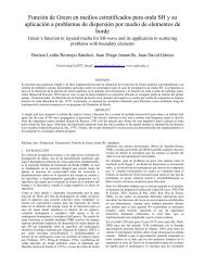
How compatibility is enforced in a contact region:<br />
• Physical contacting bodies do not interpenetrate. Therefore, the<br />
program must establish a relationship between the two surfaces <strong>to</strong><br />
prevent them from passing through each other in the analysis.<br />
– When the program prevents interpenetration, we say that it enforces<br />
contact compatibility.<br />
– <strong>Workbench</strong> <strong>Mechanical</strong> offers several different contact formulations <strong>to</strong><br />
enforce compatibility at the contact interface.<br />
F<br />
Penetration occurs when contact<br />
compatibility is not enforced.<br />
<strong>Contact</strong><br />
Target<br />
F<br />
ANSYS, Inc. Proprietary<br />
© 2009 ANSYS, Inc. All rights reserved.<br />
3-4<br />
April 30, 2009<br />
Inven<strong>to</strong>ry #002659
<strong>Workbench</strong> <strong>Mechanical</strong> - <strong>Introduction</strong> <strong>to</strong> <strong>Contact</strong><br />
B. <strong>Contact</strong> Formulations<br />
• For nonlinear solid body contact of faces, Pure Penalty or<br />
Augmented Lagrange formulations can be used:<br />
– Both of these are penalty-based contact formulations:<br />
F = k<br />
normal normal penetration<br />
Here, for a finite contact force F normal , there is a concept of contact<br />
stiffness k normal . The higher the contact stiffness, the lower the<br />
penetration x penetration , as shown in the figure below<br />
x<br />
Training Manual<br />
– Ideally, for an infinite k normal , one would get zero penetration. This is not<br />
numerically possible with penalty-based methods, but as long as<br />
x penetration is small or negligible, the solution results will be accurate.<br />
F n<br />
x p<br />
ANSYS, Inc. Proprietary<br />
© 2009 ANSYS, Inc. All rights reserved.<br />
3-5<br />
April 30, 2009<br />
Inven<strong>to</strong>ry #002659
<strong>Workbench</strong> <strong>Mechanical</strong> - <strong>Introduction</strong> <strong>to</strong> <strong>Contact</strong><br />
... <strong>Contact</strong> Formulations<br />
Training Manual<br />
• The main difference between Pure Penalty and Augmented Lagrange<br />
methods is that the latter augments the contact force (pressure)<br />
calculations:<br />
Pure Penalty:<br />
Augmented Lagrange:<br />
F = k<br />
F<br />
normal<br />
normal<br />
normal<br />
x<br />
penetration<br />
= knormal<br />
x<br />
penetratio n<br />
+ λ<br />
• Because of the extra term λ, the augmented Lagrange method is less<br />
sensitive <strong>to</strong> the magnitude of the contact stiffness k normal .<br />
ANSYS, Inc. Proprietary<br />
© 2009 ANSYS, Inc. All rights reserved.<br />
3-6<br />
April 30, 2009<br />
Inven<strong>to</strong>ry #002659
<strong>Workbench</strong> <strong>Mechanical</strong> - <strong>Introduction</strong> <strong>to</strong> <strong>Contact</strong><br />
... <strong>Contact</strong> Formulations<br />
• Another available option is Lagrange multiplier algorithm:<br />
Training Manual<br />
– The Normal Lagrange algorithm adds an extra degree of freedom (contact<br />
pressure) <strong>to</strong> satisfy contact compatibility. Consequently, instead of<br />
resolving contact force as contact stiffness and penetration, contact<br />
force (contact<br />
pressure) is solved for explicitly as an extra DOF. F normal = DOF<br />
• Enforces zero/nearly-zero penetration with pressure DOF<br />
• Does not require a normal contact stiffness (zero elastic slip)<br />
• Requires Direct Solver, which can be more computationally expensive<br />
F<br />
ANSYS, Inc. Proprietary<br />
© 2009 ANSYS, Inc. All rights reserved.<br />
3-7<br />
April 30, 2009<br />
Inven<strong>to</strong>ry #002659
<strong>Workbench</strong> <strong>Mechanical</strong> - <strong>Introduction</strong> <strong>to</strong> <strong>Contact</strong><br />
... <strong>Contact</strong> Formulations<br />
Training Manual<br />
• Chattering is an issue which often occurs with Normal Lagrange<br />
method<br />
– If no penetration is allowed (left), then the contact status is either open or<br />
closed (a step function). This can sometimes make convergence more<br />
difficult because contact points may oscillate between open/closed<br />
status. This is called chattering<br />
– If some slight penetration is allowed (right), it can make it easier <strong>to</strong><br />
converge since contact is no longer a step change.<br />
<strong>Contact</strong> Status<br />
<strong>Contact</strong> Status<br />
Open<br />
Open<br />
Penetration<br />
Gap<br />
Penetration<br />
Gap<br />
Closed<br />
Closed<br />
Penetration<br />
Normal Lagrange Method<br />
Penalty-Based Method<br />
ANSYS, Inc. Proprietary<br />
© 2009 ANSYS, Inc. All rights reserved.<br />
3-8<br />
April 30, 2009<br />
Inven<strong>to</strong>ry #002659
<strong>Workbench</strong> <strong>Mechanical</strong> - <strong>Introduction</strong> <strong>to</strong> <strong>Contact</strong><br />
... <strong>Contact</strong> Formulations<br />
Training Manual<br />
• One additional note worth mentioning is that contact is detected<br />
differently, depending on the formulation used:<br />
– Pure Penalty and Augmented Lagrange Formulations use integration<br />
point detection. This results in more detection points (10 in this example<br />
on left)<br />
– Normal Lagrange and MPC Formulation use nodal detection (normal<br />
direction from Target). This results in fewer detection points (6 in the<br />
example on right)<br />
– Nodal detection may handle contact at edges slightly better, but a<br />
localized, finer mesh will alleviate this situation with integration point<br />
detection.<br />
Integration Point Detection<br />
Nodal Detection<br />
ANSYS, Inc. Proprietary<br />
© 2009 ANSYS, Inc. All rights reserved.<br />
3-9<br />
April 30, 2009<br />
Inven<strong>to</strong>ry #002659
<strong>Workbench</strong> <strong>Mechanical</strong> - <strong>Introduction</strong> <strong>to</strong> <strong>Contact</strong><br />
... <strong>Contact</strong> Formulations<br />
Training Manual<br />
• For the specific case of Bonded and No Separation type of<br />
contact between two faces, a multi-point constraint (MPC)<br />
formulation is available.<br />
– MPC internally adds constraint equations <strong>to</strong> tie the displacements<br />
between contacting surfaces<br />
– This approach is not penalty-based or Lagrange multiplier-based. It is a<br />
direct, efficient way of relating surfaces of contact regions which are<br />
bonded.<br />
– Large-deformation effects also are supported with MPC-based bonded<br />
contact<br />
ANSYS, Inc. Proprietary<br />
© 2009 ANSYS, Inc. All rights reserved.<br />
3-10<br />
April 30, 2009<br />
Inven<strong>to</strong>ry #002659
<strong>Workbench</strong> <strong>Mechanical</strong> - <strong>Introduction</strong> <strong>to</strong> <strong>Contact</strong><br />
… Tangential Behavior<br />
Training Manual<br />
• The aforementioned options relate contact in the normal direction. If<br />
friction or rough/bonded contact is defined, a similar situation exists<br />
in the tangential direction.<br />
– Similar <strong>to</strong> the impenetrability condition, in the tangential direction, the<br />
two bodies should not slide relative <strong>to</strong> each other if they are sticking<br />
– A penalty algorithm is always used in the tangential direction<br />
– Tangential contact stiffness and sliding distance are the analogous<br />
parameters:<br />
If sticking:<br />
F = k<br />
tangential<br />
tangential<br />
sliding<br />
where x sliding ideally is zero for sticking, although some slip is allowed in<br />
the penalty-based method.<br />
– Unlike the Normal <strong>Contact</strong> Stiffness, the Tangential <strong>Contact</strong> Stiffness<br />
cannot directly be changed by the user.<br />
x<br />
ANSYS, Inc. Proprietary<br />
© 2009 ANSYS, Inc. All rights reserved.<br />
3-11<br />
April 30, 2009<br />
Inven<strong>to</strong>ry #002659
<strong>Workbench</strong> <strong>Mechanical</strong> - <strong>Introduction</strong> <strong>to</strong> <strong>Contact</strong><br />
… <strong>Contact</strong> Formulation Summary<br />
Training Manual<br />
• A summary of the contact formulations available in <strong>Workbench</strong><br />
<strong>Mechanical</strong> is listed below:<br />
Formulation Normal Tangential<br />
Normal<br />
Stiffness<br />
Tangential<br />
Stiffness<br />
Augmented Lagrange Augmented Lagrange Penalty Yes Yes 1 Any<br />
Pure Penalty Penalty Penalty Yes Yes 1 Any<br />
MPC MPC MPC - - Bonded,No Separation<br />
Normal Lagrange Lagrange Multiplier Penalty - Yes 1 Any<br />
Type<br />
1<br />
Tangential stiffness is not directly input by user<br />
– The Normal Lagrange method is so named because Lagrange multiplier<br />
formulation is used in the Normal direction while penalty-based method<br />
is used in the tangential direction.<br />
ANSYS, Inc. Proprietary<br />
© 2009 ANSYS, Inc. All rights reserved.<br />
3-12<br />
April 30, 2009<br />
Inven<strong>to</strong>ry #002659
<strong>Workbench</strong> <strong>Mechanical</strong> - <strong>Introduction</strong> <strong>to</strong> <strong>Contact</strong><br />
… Comparison of Formulations<br />
Training Manual<br />
• The table below summarizes some pros (+) and cons (-) with different<br />
contact formulations:<br />
+<br />
-<br />
-<br />
+<br />
+<br />
+<br />
+<br />
Pure Penalty<br />
Good convergence<br />
behavior (few<br />
equilibrium iterations)<br />
Sensitive <strong>to</strong> selection of<br />
normal contact stiffness<br />
<strong>Contact</strong> penetration is<br />
present and<br />
uncontrolled<br />
Useful for any type of<br />
contact behavior<br />
Either Iterative or Direct<br />
Solvers can be used<br />
Symmetric or<br />
asymmetric contact<br />
available<br />
<strong>Contact</strong> detection at<br />
integration points<br />
Augmented Lagrange<br />
May require additional<br />
- equilibrium iterations if<br />
penetration is <strong>to</strong>o large<br />
Less sensitive <strong>to</strong><br />
selection of normal<br />
contact stiffness<br />
<strong>Contact</strong> penetration is<br />
present but controlled <strong>to</strong><br />
some degree<br />
Useful for any type of<br />
+<br />
contact behavior<br />
Either Iterative or Direct<br />
+<br />
Solvers can be used<br />
Symmetric or<br />
+ asymmetric contact<br />
available<br />
<strong>Contact</strong> detection at<br />
+<br />
integration points<br />
-<br />
+<br />
+<br />
+<br />
-<br />
Normal Lagrange<br />
May require additional<br />
equilibrium iterations if +<br />
chattering is present<br />
No normal contact<br />
stiffness is required +<br />
Usually, penetration is<br />
near-zero +<br />
Useful for any type of<br />
contact behavior<br />
Only Direct Solver can<br />
be used<br />
Asymmetric contact<br />
only<br />
<strong>Contact</strong> detection at<br />
nodes<br />
-<br />
+<br />
MPC<br />
Good convergence<br />
behavior (few<br />
equilibrium iterations)<br />
No normal contact<br />
stiffness is required<br />
No penetration<br />
Only Bonded & No<br />
Separation behaviors<br />
Either Iterative or Direct<br />
Solvers can be used<br />
Asymmetric contact<br />
only<br />
<strong>Contact</strong> detection at<br />
nodes<br />
– Note that some <strong>to</strong>pics, such as symmetric contact or contact detection, will be discussed<br />
shortly<br />
ANSYS, Inc. Proprietary<br />
© 2009 ANSYS, Inc. All rights reserved.<br />
3-13<br />
April 30, 2009<br />
Inven<strong>to</strong>ry #002659
<strong>Workbench</strong> <strong>Mechanical</strong> - <strong>Introduction</strong> <strong>to</strong> <strong>Contact</strong><br />
C. <strong>Contact</strong> Stiffness and Penetration<br />
Training Manual<br />
• Although Pure Penalty is the default in <strong>Workbench</strong>-<br />
<strong>Mechanical</strong>, Augmented Lagrange is recommended for<br />
general frictionless or frictional contact in large-deformation<br />
problems.<br />
– Augmented Lagrange formulation adds additional controls <strong>to</strong><br />
au<strong>to</strong>matically reduce penetration<br />
• The Normal Stiffness is the contact stiffness<br />
k normal explained earlier, used only for Pure<br />
Penalty or Augmented Lagrange<br />
– This is a relative fac<strong>to</strong>r. The use of 1.0 is<br />
recommended for general bulk deformationdominated<br />
problems. For bending-dominated<br />
situations, a smaller value of 0.1 may be useful<br />
if convergence difficulties are encountered.<br />
– The contact stiffness can also be au<strong>to</strong>matically<br />
adjusted during the solution. If difficulties arise,<br />
the stiffness will be reduced au<strong>to</strong>matically.<br />
ANSYS, Inc. Proprietary<br />
© 2009 ANSYS, Inc. All rights reserved.<br />
3-14<br />
April 30, 2009<br />
Inven<strong>to</strong>ry #002659
<strong>Workbench</strong> <strong>Mechanical</strong> - <strong>Introduction</strong> <strong>to</strong> <strong>Contact</strong><br />
... <strong>Contact</strong> Stiffness and Penetration<br />
Training Manual<br />
• The Normal <strong>Contact</strong> Stiffness k normal is the most important parameter<br />
affecting both accuracy and convergence behavior.<br />
– A large value of stiffness gives better accuracy, but the problem may<br />
become more difficult <strong>to</strong> convergence.<br />
– If the contact stiffness is <strong>to</strong>o large, the model may oscillate, with<br />
contacting surfaces bouncing off of each other<br />
F<br />
F<br />
F contact<br />
F<br />
Iteration n Iteration n+1<br />
Iteration n+2<br />
ANSYS, Inc. Proprietary<br />
© 2009 ANSYS, Inc. All rights reserved.<br />
3-15<br />
April 30, 2009<br />
Inven<strong>to</strong>ry #002659
<strong>Workbench</strong> <strong>Mechanical</strong> - <strong>Introduction</strong> <strong>to</strong> <strong>Contact</strong><br />
... <strong>Contact</strong> Stiffness and Penetration<br />
Training Manual<br />
• The default Normal Stiffness is au<strong>to</strong>matically determined by<br />
Simulation.<br />
– The user may input a Normal Stiffness Fac<strong>to</strong>r (FKN) which is a<br />
multiplier on the code calculated stiffness. The lower the fac<strong>to</strong>r, the<br />
lower the contact stiffness.<br />
• Default FKN =10 (for Bonded and No Separation behaviors)<br />
• Default FKN=1.0 (for all other behaviors)<br />
• Some general guidelines on selection of Normal Stiffness for contact<br />
problems:<br />
– For bulk-dominated problems: Use Program Controlled or manually<br />
enter a Normal Stiffness Fac<strong>to</strong>r of 1<br />
– For bending-dominated problems: Manually enter a Normal Stiffness<br />
Fac<strong>to</strong>r of 0.01 <strong>to</strong> 0.1<br />
• The user may also have <strong>Workbench</strong>-<strong>Mechanical</strong> update the contact<br />
stiffness between each equilibrium iteration or substep.<br />
ANSYS, Inc. Proprietary<br />
© 2009 ANSYS, Inc. All rights reserved.<br />
3-16<br />
April 30, 2009<br />
Inven<strong>to</strong>ry #002659
<strong>Workbench</strong> <strong>Mechanical</strong> - <strong>Introduction</strong> <strong>to</strong> <strong>Contact</strong><br />
... <strong>Contact</strong> Stiffness and Penetration<br />
Training Manual<br />
• Example showing effect of contact stiffness:<br />
Formulation Normal Stiffness Max Deform Max Eqv Stress Max <strong>Contact</strong> Pressure Max Penetration Iterations<br />
Augmented Lagrage 0.01 2.84E-03 1% 26.102 1% 0.979 36% 2.70E-04 2<br />
Augmented Lagrage 0.1 2.80E-03 0% 25.802 0% 1.228 20% 3.38E-05 2<br />
Augmented Lagrage 1 2.80E-03 0% 25.679 0% 1.568 2% 4.32E-06 3<br />
Augmented Lagrage 10 2.80E-03 0% 25.765 0% 1.599 4% 4.41E-07 4<br />
Normal Lagrange - 2.80E-03 0% 25.768 0% 1.535 0% 3.17E-10 2<br />
• As is apparent from the above<br />
table, the lower the contact<br />
stiffness fac<strong>to</strong>r, the higher the<br />
penetration. However, it also<br />
often makes the solution<br />
faster/easier <strong>to</strong> converge<br />
(fewer iterations)<br />
ANSYS, Inc. Proprietary<br />
© 2009 ANSYS, Inc. All rights reserved.<br />
3-17<br />
April 30, 2009<br />
Inven<strong>to</strong>ry #002659
<strong>Workbench</strong> <strong>Mechanical</strong> - <strong>Introduction</strong> <strong>to</strong> <strong>Contact</strong><br />
... <strong>Contact</strong> Stiffness and Penetration<br />
Training Manual<br />
• For bonded contact, <strong>Workbench</strong>-<strong>Mechanical</strong> uses Pure Penalty<br />
formulation with large Normal Stiffness by default.<br />
– This provides good results since the contact stiffness is high, resulting in<br />
small/negligible penetration.<br />
– MPC formulation is a good alternative for bonded contact because of its<br />
many nice features.<br />
• For frictionless or frictional contact, consider using either<br />
Augmented Lagrange or Normal Lagrange methods.<br />
– The Augmented Lagrange method is recommended, as noted previously,<br />
because of its attractive features and flexibility.<br />
– The Normal Lagrange method can be used if the user does not want <strong>to</strong><br />
bother with Normal Stiffness value and wants zero penetration. However,<br />
note that the Direct Solver must be used, which may limit the size of the<br />
models solved.<br />
ANSYS, Inc. Proprietary<br />
© 2009 ANSYS, Inc. All rights reserved.<br />
3-18<br />
April 30, 2009<br />
Inven<strong>to</strong>ry #002659
<strong>Workbench</strong> <strong>Mechanical</strong> - <strong>Introduction</strong> <strong>to</strong> <strong>Contact</strong><br />
C. Workshop – <strong>Contact</strong> Stiffness & Penetration<br />
Training Manual<br />
• Please refer <strong>to</strong> your Workshop Supplement for instructions on:<br />
• W3A-<strong>Contact</strong> Stiffness Study<br />
ANSYS, Inc. Proprietary<br />
© 2009 ANSYS, Inc. All rights reserved.<br />
3-19<br />
April 30, 2009<br />
Inven<strong>to</strong>ry #002659
<strong>Workbench</strong> <strong>Mechanical</strong> - <strong>Introduction</strong> <strong>to</strong> <strong>Contact</strong><br />
E. Pinball Region<br />
Training Manual<br />
• The Pinball Region is a contact element parameter that differentiates<br />
between far field open and near field open status. It can be thought of<br />
as a spherical boundary surrounding each contact detection point<br />
– If a node on a Target surface is within this sphere, WB-<strong>Mechanical</strong><br />
considers it <strong>to</strong> be in near contact and will moni<strong>to</strong>r its relationship <strong>to</strong> the<br />
contact detection point more closely (i.e., when and whether contact is<br />
established). Nodes on target surfaces outside of this sphere will not be<br />
moni<strong>to</strong>red as closely for that particular contact detection point.<br />
– If Bonded Behavior is specified within a gap smaller than the Pinball<br />
Radius, Simulation will still treat that region as bonded<br />
Pinball radius<br />
ANSYS, Inc. Proprietary<br />
© 2009 ANSYS, Inc. All rights reserved.<br />
3-20<br />
April 30, 2009<br />
Inven<strong>to</strong>ry #002659
<strong>Workbench</strong> <strong>Mechanical</strong> - <strong>Introduction</strong> <strong>to</strong> <strong>Contact</strong><br />
... Pinball Region<br />
Training Manual<br />
• There are several uses for the Pinball Region:<br />
– Provides computational efficiency in contact calculations, by<br />
differentiating near and far open contact when searching for which<br />
possible elements can contact each other in a given <strong>Contact</strong> Region.<br />
– Determines the amount of allowable gap for bonded contact. If MPC<br />
Formulation is active, it also affects how many nodes will be included in<br />
the MPC equations.<br />
– Determines the depth at which initial penetration will be resolved if<br />
present<br />
ANSYS, Inc. Proprietary<br />
© 2009 ANSYS, Inc. All rights reserved.<br />
3-21<br />
April 30, 2009<br />
Inven<strong>to</strong>ry #002659
<strong>Workbench</strong> <strong>Mechanical</strong> - <strong>Introduction</strong> <strong>to</strong> <strong>Contact</strong><br />
… Pinball Region<br />
• There are three options for controlling the size of the Pinball<br />
Region for each contact detection point.<br />
Training Manual<br />
– Program Controlled - (default) The pinball region<br />
will be calculated by the program based on<br />
underlying element type and size.<br />
– Au<strong>to</strong> Detection Value - The pinball region will be<br />
equal <strong>to</strong> the Tolerance Value as set on the Global<br />
<strong>Contact</strong> Settings.<br />
• Ensures that contact pairs created through the<br />
au<strong>to</strong>matic contact detection have a Pinball Radius<br />
that envelops gap between target and contact.<br />
• Recommended option for cases where the au<strong>to</strong>matic<br />
contact detection region is larger than the program<br />
controlled pinball value. In such cases, some<br />
contact pairs that were detected au<strong>to</strong>matically may<br />
not be initially closed at start of solution.<br />
– Radius - User manually specifies a value for the<br />
pinball region.<br />
ANSYS, Inc. Proprietary<br />
© 2009 ANSYS, Inc. All rights reserved.<br />
3-22<br />
April 30, 2009<br />
Inven<strong>to</strong>ry #002659
<strong>Workbench</strong> <strong>Mechanical</strong> - <strong>Introduction</strong> <strong>to</strong> <strong>Contact</strong><br />
… Pinball Region<br />
Training Manual<br />
• Au<strong>to</strong> Detection Value or a user defined Pinball Radius will appear<br />
as a sphere on the <strong>Contact</strong> Region for easy verification.<br />
By specifying a Pinball<br />
Radius, one can visually<br />
confirm whether or not a<br />
gap will be ignored in<br />
Bonded Behavior.<br />
The Pinball Region can<br />
also be important in<br />
initial interference<br />
problems or largedeformation<br />
problems.<br />
ANSYS, Inc. Proprietary<br />
© 2009 ANSYS, Inc. All rights reserved.<br />
3-23<br />
April 30, 2009<br />
Inven<strong>to</strong>ry #002659
<strong>Workbench</strong> <strong>Mechanical</strong> - <strong>Introduction</strong> <strong>to</strong> <strong>Contact</strong><br />
F. Symmetric/Asymmetric Behavior<br />
Training Manual<br />
• Internally, the designation of <strong>Contact</strong> and Target surfaces can be very<br />
important<br />
– In <strong>Workbench</strong>-<strong>Mechanical</strong>, under each <strong>Contact</strong> Region, the <strong>Contact</strong> and<br />
Target surfaces are shown. The normals of the <strong>Contact</strong> surfaces are<br />
displayed in red while those of the Target surfaces are shown in blue.<br />
– The <strong>Contact</strong> and Target<br />
surfaces designate which<br />
two pairs of surfaces<br />
can come in<strong>to</strong> contact<br />
with one another.<br />
ANSYS, Inc. Proprietary<br />
© 2009 ANSYS, Inc. All rights reserved.<br />
3-24<br />
April 30, 2009<br />
Inven<strong>to</strong>ry #002659
<strong>Workbench</strong> <strong>Mechanical</strong> - <strong>Introduction</strong> <strong>to</strong> <strong>Contact</strong><br />
… Symmetric/Asymmetric Behavior<br />
Training Manual<br />
• By default, <strong>Workbench</strong>-<strong>Mechanical</strong> uses Symmetric Behavior.<br />
– This means that the <strong>Contact</strong> surfaces are constrained from penetrating<br />
the Target surfaces and the Target surfaces are constrained from<br />
penetrating the <strong>Contact</strong> surfaces.<br />
• If the user wishes, Asymmetric Behavior can be used<br />
– For Asymmetric or Au<strong>to</strong>-Asymmetric<br />
Behavior, only the <strong>Contact</strong> surfaces are<br />
constrained from penetrating the Target<br />
surfaces.<br />
– In Au<strong>to</strong>-Asymmetric Behavior, the <strong>Contact</strong><br />
and Target surface designation may be<br />
reversed internally<br />
• Although it is noted that surfaces are<br />
constrained from penetrating each other,<br />
recall that with Penalty-based methods,<br />
some small penetration may occur.<br />
ANSYS, Inc. Proprietary<br />
© 2009 ANSYS, Inc. All rights reserved.<br />
3-25<br />
April 30, 2009<br />
Inven<strong>to</strong>ry #002659
<strong>Workbench</strong> <strong>Mechanical</strong> - <strong>Introduction</strong> <strong>to</strong> <strong>Contact</strong><br />
… Symmetric/Asymmetric Behavior<br />
Training Manual<br />
• For Asymmetric Behavior, the nodes of the <strong>Contact</strong> surface cannot<br />
penetrate the Target surface. This is a very important rule <strong>to</strong><br />
remember. Consider the following:<br />
– On the left, the <strong>to</strong>p red mesh is the mesh on the <strong>Contact</strong> side. The nodes<br />
cannot penetrate the Target surface, so contact is established correctly<br />
– On the right, the bot<strong>to</strong>m red mesh is the <strong>Contact</strong> surface whereas the <strong>to</strong>p<br />
is the Target. Because the nodes of the <strong>Contact</strong> cannot penetrate the<br />
Target, <strong>to</strong>o much actual penetration occurs.<br />
<strong>Contact</strong> Surface<br />
Target Surface<br />
Target Surface<br />
<strong>Contact</strong> Surface<br />
ANSYS, Inc. Proprietary<br />
© 2009 ANSYS, Inc. All rights reserved.<br />
3-26<br />
April 30, 2009<br />
Inven<strong>to</strong>ry #002659
<strong>Workbench</strong> <strong>Mechanical</strong> - <strong>Introduction</strong> <strong>to</strong> <strong>Contact</strong><br />
… Symmetric/Asymmetric Behavior<br />
Training Manual<br />
• For Asymmetric Behavior, the integration point detection may allow<br />
some penetration at edges because of the location of contact<br />
detection points.<br />
– The figure on the bot<strong>to</strong>m illustrates this case:<br />
<strong>Contact</strong> Surface<br />
The target can penetrate<br />
the contact surface.<br />
Target Surface<br />
• On the other hand, there are more contact detection points if<br />
integration points are used, so each contact detection method has its<br />
pros and cons.<br />
ANSYS, Inc. Proprietary<br />
© 2009 ANSYS, Inc. All rights reserved.<br />
3-27<br />
April 30, 2009<br />
Inven<strong>to</strong>ry #002659
<strong>Workbench</strong> <strong>Mechanical</strong> - <strong>Introduction</strong> <strong>to</strong> <strong>Contact</strong><br />
… Symmetric/Asymmetric Behavior<br />
Training Manual<br />
• Because of the fact that, for Asymmetric Behavior, the <strong>Contact</strong><br />
surface cannot penetrate the Target surface but the inverse is not<br />
necessarily true.<br />
• There are some guidelines in proper selection of contact surfaces:<br />
– If a convex surface comes in<strong>to</strong> contact with a flat or concave surface, the<br />
flat or concave surface should be the Target surface.<br />
– If one surface has a coarse mesh and the other a fine mesh, the surface<br />
with the coarse mesh should be the Target surface.<br />
– If one surface is stiffer than the other, the stiffer surface should be the<br />
Target surface.<br />
– If one surface is higher order and the other is lower order, the lower order<br />
surface should be the Target surface.<br />
– If one surface is larger than the other, the larger surface should be the<br />
Target surface.<br />
ANSYS, Inc. Proprietary<br />
© 2009 ANSYS, Inc. All rights reserved.<br />
3-28<br />
April 30, 2009<br />
Inven<strong>to</strong>ry #002659
<strong>Workbench</strong> <strong>Mechanical</strong> - <strong>Introduction</strong> <strong>to</strong> <strong>Contact</strong><br />
… Symmetric/Asymmetric<br />
Training Manual<br />
• There are some important things <strong>to</strong> note:<br />
– Only Pure Penalty and Augmented Lagrange formulations actually<br />
support Symmetric Behavior.<br />
– Normal Lagrange and MPC require Asymmetric Behavior.<br />
• Because of the nature of the equations, Symmetric Behavior would be<br />
overconstraining the model mathematically, so Au<strong>to</strong>-Asymmetric Behavior is<br />
used when Symmetric Behavior selected.<br />
– It is always good for the user <strong>to</strong> follow the general rules of thumb in<br />
selecting <strong>Contact</strong> and Target surfaces noted on the previous slide for any<br />
situation below where Asymmetric Behavior is used.<br />
Behavior<br />
Internally<br />
Used<br />
Reviewing<br />
Results<br />
Notes<br />
Specified Option Pure Penalty Augmented Lagrange Normal Lagrange MPC<br />
Symmetric Behavior Symmetric Symmetric Au<strong>to</strong>-Asymmetric Au<strong>to</strong>-Asymmetric<br />
Asymmetric Behavior Asymmetric Asymmetric Asymmetric Asymmetric<br />
Au<strong>to</strong>-Asymmetric Behavior Au<strong>to</strong>-Asymmetric Au<strong>to</strong>-Asymmetric Au<strong>to</strong>-Asymmetric Au<strong>to</strong>-Asymmetric<br />
Symmetric Behavior Results on Both Results on Both Results on Either Results on Either<br />
Asymmetric Behavior Results on <strong>Contact</strong> Results on <strong>Contact</strong> Results on <strong>Contact</strong> Results on <strong>Contact</strong><br />
Au<strong>to</strong>-Asymmetric Behavior Results on Either Results on Either Results on Either Results on Either<br />
Symmetric Behavior Easier <strong>to</strong> set up Easier <strong>to</strong> set up Let program designate Let program designate<br />
Asymmetric Behavior Efficiency and control Efficiency and control User has control User has control<br />
Au<strong>to</strong>-Asymmetric Behavior Let program designate Let program designate Let program designate Let program designate<br />
ANSYS, Inc. Proprietary<br />
© 2009 ANSYS, Inc. All rights reserved.<br />
3-29<br />
April 30, 2009<br />
Inven<strong>to</strong>ry #002659
<strong>Workbench</strong> <strong>Mechanical</strong> - <strong>Introduction</strong> <strong>to</strong> <strong>Contact</strong><br />
… Symmetric/Asymmetric<br />
Training Manual<br />
• Symmetric Behavior:<br />
– Easier <strong>to</strong> set up (Default in <strong>Workbench</strong>-<strong>Mechanical</strong>)<br />
– More computationally expensive.<br />
– Interpreting data such as actual contact pressure can be more difficult<br />
• Results are reported on both sets of surfaces<br />
• Asymmetric Behavior:<br />
– <strong>Workbench</strong>-<strong>Mechanical</strong> can au<strong>to</strong>matically perform this designation (Au<strong>to</strong>-<br />
Asymmetric) or…<br />
– User can designate the appropriate surface(s) for contact and target<br />
manually .<br />
• Selection of inappropriate <strong>Contact</strong> vs.Target may affect results.<br />
– Reviewing results is easy and straightforward. All data is on the contact<br />
side.<br />
ANSYS, Inc. Proprietary<br />
© 2009 ANSYS, Inc. All rights reserved.<br />
3-30<br />
April 30, 2009<br />
Inven<strong>to</strong>ry #002659
<strong>Workbench</strong> <strong>Mechanical</strong> - <strong>Introduction</strong> <strong>to</strong> <strong>Contact</strong><br />
G. <strong>Contact</strong> results<br />
Training Manual<br />
• The table on the previous slide alluded <strong>to</strong> an important fac<strong>to</strong>r<br />
in reviewing <strong>Contact</strong> Tool results<br />
– For Symmetric Behavior, results are reported for both <strong>Contact</strong><br />
and Target surfaces.<br />
– For any resulting Asymmetric Behavior, results are only<br />
available on <strong>Contact</strong> surfaces.<br />
• When viewing the <strong>Contact</strong> Tool<br />
worksheet, the user may select<br />
<strong>Contact</strong> or Target surfaces <strong>to</strong><br />
review results.<br />
– For Au<strong>to</strong>-Asymmetric Behavior,<br />
the results may be reported on<br />
either the <strong>Contact</strong> or Target<br />
– For Asymmetric Behavior, zero<br />
results are reported for Target<br />
ANSYS, Inc. Proprietary<br />
© 2009 ANSYS, Inc. All rights reserved.<br />
3-31<br />
April 30, 2009<br />
Inven<strong>to</strong>ry #002659
<strong>Workbench</strong> <strong>Mechanical</strong> - <strong>Introduction</strong> <strong>to</strong> <strong>Contact</strong><br />
... <strong>Contact</strong> results<br />
Training Manual<br />
• For example, consider the case below of Normal Lagrange<br />
Formulation with Symmetric Behavior specified.<br />
– This results in au<strong>to</strong>-asymmetric behavior. Since it is au<strong>to</strong>matic,<br />
Simulation may reverse the <strong>Contact</strong> and Target specification.<br />
– When reviewing <strong>Contact</strong> Tool results, one can see that the <strong>Contact</strong> side<br />
reports no (zero) results while the Target side reports true <strong>Contact</strong><br />
Pressure.<br />
<strong>Contact</strong> Surface<br />
Target Surface<br />
ANSYS, Inc. Proprietary<br />
© 2009 ANSYS, Inc. All rights reserved.<br />
3-32<br />
April 30, 2009<br />
Inven<strong>to</strong>ry #002659
<strong>Workbench</strong> <strong>Mechanical</strong> - <strong>Introduction</strong> <strong>to</strong> <strong>Contact</strong><br />
... <strong>Contact</strong> results<br />
Training Manual<br />
• In another situation, Augmented Lagrange Formulation with<br />
Symmetric Behavior is used<br />
– This results in true symmetric behavior, so both set of surfaces are<br />
constrained from penetrating each other<br />
– However, results are reported on both <strong>Contact</strong> and Target surfaces. This<br />
means that the true contact pressure is an average of both results.<br />
<strong>Contact</strong> Surface<br />
Target Surface<br />
ANSYS, Inc. Proprietary<br />
© 2009 ANSYS, Inc. All rights reserved.<br />
3-33<br />
April 30, 2009<br />
Inven<strong>to</strong>ry #002659
<strong>Workbench</strong> <strong>Mechanical</strong> - <strong>Introduction</strong> <strong>to</strong> <strong>Contact</strong><br />
H. Workshop – Symmetric vs Asymmetric<br />
Training Manual<br />
• Please refer <strong>to</strong> your Workshop Supplement for instructions on:<br />
• W3B Symmetric vs Asymmetric<br />
ANSYS, Inc. Proprietary<br />
© 2009 ANSYS, Inc. All rights reserved.<br />
3-34<br />
April 30, 2009<br />
Inven<strong>to</strong>ry #002659