installation and servicing - The Initiative Group
installation and servicing - The Initiative Group
installation and servicing - The Initiative Group

You also want an ePaper? Increase the reach of your titles
YUMPU automatically turns print PDFs into web optimized ePapers that Google loves.
SERVICING<br />
SERVICING<br />
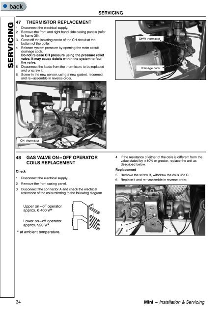
47 THERMISTOR REPLACEMENT<br />
1 Disconnect the electrical supply.<br />
2 Remove the front <strong>and</strong> right h<strong>and</strong> side casing panels (refer<br />
to frame 36).<br />
3 Close off the isolating cocks of the CH circuit at the<br />
bottom of the boiler.<br />
4 Release system pressure by opening the main circuit<br />
drainage cock.<br />
Do not release CH pressure using the pressure relief<br />
valve. It may cause debris within the system to foul<br />
the valve.<br />
5 Disconnect the leads from the thermistors to be replaced<br />
<strong>and</strong> unscrew it .<br />
6 Screw in the new sensor, using a new gasket, reconnect<br />
<strong>and</strong> re---assemble in reverse order.<br />
DHW thermistor<br />
Drainage cock<br />
CH thermistor<br />
48 GAS VALVE ON---OFF OPERATOR<br />
COILS REPLACEMENT<br />
Check<br />
1 Disconnect the electrical supply.<br />
2 Remove the front casing panel.<br />
3 Disconnect the connector A <strong>and</strong> check the electrical<br />
resistance of the coils referring to the following diagram<br />
4 If the resistance of either of the coils is different from the<br />
value stated by ±10% or greater, replace the unit as<br />
described below.<br />
Replacement<br />
5 Remove the screw B, withdraw the coils unit C.<br />
6 Replace it <strong>and</strong> re---assemble in reverse order.<br />
Upper on---off operator<br />
approx. 6 400 W*<br />
Lower on---off operator<br />
approx. 920 W*<br />
A<br />
* at ambient temperature.<br />
B<br />
C<br />
34<br />
Mini --- Installation & Servicing