899883192 - Valiant
899883192 - Valiant
899883192 - Valiant

Create successful ePaper yourself
Turn your PDF publications into a flip-book with our unique Google optimized e-Paper software.
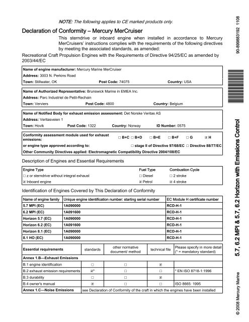
NOTE: The following applies to CE marked products only.<br />
Declaration of Conformity – Mercury MerCruiser<br />
This sterndrive or inboard engine when installed in accordance to Mercury<br />
MerCruisers’ instructions complies with the requirements of the following directives<br />
by meeting the associated standards, as amended:<br />
Recreational Craft Propulsion Engines with the Requirements of Directive 94/25/EC as amended by<br />
2003/44/EC<br />
Name of engine manufacturer: Mercury Marine MerCruiser<br />
Address: 3003 N. Perkins Road<br />
Town: Stillwater, OK Post Code: 74075 Country: USA<br />
Name of Authorized Representative: Brunswick Marine in EMEA Inc.<br />
Address: Parc Industriel de Petit‐Rechain<br />
Town: Verviers Post Code: 4800 Country: Belgium<br />
Name of Notified Body for exhaust emission assessment: Det Norske Veritas AS<br />
Address: Veritasveien 1<br />
Town: Hovik Post Code: 1322 Country: Norway ID Number: 0575<br />
Conformity assessment module used for exhaust<br />
emissions:<br />
or engine type approved according to:<br />
☐ B+C ☐ B+D ☐ B+E ☐ B+F ☐ G ☒ H<br />
☐ stage II of Directive 97/68/EC ☐ Directive 88/77/EC<br />
Other Community Directives applied: Electromagnetic Compatibility Directive 2004/108/EC<br />
Description of Engines and Essential Requirements<br />
Engine Type Fuel Type Combustion Cycle<br />
☐ z or sterndrive without integral exhaust ☐ Diesel ☐ 2 stroke<br />
☒ Inboard engine ☒ Petrol ☒ 4 stroke<br />
Identification of Engines Covered by This Declaration of Conformity<br />
Name of engine family Unique engine identification number: starting serial number EC Module H certificate number<br />
5.7 MPI (EC) 1A090000 RCD-H-1<br />
6.2 MPI (EC) 1A091600 RCD-H-1<br />
Horizon 5.7 (EC) 1A090000 RCD-H-1<br />
Horizon 6.2 (EC) 1A091600 RCD-H-1<br />
Horizon 8.1 (EC) 1A090000 RCD-H-1<br />
8.1 HO (EC) 1A090000 RCD-H-1<br />
Essential requirements<br />
Annex 1.B—Exhaust Emissions<br />
standards<br />
other normative<br />
document/ method<br />
technical file<br />
B.1 engine identification ☐ ☐ ☒<br />
Please specify in more detail<br />
(* = mandatory standard)<br />
B.2 exhaust emission requirements ☒* ☐ ☐ * EN ISO 8718‐1:1996<br />
B.3 durability ☐ ☐ ☒<br />
B.4 owner's manual ☒ ☐ ☐ ISO 8665: 1995<br />
Annex 1.C—Noise Emissions<br />
see Declaration of Conformity of the craft in which the engines have been installed<br />
1108<br />
© 2008 Mercury Marine 5.7, 6.2 MPI & 5.7, 6.2 Horizon with Emissions Control<br />
*<strong>899883192</strong>*<br />
90-<strong>899883192</strong>
This declaration of comformity is issued under the sole responsibility of the manufacturer. I declare on behalf of the engine<br />
manufacturer that the engines will meet the exhaust emission requirements of Directive 94/25/EC as amended by Directive 2003/44/<br />
EC when installed in a recreational craft, in accordance with the engine manufacturer's supplied instructions and that these engines<br />
must not be put into service until the recreational craft into which they are to be installed has been declared in conformity with the<br />
relevant provisions of the above mentioned Directives.<br />
Name / function:<br />
Kevin Grodski, President, Mercury MerCuiser<br />
Signature and title:<br />
Regulatory contact:<br />
Regulations and Product Safety Department<br />
Mercury Marine<br />
W6250 W. Pioneer Road<br />
Fond du Lac, WI 54936<br />
USA<br />
Identification Record<br />
Please record the following information:<br />
Date and place of issue: July 24, 2008<br />
Stillwater, Oklahoma, USA<br />
Engine Model and Horsepower<br />
Engine Serial Number<br />
Transom Assembly Serial Number (Sterndrive) Gear Ratio Sterndrive Unit Serial Number<br />
Transmission Model (Inboard) Gear Ratio Transmission Serial Number<br />
Propeller Number Pitch Diameter<br />
Hull Identification Number (HIN)<br />
Purchase Date<br />
Boat Manufacturer Boat Model Length<br />
The serial numbers are the manufacturer’s keys to numerous engineering details that apply<br />
to your Mercury MerCruiser® power package. When contacting your Authorized Mercury<br />
MerCruiser Dealer about service, always specify model and serial numbers.<br />
The description and specifications contained herein were in effect at the time this guide<br />
was approved for printing. Mercury Marine, whose policy is one of continuous<br />
improvement, reserves the right to discontinue models at any time, or to change<br />
specifications or designs, without notice and without incurring obligation.<br />
Mercury Marine, Fond du Lac, Wisconsin, U.S.A. Printed in U.S.A.<br />
© 2008, Mercury Marine<br />
Mercury, Mercury Marine, MerCruiser, Mercury MerCruiser, Mercury Racing, Mercury<br />
Precision Parts, Mercury Propellers, Mariner, Quicksilver, #1 On The Water, Alpha, Bravo,<br />
Bravo Two, Pro Max, OptiMax, Sport‐Jet, K‐Planes, MerCathode, RideGuide, SmartCraft,<br />
Zero Effort, VesselView, Zeus, Axius, Total Command, M with Waves logo, Mercury with<br />
Waves logo, and SmartCraft logo are all trademarks or registered trademarks of Brunswick<br />
Corporation. Mercury Product Protection logo is a registered service mark of Brunswick<br />
Corporation.
Welcome<br />
You have selected one of the finest marine power packages available. It incorporates<br />
numerous design features to assure operating ease and durability.<br />
With proper care and maintenance, you will thoroughly enjoy using this product for many<br />
boating seasons. To ensure maximum performance and carefree use, we ask that you<br />
thoroughly read this manual.<br />
The Operation, Maintenance and Warranty Manual contains specific instructions for using<br />
and maintaining your product. We suggest that this manual remain with the product for<br />
ready reference whenever you are on the water.<br />
Thank you for purchasing one of our Mercury MerCruiser products. We sincerely hope your<br />
boating will be pleasant!<br />
Mercury MerCruiser<br />
Warranty Message<br />
The product you have purchased comes with a limited warranty from Mercury Marine;<br />
the terms of the warranty are set forth in the Warranty Sections of this manual. The warranty<br />
statement contains a description of what is covered, what is not covered, the duration of<br />
coverage, how to best obtain warranty coverage, important disclaimers and limitations of<br />
damages and other related information. Please review this important information.<br />
Mercury Marine products are designed and manufactured to comply with our own high<br />
quality standards, applicable industry standards and regulations, as well as certain<br />
emissions regulations. At Mercury Marine every engine is operated and tested before it is<br />
boxed for shipment to make sure that the product is ready for use. In addition, certain<br />
Mercury Marine products are tested in a controlled and monitored environment, for up to<br />
10 hours of engine run time, in order to verify and make a record of compliance with<br />
applicable standards and regulations. All Mercury Marine product, sold as new, receives<br />
the applicable limited warranty coverage, whether the engine participated in one of the test<br />
programs described above or not.<br />
Read This Manual Thoroughly<br />
IMPORTANT: If you don’t understand any portion of this manual, contact your dealer for a<br />
demonstration of actual starting and operating procedures.<br />
Notice<br />
Throughout this publication, and on your power package, dangers, warnings, cautions, and<br />
notices, accompanied by the International Hazard Symbol ! , may be used to alert the<br />
installer/user to special instructions concerning a particular service or operation that may<br />
be hazardous if performed incorrectly or carelessly. Observe them carefully.<br />
These Safety Alerts alone cannot eliminate the hazards that they signal. Strict compliance<br />
with these special instructions while performing the service, plus common sense operation,<br />
are major accident prevention measures.<br />
! DANGER<br />
Indicates a hazardous situation which, if not avoided, will result in death or serious injury.<br />
! WARNING<br />
Indicates a hazardous situation which, if not avoided, could result in death or serious<br />
injury.
! CAUTION<br />
Indicates a hazardous situation which, if not avoided, could result in minor or moderate<br />
injury.<br />
NOTICE<br />
Indicates a situation which, if not avoided, could result in engine or major component<br />
failure.<br />
IMPORTANT: Identifies information essential to the successful completion of the task.<br />
NOTE: Indicates information that helps in the understanding of a particular step or action.<br />
! WARNING<br />
The operator (driver) is responsible for the correct and safe operation of the boat, the<br />
equipment aboard and the safety of all occupants aboard. We strongly recommend that<br />
the operator read this Operation, Maintenance and Warranty Manual and thoroughly<br />
understand the operational instructions for the power package and all related accessories<br />
before the boat is used.<br />
! WARNING<br />
The engine exhaust from this product contains chemicals known to the state of California<br />
to cause cancer, birth defects or other reproductive harm.
TABLE OF CONTENTS<br />
Section 1 - Warranty<br />
Warranty Registration: United States and<br />
Canada....................................................................2<br />
Warranty Registration: Outside the United States and<br />
Canada....................................................................2<br />
Transfer of Warranty................................................3<br />
Mercury Product Protection Plan: United States and<br />
Canada....................................................................3<br />
Mercury MerCruiser Limited Warranty<br />
(Gasoline‐Fueled Products Only) ...........................4<br />
3‐Year Limited Warranty Against Corrosion............6<br />
Global Warranty Charts...........................................7<br />
Warranty for Consumer Applications................7<br />
Warranty for Commercial Applications.............7<br />
Warranty for Government Applications............8<br />
Warranty for Consumer Applications................8<br />
Warranty for Commercial Applications.............8<br />
Warranty for Government Applications............9<br />
Warranty for Consumer Applications................9<br />
Warranty for Commercial Applications.............9<br />
Warranty for Government Applications..........10<br />
Warranty for Consumer Applications..............10<br />
Warranty for Commercial Applications...........10<br />
Warranty for Government Applications..........11<br />
Global Warranty Charts.........................................11<br />
Consumer Application Warranty Chart.............12<br />
Commercial Application Warranty Chart...........13<br />
Government Application Warranty Chart..........14<br />
Mercury Installation Quality Certification Program 14<br />
California Emissions Limited Warranty..................15<br />
What Is Covered...............................................15<br />
Duration Of Coverage.......................................16<br />
How To Obtain Warranty Coverage..................17<br />
What Mercury Will Do.......................................17<br />
What Is Not Covered........................................17<br />
Components Of The Emission Control System 17<br />
Disclaimers And Limitations..............................19<br />
California Emission Control Warranty Statement..19<br />
Your Warranty Rights and Obligations.............19<br />
Manufacturer's Warranty Coverage..................19<br />
Owner's Warranty Responsibilities...................19<br />
Emission Control Information Label.......................20<br />
Owner Responsibility........................................21<br />
Emission Certification Star Label...........................21<br />
Section 2 - Getting to Know Your Power Package<br />
Identification..........................................................24<br />
Engine Serial Number Decal..........................24<br />
Transmissions................................................24<br />
Velvet Drive Transmissions .........................24<br />
ZF Marine Transmissions.............................25<br />
Walter V‐Drive Transmissions......................26<br />
Lanyard Stop Switch..............................................26<br />
Instrumentation......................................................27<br />
VesselView.....................................................27<br />
Digital Gauges................................................28<br />
Analog Gauges...............................................29<br />
Remote Controls (Non‐DTS Models).....................29<br />
Remote Controls............................................29<br />
Panel Mount Features..................................30<br />
Console Mount Features..............................31<br />
Zero Effort Features.......................................31<br />
Remote Controls (DTS Models)............................32<br />
Remote Controls............................................32<br />
Panel Mount Features....................................32<br />
Console Mount Features ‐ Single Engine.......33<br />
Slim Binnacle Console Mount Features ‐ Single<br />
Engine............................................................34<br />
Console Mount Features‐ Dual Engine..........35<br />
Synchronizing Dual Engines..........................35<br />
Dual Helm Station Transfer............................36<br />
Synchronizing Dual Helms Prior To Station<br />
Transfer........................................................37<br />
Zero Effort Features.......................................37<br />
Electrical System Overload Protection..................37<br />
Audio Warning System..........................................40<br />
Caution.............................................................40<br />
Severe..............................................................40<br />
OBDM...............................................................41<br />
Testing The Audio Warning System.................41<br />
Guardian Strategy.................................................41<br />
90-<strong>899883192</strong> NOVEMBER 2008 Page i
Section 3 - On the Water<br />
Safe Boating Suggestions....................................44<br />
Be Alert to Carbon Monoxide Poisoning.............. 45<br />
Good Ventilation.............................................. 45<br />
Poor Ventilation .............................................. 46<br />
Basic Boat Operation (Non‐DTS Models)............ 46<br />
Launching and Boat Operation..................... 46<br />
Operation Chart.......................................... 46<br />
Starting and Stopping the Engine................. 47<br />
Starting the Engine..................................... 47<br />
Stopping the Engine....................................48<br />
Throttle‐Only Operation.................................48<br />
Freezing Temperature Operation..................48<br />
Drain Plug and Bilge Pump...........................48<br />
Basic Boat Operation (DTS Models).................... 48<br />
Launching and Boat Operation..................... 48<br />
Operation Chart.......................................... 48<br />
Starting and Stopping the Engine................. 49<br />
Starting the Engine..................................... 49<br />
Stopping the Engine....................................50<br />
Throttle‐Only Operation.................................50<br />
Freezing Temperature Operation..................51<br />
Drain Plug and Bilge Pump...........................51<br />
Protecting People in the Water.............................51<br />
While You Are Cruising....................................51<br />
While Boat Is Stationary.................................. 51<br />
High‐Speed and High‐Performance Operation.... 52<br />
Passenger Safety in Pontoon Boats and Deck<br />
Boats.................................................................... 52<br />
Boats Having An Open Front Deck..................52<br />
Boats With Front‐Mounted, Raised Pedestal<br />
Fishing Seats...................................................52<br />
Wave and Wake Jumping.................................... 53<br />
Impact with Underwater Hazards......................... 53<br />
Conditions Affecting Operation.............................54<br />
Weight Distribution (Passengers and Gear)<br />
Inside the Boat.............................................. 54<br />
The Bottom of the Boat................................. 54<br />
Cavitation...................................................... 54<br />
Ventilation..................................................... 55<br />
Elevation and Climate................................... 55<br />
Getting Started..................................................... 55<br />
20‐Hour Break‐In Period............................... 55<br />
After Break‐In Period.....................................55<br />
End of First Season Checkup....................... 56<br />
Section 4 - Specifications<br />
Cruising RPM....................................................... 58<br />
Fuel Requirements...............................................58<br />
Fuel Ratings.....................................................58<br />
Using Reformulated (Oxygenated) Gasoline<br />
(USA Only).......................................................58<br />
Gasoline Containing Alcohol........................... 58<br />
Engine Oil.............................................................59<br />
Engine Specifications...........................................60<br />
Inboard 5.7 MPI with Emissions Control....... 60<br />
Inboard 6.2 MPI with Emissions Control....... 61<br />
Horizon 5.7 with Emissions Control.............. 62<br />
Horizon 6.2 with Emissions Control.............. 62<br />
Engine Specifications...........................................63<br />
Fluid Specifications.............................................. 64<br />
Engine...........................................................64<br />
Transmission.................................................64<br />
Section 5 - Maintenance<br />
Owner/Operator Responsibilities..........................66<br />
Dealer Responsibilities.........................................66<br />
Maintenance.........................................................66<br />
Do‐It‐Yourself Maintenance Suggestions.............67<br />
Inspection.............................................................67<br />
Maintenance Schedule—Inboard Models............ 68<br />
Routine Maintenance.................................... 68<br />
Scheduled Maintenance................................68<br />
Maintenance Log..................................................69<br />
Engine Oil.............................................................70<br />
Checking....................................................... 70<br />
Filling.............................................................70<br />
Changing Oil and Filter................................. 71<br />
Engine Oil Drain Pump..................................71<br />
Changing the Oil Filter.................................. 72<br />
Transmission Fluid............................................... 72<br />
Checking While the Engine is Warm............... 72<br />
Checking While Engine is Cold........................73<br />
Changing......................................................... 73<br />
Engine Coolant.....................................................73<br />
Page ii 90-<strong>899883192</strong> NOVEMBER 2008
Checking........................................................73<br />
Filling..............................................................74<br />
Changing .......................................................75<br />
Battery...................................................................75<br />
Multiple EFI Engine Battery Precautions........75<br />
Cleaning the Flame Arrestor..................................76<br />
Positive Crankcase Ventilation Valve (PCV)....77<br />
Changing......................................................77<br />
Cleaning The IAC Muffler......................................77<br />
Water‐Separating Fuel Filter.................................78<br />
GEN III Models...............................................79<br />
Removal.......................................................79<br />
Installation....................................................80<br />
Lubrication.............................................................80<br />
Throttle Cable.................................................80<br />
Transmission Linkage....................................81<br />
Serpentine Drive Belt.............................................82<br />
Checking...........................................................82<br />
Replacing Belt and/or Adjusting Tension..........82<br />
Flushing The Power Package................................83<br />
Horizon Models.................................................83<br />
The Boat Out of the Water................................85<br />
The Boat In the Water.......................................86<br />
Section 6 - Storage<br />
Cold Weather or Extended Storage.......................92<br />
Preparing Power Package for Storage...........92<br />
Engine and Fuel System Preparation..........93<br />
Draining the Seawater System..............................94<br />
Drain System Identification.............................94<br />
Air Actuated Single Point Drain System.......94<br />
Three Point Manual Drain System...............95<br />
Air‐Actuated Single‐Point Drain System.........95<br />
Boat in the Water.........................................95<br />
Boat out of the Water...................................97<br />
Three‐Point Manual Drain System.................99<br />
Boat in the Water.........................................99<br />
Boat out of the Water.................................100<br />
Battery Storage....................................................101<br />
Power Package Recommissioning......................101<br />
Section 7 - Troubleshooting<br />
Diagnosing EFI Problems....................................104<br />
Diagnosing DTS Problems..................................104<br />
Engine Guardian System.....................................104<br />
Troubleshooting Charts.......................................104<br />
Starter Motor Will Not Crank Engine, or Cranks<br />
Slowly...........................................................104<br />
Engine Will Not Start or Is Hard to Start.......105<br />
Engine Runs Rough, Misses, or Backfires...105<br />
Poor Performance........................................105<br />
Excessive Engine Temperature...................105<br />
Insufficient Engine Temperature..................106<br />
Low Engine Oil Pressure..............................106<br />
Battery Will Not Recharge............................106<br />
Remote Control Is Difficult to Move, Has<br />
Excessive Play, or Makes Unusual Sounds. 106<br />
Steering Wheel Jerks or Is Difficult to Turn..107<br />
Section 8 - Customer Assistance Information<br />
Owner Service Assistance...................................110<br />
Local Repair Service.......................................110<br />
Service Away From Home..............................110<br />
Stolen Power Package...................................110<br />
Attention Required after Submersion..............110<br />
Replacement Service Parts............................110<br />
Parts and Accessories Inquiries.................111<br />
Resolving a Problem.......................................111<br />
Mercury Marine Service Offices......................111<br />
Ordering Literature..............................................112<br />
United States and Canada..............................112<br />
Outside The United States and Canada.........112<br />
90-<strong>899883192</strong> NOVEMBER 2008 Page iii
Page iv 90-<strong>899883192</strong> NOVEMBER 2008
Table of Contents<br />
Section 1 - Warranty<br />
Section 1 - Warranty<br />
1<br />
Warranty Registration: United States and Canada<br />
.............................................................................. 2<br />
Warranty Registration: Outside the United States<br />
and Canada.......................................................... 2<br />
Transfer of Warranty............................................. 3<br />
Mercury Product Protection Plan: United States and<br />
Canada................................................................. 3<br />
Mercury MerCruiser Limited Warranty<br />
(Gasoline‐Fueled Products Only) ........................ 4<br />
3‐Year Limited Warranty Against Corrosion......... 6<br />
Global Warranty Charts........................................ 7<br />
Warranty for Consumer Applications..............7<br />
Warranty for Commercial Applications............7<br />
Warranty for Government Applications...........8<br />
Warranty for Consumer Applications..............8<br />
Warranty for Commercial Applications............8<br />
Warranty for Government Applications...........9<br />
Warranty for Consumer Applications..............9<br />
Warranty for Commercial Applications............9<br />
Warranty for Government Applications.........10<br />
Warranty for Consumer Applications............10<br />
Warranty for Commercial Applications..........10<br />
Warranty for Government Applications.........11<br />
Global Warranty Charts...................................... 11<br />
Consumer Application Warranty Chart ......... 12<br />
Commercial Application Warranty Chart ...... 13<br />
Government Application Warranty Chart .....14<br />
Mercury Installation Quality Certification Program<br />
............................................................................ 14<br />
California Emissions Limited Warranty............... 15<br />
What Is Covered .......................................... 15<br />
Duration Of Coverage .................................. 16<br />
How To Obtain Warranty Coverage ............. 17<br />
What Mercury Will Do .................................. 17<br />
What Is Not Covered .................................... 17<br />
Components Of The Emission Control System<br />
..................................................................... 17<br />
Disclaimers And Limitations ......................... 19<br />
California Emission Control Warranty Statement<br />
............................................................................ 19<br />
Your Warranty Rights and Obligations ......... 19<br />
Manufacturer's Warranty Coverage ............. 19<br />
Owner's Warranty Responsibilities .............. 19<br />
Emission Control Information Label.................... 20<br />
Owner Responsibility ................................... 21<br />
Emission Certification Star Label........................ 21<br />
90-<strong>899883192</strong> NOVEMBER 2008 Page 1
Section 1 - Warranty<br />
Warranty Registration: United States and Canada<br />
To ensure that your warranty coverage begins promptly, your selling dealer should fill out<br />
the Warranty Registration Card completely and mail it to the factory immediately upon sale<br />
of the new product.<br />
The Warranty Registration Card identifies the name and address of the original purchaser,<br />
product model and serial number(s), date of sale, type of use and selling dealer’s code,<br />
name, and address. The dealer also certifies that you are the original purchaser and user<br />
of the product. A temporary Owner Warranty Registration Card will be presented to you<br />
when you purchase the product.<br />
Upon receipt of the Warranty Registration Card at the factory, Mercury MerCruiser will send<br />
you an owner resource guide that includes your warranty registration confirmation. If you<br />
do not receive your owner resource guide within 60 days from date of new product sale,<br />
please contact your selling dealer.<br />
Because of your selling dealer’s ongoing interest in your satisfaction, the product should<br />
be returned to him for warranty service.<br />
The product warranty is not effective until the product is registered at the factory.<br />
NOTE: Registration lists must be maintained by the factory and dealer on marine products<br />
sold in the United States in the event that a safety recall notification under the Federal Boat<br />
Safety Act is required.<br />
You may change your address at any time, including at time of warranty claim, by calling<br />
Mercury MerCruiser or sending a letter or fax to Mercury MerCruiser’s warranty registration<br />
department with your name, old address, new address, and engine serial number. Your<br />
dealer can also process this change of information.<br />
United States customers or dealers may contact:<br />
Mercury Marine<br />
Attn: Warranty Registration Department<br />
W6250 Pioneer Road<br />
P.O. Box 1939<br />
Fond du Lac, WI 54936-1939<br />
920-929-5054<br />
Fax 920-929-5893<br />
Canadian customers or dealers may contact:<br />
Mercury Marine Canada Limited<br />
2395 Meadowpine Blvd.<br />
Mississauga, ON<br />
Canada, L5N 7W6<br />
Fax 1-800-663-8334<br />
Warranty Registration: Outside the United States and Canada<br />
To ensure that your warranty coverage begins promptly, your selling dealer should fill out<br />
the warranty registration card completely and mail it to the distributor responsible for<br />
administering the warranty registration and claim program for your area.<br />
Page 2 90-<strong>899883192</strong> NOVEMBER 2008
Transfer of Warranty<br />
Section 1 - Warranty<br />
The warranty registration card identifies your name and address, product model and serial<br />
numbers, date of sale, type of use, and the selling distributor’s and dealer’s code number,<br />
name, and address. The distributor or dealer also certifies that you are the original<br />
purchaser and user of the product. A copy of the warranty registration card, designated as<br />
the purchaser’s copy, MUST be given to you immediately after the card has been<br />
completely filled out by the selling distributor or dealer. This card represents your factory<br />
registration identification. Keep the card; if you ever need warranty service on this product,<br />
your dealer may ask you for the warranty registration card to verify date of purchase and<br />
to use the information on the card to prepare the warranty claim forms.<br />
In some countries, the distributor will issue a permanent (plastic) warranty registration card<br />
to you within 30 days after receiving the factory copy of the warranty registration card from<br />
your distributor or dealer. If you receive a plastic warranty registration card, you may<br />
discard the purchaser’s copy that you received from the distributor or dealer when you<br />
purchased the product. Ask your distributor or dealer if this plastic card program applies to<br />
you. For further information concerning the warranty registration card and its relationship<br />
to warranty claim processing, refer to the International Warranty. See Table of Contents.<br />
NOTE: Registration lists must be maintained by the factory and dealer on marine products<br />
sold in the United States in the event of a safety recall notification under the Federal Boat<br />
Safety Act.<br />
The limited warranty is transferable to a subsequent purchaser, but only for the remainder<br />
of the unused portion of the limited warranty. This will not apply to products used for<br />
commercial applications.<br />
To transfer the warranty to the subsequent owner, send or fax a copy of the bill of sale or<br />
purchase agreement, new owner’s name, address and engine serial number to Mercury<br />
Marine’s warranty registration department. In the United States mail to:<br />
Mercury Marine<br />
Attn: Warranty Registration Department<br />
W6250 W. Pioneer Road<br />
P.O. Box 1939<br />
Fond du Lac, WI 54936-1939<br />
920-929-5054<br />
Fax 920-929-5893<br />
In Canada mail to:<br />
Mercury Marine Canada Limited<br />
2395 Meadowpine Blvd.<br />
Mississauga, ON<br />
Canada, L5N 7W6<br />
Fax 1-800-663-8334<br />
Upon processing the transfer of warranty, Mercury Marine will send registration verification<br />
to the new owner of the product by mail.<br />
There is no charge for this service.<br />
For products purchased outside the United States and Canada, contact the distributor in<br />
your country, or the distributor closest to you.<br />
Mercury Product Protection Plan: United States and Canada<br />
(Certain performance products, triple engine installations, and commercial applications are<br />
excluded.)<br />
90-<strong>899883192</strong> NOVEMBER 2008 Page 3
Section 1 - Warranty<br />
The Mercury Product Protection Plan provides coverage against unexpected mechanical<br />
and electrical breakdowns that may occur beyond the standard limited warranty.<br />
The optional Mercury Product Protection Plan is the only Factory Plan available for your<br />
engine.<br />
One‐, two‐, three‐, four‐, or five‐ year term plans can be purchased up to 12 months after<br />
the original engine registration date.<br />
See your participating Mercury MerCruiser dealer for complete program details.<br />
Mercury MerCruiser Limited Warranty (Gasoline‐Fueled Products<br />
Only)<br />
Mercury MerCruiser Limited Warranty (Gasoline-Fueled Products Only)<br />
What is Covered<br />
Mercury Marine warrants its new products to be free of defects in material and workmanship during the period described following.<br />
Duration of Coverage<br />
Warranty Period for Recreational Use<br />
The warranty period begins on the date the product is first sold to a recreational‐use retail purchaser or the date on which the<br />
product is first put into service, whichever occurs first. Products installed by an Installation Quality Certified Installer receive one<br />
(1) year of additional warranty coverage. The repair or replacement of parts or the performance of service under this warranty<br />
does not extend the life of this warranty beyond its original expiration date. The warranty period is specific to the model covered;<br />
see your model for the base coverage period:<br />
Coverage for Sterndrive Models with Closed Cooling, Inboard Models, Scorpion 377 Models, and Vazer 100<br />
Models The Limited Warranty for Sterndrive Models with Closed Cooling, Inboard Models, Scorpion 377 Models, and<br />
Vazer 100 Models is four (4) years when installed by an Installation Quality Certified Installer or three (3) years for<br />
noncertified installations.<br />
Coverage for SeaCore Sterndrive Models<br />
The Limited Warranty for SeaCore Sterndrive Models is four (4) years when installed by an Installation Quality Certified<br />
Installer or three (3) years for noncertified installations.<br />
Coverage for Standard Models<br />
The Limited Warranty for Standard Models, which do not include Sterndrive Models with Closed Cooling, Inboard Models,<br />
Scorpion 377 Models, Vazer 100 Models, or SeaCore Sterndrive Models, is two (2) years when installed by an Installation<br />
Quality Certified Installer or one (1) year for noncertified installations.<br />
Warranty Period for Commercial Use<br />
The warranty period begins on the date the product is first sold to a commercial‐use retail purchaser or the date on which the<br />
product is first put into service, whichever occurs first. Commercial users of these products receive warranty coverage for either<br />
one (1) year from the date of first retail sale or the accumulation of 500 hours of operation, whichever occurs first. Commercial<br />
use is defined as any work‐related or employment‐related use of the product, or any use of the product that generates income<br />
for any part of the warranty period, even if the product is only occasionally used for such purposes. The repair or replacement<br />
of parts or the performance of service under this warranty does not extend the life of this warranty beyond its original expiration<br />
date.<br />
Transfer of Coverage<br />
Unexpired warranty coverage can be transferred from one recreational‐use customer to a subsequent recreational‐use customer<br />
upon proper reregistration of the product. Unexpired warranty coverage cannot be transferred either to or from a commercial‐use<br />
customer.<br />
Termination of Coverage<br />
Warranty coverage is terminated for used product obtained in any of the following ways:<br />
• Repossession from a retail customer<br />
• Purchase at auction<br />
• Purchase from a salvage yard<br />
• Purchase from an insurance company that obtained the product as a result of an insurance claim<br />
Page 4 90-<strong>899883192</strong> NOVEMBER 2008
Section 1 - Warranty<br />
Conditions That Must Be Met in Order to Obtain Warranty Coverage<br />
Warranty coverage is available only to retail customers that purchase from a dealer authorized by Mercury Marine to distribute the<br />
product in the country in which the sale occurred, and then only after the pre‐delivery inspection process specified by Mercury Marine<br />
is completed and documented. Warranty coverage becomes available upon proper registration of the product by the authorized<br />
dealer. Inaccurate warranty registration information regarding recreational use or subsequent change of use from recreational to<br />
commercial (unless properly reregistered) may void the warranty at the sole discretion of Mercury Marine. Routine maintenance<br />
must be performed according to the maintenance schedule in the Operation, Maintenance & Warranty manual in order to obtain<br />
warranty coverage. Mercury Marine reserves the right to make any warranty coverage contingent upon proof of proper maintenance.<br />
What Mercury Marine Will Do<br />
Mercury Marine's sole and exclusive obligation under this warranty is limited to, at our option, repairing a defective part, replacing<br />
such part or parts with new or Mercury Marine certified remanufactured parts, or refunding the purchase price of the Mercury Marine<br />
product. Mercury Marine reserves the right to improve or modify products from time to time without assuming an obligation to modify<br />
products previously manufactured.<br />
How to Obtain Warranty Coverage<br />
The customer must provide Mercury Marine with a reasonable opportunity to repair and reasonable access to the product for warranty<br />
service. Warranty claims shall be made by delivering the product for inspection to a Mercury Marine dealer authorized to service the<br />
product. If the purchaser cannot deliver the product to such a dealer, written notice must be given to Mercury Marine. Mercury Marine<br />
will then arrange for the inspection and any covered repair. The purchaser in that case shall pay for all related transportation charges<br />
and travel time. If the service provided is not covered by this warranty, the purchaser shall pay for all related labor and material and<br />
any other expenses associated with that service. The purchaser shall not, unless requested by Mercury Marine, ship the product or<br />
parts of the product directly to Mercury Marine. Proof of registered ownership must be presented to the dealer at the time warranty<br />
service is requested in order to obtain coverage.<br />
What Is Not Covered<br />
This limited warranty does not cover the following:<br />
• Routine maintenance items<br />
• Adjustments<br />
• Normal wear and tear<br />
• Damage caused by abuse<br />
• Abnormal use<br />
• Use of a propeller or gear ratio that does not allow the engine to run in its recommended RPM range (see the Operation,<br />
Maintenance & Warranty manual)<br />
• Operation of the product in a manner inconsistent with the recommended operation and duty cycle section of the Operation,<br />
Maintenance & Warranty manual<br />
• Neglect<br />
• Accident<br />
• Submersion<br />
• Improper installation (proper installation specifications and techniques are set forth in the installation instructions for the product)<br />
• Improper service<br />
• Use of an accessory or part that was not manufactured or sold by Mercury Marine and that damages the Mercury product<br />
• Jet pump impellers and liners<br />
• Operation with fuels, oils, or lubricants that are not suitable for use with the product (see the Operation, Maintenance & Warranty<br />
manual)<br />
• Alteration or removal of parts<br />
• Water entering the engine through the fuel intake, air intake, or exhaust system or damage to the product from insufficient<br />
cooling water caused by blockage of the cooling system by a foreign body<br />
• Running the engine out of water<br />
• Mounting the engine too high on the transom<br />
• Operating the boat with the engine over trimmed<br />
90-<strong>899883192</strong> NOVEMBER 2008 Page 5
Section 1 - Warranty<br />
Use of the product for racing or other competitive activity, or operating with a racing‐type lower unit at any point, even by a previous<br />
owner of the product, voids the warranty. Expenses related to haul‐out, launch, towing, storage, telephone, rental, inconvenience,<br />
slip fees, insurance coverage, loan payments, loss of time, loss of income, or any other type of incidental or consequential damages<br />
are not covered by this warranty. Also, expenses associated with the removal or replacement of boat partitions or other material in<br />
order to gain access to the product are not covered by this warranty. No individual or entity, including Mercury Marine authorized<br />
dealers, has been given authority by Mercury Marine to make any affirmation, representation, or warranty regarding the product,<br />
other than those contained in this limited warranty. If such affirmation, representation, or warranty is made, it shall not be enforceable<br />
against Mercury Marine.<br />
DISCLAIMERS AND LIMITATIONS<br />
THE IMPLIED WARRANTIES OF MERCHANTABILITY AND FITNESS FOR A PARTICULAR PURPOSE ARE EXPRESSLY<br />
DISCLAIMED. TO THE EXTENT THAT THEY CANNOT BE DISCLAIMED, THE IMPLIED WARRANTIES ARE LIMITED IN<br />
DURATION TO THE LIFE OF THE EXPRESS WARRANTY. INCIDENTAL AND CONSEQUENTIAL DAMAGES ARE EXCLUDED<br />
FROM COVERAGE UNDER THIS WARRANTY. SOME STATES/COUNTRIES DO NOT ALLOW FOR THE DISCLAIMERS,<br />
LIMITATIONS AND EXCLUSIONS IDENTIFIED ABOVE. AS A RESULT, THEY MAY NOT APPLY TO YOU. THIS WARRANTY<br />
GIVES YOU SPECIFIC LEGAL RIGHTS, AND YOU MAY ALSO HAVE OTHER LEGAL RIGHTS WHICH VARY FROM STATE<br />
TO STATE AND COUNTRY TO COUNTRY.<br />
3‐Year Limited Warranty Against Corrosion<br />
3-YEAR LIMITED WARRANTY AGAINST CORROSION<br />
What Is Covered<br />
Duration of Coverage<br />
Mercury Marine warrants that each new Mercury, Mariner, Mercury Racing, Sport Jet, M 2 Jet Drive, Tracker<br />
by Mercury Marine Outboard, MerCruiser Inboard or Sterndrive engine (Product) will not be rendered<br />
inoperative as a direct result of corrosion for the period of time described below.<br />
This limited corrosion warranty provides coverage for three (3) years from either the date the product is first<br />
sold, or the date on which the product is first put into service, whichever occurs first. The repair and<br />
replacement of parts, or the performance of service under this warranty does not extend the life of this<br />
warranty beyond its original expiration date. Unexpired warranty coverage can be transferred to subsequent<br />
(noncommercial use) purchaser upon proper re‐registration of the product. Warranty coverage is terminated<br />
for used product repossessed from a retail customer, purchased at auction, from a salvage yard, or from an<br />
insurance company that obtained the product as a result of an insurance claim.<br />
Condition That Must Be Met in Order to Obtain Warranty Coverage<br />
What Mercury Will Do<br />
How to Obtain Warranty Coverage<br />
What Is Not Covered<br />
Warranty coverage is available only to retail customers that purchase from a dealer authorized by Mercury<br />
Marine to distribute the product in the country in which the sale occurred, and then only after the Mercury<br />
Marine specified pre‐delivery inspection process is completed and documented. Warranty coverage<br />
becomes available upon proper registration of the product by the authorized dealer. Corrosion prevention<br />
devices specified in the Operation, Maintenance & Warranty manual must be in use on the boat, and routine<br />
maintenance outlined in the Operation, Maintenance & Warranty manual must be timely performed (including<br />
without limitation the replacement of sacrificial anodes, use of specified lubricants, and touch‐up of nicks<br />
and scratches) in order to maintain warranty coverage. Mercury Marine reserves the right to make warranty<br />
coverage contingent upon proof of proper maintenance.<br />
Mercury's sole and exclusive obligation under this warranty is limited to, at our option, repairing a corroded<br />
part, replacing such part or parts with new or Mercury Marine certified re‐manufactured parts, or refunding<br />
the purchase price of the Mercury product. Mercury reserves the right to improve or modify products from<br />
time to time without assuming an obligation to modify products previously manufactured.<br />
The customer must provide Mercury with a reasonable opportunity to repair, and reasonable access to the<br />
product for warranty service. Warranty claims shall be made by delivering the product for inspection to a<br />
Mercury dealer authorized to service the product. If purchaser cannot deliver the product to such a dealer,<br />
written notice must be given to Mercury. We will then arrange for the inspection and any covered repair.<br />
Purchaser in that case shall pay for all related transportation charges and/or travel time. If the service<br />
provided is not covered by this warranty, purchaser shall pay for all related labor and material, and any other<br />
expenses associated with that service. Purchaser shall not, unless requested by Mercury, ship the product<br />
or parts of the product directly to Mercury. Proof of registered ownership must be presented to the dealer at<br />
the time warranty service is requested in order to obtain coverage.<br />
Page 6 90-<strong>899883192</strong> NOVEMBER 2008
Global Warranty Charts<br />
Section 1 - Warranty<br />
This limited warranty does not cover electrical system corrosion; corrosion resulting from damage, corrosion<br />
which causes purely cosmetic damage, abuse or improper service; corrosion to accessories, instruments,<br />
steering systems; corrosion to factory installed jet drive unit; damage due to marine growth; product sold<br />
with less than a one year limited Product warranty; replacement parts (parts purchased by the Customer);<br />
products used in a commercial application. Commercial use is defined as any work or employment related<br />
use of the product, or any use of the product which generates income, for any part of warranty period, even<br />
if the product is only occasionally used for such purposes.<br />
Warranty for Consumer Applications<br />
Engine Model<br />
Inboard 5.7 MPI with<br />
Emissions Control<br />
Region<br />
The Americas (excluding<br />
Brazil)<br />
Brazil<br />
Europe, Middle East,<br />
Africa<br />
Australia, New Zealand<br />
Standard Factory Limited Warranty by<br />
Certification Status of Boat Manufacturer<br />
Not Certified<br />
1 year<br />
2 years<br />
Installation Quality<br />
Certified<br />
2 years<br />
3 years<br />
2 years<br />
Consumer Limited<br />
Corrosion Warranty<br />
3 years<br />
2 years<br />
3 years<br />
Japan 1 year 1 year 1 year<br />
South Pacific 2 years 2 years 2 years<br />
Other Asia 1 year 1 year 1 year<br />
Warranty for Commercial Applications<br />
Engine Model<br />
Inboard 5.7 MPI with<br />
Emissions Control<br />
Region<br />
The Americas (excluding<br />
Brazil)<br />
Standard Factory Limited Warranty by<br />
Certification Status of Boat Manufacturer<br />
Not Certified<br />
Installation Quality<br />
Certified<br />
Commercial Limited<br />
Corrosion Warranty<br />
1 year 1 year 1 year<br />
Brazil 2 years 2 years 2 years<br />
Europe, Middle East,<br />
Africa<br />
Australia, New Zealand<br />
Japan<br />
South Pacific<br />
Other Asia<br />
1 year or 500 hours 1 year or 500 hours 1 year or 500 hours<br />
90-<strong>899883192</strong> NOVEMBER 2008 Page 7
Section 1 - Warranty<br />
Warranty for Government Applications<br />
Engine Model<br />
Imboard 5.7 MPI with<br />
Emissions Control<br />
Region<br />
The Americas (excluding<br />
Brazil)<br />
Standard Factory Limited Warranty by<br />
Certification Status of Boat Manufacturer<br />
Not Certified<br />
Installation Quality<br />
Certified<br />
Government Limited<br />
Corrosion Warranty<br />
1 year 1 year 3 years<br />
Brazil 2 years 2 years 2 years<br />
Europe, Middle East,<br />
Africa<br />
Australia, New Zealand<br />
Japan<br />
South Pacific<br />
Other Asia<br />
1 year or 500 hours 1 year or 500 hours<br />
3 years<br />
1 year or 500 hours<br />
Warranty for Consumer Applications<br />
Engine Model<br />
Inboard 6.2 MPI with<br />
Emissions Control<br />
Region<br />
The Americas (excluding<br />
Brazil)<br />
Brazil<br />
Europe, Middle East,<br />
Africa<br />
Australia, New Zealand<br />
Standard Factory Limited Warranty by<br />
Certification Status of Boat Manufacturer<br />
Not Certified<br />
1 year<br />
2 years<br />
Installation Quality<br />
Certified<br />
2 years<br />
3 years<br />
2 years<br />
Consumer Limited<br />
Corrosion Warranty<br />
3 years<br />
2 years<br />
3 years<br />
Japan 1 year 1 year 1 year<br />
South Pacific 2 years 2 years 2 years<br />
Other Asia 1 year 1 year 1 year<br />
Warranty for Commercial Applications<br />
Engine Model<br />
Inboard 6.2 MPI with<br />
Emissions Control<br />
Region<br />
The Americas (excluding<br />
Brazil)<br />
Standard Factory Limited Warranty by<br />
Certification Status of Boat Manufacturer<br />
Not Certified<br />
Installation Quality<br />
Certified<br />
Commercial Limited<br />
Corrosion Warranty<br />
1 year 1 year 1 year<br />
Brazil 2 years 2 years 2 years<br />
Europe, Middle East,<br />
Africa<br />
Australia, New Zealand<br />
Japan<br />
South Pacific<br />
Other Asia<br />
1 year or 500 hours 1 year or 500 hours 1 year or 500 hours<br />
Page 8 90-<strong>899883192</strong> NOVEMBER 2008
Warranty for Government Applications<br />
Section 1 - Warranty<br />
Engine Model<br />
Inboard 6.2 MPI with<br />
Emissions Control<br />
Region<br />
The Americas (excluding<br />
Brazil)<br />
Standard Factory Limited Warranty by<br />
Certification Status of Boat Manufacturer<br />
Not Certified<br />
Installation Quality<br />
Certified<br />
Government Limited<br />
Corrosion Warranty<br />
1 year 1 year 3 years<br />
Brazil 2 years 2 years 2 years<br />
Europe, Middle East,<br />
Africa<br />
Australia, New Zealand<br />
Japan<br />
South Pacific<br />
Other Asia<br />
1 year or 500 hours 1 year or 500 hours<br />
3 years<br />
1 year or 500 hours<br />
Warranty for Consumer Applications<br />
Engine Model<br />
Horizon 5.7 with<br />
Emissions Control<br />
Region<br />
The Americas (excluding<br />
Brazil)<br />
Brazil<br />
Europe, Middle East,<br />
Africa<br />
Australia, New Zealand<br />
Standard Factory Limited Warranty by<br />
Certification Status of Boat Manufacturer<br />
Not Certified<br />
3 years<br />
2 years<br />
Installation Quality<br />
Certified<br />
2 years<br />
3 years<br />
2 years<br />
Consumer Limited<br />
Corrosion Warranty<br />
3 years<br />
2 years<br />
3 years<br />
Japan 1 year 1 year 1 year<br />
South Pacific 2 years 2 years 2 years<br />
Other Asia 1 year 1 year 1 year<br />
Warranty for Commercial Applications<br />
Engine Model<br />
Horizon 5.7 with<br />
Emissions Control<br />
Region<br />
The Americas (excluding<br />
Brazil)<br />
Standard Factory Limited Warranty by<br />
Certification Status of Boat Manufacturer<br />
Not Certified<br />
Installation Quality<br />
Certified<br />
Commercial Limited<br />
Corrosion Warranty<br />
1 year 1 year 1 year<br />
Brazil 2 years 2 years 2 years<br />
Europe, Middle East,<br />
Africa<br />
Australia, New Zealand<br />
Japan<br />
South Pacific<br />
Other Asia<br />
1 year or 500 hours 1 year or 500 hours 1 year or 500 hours<br />
90-<strong>899883192</strong> NOVEMBER 2008 Page 9
Section 1 - Warranty<br />
Warranty for Government Applications<br />
Engine Model<br />
Horizon 5.7 with<br />
Emissions Control<br />
Region<br />
The Americas (excluding<br />
Brazil)<br />
Standard Factory Limited Warranty by<br />
Certification Status of Boat Manufacturer<br />
Not Certified<br />
Installation Quality<br />
Certified<br />
Government Limited<br />
Corrosion Warranty<br />
1 year 1 year 3 years<br />
Brazil 2 years 2 years 2 years<br />
Europe, Middle East,<br />
Africa<br />
Australia, New Zealand<br />
Japan<br />
South Pacific<br />
Other Asia<br />
1 year or 500 hours 1 year or 500 hours<br />
3 years<br />
1 year or 500 hours<br />
Warranty for Consumer Applications<br />
Engine Model<br />
Horizon 6.2 with<br />
Emissions Control<br />
Region<br />
The Americas (excluding<br />
Brazil)<br />
Brazil<br />
Europe, Middle East,<br />
Africa<br />
Australia, New Zealand<br />
Standard Factory Limited Warranty by<br />
Certification Status of Boat Manufacturer<br />
Not Certified<br />
Installation Quality<br />
Certified<br />
Consumer Limited<br />
Corrosion Warranty<br />
3 years 4 years 3 years<br />
2 years<br />
2 years 2 years<br />
3 years<br />
2 years<br />
3 years<br />
Japan 1 year 1 year 1 year<br />
South Pacific 2 years 2 years 2 years<br />
Other Asia 1 year 1 year 1 year<br />
Warranty for Commercial Applications<br />
Engine Model<br />
Horizon 6.2 with<br />
Emissions Control<br />
Region<br />
The Americas (excluding<br />
Brazil)<br />
Standard Factory Limited Warranty by<br />
Certification Status of Boat Manufacturer<br />
Not Certified<br />
Installation Quality<br />
Certified<br />
Commercial Limited<br />
Corrosion Warranty<br />
1 year 1 year 1 year<br />
Brazil 2 years 2 years 2 years<br />
Europe, Middle East,<br />
Africa<br />
Australia, New Zealand<br />
Japan<br />
South Pacific<br />
Other Asia<br />
1 year or 500 hours 1 year or 500 hours 1 year or 500 hours<br />
Page 10 90-<strong>899883192</strong> NOVEMBER 2008
Warranty for Government Applications<br />
Section 1 - Warranty<br />
Engine Model<br />
Horizon 6.2 with<br />
Emissions Control<br />
Region<br />
The Americas (excluding<br />
Brazil)<br />
Standard Factory Limited Warranty by<br />
Certification Status of Boat Manufacturer<br />
Not Certified<br />
Installation Quality<br />
Certified<br />
Government Limited<br />
Corrosion Warranty<br />
1 year 1 year 3 years<br />
Brazil 2 years 2 years 2 years<br />
Europe, Middle East,<br />
Africa<br />
Australia, New Zealand<br />
Japan<br />
South Pacific<br />
Other Asia<br />
1 year or 500 hours 1 year or 500 hours<br />
3 years<br />
1 year or 500 hours<br />
Global Warranty Charts<br />
IMPORTANT: Please refer to www.mercurymarine.com/global_warranty for the most<br />
currant Global Warranty Charts.<br />
90-<strong>899883192</strong> NOVEMBER 2008 Page 11
Section 1 - Warranty<br />
Consumer Application Warranty Chart<br />
Consumer Application: Standard Factory Limited Warranty by Region & Boat Brand<br />
Region Standard SeaCore<br />
USA and<br />
Canada<br />
Latin<br />
America<br />
Limited Corrosion<br />
Warranty<br />
Non-Certified Boat Brand Certified Boat Brand All Boat Brands<br />
Vazer and<br />
Models<br />
with<br />
Closed<br />
Cooling<br />
Scorpion<br />
377<br />
Standard<br />
SeaCore<br />
Vazer and<br />
Models<br />
with<br />
Closed<br />
Cooling<br />
Scorpion<br />
377<br />
Vazer,<br />
Standard<br />
Models,<br />
and and<br />
Models<br />
with<br />
Closed<br />
Cooling<br />
SeaCore<br />
1 year 3 years 3 years 3 years 2 years 4 years 4 years 4 years 3 years 4 years<br />
1 year 3 years 1 year 1 year 2 years 4 years 2 years 2 years 3 years 4 years<br />
Mexico 1 year 3 years 1 year 1 year 1 year 4 years 1 year 1 year 1 year 4 years<br />
Europe 2 years 3 years 2 years 2 years 3 years 4 years 3 years 3 years 3 years 4 years<br />
Japan 1 year 1 year 1 year 1 year 1 year 1 year 1 year 1 year 1 year 1 year<br />
Australia<br />
and New<br />
Zealand<br />
South<br />
Pacific<br />
Asia<br />
(excluding<br />
Japan,<br />
South<br />
Pacific,<br />
Australia,<br />
New<br />
Zealand)<br />
2 years 3 years 3 years<br />
3 years all<br />
Tow<br />
Sports<br />
2 years 3 years 3 years<br />
3 years all<br />
Tow<br />
Sports<br />
3 years 4 years<br />
1 year 3 years 1 year 1 year 1 year 3 years 1 year 1 year 3 years 4 years<br />
2 years 2 years 2 years<br />
3 years all<br />
Tow<br />
Sports<br />
2 years 2 years 2 years<br />
3 years all<br />
Tow<br />
Sports<br />
NOTE: In regions where the Certified Boat Builder program is not applicable, the regular warranty always applies.<br />
2 years 2 years<br />
NOTE: In regions where TBD (To Be Determined) is listed, check with your local dealer for warranty length and conditions.<br />
Page 12 90-<strong>899883192</strong> NOVEMBER 2008
Commercial Application Warranty Chart<br />
Section 1 - Warranty<br />
Commercial Application: Standard Factory Limited Warranty by Region & Boat Brand<br />
Region Standard SeaCore<br />
USA and<br />
Canada<br />
Latin<br />
America<br />
1 year or<br />
500 hours<br />
1 year or<br />
500 hours<br />
Limited Corrosion<br />
Warranty<br />
Non-Certified Boat Brand Certified Boat Brand All Boat Brands<br />
1 year or<br />
500 hours<br />
1 year or<br />
500 hours<br />
Vazer and<br />
Models<br />
with<br />
Closed<br />
Cooling<br />
1 year or<br />
500 hours<br />
1 year or<br />
500 hours<br />
Scorpion<br />
377<br />
1 year or<br />
500 hours<br />
1 year or<br />
500 hours<br />
Standard<br />
1 year or<br />
500 hours<br />
1 year or<br />
500 hours<br />
SeaCore<br />
1 year or<br />
500 hours<br />
1 year or<br />
500 hours<br />
Vazer and<br />
Models<br />
with<br />
Closed<br />
Cooling<br />
1 year or<br />
500 hours<br />
1 year or<br />
500 hours<br />
Scorpion<br />
377<br />
1 year or<br />
500 hours<br />
1 year or<br />
500 hours<br />
Vazer,<br />
Standard<br />
Models,<br />
and and<br />
Models<br />
with<br />
Closed<br />
Cooling<br />
none<br />
SeaCore<br />
Mexico 1 year 1 year 1 year 1 year 1 year 1 year 1 year 1 year 1 year 1 year<br />
Europe<br />
Japan<br />
Australia<br />
and New<br />
Zealand<br />
South<br />
Pacific<br />
Asia<br />
(excluding<br />
Japan,<br />
South<br />
Pacific,<br />
Australia,<br />
New<br />
Zealand)<br />
1 year or<br />
500 hours<br />
1 year or<br />
500 hours<br />
1 year or<br />
500 hours<br />
1 year or<br />
500 hours<br />
1 year or<br />
500 hours<br />
1 year or<br />
500 hours<br />
1 year or<br />
500 hours<br />
1 year or<br />
500 hours<br />
1 year or<br />
500 hours<br />
1 year or<br />
500 hours<br />
1 year or<br />
500 hours<br />
1 year or<br />
500 hours<br />
1 year or<br />
500 hours<br />
1 year or<br />
500 hours<br />
1 year or<br />
500 hours<br />
1 year or<br />
500 hours<br />
1 year or<br />
500 hours<br />
1 year or<br />
500 hours<br />
1 year or<br />
500 hours<br />
1 year or<br />
500 hours<br />
1 year or<br />
500 hours<br />
1 year or<br />
500 hours<br />
1 year or<br />
500 hours<br />
1 year or<br />
500 hours<br />
1 year or<br />
500 hours<br />
1 year or<br />
500 hours<br />
1 year or<br />
500 hours<br />
1 year or<br />
500 hours<br />
1 year or<br />
500 hours<br />
1 year or<br />
500 hours<br />
1 year or<br />
500 hours<br />
1 year or<br />
500 hours<br />
1 year or<br />
500 hours<br />
1 year or<br />
500 hours<br />
1 year or<br />
500 hours<br />
1 year or<br />
500 hours<br />
1 year or<br />
500 hours<br />
1 year or<br />
500 hours<br />
1 year or<br />
500 hours<br />
1 year or<br />
500 hours<br />
NOTE: In regions where the Certified Boat Builder program is not applicable, the regular warranty always applies<br />
none<br />
none<br />
none<br />
none<br />
none<br />
none<br />
none<br />
none<br />
none<br />
none<br />
none<br />
none<br />
none<br />
90-<strong>899883192</strong> NOVEMBER 2008 Page 13
Section 1 - Warranty<br />
Government Application Warranty Chart<br />
Government Application: Standard Factory Limited Warranty by Region & Boat Brand<br />
Region Standard SeaCore<br />
USA and<br />
Canada<br />
Latin<br />
America<br />
Limited Corrosion<br />
Warranty<br />
Non-Certified Boat Brand Certified Boat Brand All Boat Brands<br />
Vazer and<br />
Models<br />
with<br />
Closed<br />
Cooling<br />
Scorpion<br />
377<br />
Standard<br />
SeaCore<br />
Vazer and<br />
Models<br />
with<br />
Closed<br />
Cooling<br />
Scorpion<br />
377<br />
Vazer,<br />
Standard<br />
Models,<br />
and and<br />
Models<br />
with<br />
Closed<br />
Cooling<br />
SeaCore<br />
1 year 3 years 3 years 3 years 2 years 4 years 4 years 4 years 3 years 4 years<br />
1 year or<br />
500 hours<br />
1 year or<br />
500 hours<br />
1 year or<br />
500 hours<br />
1 year or<br />
500 hours<br />
1 year or<br />
500 hours<br />
1 year or<br />
500 hours<br />
1 year or<br />
500 hours<br />
1 year or<br />
500 hours<br />
Mexico 1 year 1 year 1 year 1 year 1 year 1 year 1 year 1 year 1 year 1year<br />
Europe<br />
Japan<br />
Australia<br />
and New<br />
Zealand<br />
South<br />
Pacific<br />
Asia<br />
(excluding<br />
Japan,<br />
South<br />
Pacific,<br />
Australia,<br />
New<br />
Zealand)<br />
1 year or<br />
500 hours<br />
1 year or<br />
500 hours<br />
1 year or<br />
500 hours<br />
1 year or<br />
500 hours<br />
1 year or<br />
500 hours<br />
1 year or<br />
500 hours<br />
1 year or<br />
500 hours<br />
1 year or<br />
500 hours<br />
1 year or<br />
500 hours<br />
1 year or<br />
500 hours<br />
1 year or<br />
500 hours<br />
1 year or<br />
500 hours<br />
1 year or<br />
500 hours<br />
1 year or<br />
500 hours<br />
1 year or<br />
500 hours<br />
1 year or<br />
500 hours<br />
1 year or<br />
500 hours<br />
1 year or<br />
500 hours<br />
1 year or<br />
500 hours<br />
1 year or<br />
500 hours<br />
1 year or<br />
500 hours<br />
1 year or<br />
500 hours<br />
1 year or<br />
500 hours<br />
1 year or<br />
500 hours<br />
1 year or<br />
500 hours<br />
1 year or<br />
500 hours<br />
1 year or<br />
500 hours<br />
1 year or<br />
500 hours<br />
1 year or<br />
500 hours<br />
1 year or<br />
500 hours<br />
1 year or<br />
500 hours<br />
1 year or<br />
500 hours<br />
1 year or<br />
500 hours<br />
1 year or<br />
500 hours<br />
1 year or<br />
500 hours<br />
1 year or<br />
500 hours<br />
1 year or<br />
500 hours<br />
1 year or<br />
500 hours<br />
1 year or<br />
500 hours<br />
1 year or<br />
500 hours<br />
NOTE: In regions where the Certified Boat Builder program is not applicable, the regular warranty always applies<br />
Mercury Installation Quality Certification Program<br />
none<br />
none<br />
none<br />
none<br />
none<br />
none<br />
none<br />
none<br />
none<br />
none<br />
none<br />
none<br />
15502<br />
Page 14 90-<strong>899883192</strong> NOVEMBER 2008
Section 1 - Warranty<br />
Mercury MerCruiser products installed by a Mercury Installation Quality Certified<br />
Manufacturer are Installation Quality certified products and may receive an additional one<br />
(1) year of limited warranty coverage.<br />
The Installation Quality Certification program was developed to recognize MerCruiser<br />
boatbuilder customers who have achieved higher manufacturing standards. It is the first<br />
and only comprehensive manufacturer‐installation certification program in the industry.<br />
The program has three goals:<br />
1. To enhance overall product quality.<br />
2. To improve the boat ownership experience.<br />
3. To enhance overall customer satisfaction.<br />
The certification process is designed to review all facets of manufacturing and engine<br />
installation. The program is composed of design, manufacturing and installation review<br />
stages with which builders must comply. Certification applies leading‐edge methodologies<br />
to create:<br />
• Efficiencies and best practices specific to engine installation.<br />
• World‐class assembly and component specifications.<br />
• Efficient installation processes.<br />
• Industry standard end‐of‐line test procedures<br />
Boat builders that successfully complete the program and meet all certification<br />
requirements earn Installation Quality System Certified Manufacturer status and receive<br />
an additional one (1) year of Mercury limited factory warranty coverage on all<br />
MerCruiser‐powered boats that are registered on and after the boat builder's certification<br />
date for all worldwide registrations.<br />
Mercury has designated a section of our Website to promote the Installation Quality<br />
Certification Program and communicate its benefits to consumers. For a current list of<br />
MerCruiser‐powered boat brands that have earned Installation Quality Certification, visit<br />
www.mercurymarine.com/mercruiser_warranty.<br />
California Emissions Limited Warranty<br />
What Is Covered<br />
NOTE: Mercury Marine does not establish model years for the Mercury MerCruiser product<br />
line. In order to comply with CARB warranty regulations, and for that limited purpose only,<br />
model year shall have the same meaning as calendar year. As an example, 2003 model<br />
year products refers to products manufactured during calendar year 2003.<br />
The California Air Resources Board has promulgated air emissions regulations for inboard<br />
and sterndrive engines. The regulations apply to all inboard and sterndrive engines that<br />
were manufactured for the 2003 model year and later. Mercury Marine, in compliance with<br />
those regulations, provides this limited warranty for the emission control systems (see the<br />
components of the emission control system listed following), and further warrants that the<br />
inboard or sterndrive engine was designed, built, and equipped to conform with all<br />
applicable regulations adopted by the California Air Resources Board pursuant to its<br />
authority in Chapters 1 and 2, Part 5, Division 26 of the Health and Safety Code. For<br />
information regarding the limited warranty for the non‐emissions related components of the<br />
inboard or sterndrive engine, please see the limited warranty statement for your engine.<br />
NOTE: Mercury Marine does not establish model years for the Mercury MerCruiser product<br />
line. In order to comply with CARB warranty regulations, and for that limited purpose only,<br />
model year shall have the same meaning as calendar year. As an example, 2003 model<br />
year products refers to products manufactured during calendar year 2003.<br />
90-<strong>899883192</strong> NOVEMBER 2008 Page 15
Section 1 - Warranty<br />
Duration Of Coverage<br />
NOTE: Your dealer will register your engine for warranty coverage for you. The warranty<br />
registration process is not related in any way to the process of obtaining a license, title or<br />
registration from state boating authorities. You should ask your dealer to update your<br />
warranty registration information to reflect a change of address or a transfer of ownership.<br />
(This change may be made at any time.) See the Warranty Registration section of your<br />
manual or your dealer for more information.<br />
Mercury Marine warrants the components of the emissions control systems (see the<br />
components of the emission control system listed following) of its new, 2003 model year<br />
and later California certified inboard and sterndrive engines, registered to a California<br />
resident, to be free from defects in material or workmanship that cause the failure of a<br />
warranted part to be identical in all material respects to that part as described in the<br />
application of Mercury Marine for certification from the California Air Resources Board, for<br />
the period of time, and under the conditions identified below. The cost to diagnose a<br />
warranty failure is covered under the warranty (if the warranty claim is approved). Damage<br />
to other engine components caused by the failure of a warranted part will also be repaired<br />
under warranty.<br />
NOTE: Mercury Marine does not establish model years for the Mercury MerCruiser product<br />
line. In order to comply with CARB warranty regulations, and for that limited purpose only,<br />
model year shall have the same meaning as calendar year. As an example, 2003 model<br />
year products refers to products manufactured during calendar year 2003<br />
This limited warranty provides coverage for the components of the emissions control<br />
systems. Select emission control parts from model year 2003‐2005 (inboard or sterndrive)<br />
engines are warranted for 2 years from either the date the product is first sold, or first put<br />
into service, whichever occurs first. Select emission control parts from 2006‐2007 (inboard<br />
or sterndrive) engines are warranted for 2 years from either the date the product is first<br />
sold, or first put into service, whichever occurs first. Select emission control parts from 2008<br />
(inboard or sterndrive) engines are warranted for 3 years or 480 hours, whichever first<br />
occurs, from either the date the product is first sold, or first put into service, whichever<br />
occurs first. Select emission control parts from 2009 and later (inboard or sterndrive)<br />
engines are warranted for 3 years or 480 hours, whichever first occurs, from either the date<br />
the product is first sold, or first put into service, whichever occurs first. Emission related<br />
normal maintenance items such as spark plugs and filters, that are on the warranted parts<br />
list (see following) are warranted up to their first required replacement interval only. (See<br />
Maintenance Schedule). The repair or replacement of parts, or the performance of service<br />
under this warranty, does not extend the life of this warranty beyond its original expiration<br />
date. Unexpired warranty coverage can be transferred to a subsequent purchaser. (See<br />
instructions on transfer of warranty). Warranty coverage is terminated for used product<br />
repossessed from a retail customer, purchased at auction, from a salvage yard, or from an<br />
insurance company that obtained the product as a result of an insurance claim.<br />
Page 16 90-<strong>899883192</strong> NOVEMBER 2008
How To Obtain Warranty Coverage<br />
What Mercury Will Do<br />
What Is Not Covered<br />
Section 1 - Warranty<br />
The customer must provide Mercury with a reasonable opportunity to repair and reasonable<br />
access to the product for warranty service. Warranty claims shall be made by delivering<br />
the product for inspection to a Mercury dealer authorized to service the product. If<br />
purchaser cannot deliver the product to such a dealer, please notify Mercury Marine and<br />
Mercury will then arrange for the inspection and any covered repair. Purchaser in that case<br />
shall pay for all related transportation charges and/or travel time. If the service provided is<br />
not covered by this warranty, purchaser shall pay for all related labor and material, and any<br />
other expenses associated with that service. Purchaser shall not, unless requested by<br />
Mercury, ship the product or parts of the product directly to Mercury. Proof of registered<br />
ownership must be presented to the dealer at the time warranty service is requested in<br />
order to obtain coverage.<br />
Mercury Marine's sole and exclusive obligation under this warranty is limited to, at our<br />
expense and at our option, repairing or replacing defective parts with new or Mercury<br />
Marine certified re‐manufactured parts, or refunding the purchase price of the Mercury<br />
product. Mercury reserves the right to improve or modify products from time to time without<br />
assuming an obligation to modify products previously manufactured.<br />
This limited warranty does not cover routine maintenance items, tune ups, adjustments,<br />
normal wear and tear, damage caused by abuse, abnormal use, use of a propeller or gear<br />
ratio that does not allow the engine to run in its recommended wide‐open‐throttle RPM<br />
range (see Specifications), operation of the product in a manner inconsistent with the<br />
recommended operation procedures, neglect, accident, submersion, improper installation<br />
(proper installation specifications and techniques are set forth in the installation instructions<br />
for the product), improper service, use of an accessory or part not manufactured or sold<br />
by us, jet pump impellers and liners, operation with fuels, oils or lubricants which are not<br />
suitable for use with the product (see Specifications), alteration or removal of parts, or water<br />
entering the engine through the fuel intake, air intake or exhaust system. Use of the product<br />
for racing or other competitive activity, or operating with a racing type lower unit, at any<br />
point, even by a prior owner of the product, voids the warranty.<br />
Expenses related to haul‐out, launch, towing, storage, telephone, rental, inconvenience,<br />
slip fees, insurance coverage, loan payments, loss of time, loss of income, or any other<br />
type of incidental or consequential damages are not covered by this warranty. Also,<br />
expenses associated with the removal and/or replacement of boat partitions or material<br />
caused by boat design for access to the product are not covered by this warranty.<br />
Non‐warranty maintenance, replacement, or repair of emission control devices and<br />
systems may be performed by any marine engine repair establishment or individual. The<br />
use of non‐Mercury parts for non‐warranty maintenance or repairs will not be grounds for<br />
disallowing other warranty work. The use of add‐on (as defined at section 1900 (b)(1) and<br />
(b)(10) of Title 13 of the California Code of Regulations) or modified parts not exempted<br />
by the California Air Resources Board may be grounds for disallowing a warranty claim, at<br />
the discretion of Mercury Marine. Failures of warranted parts caused by the use of a<br />
non‐exempted add‐on or modified part will not be covered.<br />
Components Of The Emission Control System<br />
1. Fuel Metering System<br />
a. Carburetor and internal parts (and/or pressure regulator or fuel injection system)<br />
b. Air/fuel ratio feedback and control system<br />
90-<strong>899883192</strong> NOVEMBER 2008 Page 17
Section 1 - Warranty<br />
c. Cold start enrichment system<br />
d. Intake valve(s)<br />
2. Air Induction System<br />
a. Controlled hot air intake system<br />
b. Intake manifold<br />
c. Air filter<br />
d. Turbocharger systems<br />
e. Heat riser valve and assembly<br />
3. Ignition System<br />
a. Spark plugs<br />
b. Magneto or electronic ignition system<br />
c. Spark advance/retard system<br />
d. Ignition coil and/or control module<br />
e. Ignition wires<br />
4. Lubrication System<br />
a. Oil pump and internal parts<br />
b. Oil injector(s)<br />
c. Oil meter<br />
5. Positive Crankcase Ventilation (PCV) System<br />
a. PCV Valve<br />
b. Oil filler cap<br />
6. Exhaust System.<br />
a. Exhaust manifold<br />
b. Exhaust elbow<br />
c. Intermediate exhaust elbow<br />
d. Lower exhaust pipe<br />
e. Tailpipe<br />
7. Catalysts or Thermal Reactor System<br />
a. Catalytic converter<br />
b. Thermal reactor<br />
c. Exhaust manifold<br />
d. Exhaust valve(s)<br />
8. Miscellaneous Items Used in Above Systems<br />
a. Hoses, clamps, fittings, tubing, sealing gaskets or devices, and mounting<br />
hardware<br />
b. Pulleys, belts, and idlers<br />
c. Vacuum, temperature, check and time sensitive valves and switches<br />
d. Electronic controls<br />
Page 18 90-<strong>899883192</strong> NOVEMBER 2008
Section 1 - Warranty<br />
Disclaimers And Limitations<br />
DISCLAIMERS AND LIMITATIONS<br />
THE IMPLIED WARRANTIES OF MERCHANTABILITY AND FITNESS FOR A PARTICULAR PURPOSE<br />
ARE EXPRESSLY DISCLAIMED. TO THE EXTENT THAT THEY CANNOT BE DISCLAIMED, THE<br />
IMPLIED WARRANTIES ARE LIMITED IN DURATION TO THE LIFE OF THE EXPRESS WARRANTY.<br />
INCIDENTAL AND CONSEQUENTIAL DAMAGES ARE EXCLUDED FROM COVERAGE UNDER THIS<br />
WARRANTY. SOME STATES/COUNTRIES DO NOT ALLOW FOR THE DISCLAIMERS, LIMITATIONS<br />
AND EXCLUSIONS IDENTIFIED ABOVE. AS A RESULT, THEY MAY NOT APPLY TO YOU. THIS<br />
WARRANTY GIVES YOU SPECIFIC LEGAL RIGHTS, AND YOU MAY ALSO HAVE OTHER LEGAL<br />
RIGHTS WHICH VARY FROM STATE TO STATE AND COUNTRY TO COUNTRY.<br />
If you have any questions regarding your warranty rights and responsibilities, refer to<br />
Owner Service Assistance for contact information.<br />
California Emission Control Warranty Statement<br />
Your Warranty Rights and Obligations<br />
The California Air Resources Board is pleased to explain the emission control system<br />
warranty on your 2003 model year 1. and later inboard or sterndrive engine. In California,<br />
new inboard and sterndrive engines must be designed, built and equipped to meet the<br />
State's stringent anti‐smog standards. Mercury Marine must warrant the emission control<br />
system on your inboard or sterndrive engine for the periods of time listed below provided<br />
there has been no abuse, neglect or improper maintenance of your inboard or sterndrive<br />
engine.<br />
Your emission control system may include parts such as the carburetor or fuel injection<br />
system, the ignition system, and catalytic converter. Also included may be hoses, belts,<br />
connectors and other emission‐related assemblies.<br />
Where a warrantable condition exists, Mercury Marine will repair your inboard or sterndrive<br />
engine at no cost to you; including diagnosis, parts and labor.<br />
Manufacturer's Warranty Coverage<br />
For 2003‐2008 spark‐ignition inboard and sterndrive marine engines: Select emission<br />
control parts from model year 1. 2003‐2008 inboard and sterndrive engines are warranted<br />
for 2 years. If any emission‐related part on your engine is defective under warranty, the<br />
part will be repaired or replaced by Mercury Marine.<br />
Owner's Warranty Responsibilities<br />
As the inboard or sterndrive engine owner, you are responsible for the performance of the<br />
required maintenance listed in your owner's manual. Mercury Marine recommends that you<br />
retain all receipts covering maintenance on your inboard or sterndrive engine, but Mercury<br />
Marine cannot deny warranty solely for the lack of receipts or your failure to ensure the<br />
performance of all scheduled maintenance.<br />
As the inboard or sterndrive engine owner, you should however be aware that Mercury<br />
Marine may deny you warranty coverage if your inboard or sterndrive engine or a part has<br />
failed due to abuse, neglect, improper maintenance or unapproved modifications. Warranty<br />
coverage is terminated for used product repossessed from a retail customer, purchased<br />
at auction, from a salvage yard, or from an insurance company that obtained the product<br />
as a result of an insurance claim.<br />
1. Mercury Marine does not establish model years for the Mercury MerCruiser product line. In order to comply with CARB warranty<br />
regulations, and for that limited purpose only, model year shall have the same meaning as calendar year. As an example, 2003<br />
model year products refers to products manufactured during calendar year 2003.<br />
90-<strong>899883192</strong> NOVEMBER 2008 Page 19
Section 1 - Warranty<br />
You are responsible for presenting your inboard or sterndrive engine to a Mercury Marine<br />
dealer authorized to service the product as soon as a problem exists. The warranty repairs<br />
will be completed in a reasonable amount of time, not to exceed 30 days.<br />
If you have any questions regarding your warranty rights and responsibilities, refer to<br />
Owner Service Assistance for contact information.<br />
Emission Control Information Label<br />
A tamper‐resistant Emission Control Information label is affixed in a visible location to the<br />
engine at time of manufacture by Mercury MerCruiser. In addition to the required emissions<br />
statement, the label lists the engine serial number, family, STD (emission standard/level),<br />
date of manufacture (month, year), and the engine displacement. Please note that the low<br />
emissions certification will not affect the fit, function, or performance of the engines.<br />
Boatbuilders and dealers may not remove the label or the part it is affixed to before sale.<br />
If modifications are necessary, contact Mercury MerCruiser about the availability of<br />
replacement decals before proceeding.<br />
NOTE: When the CE mark is present in the lower right corner of the Emission Control<br />
Information Label on the engine, the Declaration of Conformance applies. Refer to the front<br />
page of this manual for further information.<br />
EMISSION CONTROL<br />
INFORMATION<br />
THIS ENGINE CONFORMS TO XXXX CALIFORNIA EMISSION<br />
REGULATIONS FOR SPARK IGNITION MARINE ENGINES<br />
REFER TO OWNER'S MANUAL FOR MAINTENANCE<br />
SPECIFICATIONS AND ADJUSTMENTS<br />
SERIAL #<br />
FAMILY<br />
STD.<br />
XXXXXXXX<br />
XXXXXXXXXXXX<br />
XX.X g/kW-hr<br />
D.O.M.<br />
DISP<br />
MMM YYYY<br />
X.XL<br />
Emission Control Label—California Emissions–Compliant<br />
"SERIAL#"—Engine Serial Number<br />
"FAMILY"—Engine Family<br />
"STD."—Emissions Standard<br />
"D.O.M."—Date of Manufacture<br />
"DISP"—Piston Displacement<br />
0575<br />
31656<br />
EMISSION CONTROL<br />
INFORMATION<br />
NOT FOR SALE IN CALIFORNIA<br />
REFER TO OWNER'S MANUAL FOR MAINTENANCE<br />
SPECIFICATIONS AND ADJUSTMENTS<br />
SERIAL #<br />
FAMILY<br />
STD.<br />
XXXXXXXX<br />
XXXXXXXXXXXX<br />
XX.X g/kW-hr<br />
D.O.M.<br />
DISP<br />
MMM YYYY<br />
X.XL<br />
Emission Control Label—Not for Sale in California<br />
"SERIAL#"—Engine Serial Number<br />
"FAMILY"—Engine Family<br />
31657<br />
Page 20 90-<strong>899883192</strong> NOVEMBER 2008
Owner Responsibility<br />
"STD."—Emissions Standard<br />
"D.O.M."—Date of Manufacture<br />
"DISP"—Piston Displacement<br />
Section 1 - Warranty<br />
The operator must have routine engine maintenance performed to maintain emission levels<br />
within prescribed certification standards.<br />
The operator may not modify the engine in any manner that alters the horsepower or allows<br />
emissions levels to exceed their factory specifications.<br />
Emission Certification Star Label<br />
Your boat is labeled on the hull with one of the following star labels. The Symbol for Cleaner<br />
Marine Engines Means:<br />
1. Cleaner Air and Water ‐ for a healthier lifestyle and environment.<br />
2. Better Fuel Economy ‐ burns up to 30‐40 percent less gas and oil than conventional<br />
carbureted two‐stroke engines, saving money and resources.<br />
3. Longer Emission Warranty ‐ Protects consumer for worry free operation.<br />
Beginning January 1, 2003, one Three‐Star or Four‐Star label will be included with each<br />
factory‐certified Mercury MerCruiser engine.<br />
All Mercury MerCruiser engines (500 hp and below) will have a Three‐Star Ultra Low<br />
Emission rating or Four‐Star Super Ultra Low Emission rating. The Star label identifies that<br />
these engines meet the California Air Resources Board's Sterndrive and Inboard marine<br />
engine 2007 and later exhaust emission standards. Engines meeting these standards have<br />
65‐90% lower emissions than One‐Star – Low Emissions engines.<br />
The Star label will be affixed on the left side of the hull as shown.<br />
a<br />
XX 1234 XX<br />
b<br />
a - Recommended location<br />
32770<br />
b - Secondary location<br />
90-<strong>899883192</strong> NOVEMBER 2008 Page 21
Section 1 - Warranty<br />
One Star - Low emission<br />
Two Stars - Very Low emission<br />
mc79569-1<br />
The one‐star label identifies personal watercraft, outboard,<br />
sterndrive and inboard engines that meet the Air Resources<br />
Board's Personal Watercraft and Outboard marine engine<br />
2001 exhaust emission standards. Engines meeting these<br />
standards have 75% lower emissions than conventional<br />
carbureted two‐stroke engines. These engines are<br />
equivalent to the U.S. EPA's 2006 standards for marine<br />
engines.<br />
FO<br />
IDA<br />
mc79570-1<br />
The two‐star label identifies personal watercraft, outboard,<br />
sterndrive and inboard engines that meet the Air Resources<br />
Board's Personal Watercraft and Outboard marine engine<br />
2004 exhaust emission standards. Engines meeting these<br />
standards have 20% lower emissions than One Star ‐<br />
Low‐Emission engines.<br />
Three Stars - Ultra Low emission<br />
A<br />
SS<br />
D<br />
mc79571-1<br />
The three‐star label identifies engines that meet the Air<br />
Resources Board's Personal Watercraft and Outboard<br />
marine engine 2008 exhaust emission standards or the<br />
Sterndrive and Inboard marine engine 2003 exhaust<br />
emission standards. Engines meeting these standards have<br />
65% lower emissions than One Star ‐ Low Emission engines.<br />
Four Stars - Super Ultra Low emission<br />
RN<br />
F<br />
T<br />
mc79572-1<br />
The Four Star label identifies engines that meet the Air<br />
Resources Board's Sterndrive and Inboard marine engine<br />
2009 exhaust emission standards. Personal Watercraft and<br />
Outboard marine engines may also comply with these<br />
standards. Engines meeting these standards have 90%<br />
lower emissions than One Star ‐ Low Emission engines.<br />
Page 22 90-<strong>899883192</strong> NOVEMBER 2008
Section 2 - Getting to Know Your Power Package<br />
Section 2 - Getting to Know Your Power Package<br />
Table of Contents<br />
Identification........................................................ 24<br />
Engine Serial Number Decal.........................24<br />
Transmissions...............................................24<br />
Velvet Drive Transmissions ................... 24<br />
ZF Marine Transmissions ....................... 25<br />
Walter V‐Drive Transmissions ................ 26<br />
Lanyard Stop Switch........................................... 26<br />
Instrumentation................................................... 27<br />
VesselView....................................................27<br />
Digital Gauges...............................................28<br />
Analog Gauges.............................................29<br />
Remote Controls (Non‐DTS Models).................. 29<br />
Remote Controls...........................................29<br />
Panel Mount Features ............................ 30<br />
Console Mount Features ........................ 31<br />
Zero Effort Features......................................31<br />
Remote Controls (DTS Models).......................... 32<br />
Remote Controls...........................................32<br />
Panel Mount Features...................................32<br />
Console Mount Features ‐ Single Engine.....33<br />
Slim Binnacle Console Mount Features ‐ Single<br />
Engine...........................................................34<br />
Console Mount Features‐ Dual Engine.........35<br />
Synchronizing Dual Engines.........................35<br />
Dual Helm Station Transfer...........................36<br />
Synchronizing Dual Helms Prior To Station<br />
Transfer .................................................. 37<br />
Zero Effort Features......................................37<br />
Electrical System Overload Protection............... 37<br />
Audio Warning System....................................... 40<br />
Caution ......................................................... 40<br />
Severe .......................................................... 40<br />
OBDM .......................................................... 41<br />
Testing The Audio Warning System ............. 41<br />
Guardian Strategy............................................... 41<br />
2<br />
90-<strong>899883192</strong> NOVEMBER 2008 Page 23
Section 2 - Getting to Know Your Power Package<br />
Identification<br />
The serial numbers are the manufacture's keys to numerous engineering details which<br />
apply to your MerCruiser power package. When contacting MerCruiser about service,<br />
always specify model and serial numbers.<br />
Engine Serial Number Decal<br />
The serial number decal is located on top of the engine.<br />
Serial numbers and maintenance color codes decal<br />
The engine serial number is also stamped in the engine block.<br />
Transmissions<br />
VELVET DRIVE TRANSMISSIONS<br />
On Velvet Drive In‐Line and V‐Drive Transmissions (71C, 72C, 72C V‐Drive, with or without<br />
Walter transmissions) the gear ratio (in forward gear) is marked on transmission<br />
identification plate. Transmission output shaft rotation and propeller rotation required (in<br />
forward gear) is indicated on a decal on transmission case. Transmission rotation is<br />
described when viewed from the rear of transmission.<br />
25902<br />
c<br />
b<br />
a<br />
7424<br />
In‐Line transmission shown (others similarly located)<br />
a - Transmission identification plate<br />
b - Gear ratio (in Forward gear)<br />
c - Output flange rotation decal (in<br />
Forward gear)<br />
Page 24 90-<strong>899883192</strong> NOVEMBER 2008
Section 2 - Getting to Know Your Power Package<br />
On the Velvet Drive 5000A and 5000V Transmissions the transmission identification plate<br />
indicates gear ratio, serial number and model.<br />
a<br />
7370<br />
Velvet Drive 5000A ‐ 8 degree down‐angle transmission shown (5000V ‐ V‐drive similar)<br />
a - Transmission identification plate<br />
ZF MARINE TRANSMISSIONS<br />
On the ZF Marine 8 Degree Down‐Angle and V‐Drive Transmissions, the transmission<br />
identification plate indicates gear ratio, serial number, and model.<br />
a<br />
7449<br />
Typical ZF Marine down‐angle transmission shown (V‐drive similar)<br />
a - Transmission identification plate<br />
90-<strong>899883192</strong> NOVEMBER 2008 Page 25
Section 2 - Getting to Know Your Power Package<br />
WALTER V-DRIVE TRANSMISSIONS<br />
On the Walter V‐Drive Transmissions, the transmission identification plate indicates gear<br />
ratio, serial number, and model.<br />
a<br />
7452<br />
Walter RV‐36 V‐drive<br />
a - Transmission identification plate<br />
Lanyard Stop Switch<br />
The purpose of a lanyard stop switch is to turn off the engine when the operator moves<br />
outside the operator's position (as in accidental ejection from the operator's position).<br />
b<br />
RUN<br />
a<br />
c<br />
a - Stop switch<br />
b - Lanyard<br />
74608<br />
c - Clips to the operator<br />
Accidental ejections, such as falling overboard, are more likely to occur in:<br />
• low‐sided sport boats<br />
• bass boats<br />
• high performance boats<br />
Accidental ejections can also occur from:<br />
• poor operating practices<br />
• sitting on the seat or gunwale at planing speeds<br />
• standing at planing speeds<br />
• operating at planing speeds in shallow or obstacle infested waters<br />
• releasing your grip on the steering wheel that is pulling in one direction<br />
Page 26 90-<strong>899883192</strong> NOVEMBER 2008
Instrumentation<br />
• consuming alcohol or drugs<br />
• high speed boating maneuvers<br />
Section 2 - Getting to Know Your Power Package<br />
The lanyard is a cord usually between 122 and 152 cm (4 and 5 ft) in length when stretched<br />
out, with an element on one end made to be inserted into the switch and a snap on the<br />
other end for attaching to the operator. The lanyard is coiled to make its at‐rest condition<br />
as short as possible to minimize the likelihood of lanyard entanglement with nearby objects.<br />
Its stretched‐out length is made to minimize the likelihood of accidental activation should<br />
the operator choose to move around in an area close to the normal operator's position. If<br />
it is desired to have a shorter lanyard, wrap the lanyard around the operator's wrist or leg,<br />
or tie a knot in the lanyard.<br />
Activation of the lanyard stop switch will stop the engine immediately, but the boat will<br />
continue to coast for some distance depending upon the velocity and degree of any turn<br />
at shut down. However, the boat will not complete a full circle. While the boat is coasting,<br />
it can cause injury to anyone in the boat's path as seriously as the boat would when under<br />
power.<br />
We strongly recommend that other occupants be instructed on proper starting and<br />
operating procedures should they be required to operate the engine in an emergency (e.g.<br />
if the operator is accidentally ejected).<br />
! WARNING<br />
If the operator falls out of the boat, stop the engine immediately to reduce the possibility<br />
of serious injury or death from being struck by the boat. Always properly connect the<br />
operator to the stop switch using a lanyard.<br />
Accidental or unintended activation of the switch during normal operation is also a<br />
possibility. This could cause any, or all, of the following potentially hazardous situations:<br />
• Occupants could be thrown forward due to unexpected loss of forward motion, a<br />
particular concern for passengers in the front of the boat who could be ejected over the<br />
bow and possibly struck by the propulsion or steering components.<br />
• Loss of power and directional control in heavy seas, strong current or high winds.<br />
• Loss of control when docking.<br />
! WARNING<br />
Avoid serious injury or death from deceleration forces resulting from accidental or<br />
unintended stop switch activation. The boat operator should never leave the operator's<br />
station without first disconnecting the stop switch lanyard from the operator.<br />
VesselView<br />
Your power package may come equipped with the following system viewer.<br />
90-<strong>899883192</strong> NOVEMBER 2008 Page 27
Section 2 - Getting to Know Your Power Package<br />
Your power package may be connected to a SmartCraft VesselView display. This display<br />
provides a single, easy‐to‐use source for real‐time information about a variety of vessel<br />
systems. The interactive VesselView display continuously monitors and reports information<br />
about speed and performance, trim angle, water temperature and depth, and other<br />
operating data. When VesselView detects a problem with any connected system, it displays<br />
an alarm message to signal the problem to the boat operator.<br />
Typical VesselView application<br />
24797<br />
VesselView may also be connected to other vessel systems, such as GPS, generators,<br />
and cabin environmental controls. This comprehensive vessel integration allows the<br />
operator to monitor and control a wide range of vessel systems from a single, convenient<br />
display.<br />
Digital Gauges<br />
A Mercury SmartCraft System instrument package can be purchased for this product. A<br />
few of the functions the instrument package will display are engine RPM, coolant<br />
temperature, oil pressure (requires a SmartCraft oil pressure sender kit), battery voltage,<br />
fuel consumption, and engine operating hours.<br />
SmartCraft digital gauges also feature troll control. This allows a vessel to maintain a<br />
constant speed with an engine speed between 500 and 1200 RPM.<br />
a<br />
b<br />
a - Tachometer<br />
b - Speedometer<br />
c<br />
SmartCraft gauges<br />
26238<br />
c - LCD system view display<br />
Page 28 90-<strong>899883192</strong> NOVEMBER 2008
Section 2 - Getting to Know Your Power Package<br />
The SmartCraft instrument package also aids in Engine Guardian diagnostics. The<br />
SmartCraft Instrument package displays critical engine alarm data and potential problems.<br />
Refer to the manual with your gauge package for the warning functions monitored by and<br />
basic operation of the SmartCraft instrument package.<br />
Analog Gauges<br />
The following is a brief explanation of the instrumentation typically found on some boats.<br />
The owner/operator should be familiar with all instruments and their functions. Because of<br />
the large variety of instrumentation and manufacturers, you should have your boat dealer<br />
explain the particular gauges and normal readings for your boat.<br />
50 60<br />
3<br />
4<br />
5<br />
40<br />
30<br />
20<br />
10<br />
70 8090 100<br />
110<br />
50<br />
60 40 120<br />
30<br />
KPH<br />
MPH<br />
80<br />
70<br />
2<br />
6<br />
1<br />
7<br />
X 1000<br />
0<br />
8<br />
R P M<br />
L<br />
OIL<br />
H<br />
10 16<br />
BATT<br />
C<br />
TEMP<br />
H<br />
a b c d e<br />
0 4<br />
4 4<br />
FUEL<br />
0 0 0 0 0<br />
CRUISELOG<br />
f g h i 17352<br />
Reference Gauge Function<br />
a Speedometer Indicates boat speed.<br />
b Tachometer Indicates engine RPM.<br />
c Oil pressure gauge Indicates engine oil pressure.<br />
d Voltmeter Indicates battery voltage.<br />
e Coolant temperature gauge Indicates engine operating temperature.<br />
f Fuel gauge Indicates quantity of fuel in tank.<br />
g Hour meter Records engine operating time.<br />
h Bilge blower switch Operates the bilge blower.<br />
i Ignition switch Allows the operator to start and stop engine.<br />
Remote Controls (Non‐DTS Models)<br />
Remote Controls<br />
Your boat may be equipped with a Mercury Precision Parts or Quicksilver remote controls.<br />
All controls may not have all features shown. Consult your dealer for a description and/or<br />
demonstration of your remote control.<br />
90-<strong>899883192</strong> NOVEMBER 2008 Page 29
Section 2 - Getting to Know Your Power Package<br />
PANEL MOUNT FEATURES<br />
a<br />
e<br />
b<br />
c<br />
d<br />
a - Neutral lock button<br />
b - Throttle only button<br />
c - Lanyard stop switch<br />
17355<br />
d - Control handle tension adjustment<br />
screw<br />
e - Control handle<br />
Neutral Lock Button - Prevents accidental shift and throttle engagement. Neutral lock<br />
button must be pushed in to move the control handle out of neutral.<br />
Throttle Only Button - Allows engine throttle advancement without shifting the engine.<br />
This is done by disengaging the shift mechanism from the control handle. The throttle only<br />
button can be depressed only when the remote control handle is in the neutral position,<br />
and should only be used to assist in starting the engine.<br />
Lanyard Stop Switch - Turns the ignition off whenever the operator (when attached to the<br />
lanyard) moves far enough away from the operator's position to activate the switch. Refer<br />
to Lanyard Stop Switch for information on the use of this switch.<br />
Control Handle - Operation of the shift and throttle are controlled by the movement of the<br />
control handle. Push the control handle forward from neutral with a quick firm motion to the<br />
first detent for forward gear. Continue pushing forward to increase speed. Pull the control<br />
handle back from neutral with a quick firm motion to the first detent for reverse gear and<br />
continue pushing back to increase speed.<br />
Control Handle Tension Adjustment Screw - (not visible) This screw is used to adjust<br />
the effort required to move the remote control handle. Refer to instructions provided with<br />
remote control for complete adjustment instructions.<br />
Page 30 90-<strong>899883192</strong> NOVEMBER 2008
Section 2 - Getting to Know Your Power Package<br />
CONSOLE MOUNT FEATURES<br />
a<br />
a<br />
b<br />
a - Throttle Only Button<br />
b<br />
17356<br />
b - Control Handle<br />
Throttle Only Button - Allows engine throttle advancement without shifting the engine.<br />
This is done by disengaging the shift mechanism from the control handle. The throttle only<br />
button can be depressed only when the remote control handle is in the neutral position.<br />
Control Handles - Operation of the the shift and throttle are controlled by the movement<br />
of the control handle. Push the control handle forward from neutral with a quick firm motion<br />
to the first detent for forward gear and continue pushing forward to increase speed. Pull<br />
the control handle back from neutral with a quick firm motion to the first detent for reverse<br />
gear and continue pushing back to increase speed.<br />
Control Handle Tension Adjustment Screw - (not visible) This screw is used to adjust<br />
the effort required to move the remote control handle. Refer to instructions provided with<br />
remote control for complete adjustment instructions.<br />
Zero Effort Features<br />
a<br />
b<br />
a - Shift ever<br />
17357<br />
b - Throttle lever<br />
Shift Lever - Shift functions are controlled by the movement of the shift lever. Shift into<br />
reverse by moving the shift lever to its aft position. Shift into neutral by moving the shift<br />
lever to its center position. Shift into forward by moving the shift lever to its forward position.<br />
90-<strong>899883192</strong> NOVEMBER 2008 Page 31
Section 2 - Getting to Know Your Power Package<br />
Throttle Lever - Throttle functions are controlled by the movement of the throttle lever.<br />
Increase the RPM by moving the throttle lever forward. Achieve Wide Open Throttle (WOT)<br />
by placing the throttle lever in its full forward position. Decrease RPM by moving the throttle<br />
lever back. Achieve minimum RPM (idle) by placing the throttle lever in its full aft position.<br />
Remote Controls (DTS Models)<br />
Remote Controls<br />
IMPORTANT: Your boat must be equipped with a Mercury Marine electronic remote<br />
control. Start in gear protection is provided by this control system and prevents the engine<br />
from starting when the control is actuated in forward or reverse. Refer to the Mercury<br />
Precision Parts/Quicksilver Accessories Guide.<br />
The Digital Throttle and Shift System (DTS) required to operate this engine package<br />
provides start and stop functions, throttle control, shift control, start in gear protection, and<br />
emergency lanyard stop functions. The DTS system works with specialized helm<br />
components such as a command module kit and electronic remote control. Consult your<br />
dealer for a description and/or demonstration of your remote control.<br />
Panel Mount Features<br />
c<br />
b<br />
d<br />
e<br />
f<br />
-<br />
+<br />
g<br />
a<br />
17358<br />
a - Lanyard stop switch<br />
b - Control handle<br />
c - Shift lock<br />
d - Trim/tilt switch<br />
e - Throttle only button<br />
f - Detent tension adjustment screw<br />
g - Control handle friction adjustment screw<br />
Lanyard Stop Switch - Turns the ignition off whenever the operator (when attached to the<br />
lanyard) moves far enough away from the operator's position to activate the switch. Refer<br />
to Lanyard Stop Switch for information on the use of this switch.<br />
Control Handle - Operation of the shift and throttle are controlled by the movement of the<br />
control handle. Push the control handle forward from neutral with a quick, firm motion to<br />
the first detent for forward gear. Continue pushing forward to increase speed. Pull the<br />
control handle back from neutral with a quick, firm motion to the first detent for reverse gear<br />
and continue pushing back to increase speed.<br />
Shift Lock - Pressing the shift lock allows the engine to shift. The shift lock must always<br />
be pressed when moving the control handle out of the neutral position.<br />
Page 32 90-<strong>899883192</strong> NOVEMBER 2008
Section 2 - Getting to Know Your Power Package<br />
Throttle Only Button - Allows engine throttle advancement without shifting the engine.<br />
The throttle only button can be depressed only when the remote control is in the neutral<br />
position, and should only be used to assist in starting or warming up the engine.<br />
Detent Tension Adjustment Screw - This screw can be adjusted to increase or decrease<br />
the effort required to move the control handle out of the detent positions (cover must be<br />
removed). Turning the screw clockwise will increase tension.<br />
Control Handle Friction Adjustment Screw - This screw can be adjusted to increase or<br />
decrease the tension on the control handle (cover must be removed). This will help prevent<br />
unwanted motion of the handle in rough water. Turn the screw clockwise to increase<br />
tension and counterclockwise to decrease tension.<br />
Console Mount Features ‐ Single Engine<br />
a<br />
c<br />
-<br />
+<br />
d<br />
g<br />
b<br />
f<br />
a - Control handle<br />
b - Active light<br />
c - Neutral light<br />
d - Select key<br />
e - Arrow trackpad<br />
f - Throttle only/station select key<br />
g - Detent tension adjustment<br />
h - Control handle friction adjustment screw<br />
e<br />
h<br />
17359<br />
Control Handle - Operation of the shift and throttle are controlled by the movement of the<br />
control handle. Push the control handle forward from neutral with a quick, firm motion to<br />
the first detent for forward gear. Continue pushing forward to increase speed. Pull the<br />
control handle back from neutral with a quick, firm motion to the first detent for reverse gear<br />
and continue pushing back to increase speed.<br />
Active Light - The active light is illuminated to show the remote control is active and ready<br />
for use.<br />
Neutral Light - The neutral light is illuminated when the engine is in neutral gear position.<br />
Select Key - Selects System View on‐screen options and confirms data entries.<br />
Arrow Trackpad - Navigates through System View on‐screen function messages.<br />
Throttle Only/Station Select Key - Allows engine throttle advancement without shifting<br />
the engine. The throttle only/station select button also allows the boat operator to select<br />
which remote control is in control of the engine operation when operating with multiple<br />
helms. Refer to Dual Helm Station Transfer.<br />
90-<strong>899883192</strong> NOVEMBER 2008 Page 33
Section 2 - Getting to Know Your Power Package<br />
Detent Tension Adjustment Screw - This screw can be adjusted to increase or decrease<br />
the effort required to move the control handle out of the detent positions (cover must be<br />
removed). Turning the screw clockwise will increase tension.<br />
Control Handle Friction Adjustment Screw - This screw can be adjusted to increase or<br />
decrease the tension on the control handle (cover must be removed). This will help prevent<br />
unwanted motion of the handle in rough water. Turn the screw clockwise to increase<br />
tension and counterclockwise to decrease tension.<br />
Slim Binnacle Console Mount Features ‐ Single Engine<br />
a<br />
c<br />
d<br />
f<br />
+<br />
START<br />
STOP<br />
b<br />
a - Control handle<br />
b - Active light<br />
c - Neutral light<br />
d - Start/stop button<br />
e - Throttle only/station select key<br />
f - Detent tension adjustment<br />
g - Control handle friction adjustment screw<br />
e<br />
g<br />
17360<br />
Control Handle - Operation of the shift and throttle are controlled by the movement of the<br />
control handle. Push the control handle forward from neutral with a quick, firm motion to<br />
the first detent for forward gear. Continue pushing forward to increase speed. Pull the<br />
control handle back from neutral with a quick, firm motion to the first detent for reverse gear<br />
and continue pushing back to increase speed.<br />
Active Light - The active light is illuminated to show the remote control is active and ready<br />
for use.<br />
Neutral Light - The neutral light is illuminated when the engine is in neutral gear position.<br />
Start/Stop Button - Allows the boat operator to start or stop the engine without using the<br />
ignition key.<br />
Throttle Only/Station Select Key - Allows engine throttle advancement without shifting<br />
the engine. The throttle only/station select button also allows the boat operator to select<br />
which remote control is in control of the engine operation when operating with multiple<br />
helms. Refer to Dual Helm Station Transfer.<br />
Detent Tension Adjustment Screw - This screw can be adjusted to increase or decrease<br />
the effort required to move the control handle out of the detent positions (cover must be<br />
removed). Turning the screw clockwise will increase tension.<br />
Control Handle Friction Adjustment Screw - This screw can be adjusted to increase or<br />
decrease the tension on the control handle (cover must be removed). This will help prevent<br />
unwanted motion of the handle in rough water. Turn the screw clockwise to increase<br />
tension and counterclockwise to decrease tension.<br />
Page 34 90-<strong>899883192</strong> NOVEMBER 2008
Section 2 - Getting to Know Your Power Package<br />
Console Mount Features‐ Dual Engine<br />
a<br />
c<br />
-<br />
+<br />
d<br />
h<br />
ACTIVE<br />
THROTTLE<br />
ONLY<br />
SYNC<br />
e<br />
i<br />
b<br />
STATION SELECT<br />
g<br />
f<br />
17365<br />
a - Control handles<br />
b - Active light<br />
c - Neutral light<br />
d - Select key<br />
e - Arrow trackpad<br />
f - Sync light<br />
g - Throttle only/station select key<br />
h - Detent tension adjustment<br />
i - Control handle friction adjustment<br />
screw<br />
Control Handle - Operation of the shift and throttle are controlled by the movement of the<br />
control handle. Push the control handle forward from neutral with a quick, firm motion to<br />
the first detent for forward gear. Continue pushing forward to increase speed. Pull the<br />
control handle back from neutral with a quick, firm motion to the first detent for reverse gear<br />
and continue pushing back to increase speed.<br />
Active Light - The active light is illuminated to show the remote control is active and ready<br />
for use.<br />
Neutral Light - The neutral light is illuminated when the engine is in neutral gear position.<br />
Select Key - Selects System View on‐screen options and confirms data entries.<br />
Arrow Trackpad - Navigates through System View on‐screen function messages.<br />
Sync Light - The sync light is illuminated when the RPM of the two engines are being<br />
synchronized by the DTS system.<br />
Throttle Only/Station Select Key - Allows engine throttle advancement without shifting<br />
the engine. The throttle only/station select button also allows the boat operator to select<br />
which remote control is in control of the engine operation when operating with multiple<br />
helms. Refer to Dual Helm Station Transfer.<br />
Detent Tension Adjustment Screw - This screw can be adjusted to increase or decrease<br />
the effort required to move the control handle out of the detent positions (cover must be<br />
removed). Turning the screw clockwise will increase tension.<br />
Control Handle Friction Adjustment Screw - This screw can be adjusted to increase or<br />
decrease the tension on the control handle (cover must be removed). This will help prevent<br />
unwanted motion of the handle in rough water. Turn the screw clockwise to increase<br />
tension and counterclockwise to decrease tension.<br />
Synchronizing Dual Engines<br />
The auto synchronizing feature, when engaged, will automatically adjust the port engine<br />
speed to match the speed of the starboard engine.<br />
Synchronizing of engines will automatically engage when the speed of both engines are<br />
over 900 RPM for two seconds and remote control handles are positioned within 5° of each<br />
other.<br />
90-<strong>899883192</strong> NOVEMBER 2008 Page 35
Section 2 - Getting to Know Your Power Package<br />
Auto Synchronizing will stay engaged up to 95% throttle opening. The Sync light will turn<br />
on when the engines are synchronized.<br />
To disengage, move one or both control handles until they are more than 5° apart, reduce<br />
engine speed below 900 RPM, or increase engine speed beyond 95%.<br />
Dual Helm Station Transfer<br />
ACTIVE<br />
THROTTLE<br />
ONLY<br />
STAT ION SELECT<br />
SYNC<br />
The throttle only/station select button allows the boat operator to select which remote<br />
control is in control of the engine operation.<br />
The active light is illuminated at the remote control station that is in control of the engine.<br />
3434<br />
! WARNING<br />
Avoid serious injury or death from loss of boat control. The boat operator should never<br />
leave the active station while engine is in gear. Helm transfer should only be attempted<br />
while both stations are manned. One‐person helm transfer should only be performed<br />
while engine is in neutral.<br />
NOTE: Idle position is preferred when doing a station transfer. If conditions do not allow<br />
the remote control to be placed at idle position, a station transfer can be done while in gear.<br />
NOTE: Pressing and releasing station select button at new station allows the engine control<br />
to be transferred to the new station. The control will automatically start adjusting engine<br />
RPM and gear position to match the control handle setting at the new station. Adjust control<br />
handles to the desired throttle and gear position.<br />
1. Place active remote control lever to idle position.<br />
2. Proceed to the inactive helm station and position remote control lever to the idle<br />
position.<br />
3. Press throttle only/station select button once. The "ACTIVE" light will illuminate to<br />
indicate the remote control station is in control of the engine.<br />
b<br />
b<br />
a<br />
ACTIVE<br />
THROTTLE<br />
ONLY<br />
STATION SELECT<br />
a<br />
ACTIVE SYNC<br />
THROTTLE<br />
ONLY<br />
STAT ION SELECT<br />
3433<br />
a - Active light<br />
b - Throttle only/station select button<br />
4. The active light will switch off at the original remote control station.<br />
Page 36 90-<strong>899883192</strong> NOVEMBER 2008
SYNCHRONIZING DUAL HELMS PRIOR TO STATION TRANSFER<br />
Section 2 - Getting to Know Your Power Package<br />
Pressing the station select button and holding it in allows the boat operator 10 seconds to<br />
match up the control handle settings at the new station with the handle settings that are at<br />
the old (to be inactive) station. If the handles are not matched, the neutral light will flash.<br />
The light blinks faster as the handles are nearing match position. Once the light stays on<br />
continuously, the handles are matched and the button can be released. Transfer process<br />
is complete and the new station is now in control. If the button is held for over 10 seconds,<br />
the station transfer is cancelled.<br />
Zero Effort Features<br />
a<br />
b<br />
a - Shift ever<br />
17357<br />
b - Throttle lever<br />
Shift Lever - Shift functions are controlled by the movement of the shift lever. Shift into<br />
reverse by moving the shift lever to its aft position. Shift into neutral by moving the shift<br />
lever to its center position. Shift into forward by moving the shift lever to its forward position.<br />
Throttle Lever - Throttle functions are controlled by the movement of the throttle lever.<br />
Increase the RPM by moving the throttle lever forward. Achieve Wide Open Throttle (WOT)<br />
by placing the throttle lever in its full forward position. Decrease RPM by moving the throttle<br />
lever back. Achieve minimum RPM (idle) by placing the throttle lever in its full aft position.<br />
Electrical System Overload Protection<br />
If an electrical overload occurs, a fuse will blow or the circuit breaker will trip open. The<br />
cause must be found and corrected before replacing the fuse or resetting the circuit<br />
breaker.<br />
IMPORTANT: Always store spare fuses in the boat for replacement.<br />
NOTE: In an emergency, when the engine must be operated and the cause for the high<br />
current draw cannot be located and corrected, turn off or disconnect all accessories<br />
connected to the engine and instrumentation wiring. Reset the circuit breaker. If the breaker<br />
remains open, the electrical overload has not been eliminated. Further checks must be<br />
made on the electrical system. Contact your authorized dealer.<br />
90-<strong>899883192</strong> NOVEMBER 2008 Page 37
Section 2 - Getting to Know Your Power Package<br />
A circuit breaker provides protection for the engine wiring harness and the instrumentation<br />
power lead. Test the circuit breaker by pushing the red button. If the circuit breaker is<br />
functioning properly, the yellow lever appears. Push the yellow lever into the housing to<br />
reset the circuit breaker.<br />
b<br />
a<br />
a - Yellow lever (shown tripped)<br />
b - Red test button<br />
22529<br />
A 90 amp fuse is located on the large post of the starter solenoid. This fuse is designed to<br />
protect the engine wiring harness if an electrical overload occurs.<br />
mc74907-1<br />
Four fuses are located on the port side of the engine. These fuses protect the main power,<br />
fuel pump, ignition, and accessory circuits.<br />
Engine fuses<br />
33214<br />
Page 38 90-<strong>899883192</strong> NOVEMBER 2008
Section 2 - Getting to Know Your Power Package<br />
Two 10 amp fuses protect the O 2 (oxygen) sensors. These are located at the rear of the<br />
engine, near the 14‐pin connector.<br />
33177<br />
Oxygen sensor fuses<br />
A 15 amp accessory fuse protects the accessory circuits.<br />
c<br />
a b<br />
a - Fuse cover<br />
b - 15 amp fuse<br />
c - Power harness<br />
32206<br />
A power harness, connected to the engine starting battery, minimizes voltage drop to the<br />
electrical system. This harness is protected by a 5 amp fuse. This connection is located at<br />
the rear of the engine, near the 14‐pin connector.<br />
33179<br />
90-<strong>899883192</strong> NOVEMBER 2008 Page 39
Section 2 - Getting to Know Your Power Package<br />
A 20 amp fuse may be located in the ignition switch "I" terminal lead to protect the electrical<br />
system. Check for a failed fuse if the ignition key is turned to the "START" position and<br />
nothing happens, and the circuit breaker is not tripped.<br />
mc70525-1<br />
Audio Warning System<br />
Caution<br />
IMPORTANT: The audio warning system alerts the operator that a problem has occurred.<br />
It does not protect the engine from damage.<br />
Your Mercury MerCruiser power package may be equipped with an audio warning system.<br />
Most faults cause the warning horn circuit to activate. How the warning horn activates<br />
depends on the severity of the problem.<br />
There are three warning horn states:<br />
• Caution<br />
• Severe<br />
• Onboard Diagnostic Marine (OBDM) fault<br />
If a caution is detected, the audio warning system will sound for six one‐second intervals.<br />
a<br />
ON<br />
1<br />
1<br />
OFF<br />
ON<br />
1<br />
1<br />
OFF<br />
ON<br />
1<br />
1<br />
OFF<br />
ON<br />
1<br />
1<br />
OFF<br />
ON<br />
1<br />
1<br />
OFF<br />
ON<br />
1<br />
OFF<br />
a - Horn (on or off)<br />
b - Time (in seconds)<br />
b<br />
33402<br />
Severe<br />
Below are some examples of a caution fault:<br />
• Drive oil is low (sterndrive models only)<br />
• Sensor failure<br />
IMPORTANT: If you experience a severe fault, contact your authorized Mercury<br />
MerCruiser dealer.<br />
Page 40 90-<strong>899883192</strong> NOVEMBER 2008
Section 2 - Getting to Know Your Power Package<br />
If a severe fault is detected, the audio warning system will sound for six seconds, turn off<br />
for six seconds, then sound for six more seconds.<br />
ON<br />
ON<br />
a<br />
6 6 6<br />
OFF<br />
b<br />
a - Horn (on or off)<br />
b - Time (in seconds)<br />
33403<br />
Below are some examples of a severe fault:<br />
• Transmission fluid temperature is too hot<br />
• Engine oil pressure is too low<br />
• Engine temperature is too hot<br />
• Seawater pressure is too low<br />
• Transmission pressure is low<br />
OBDM<br />
If an OBDM fault is detected, the audio warning system sound with one five‐second horn,<br />
then one short, 1/2‐second horn every 60 seconds for certain faults related to the emissions<br />
or fuel system. See your authorized Mercury MerCruiser dealer for assistance.<br />
ON<br />
ON ON ON<br />
a<br />
5 60 60 60<br />
½ ½ ½<br />
OFF<br />
a - Horn (on or off)<br />
b - Time (in seconds)<br />
b<br />
OFF<br />
OFF<br />
33404<br />
Testing The Audio Warning System<br />
1. Turn the ignition switch to the "ON" position without cranking the engine.<br />
2. Listen for the audio alarm. The alarm will sound if the system is functioning correctly.<br />
Guardian Strategy<br />
Engine Guardian reduces the potential for engine damage by restricting engine power<br />
when the PCM detects a potential problem. Below are some examples of what Engine<br />
Guardian monitors:<br />
• Oil pressure<br />
• Engine overspeed<br />
• Exhaust manifold temperature<br />
IMPORTANT: Guardian can reduce power anywhere from 100% to idle, depending on the<br />
severity of the problem. If forced to idle, boat speed might not respond to throttle operation.<br />
The PCM stores the fault for diagnostics. For example, if the water inlet becomes partially<br />
blocked, Guardian reduces the available power level of the engine to help prevent damage<br />
from decreased water flow to the engine. If the debris passes through, and full water flow<br />
is restored, Guardian restores engine power to normal. To avoid recurrence of the problem,<br />
contact an authorized Mercury MerCruiser dealer.<br />
90-<strong>899883192</strong> NOVEMBER 2008 Page 41
Section 2 - Getting to Know Your Power Package<br />
As another example, Transmission Guardian is a MerCruiser DTS feature that protects<br />
transmissions from clutch damage. Transmission Guardian monitors the clutch pack<br />
pressure in forward and reverse gears. If the transmission fluid pressure drops below a<br />
predetermined level, Transmission Guardian lowers the engine torque and speed to<br />
prevent clutch slippage. To avoid possible recurrence of the problem, you should contact<br />
an authorized dealer. The ECM stores the fault and with this information the technician will<br />
be able to more rapidly diagnose problems.<br />
Page 42 90-<strong>899883192</strong> NOVEMBER 2008
Table of Contents<br />
Section 3 - On the Water<br />
Section 3 - On the Water<br />
Safe Boating Suggestions.................................. 44<br />
Be Alert to Carbon Monoxide Poisoning............. 45<br />
Good Ventilation ........................................... 45<br />
Poor Ventilation ........................................... 46<br />
Basic Boat Operation (Non‐DTS Models)........... 46<br />
Launching and Boat Operation.....................46<br />
Operation Chart ...................................... 46<br />
Starting and Stopping the Engine.................47<br />
Starting the Engine ................................. 47<br />
Stopping the Engine ............................... 48<br />
Throttle‐Only Operation.................................48<br />
Freezing Temperature Operation..................48<br />
Drain Plug and Bilge Pump...........................48<br />
Basic Boat Operation (DTS Models)................... 48<br />
Launching and Boat Operation.....................48<br />
Operation Chart ...................................... 48<br />
Starting and Stopping the Engine.................49<br />
Starting the Engine ................................. 49<br />
Stopping the Engine ............................... 50<br />
Throttle‐Only Operation.................................50<br />
Freezing Temperature Operation..................51<br />
Drain Plug and Bilge Pump...........................51<br />
Protecting People in the Water........................... 51<br />
While You Are Cruising ................................ 51<br />
While Boat Is Stationary ............................... 51<br />
High‐Speed and High‐Performance Operation<br />
............................................................................ 52<br />
Passenger Safety in Pontoon Boats and Deck Boats<br />
............................................................................ 52<br />
Boats Having An Open Front Deck .............. 52<br />
Boats With Front‐Mounted, Raised Pedestal<br />
Fishing Seats ............................................... 52<br />
Wave and Wake Jumping................................... 53<br />
Impact with Underwater Hazards........................ 53<br />
Conditions Affecting Operation........................... 54<br />
Weight Distribution (Passengers and Gear)<br />
Inside the Boat..............................................54<br />
The Bottom of the Boat.................................54<br />
Cavitation......................................................54<br />
Ventilation.....................................................55<br />
Elevation and Climate...................................55<br />
Getting Started.................................................... 55<br />
20‐Hour Break‐In Period...............................55<br />
After Break‐In Period.....................................55<br />
End of First Season Checkup.......................56<br />
3<br />
90-<strong>899883192</strong> NOVEMBER 2008 Page 43
Section 3 - On the Water<br />
Safe Boating Suggestions<br />
To safely enjoy the waterways, familiarize yourself with local and all other governmental<br />
boating regulations and restrictions and consider the following suggestions.<br />
Know and obey all nautical rules and laws of the waterways.<br />
• We recommend that all powerboat operators complete a boating safety course. In the<br />
US, the U.S. Coast Guard Auxiliary, the Power Squadron, the Red Cross, and your<br />
state or provincial boating law enforcement agency provide courses. For more<br />
information in the US, call the Boat U.S. Foundation at 1‐800‐336‐BOAT (2628).<br />
Perform safety checks and required maintenance.<br />
• Follow a regular schedule and ensure that all repairs are properly made.<br />
Check safety equipment on board.<br />
• Here are some suggestions of the types of safety equipment to carry when boating:<br />
• Approved fire extinguishers<br />
• Signal devices: flashlight, rockets or flares, flag and whistle or horn<br />
• Tools necessary for minor repairs<br />
• Anchor and extra anchor line<br />
• Manual bilge pump and extra drain plugs<br />
• Drinking water<br />
• Transistor radio<br />
• Paddle or oar<br />
• Spare propeller, thrust hubs, and an appropriate wrench<br />
• First aid kit and instructions<br />
• Water‐proof storage containers<br />
• Spare operating equipment, batteries, bulbs and fuses<br />
• Compass and map or chart of the area<br />
• Personal flotation device (1 per person on board)<br />
Watch for signs of weather change and avoid foul weather and rough-sea boating.<br />
Tell someone where you are going and when you expect to return.<br />
Passenger boarding.<br />
• Stop the engine whenever passengers are boarding, unloading or are near the back<br />
(stern) of the boat. Shifting the drive unit into neutral is not sufficient.<br />
Use personal flotation devices.<br />
• Federal Law requires that there be a U. S. Coast Guard approved life jacket (personal<br />
flotation device), correctly sized and readily accessible for every person on board, plus<br />
a throwable cushion or ring. We strongly advise that everyone wear a life jacket at all<br />
times while in the boat.<br />
Prepare other boat operators.<br />
• Instruct at least 1 person on board in the basics of starting and operating the engine<br />
and boat handling in case the driver becomes disabled or falls overboard.<br />
Do not overload your boat.<br />
• Most boats are rated and certified for maximum load (weight) capacities (refer to your<br />
boat capacity plate). Know your boat's operating and loading limitations. Know if your<br />
boat will float if full of water. When in doubt, contact your authorized Mercury MerCruiser<br />
dealer or the boat manufacturer.<br />
Ensure that everyone in the boat is properly seated.<br />
Page 44 90-<strong>899883192</strong> NOVEMBER 2008
Section 3 - On the Water<br />
• Do not allow anyone to sit or ride on any part of the boat that was not intended for such<br />
use. This includes the backs of seats, gunwales, transom, bow, decks, raised fishing<br />
seats and any rotating fishing seat; anywhere that sudden unexpected acceleration,<br />
sudden stopping, unexpected loss of boat control or sudden boat movement could<br />
cause a person to be thrown overboard or into the boat. Ensure that all passengers<br />
have a proper seat and are in it before any boat movement.<br />
Never be under the influence of alcohol or drugs while boating (it is the law).<br />
• They impair your judgment and greatly reduce your ability to react quickly.<br />
Know your boating area and avoid hazardous locations.<br />
Be alert.<br />
• The operator of the boat is responsible by law to maintain a proper lookout by sight and<br />
hearing. The operator must have an unobstructed view particularly to the front. No<br />
passengers, load or fishing seats should block the operators view when the boat is<br />
above idle or planing transition speed. Watch out for others, the water and your wake.<br />
Never drive your boat directly behind a water skier in case the skier falls.<br />
• As an example, your boat traveling at 40 km/h (25 MPH) will overtake a fallen<br />
skier who was 61 m (200 ft.) in front of you in 5 seconds.<br />
Watch fallen skiers.<br />
• When using your boat for water skiing or similar activities, always keep a fallen or down<br />
skier on the operator's side of the boat while returning to attend to the skier. The<br />
operator should always have the down skier in sight and never back up to the skier or<br />
anyone in the water.<br />
Report accidents.<br />
• Boat operators are required by law to file a Boating Accident Report with their state<br />
boating law enforcement agency when their boat is involved in certain boating<br />
accidents. A boating accident must be reported if 1) there is loss of life or probable loss<br />
of life, 2) there is personal injury requiring medical treatment beyond first aid, 3) there<br />
is damage to boats or other property where the damage value exceeds $500.00 or 4)<br />
there is complete loss of the boat. Seek further assistance from local law enforcement.<br />
Be Alert to Carbon Monoxide Poisoning<br />
Good Ventilation<br />
Carbon monoxide is present in the exhaust fumes of all internal combustion engines<br />
including the outboards, sterndrives and inboard engines that propel boats, as well as the<br />
generators that power various boat accessories. Carbon monoxide is a deadly gas that is<br />
odorless, colorless and tasteless.<br />
Early symptoms of carbon monoxide poisoning, which should not be confused with<br />
seasickness or intoxication, include headache, dizziness, drowsiness and nausea.<br />
! WARNING<br />
Carbon monoxide poisoning can lead to unconsciousness, brain damage, or death. Keep<br />
the boat well ventilated while at rest or underway and avoid prolonged exposure to carbon<br />
monoxide.<br />
Ventilate the passenger area, open the side curtains or forward hatches to remove fumes.<br />
90-<strong>899883192</strong> NOVEMBER 2008 Page 45
Section 3 - On the Water<br />
1. Example of desired air flow through the boat.<br />
Poor Ventilation<br />
mc79553-1<br />
Under certain conditions, permanently enclosed or canvas enclosed cabins or cockpits with<br />
insufficient ventilation may draw in carbon monoxide. Install one or more carbon monoxide<br />
detectors in your boat.<br />
Although the occurrence is rare, on a very calm day, swimmers and passengers in an open<br />
area of a stationary boat that contains or is near an operating engine may be exposed to<br />
a hazardous level of carbon monoxide.<br />
1. Examples of poor ventilation while a boat is stationary:<br />
a<br />
a - Operating the engine when the<br />
boat is moored in a confined space<br />
b<br />
mc79554-1<br />
b - Mooring close to another boat with<br />
its engine operating<br />
2. Examples of poor ventilation while a boat is moving:<br />
a<br />
a - Operating the boat with the trim<br />
angle of the bow too high<br />
b<br />
mc79556-1<br />
b - Operating the boat with no forward<br />
hatches open (station wagon effect)<br />
Basic Boat Operation (Non‐DTS Models)<br />
Launching and Boat Operation<br />
IMPORTANT: Install bilge drain plug prior to launching boat.<br />
OPERATION CHART<br />
Operation Chart<br />
BEFORE STARTING<br />
AFTER STARTING<br />
WHILE<br />
UNDERWAY<br />
AFTER STOPPING<br />
Install bilge drain plug.<br />
Observe all gauges to<br />
check condition of<br />
engine. If not normal,<br />
stop engine.<br />
Observe all gauges<br />
to check condition of<br />
engine. If not normal,<br />
stop engine.<br />
Turn ignition key to the<br />
"OFF" position.<br />
Open engine hatch.<br />
Check for fuel, oil,<br />
water, fluid and<br />
exhaust leaks.<br />
Listen for the audio<br />
alarm.<br />
Turn battery switch to the<br />
"OFF" position.<br />
Turn battery switch on.<br />
Check shift and throttle<br />
control operation.<br />
Close fuel shut off valve.<br />
Operate bilge blowers.<br />
Check steering<br />
operation.<br />
Close seacock, if<br />
equipped.<br />
Page 46 90-<strong>899883192</strong> NOVEMBER 2008
Section 3 - On the Water<br />
Operation Chart<br />
BEFORE STARTING<br />
AFTER STARTING<br />
WHILE<br />
UNDERWAY<br />
AFTER STOPPING<br />
Open fuel shut off valve.<br />
Flush cooling system if in<br />
saltwater.<br />
Open seacock, if equipped.<br />
Drain bilge.<br />
Close the drain system.<br />
Check the engine oil.<br />
Perform all other checks specified<br />
by your dealer and/or boat builder.<br />
Listen for Audio Warning Alarm to<br />
sound when the ignition switch is<br />
in the "ON" position.<br />
Starting and Stopping the Engine<br />
STARTING THE ENGINE<br />
NOTE: Only perform those functions applicable to your power package.<br />
1. Check all items listed in the Operation Chart.<br />
2. Place the remote control handle in neutral.<br />
NOTICE<br />
Without sufficient cooling water, the engine, the water pump, and other components will<br />
overheat and suffer damage. Provide a sufficient supply of water to the water inlets during<br />
operation.<br />
! WARNING<br />
Explosive fumes contained in the engine compartment can cause serious injury or death<br />
from fire or explosion. Before starting the engine, operate the bilge blower or vent the<br />
engine compartment for at least five minutes.<br />
3. Turn ignition key to "START". Release key when engine starts and allow switch to return<br />
to "ON" position. Allow engine to warm up (6‐10 minutes on first start of the day).<br />
4. If engine does not start after 3 attempts:<br />
a. Push the throttle only button and position the remote control handle/throttle lever<br />
to the 1/4 throttle position.<br />
b. Turn ignition key to "START". Release key when engine starts and allow switch<br />
to return to "ON" position.<br />
5. If engine does not start after step 4:<br />
a. Move the remote control handle/throttle lever to full throttle position, then return<br />
to 1/4 throttle.<br />
b. Turn ignition key to "START". Release key when engine starts and allow switch<br />
to return to "ON" position.<br />
6. Inspect the power package for fuel, oil, water and exhaust leaks.<br />
7. Move control handle with a firm, quick motion forward to shift to forward gear, or<br />
backward to shift to reverse. After shifting, advance throttle to desired setting.<br />
90-<strong>899883192</strong> NOVEMBER 2008 Page 47
Section 3 - On the Water<br />
STOPPING THE ENGINE<br />
NOTICE<br />
Shifting into gear at engine speeds above idle will damage the drive system. Shift the<br />
drive into gear only when the engine is operating at idle.<br />
1. Move the remote control handle to neutral/idle and allow the engine to slow to idle<br />
speed. If engine has been operated at high speed for a long period of time, allow the<br />
engine to cool at idle speed for 3 to 5 minutes.<br />
2. Turn ignition key to the "OFF" position.<br />
Throttle‐Only Operation<br />
1. Refer to Remote Controls section for remote control features.<br />
2. Move the control lever to the idle/neutral position.<br />
3. Depress and hold the throttle only button, and move the control lever to the idle/forward<br />
or idle/reverse position.<br />
4. Advancing the control lever beyond the idle/forward or idle/reverse position will cause<br />
engine speed to increase.<br />
IMPORTANT: Moving the control lever back to the idle/neutral position will disengage the<br />
throttle only button and allow the engine to shift into gear.<br />
5. Throttle only mode is deactivated by moving the control lever to the idle/neutral position.<br />
Moving the control lever from the idle/neutral position to the idle/forward or idle/reverse<br />
position without pressing the throttle only button will shift the unit into the chosen gear.<br />
Freezing Temperature Operation<br />
IMPORTANT: If the boat is operated during periods of freezing temperature, precautions<br />
must be taken to prevent freeze damage to the power package. Damage caused by<br />
freezing is not covered by Mercury MerCruiser Limited Warranty.<br />
Drain Plug and Bilge Pump<br />
The engine compartment in your boat is a natural place for water to collect. For this reason,<br />
boats are normally equipped with a drain plug and/or a bilge pump. It is very important to<br />
check these items on a regular basis to ensure that the water level does not come into<br />
contact with your power package. Components on your engine will be damaged if<br />
submerged. Damage caused by submersion is not covered by the Mercury MerCruiser<br />
Limited Warranty.<br />
Basic Boat Operation (DTS Models)<br />
Launching and Boat Operation<br />
OPERATION CHART<br />
IMPORTANT: Install bilge drain plug prior to launching boat.<br />
Operation Chart<br />
BEFORE STARTING<br />
AFTER STARTING<br />
WHILE<br />
UNDERWAY<br />
AFTER STOPPING<br />
Install bilge drain plug.<br />
Observe all gauges to<br />
check condition of<br />
engine. If not normal,<br />
stop engine.<br />
Observe all gauges<br />
to check condition of<br />
engine. If not normal,<br />
stop engine.<br />
Turn ignition key to the<br />
"OFF" position.<br />
Open engine hatch.<br />
Check for fuel, oil,<br />
water, fluid and<br />
exhaust leaks.<br />
Listen for the audio<br />
alarm.<br />
Turn battery switch to the<br />
"OFF" position.<br />
Page 48 90-<strong>899883192</strong> NOVEMBER 2008
Section 3 - On the Water<br />
Operation Chart<br />
BEFORE STARTING<br />
AFTER STARTING<br />
WHILE<br />
UNDERWAY<br />
AFTER STOPPING<br />
Turn battery switch on.<br />
Check shift and throttle<br />
control operation.<br />
Close fuel shut off valve.<br />
Operate bilge blowers.<br />
Check steering<br />
operation.<br />
Close seacock, if<br />
equipped.<br />
Open fuel shut off valve.<br />
Flush cooling system if in<br />
saltwater.<br />
Open seacock, if equipped.<br />
Drain bilge.<br />
Close the drain system.<br />
Check the engine oil.<br />
Perform all other checks specified<br />
by your dealer and/or boat builder.<br />
Listen for Audio Warning Alarm to<br />
sound when the ignition switch is<br />
in the "ON" position.<br />
Starting and Stopping the Engine<br />
STARTING THE ENGINE<br />
NOTE: Perform only those functions applicable to your power package.<br />
1. Check all items listed in the Operation Chart.<br />
2. Place the remote control handle in neutral.<br />
NOTICE<br />
Without sufficient cooling water, the engine, the water pump, and other components will<br />
overheat and suffer damage. Provide a sufficient supply of water to the water inlets during<br />
operation.<br />
! WARNING<br />
Explosive fumes contained in the engine compartment can cause serious injury or death<br />
from fire or explosion. Before starting the engine, operate the bilge blower or vent the<br />
engine compartment for at least five minutes.<br />
NOTE: MerCruiser DTS models are equipped with SmartStart. The SmartStart feature<br />
incorporates push button starting. Rather than holding the start button or key switch to start<br />
the engine and then releasing it when the engine starts, SmartStart completely controls<br />
the starting process. When the start button is pushed, the DTS system signals the engine<br />
PCM to start the engine. If the engine does not start, the starting process times out after a<br />
few seconds or when the engine reaches 400 RPM. Attempting to start the engine with the<br />
engine already running will turn the engine off.<br />
3. Turn ignition key to "RUN" position.<br />
4. Turn the ignition key switch to the "START" position then release, or depress the start/<br />
stop button and release. If the engine is cold, allow the engine to operate at idle for 6–<br />
10 minutes or until the engine temperature reaches 60° C (140° F).<br />
5. If the engine does not start after three attempts:<br />
a. Push the throttle‐only button and position the remote control handle or throttle<br />
lever to the 1/4 throttle position.<br />
90-<strong>899883192</strong> NOVEMBER 2008 Page 49
Section 3 - On the Water<br />
STOPPING THE ENGINE<br />
b. Turn the ignition key to "start." Release key when the engine starts and allow the<br />
switch to return to the "on" position.<br />
6. If the engine does not start after step 5:<br />
a. Move the remote control handle.throttle lever to the full throttle position, then return<br />
to 1/4 throttle.<br />
b. Turn the ignition key to "START." Release key when the engine starts and allow<br />
the switch to return to the "on" position.<br />
7. Inspect the power package for fuel, oil, water, and exhaust leaks.<br />
8. Move the control handle with a firm, quick motion forward to shift to forward gear, or<br />
backward to shift to reverse. After shifting, advance throttle to desired setting.<br />
NOTICE<br />
Shifting into gear at engine speeds above idle will damage the drive system. Shift the<br />
drive into gear only when the engine is operating at idle.<br />
1. Move the remote control handle to neutral/idle and allow the engine to slow to idle<br />
speed. If engine has been operated at high speed for a long period of time, allow the<br />
engine to cool at idle speed for 3 to 5 minutes.<br />
2. The engine can be stopped by any one of the following 4 methods:<br />
a. Move the ignition key switch to the "ACCESSORY" or "OFF" position. The engine<br />
will stop and the control system will be deactivated.<br />
b. Depress the start/stop button, if equipped. The engine will stop and the control<br />
system will remain active.<br />
c. Momentarily move the ignition key switch to the "START" position, then release<br />
immediately. The control system will recognize that the engine is running and will<br />
stop the engine. The control system will remain active. Moving the ignition key<br />
switch to the "START" position again will issue a start request to the control system<br />
and the control system will start the engine, if appropriate.<br />
d. Activate the lanyard stop switch, if equipped. The engine will stop, but the control<br />
system will remain active. The control system will not allow the engine to start if<br />
the lanyard stop switch is activated.<br />
Throttle‐Only Operation<br />
NOTE: When operating in throttle only (neutral) mode, the DTS Control System will not<br />
allow the engine speed to increase above 3500 RPM.<br />
Zero effort remote controls: Zero effort remote controls have seperate throttle control<br />
and shift control levers. Advancing the throttle control lever beyond the idle position while<br />
the shift control lever is in the neutral position will cause engine speed to increase, but only<br />
up to the maximum neutral engine speed of 3500 RPM.<br />
! WARNING<br />
The Digital Throttle and Shift (DTS) Zero Effort control can shift the engine or transmission<br />
at speeds greater than idle, causing unexpected boat movement, which may result in<br />
injury, death, or property damage due to loss of boat control. Always place the throttle<br />
control lever in the idle position before moving the shift control lever into forward or<br />
reverse gear position.<br />
Panel Mount and Console Mount Remote Controls: Panel mount and console mount<br />
remote controls are equipped with a throttle only button. To activate throttle only mode:<br />
Page 50 90-<strong>899883192</strong> NOVEMBER 2008
1. Refer to Remote Controls section for remote control features.<br />
2. Move the control lever to the idle/neutral position.<br />
Section 3 - On the Water<br />
3. Depress the throttle only button, and move the control lever to the idle/forward or idle/<br />
reverse position. The DTS control system will sound two beeps on the audio warning<br />
horn to indicate throttle only mode is active. On console mount remote controls, the<br />
neutral light will begin to blink.<br />
4. Advancing the control lever beyond the idle/forward or idle/reverse position will cause<br />
engine speed to increase.<br />
IMPORTANT: Moving the control lever back to the idle/neutral position will deactivate the<br />
throttle only mode and allow the engine to shift into gear.<br />
5. Throttle only mode is deactivated by moving the control lever to the idle/neutral position.<br />
Moving the control lever from the idle/neutral position to the idle/forward or idle/reverse<br />
position without pressing the throttle only button will shift the unit into the chosen gear.<br />
Freezing Temperature Operation<br />
IMPORTANT: If the boat is operated during periods of freezing temperature, precautions<br />
must be taken to prevent freeze damage to the power package. Damage caused by<br />
freezing is not covered by Mercury MerCruiser Limited Warranty.<br />
Drain Plug and Bilge Pump<br />
The engine compartment in your boat is a natural place for water to collect. For this reason,<br />
boats are normally equipped with a drain plug and/or a bilge pump. It is very important to<br />
check these items on a regular basis to ensure that the water level does not come into<br />
contact with your power package. Components on your engine will be damaged if<br />
submerged. Damage caused by submersion is not covered by the Mercury MerCruiser<br />
Limited Warranty.<br />
Protecting People in the Water<br />
While You Are Cruising<br />
It is very difficult for a person in the water to take quick action to avoid a boat heading in<br />
their direction, even at slow speeds.<br />
While Boat Is Stationary<br />
Always slow down and exercise extreme caution any time you are boating in an area where<br />
there might be people in the water.<br />
Whenever a boat is moving (even coasting) and the gear shift is in neutral, there is sufficient<br />
force by the water on the propeller to cause the propeller to rotate. This neutral propeller<br />
rotation can cause serious injury.<br />
21604<br />
! WARNING<br />
A spinning propeller, a moving boat, or any solid device attached to the boat can cause<br />
serious injury or death to swimmers. Stop the engine immediately whenever anyone in<br />
the water is near your boat.<br />
90-<strong>899883192</strong> NOVEMBER 2008 Page 51
Section 3 - On the Water<br />
Shift into neutral and shut off the engine before allowing people to swim or be in the water<br />
near your boat.<br />
High‐Speed and High‐Performance Operation<br />
If your boat is considered a high‐speed or high‐performance boat with which you are<br />
unfamiliar, we recommend that you never operate it at its high speed capability without first<br />
requesting an initial orientation and demonstration ride with your dealer or an operator<br />
experienced with your boat. For additional information, refer to Hi-Performance Boat<br />
Operation booklet (90‐849250‐R2) from your dealer, distributor or Mercury Marine.<br />
Passenger Safety in Pontoon Boats and Deck Boats<br />
Whenever the boat is in motion, observe the location of all passengers. Do not allow any<br />
passengers to stand or use seats other than those designated for traveling faster than idle<br />
speed. A sudden reduction in boat speed, such as plunging into a large wave or wake, a<br />
sudden throttle reduction, or a sharp change of boat direction, could throw them over the<br />
front of boat. Falling over the front of the boat between the two pontoons will position them<br />
to be run over.<br />
Boats Having An Open Front Deck<br />
No one should ever be on the deck in front of the fence while the boat is in motion. Keep<br />
all passengers behind the front fence or enclosure.<br />
Persons on the front deck could easily be thrown overboard or persons dangling their feet<br />
over the front edge could get their legs caught by a wave and pulled into the water.<br />
mc79555-1<br />
! WARNING<br />
Sitting or standing in an area of the boat not designed for passengers at speeds above<br />
idle can cause serious injury or death. Stay back from the front end of deck boats or raised<br />
platforms and remain seated while the boat is in motion.<br />
Boats With Front‐Mounted, Raised Pedestal Fishing Seats<br />
Elevated fishing seats are not intended for use when the boat is traveling faster than idle<br />
or trolling speed. Sit only in seats designated for traveling at faster speeds.<br />
Any unexpected, sudden reduction in boat speed could result in the elevated passenger<br />
falling over the front of the boat.<br />
mc79557-1<br />
Page 52 90-<strong>899883192</strong> NOVEMBER 2008
Section 3 - On the Water<br />
Wave and Wake Jumping<br />
! WARNING<br />
Wave or wake jumping can cause serious injury or death from occupants being thrown<br />
within or out of the boat. Avoid wave or wake jumping whenever possible.<br />
mc79680-1<br />
Operating recreational boats over waves and wakes is a natural part of boating. However,<br />
when this activity is done with enough speed to force the boat hull partially or completely<br />
out of the water, certain hazards arise, particularly when the boat re‐enters the water.<br />
The primary concern is the boat changing direction while in the midst of the jump. In such<br />
cases the landing may cause the boat to violently veer in a new direction. Such a sharp<br />
change in direction or turn can cause occupants to be thrown out of their seats or out of<br />
the boat.<br />
There is another less common hazardous result from allowing your boat to launch off of a<br />
wave or wake. If the bow of your boat pitches down far enough while airborne, upon water<br />
contact it may penetrate under the water surface and submarine for an instant. This will<br />
bring the boat nearly to a stop in an instant and can send the occupants flying forward. The<br />
boat may also veer sharply to one side.<br />
Impact with Underwater Hazards<br />
Reduce speed and proceed with caution whenever you're driving a boat in shallow water<br />
or in areas where the waters are suspected of having underwater obstacles that could be<br />
struck by the underwater drive components, rudder or the boat bottom.<br />
IMPORTANT: The most important thing you can do to help reduce injury or impact damage<br />
from striking a floating or underwater object is control the boat speed. Under these<br />
conditions, boat speed should be kept to a maximum speed of 24 to 40 km/h<br />
(15 to 25 MPH).<br />
Striking a floating/underwater object may result in an infinite number of situations. Some<br />
of these situations could result in the following:<br />
• The boat could move suddenly in a new direction. Such a sharp change in direction or<br />
turn can cause occupants to be thrown out of their seats or out of the boat.<br />
• A rapid reduction in speed. This will cause occupants to be thrown forward, even out<br />
of the boat.<br />
• Impact damage to the underwater drive components, rudder and/or boat.<br />
7576<br />
90-<strong>899883192</strong> NOVEMBER 2008 Page 53
Section 3 - On the Water<br />
Keep in mind, one of the most important things you can do to help reduce injury or impact<br />
damage in these situations is control the boat speed. Boat speed should be kept to a<br />
minimum planing speed when driving in waters known to have underwater obstacles.<br />
After striking a submerged object, stop the engine as soon as possible and inspect the<br />
drive system for any broken or loose parts. If damage is present or suspected, the power<br />
package should be taken to an authorized Mercury MerCruiser dealer for a thorough<br />
inspection and necessary repair.<br />
The boat should be checked for hull fractures, transom fractures and water leaks.<br />
Operating with damaged underwater drive components, rudder or boat bottom could cause<br />
additional damage to other parts of the power package, or could affect control of the boat.<br />
If continued operation is necessary, do so at greatly reduced speeds.<br />
! WARNING<br />
Operating a boat or engine with impact damage can result in product damage, serious<br />
injury, or death. If the vessel experiences any form of impact, have an authorized Mercury<br />
Marine dealer inspect and repair the vessel or power package.<br />
Conditions Affecting Operation<br />
Weight Distribution (Passengers and Gear) Inside the Boat<br />
Shifting weight to rear (stern):<br />
• Generally increases speed and engine RPM<br />
• Causes bow to bounce in choppy water<br />
• Increases danger of following wave splashing into the boat when coming off plane<br />
• At extremes, can cause the boat to porpoise<br />
Shifting weight to front (bow):<br />
• Improves ease of planing<br />
• Improves rough water ride<br />
• At extremes, can cause the boat to veer back and forth (bow steer)<br />
The Bottom of the Boat<br />
Cavitation<br />
To maintain maximum speed, the boat bottom should be:<br />
• Clean, free of barnacles and marine growth<br />
• Free of distortion; nearly flat where it contacts the water<br />
• Straight and smooth, fore and aft<br />
Marine vegetation may accumulate when the boat is docked. This growth must be removed<br />
before operation; it may clog the water inlets and cause the engine to overheat.<br />
Cavitation occurs when water flow cannot follow the contour of a fast‐moving underwater<br />
object such as a gear housing or a propeller. Cavitation increases propeller speed while<br />
reducing boat speed. Cavitation can seriously erode the surface of the gear housing or the<br />
propeller. Common causes of cavitation are:<br />
• Weeds or other debris snagged on the propeller<br />
• Bent propeller blade<br />
• Raised burrs or sharp edges on the propeller<br />
Page 54 90-<strong>899883192</strong> NOVEMBER 2008
Ventilation<br />
Section 3 - On the Water<br />
Ventilation is caused by surface air or exhaust gases that are introduced around the<br />
propeller resulting in propeller speed‐up and a reduction in boat speed. Air bubbles strike<br />
the propeller blade and cause erosion of the blade surface. If allowed to continue, eventual<br />
blade failure (breakage) will occur. Excessive ventilation is usually caused by:<br />
• Drive unit trimmed out too far.<br />
• A missing propeller diffuser ring.<br />
• A damaged propeller or gear housing, which allows exhaust gases to escape between<br />
propeller and gear housing.<br />
• Drive unit installed too high on transom.<br />
Elevation and Climate<br />
Getting Started<br />
Elevation and climate changes will affect the performance of your power package. Loss of<br />
performance can be caused by:<br />
• Higher elevations<br />
• Higher temperatures<br />
• Low barometric pressures<br />
• High humidity<br />
20‐Hour Break‐In Period<br />
For you to have optimum engine performance under changing weather conditions, it is<br />
essential that the engine be propped to allow the engine to operate at or near the top end<br />
of the specified maximum RPM range with a normal boat load during your normal boating<br />
weather conditions.<br />
In most cases, recommended RPM can be achieved by changing to a lower pitch propeller.<br />
IMPORTANT: The first 20 hours of operation is the engine break‐in period. Correct break‐in<br />
is essential to obtain minimum oil consumption and maximum engine performance. During<br />
this break‐in period, the following rules must be observed:<br />
• Do not operate below 1500 RPM for extended periods of time for the first 10 hours.<br />
Shift into gear as soon as possible after starting and advance the throttle above 1500<br />
rpm if conditions permit safe operation.<br />
• Do not operate at one speed consistently for extended periods.<br />
• Do not exceed 3/4 throttle during the first 10 hours. During the next 10 hours, occasional<br />
operation at full throttle is permissible (5 minutes at a time maximum).<br />
• Avoid full throttle acceleration from idle speed.<br />
• Do not operate at full throttle until the engine reaches normal operating temperature.<br />
• Frequently check engine oil level. Add oil as needed. It is normal for oil consumption<br />
to be high during the break‐in period.<br />
After Break‐In Period<br />
To help extend the life of your Mercury MerCruiser power package, follow these<br />
recommendations:<br />
• Ensure that propeller allows the engine to operate at or near the top of the specified<br />
WOT RPM range. Refer to Specifications and Maintenance.<br />
• Operate the engine at 3/4 throttle or lower. Refrain from prolonged operation at<br />
wide‐open‐throttle RPM.<br />
90-<strong>899883192</strong> NOVEMBER 2008 Page 55
Section 3 - On the Water<br />
• Change the engine oil and oil filter. Refer to Maintenance.<br />
• Change the transmission oil and filter. Refer to Maintenance (ZF Transmission<br />
models). 1.<br />
End of First Season Checkup<br />
At the end of the first season of operation, contact an authorized Mercury MerCruiser dealer<br />
to discuss and/or perform scheduled maintenance items. If you are in an area where the<br />
product is operated continuously, year‐round, you should contact your dealer at the end of<br />
the first 100 hours of operation or once yearly, whichever occurs first.<br />
1. Require fluid and filter change after the first 25 hours and then every 100 hours.<br />
Page 56 90-<strong>899883192</strong> NOVEMBER 2008
Section 4 - Specifications<br />
Section 4 - Specifications<br />
Table of Contents<br />
Cruising RPM...................................................... 58<br />
Fuel Requirements............................................. 58<br />
Fuel Ratings ................................................. 58<br />
Using Reformulated (Oxygenated) Gasoline<br />
(USA Only) ................................................... 58<br />
Gasoline Containing Alcohol ........................ 58<br />
Engine Oil........................................................... 59<br />
Engine Specifications......................................... 60<br />
Inboard 5.7 MPI with Emissions Control.......60<br />
Inboard 6.2 MPI with Emissions Control.......61<br />
Horizon 5.7 with Emissions Control..............62<br />
Horizon 6.2 with Emissions Control..............62<br />
Engine Specifications......................................... 63<br />
Fluid Specifications............................................. 64<br />
Engine...........................................................64<br />
Transmission.................................................64 4<br />
90-<strong>899883192</strong> NOVEMBER 2008 Page 57
Section 4 - Specifications<br />
Cruising RPM<br />
Material and design advancements allow modern inboard engines operate at higher engine<br />
speeds than their predecessors. Increased RPM significantly increases the horsepower of<br />
these new engines and is a critical part performance and efficiency. The materials and<br />
design of the new engines allow these higher speeds without durability penalty.<br />
Over‐propping the boat to reduce its cruising RPM to previous levels increases the engine's<br />
susceptibility to engine damage from detonation and pre‐ignition. The recommended<br />
cruising RPM ranges are:<br />
Cruising RPM for peak efficiency<br />
Model<br />
RPM range<br />
Fuel Requirements<br />
Fuel Ratings<br />
5.7 MPI and Horizon 5.7 3400–3800<br />
NOTICE<br />
Running out of fuel can damage catalyst components. Do not allow the fuel tanks to<br />
become empty during operation.<br />
IMPORTANT: Use of improper gasoline can damage your engine. Engine damage<br />
resulting from the use of improper gasoline is considered misuse of the engine and<br />
will not be covered under the limited warranty.<br />
Mercury MerCruiser engines will operate satisfactorily with any major brand of unleaded<br />
gasoline that meets the following specifications:<br />
USA and Canada ‐ A posted pump Octane Rating of 87 (R+M)/2, minimum. Premium<br />
gasoline 92 (R+M)/2 Octane is also acceptable. Do not use leaded gasoline.<br />
Outside USA and Canada ‐ A posted pump Octane Rating of 91 RON, minimum. Premium<br />
gasoline (98 RON) is also acceptable. If unleaded gasoline is not available, use a major<br />
brand of leaded gasoline.<br />
Using Reformulated (Oxygenated) Gasoline (USA Only)<br />
Gasoline Containing Alcohol<br />
Reformulated gasoline is required in certain areas of the USA and are acceptable for use<br />
in your Mercury MerCruiser engine. The two types of oxygenates used in these fuels are<br />
alcohol (ethanol) and ether (MTBE or ETBE). If ethanol is the oxygenate that is used in the<br />
gasoline in your area, refer to Gasoline Containing Alcohol.<br />
If the gasoline in your area contains either methanol (methyl alcohol) or ethanol (ethyl<br />
alcohol), be aware of possible adverse effects. These adverse effects are more severe with<br />
methanol and worsen according to the percentage of alcohol in the fuel.<br />
Alcohol in gasoline can absorb moisture from the air, causing the water and the alcohol to<br />
separate from the gasoline in the fuel tank.<br />
IMPORTANT: The fuel system components on your Mercury MerCruiser engine will<br />
withstand up to 10% alcohol content in the gasoline. We do not know what percentage your<br />
boat's fuel system will withstand. Contact your boat manufacturer for specific<br />
recommendations on your boat's fuel system components (fuel tanks, fuel lines, and<br />
fittings).<br />
Be aware that gasoline containing alcohol may cause increased:<br />
Page 58 90-<strong>899883192</strong> NOVEMBER 2008
Section 4 - Specifications<br />
• Corrosion of metal parts<br />
• Deterioration of rubber or plastic parts<br />
• Fuel permeation through the rubber fuel lines<br />
• Starting and operating difficulties<br />
! WARNING<br />
Fuel leakage is a fire or explosion hazard, which can cause serious injury or death.<br />
Periodically inspect all fuel system components for leaks, softening, hardening, swelling,<br />
or corrosion, particularly after storage. Any sign of leakage or deterioration requires<br />
replacement before further engine operation.<br />
IMPORTANT: If you use gasoline that contains or might contain alcohol, you must increase<br />
the frequency of inspection for leaks and abnormalities.<br />
IMPORTANT: When operating a Mercury MerCruiser engine on gasoline containing<br />
alcohol, do not store the gasoline in the fuel tank for long periods. Cars normally consume<br />
alcohol‐blend fuels before they can absorb enough moisture to cause trouble, boats often<br />
sit idle long enough for phase separation to take place. Internal corrosion may take place<br />
during storage if alcohol has washed protective oil films from internal components.<br />
Engine Oil<br />
For optimum engine performance and maximum protection, use the following oil:<br />
Application<br />
All MerCruiser engines<br />
Recommended Oil<br />
Mercury MerCruiser Full‐Synthetic Engine Oil, 20W‐40, NMMA FC‐W rated<br />
IMPORTANT: Lubrication requirements for catalyzed engines differ from the requirements<br />
for non‐catalyzed engines. Some marine‐grade lubricants contain high levels of<br />
phosphorus, which can damage the catalyst system on MerCruiser engines. Although<br />
these high‐phosphorus lubricants may allow acceptable engine performance, exposure<br />
over time will damage the catalyst. Catalysts damaged by lubricants containing high levels<br />
of phosphorus may not be covered by the MerCruiser Limited Warranty.<br />
If Mercury MerCruiser Full‐Synthetic, 20W‐40 oil is unavailable, use the following<br />
lubricants, listed in order of recommendation. If you are servicing a catalyst engine, use<br />
these for short periods of time only.<br />
1. Mercury/Quicksilver 25W‐40 Synthetic Blend, NMMA FC‐W–rated 4‐cycle MerCruiser<br />
oil<br />
2. Mercury/Quicksilver 25W‐40, NMMA FC‐W–rated 4‐cycle MerCruiser oil<br />
3. Other recognized brands of NMMA FC‐W–rated 4‐cycle oils<br />
4. A good‐grade, straight‐weight detergent automotive oil according to the last row of the<br />
operating chart below.<br />
90-<strong>899883192</strong> NOVEMBER 2008 Page 59
Section 4 - Specifications<br />
NOTE: We do not recommend non‐detergent oils, multi‐viscosity oils (other than as<br />
specified), non FC‐W–rated synthetic oils, low‐quality oils, or oils that contain solid<br />
additives.<br />
Mercury Full-Synthetic MerCruiser Engine Oil, 20W-40, NMMA FC-W rated<br />
ORDER OF PREFERENCE<br />
MerCruiser/Quicksilver 25W-40 Synthetic Blend, NMMA FC-W rated 4-cycle MerCruiser oil<br />
Mercury/Quicksilver 25W-40, NMMA FC-W rated 4-cycle MerCruiser oil<br />
Other recognized brands of NMMA FC-W rated oils<br />
SAE40W<br />
SAE30W<br />
SAE 20W<br />
0° C<br />
(32° F)<br />
AIR TEMPERATURE<br />
10° C<br />
(50° F)<br />
32878<br />
Engine Specifications<br />
Inboard 5.7 MPI with Emissions Control<br />
NOTE: Performance specifications are obtained and corrected in accordance with SAE<br />
J1228/ISO 8665 Crankshaft Power.<br />
All measurements are taken with the engine at normal operating temperature.<br />
RPM range is measured using an accurate service tachometer with the engine at normal<br />
operating temperatures.<br />
Oil pressure must be checked with the engine at normal operating temperature.<br />
NOTE: Oil pressure specifications are for reference and may vary.<br />
Page 60 90-<strong>899883192</strong> NOVEMBER 2008
Propshaft power<br />
Displacement<br />
Alternator amperage<br />
RPM<br />
Minimum oil pressure<br />
Thermostat<br />
Timing at idle<br />
Hot<br />
Cold<br />
Section 4 - Specifications<br />
224 kW (300 hp)<br />
5.7 L (350 cid)<br />
72 A<br />
65 A<br />
WOT 4600–5000<br />
Rev limiter 5150<br />
Idle in neutral 600<br />
At 2000 RPM<br />
At idle<br />
124 kPa (18 psi)<br />
41 kPa (6 psi)<br />
Seawater‐cooled models 71° C (160° F)<br />
MPI models with closed cooling 77° C (170° F)<br />
Not Adjustable<br />
Firing order 1‐8‐4‐3‐6‐5‐7‐2<br />
Minimum battery rating<br />
Non‐DTS models<br />
DTS models<br />
750 CCA, 950 MCA, 180 Ah<br />
800 CCA, 1000 MCA, 190 Ah<br />
Spark plug type AC Platinum (AC 41‐993)<br />
Spark plug gap<br />
Inboard 6.2 MPI with Emissions Control<br />
1.5 mm (0.060 in.)<br />
NOTE: Performance specifications are obtained and corrected in accordance with SAE<br />
J1228/ISO 8665 Crankshaft Power.<br />
All measurements are taken with the engine at normal operating temperature.<br />
RPM range is measured using an accurate service tachometer with the engine at normal<br />
operating temperatures.<br />
Oil pressure must be checked with the engine at normal operating temperature.<br />
Propshaft power<br />
Displacement<br />
Alternator amperage<br />
RPM<br />
Minimum oil pressure<br />
Thermostat<br />
Timing at idle<br />
Hot<br />
Cold<br />
239 kW (320 hp)<br />
6.2 L (377 cid)<br />
72 A<br />
65 A<br />
WOT 4600–5000<br />
Rev limiter 5150<br />
Idle in neutral 600<br />
At 2000 RPM<br />
At idle<br />
124 kPa (18 psi)<br />
41 kPa (6 psi)<br />
Seawater‐cooled models 71° C (160° F)<br />
MPI models with closed cooling 77° C (170° F)<br />
Not Adjustable<br />
Firing order 1‐8‐4‐3‐6‐5‐7‐2<br />
Minimum battery rating<br />
Non‐DTS models<br />
DTS models<br />
750 CCA, 950 MCA, 180 Ah<br />
800 CCA, 1000 MCA, 190 Ah<br />
Spark plug type AC Platinum (AC 41‐993)<br />
Spark plug gap<br />
1.5 mm (0.060 in.)<br />
90-<strong>899883192</strong> NOVEMBER 2008 Page 61
Section 4 - Specifications<br />
Horizon 5.7 with Emissions Control<br />
NOTE: Performance specifications are obtained and corrected in accordance with SAE<br />
J1228/ISO 8665 Crankshaft Power.<br />
All measurements are taken with the engine at normal operating temperature.<br />
RPM range is measured using an accurate service tachometer with the engine at normal<br />
operating temperatures.<br />
Oil pressure must be checked with the engine at normal operating temperature.<br />
Propshaft power<br />
Displacement<br />
Alternator amperage<br />
RPM<br />
Minimum oil pressure<br />
Thermostat<br />
Timing at idle<br />
Hot<br />
Cold<br />
224 kW (300 hp)<br />
5.7 L (350 cid)<br />
72 A<br />
65 A<br />
WOT 4600–5000<br />
Rev limiter 5150<br />
Idle in neutral 600<br />
At 2000 RPM<br />
At idle<br />
124 kPa (18 psi)<br />
41 kPa (6 psi)<br />
Seawater‐cooled models 71° C (160° F)<br />
MPI models with closed cooling 77° C (170° F)<br />
Not Adjustable<br />
Firing order 1‐8‐4‐3‐6‐5‐7‐2<br />
Minimum battery rating<br />
Non‐DTS models<br />
DTS models<br />
750 CCA, 950 MCA, 180 Ah<br />
800 CCA, 1000 MCA, 190 Ah<br />
Spark plug type AC Platinum (AC 41‐993)<br />
Spark plug gap<br />
Horizon 6.2 with Emissions Control<br />
1.5 mm (0.060 in.)<br />
NOTE: Performance specifications are obtained and corrected in accordance with SAE<br />
J1228/ISO 8665 Crankshaft Power.<br />
All measurements are taken with the engine at normal operating temperature.<br />
RPM range is measured using an accurate service tachometer with the engine at normal<br />
operating temperatures.<br />
Oil pressure must be checked with the engine at normal operating temperature.<br />
Page 62 90-<strong>899883192</strong> NOVEMBER 2008
Propshaft power<br />
Displacement<br />
Alternator amperage<br />
RPM<br />
Minimum oil pressure<br />
Thermostat<br />
Timing at idle<br />
Hot<br />
Cold<br />
Section 4 - Specifications<br />
239 kW (320 hp)<br />
6.2 L (377 cid)<br />
72 A<br />
65 A<br />
WOT 4600–5000<br />
Rev limiter 5150<br />
Idle in neutral 600<br />
At 2000 RPM<br />
At idle<br />
124 kPa (18 psi)<br />
41 kPa (6 psi)<br />
Seawater‐cooled models 71° C (160° F)<br />
MPI models with closed cooling 77° C (170° F)<br />
Not Adjustable<br />
Firing order 1‐8‐4‐3‐6‐5‐7‐2<br />
Minimum battery rating<br />
Non‐DTS models<br />
DTS models<br />
750 CCA, 950 MCA, 180 Ah<br />
800 CCA, 1000 MCA, 190 Ah<br />
Spark plug type AC Platinum (AC 41‐993)<br />
Spark plug gap<br />
Engine Specifications<br />
1.5 mm (0.060 in.)<br />
NOTE: Performance specifications are obtained and corrected in accordance with SAE<br />
J1228/ISO 8665 Crankshaft Power.<br />
All measurements are taken with the engine at normal operating temperature.<br />
RPM range is measured using an accurate service tachometer with the engine at normal<br />
operating temperatures.<br />
Oil pressure must be checked with the engine at normal operating temperature.<br />
Model 5.7 MPI and Horizon 5.7<br />
Power<br />
Displacement<br />
224 kW (300 hp)<br />
5.7 L (350 cid)<br />
Specified WOT RPM range 4600–5000<br />
Idle RPM in neutral 600<br />
Minimum oil pressure at idle<br />
41 kPa (6 psi)<br />
Thermostat (seawater cooled models) 71° C (160° F)<br />
Thermostat (closed cooled models) 77° C (170° F)<br />
Timing at idle<br />
Not Adjustable<br />
Firing order 1‐8‐4‐3‐6‐5‐7‐2<br />
Electrical system<br />
Alternator rating<br />
Minimum battery rating (non‐DTS models)<br />
Minimum battery rating (DTS models)<br />
12 V negative (–) ground<br />
65 A<br />
750 CCA, 950 MCA, or 180 Ah<br />
800 CCA, 1000 MCA, or 190 Ah<br />
Spark plug type AC Platinum (AC 41‐993)<br />
Spark plug gap<br />
1.5 mm (0.060 in.)<br />
90-<strong>899883192</strong> NOVEMBER 2008 Page 63
Section 4 - Specifications<br />
Fluid Specifications<br />
Engine<br />
Transmission<br />
IMPORTANT: Always use the dipstick to determine the exact quantity of oil or fluid required.<br />
All Models Capacity Fluid Type<br />
Engine oil (with filter)<br />
Seawater cooling system (winterization use<br />
only)<br />
Closed cooling system<br />
4.25 L (4.50 US qt)<br />
Mercury Full‐Synthetic MerCruiser Engine<br />
Oil 20W‐40<br />
20 L (21 US qt) Propylene glycol and purified water<br />
18 L (19 US qt)<br />
Model Capaci Fluid Type<br />
5000A<br />
5000V<br />
71C In‐Line<br />
71C Gear Reduction<br />
71C Remote V‐Drive<br />
72C In‐Line<br />
72C Gear Reduction<br />
72C Remote V‐Drive<br />
72C V‐Drive<br />
63A<br />
63V<br />
2.84 L (3.00 US qt)<br />
3.30 L (3.50 US qt)<br />
1.66 L (1.75 US qt)<br />
2.84 L (3.00 US qt)<br />
1.66 L (1.75 US qt)<br />
1.66 L (1.75 US qt)<br />
1.66 L (1.75 US qt)<br />
1.66 L (1.75 US qt)<br />
3.79 L (4.00 US qt)<br />
4.00 L (4.5 US qt)<br />
4.00 L (4.5 US qt)<br />
Mercury Extended Life Coolant Antifreeze<br />
or extended life ethylene glycol 5/100<br />
antifreeze mixed 50/50 with purified water<br />
Dexron III Automatic Transmission Fluid<br />
Dexron III Automatic Transmission Fluid<br />
Dexron III Automatic Transmission Fluid<br />
Dexron III Automatic Transmission Fluid<br />
NOTE: Walters V‐Drive applications have two fluid service points: the transmission and<br />
the v‐drive gear box. Refer to the Walters owner's manual for capacity and intervals.<br />
Page 64 90-<strong>899883192</strong> NOVEMBER 2008
Table of Contents<br />
Section 5 - Maintenance<br />
Section 5 - Maintenance<br />
Owner/Operator Responsibilities........................ 66<br />
Dealer Responsibilities....................................... 66<br />
Maintenance....................................................... 66<br />
Do‐It‐Yourself Maintenance Suggestions........... 67<br />
Inspection........................................................... 67<br />
Maintenance Schedule—Inboard Models........... 68<br />
Routine Maintenance....................................68<br />
Scheduled Maintenance................................68<br />
Maintenance Log................................................ 69<br />
Engine Oil........................................................... 70<br />
Checking.......................................................70<br />
Filling.............................................................70<br />
Changing Oil and Filter.................................71<br />
Engine Oil Drain Pump..................................71<br />
Changing the Oil Filter..................................72<br />
Transmission Fluid.............................................. 72<br />
Checking While the Engine is Warm ............ 72<br />
Checking While Engine is Cold .................... 73<br />
Changing ...................................................... 73<br />
Engine Coolant................................................... 73<br />
Checking.......................................................73<br />
Filling.............................................................74<br />
Changing ......................................................75<br />
Battery................................................................ 75<br />
Multiple EFI Engine Battery Precautions.......75<br />
Cleaning the Flame Arrestor............................... 76<br />
Positive Crankcase Ventilation Valve (PCV)<br />
..................................................................... 77<br />
Changing ................................................ 77<br />
Cleaning The IAC Muffler................................... 77<br />
Water‐Separating Fuel Filter............................... 78<br />
GEN III Models..............................................79<br />
Removal ................................................. 79<br />
Installation .............................................. 80<br />
Lubrication.......................................................... 80<br />
Throttle Cable................................................80<br />
Transmission Linkage...................................81<br />
Serpentine Drive Belt.......................................... 82<br />
Checking ...................................................... 82<br />
Replacing Belt and/or Adjusting Tension ..... 82<br />
Flushing The Power Package............................. 83<br />
Horizon Models ............................................ 83<br />
The Boat Out of the Water ........................... 85<br />
The Boat In the Water .................................. 86<br />
5<br />
90-<strong>899883192</strong> NOVEMBER 2008 Page 65
Section 5 - Maintenance<br />
Owner/Operator Responsibilities<br />
Dealer Responsibilities<br />
Maintenance<br />
It is the operator's responsibility to perform all safety checks, to ensure that all lubrication<br />
and maintenance instructions are complied with for safe operation and to return the unit to<br />
an authorized Mercury MerCruiser dealer for a periodic checkup.<br />
Normal maintenance service and replacement parts are the responsibility of the owner/<br />
operator and as such, are not considered defects in workmanship or material within the<br />
terms of the warranty. Individual operating habits and usage contribute to the need for<br />
maintenance service.<br />
Proper maintenance and care of your power package will ensure optimum performance<br />
and dependability and will keep your overall operating expenses at a minimum. See your<br />
authorized Mercury MerCruiser dealer for service aids.<br />
In general, a dealer's responsibilities to the customer include predelivery inspection and<br />
preparation such as:<br />
• Ensure that the boat is properly equipped.<br />
• Prior to delivery, make certain that the Mercury MerCruiser power package and other<br />
equipment are in proper operating condition.<br />
• Make all necessary adjustments for maximum efficiency.<br />
• Familiarize the customer with the on‐board equipment.<br />
• Explain and demonstrate the operation of the power package and boat.<br />
• Provide you with a copy of a Predelivery Inspection Checklist.<br />
• Your selling dealer should fill out the Warranty Registration Card completely and mail<br />
it to the factory immediately upon sale of the new product.<br />
! WARNING<br />
Performing service or maintenance without first disconnecting the battery can cause<br />
product damage, personal injury, or death due to fire, explosion, electrical shock, or<br />
unexpected engine starting. Always disconnect the battery cables from the battery before<br />
maintaining, servicing, installing, or removing engine or drive components.<br />
! WARNING<br />
Fuel vapors trapped in the engine compartment may be an irritant, cause difficulty<br />
breathing, or may ignite resulting in a fire or explosion. Always ventilate the engine<br />
compartment before servicing the power package.<br />
IMPORTANT: Refer to the maintenance schedule for the complete listing of all scheduled<br />
maintenance to be performed. Some items should be performed only by an authorized<br />
Mercury MerCruiser dealer only. Before attempting maintenance or repair procedures not<br />
covered in this manual, we recommend that you purchase a Mercury MerCruiser service<br />
manual and read it thoroughly.<br />
NOTE: Maintenance points are color‐coded for ease of identification.<br />
Page 66 90-<strong>899883192</strong> NOVEMBER 2008
Section 5 - Maintenance<br />
Maintenance Point Color Codes<br />
Yellow<br />
Black<br />
Brown<br />
Blue<br />
Engine oil<br />
Drive lube<br />
Power steering fluid<br />
Raw water flush<br />
Do‐It‐Yourself Maintenance Suggestions<br />
Inspection<br />
Present day marine equipment, such as your Mercury MerCruiser power package, are<br />
highly technical pieces of machinery. Electronic ignition and special fuel delivery systems<br />
provide greater fuel economies, but also are more complex for the untrained mechanic.<br />
If you are one of those persons who likes to do it yourself, here are some suggestions for<br />
you.<br />
• Do not attempt any repairs unless you are aware of the Cautions, Warnings and<br />
procedures required. Your safety is our concern.<br />
• If you attempt to service the product yourself, we suggest you order the service manual<br />
for that model. The service manual outlines the correct procedures to follow. It is written<br />
for the trained mechanic, so there may be procedures you don't understand. Do not<br />
attempt repairs if you do not understand the procedures.<br />
• There are special tools and equipment that are required to perform some repairs. Do<br />
not attempt these repairs unless you have these special tools and/or equipment. You<br />
can cause damage to the product in excess of the cost a dealer would charge you.<br />
• Also, if you partially disassemble an engine or drive assembly and are unable to repair<br />
it, the dealer's mechanic must reassemble the components and test to determine the<br />
problem. This will cost you more than taking it to the dealer immediately upon having<br />
a problem. It may be a very simple adjustment to correct the problem.<br />
• Do not telephone the dealer, service office or the factory to attempt for them to diagnose<br />
a problem or to request the repair procedure. It is difficult for them to diagnose a<br />
problem over the telephone.<br />
Your authorized dealer is there to service your power package. They have qualified factory<br />
trained mechanics.<br />
It is recommended you have the dealer do periodic maintenance checks on your power<br />
package. Have them winterize it in the fall and service it before the boating season. This<br />
will reduce the possibility of any problems occurring during your boating season when you<br />
want trouble free boating pleasure.<br />
Inspect your power package often, and at regular intervals, to help maintain its top<br />
operating performance and correct potential problems before they occur. The entire power<br />
package should be checked carefully, including all accessible engine parts.<br />
• Check for loose, damaged or missing parts, hoses and clamps; tighten or replace as<br />
necessary.<br />
• Check plug leads and electrical leads for damage.<br />
• Remove and inspect the propeller. If badly nicked, bent or cracked, contact your<br />
authorized Mercury MerCruiser dealer.<br />
• Repair nicks and corrosion damage on power package exterior finish. Contact your<br />
authorized Mercury MerCruiser dealer.<br />
90-<strong>899883192</strong> NOVEMBER 2008 Page 67
Section 5 - Maintenance<br />
Maintenance Schedule—Inboard Models<br />
Routine Maintenance<br />
NOTE: Only perform maintenance that applies to your particular power package.<br />
Task Interval<br />
Each day start<br />
Each day end<br />
Weekly<br />
Every two months or 50<br />
hours<br />
Maintenance to Be Performed<br />
• Check the engine oil level. You can extend this interval based on experience<br />
with the product.<br />
• Check the transmission fluid level.<br />
• If operating in saltwater, brackish water, or polluted water, flush the seawater<br />
section of the cooling system after each use.<br />
• Check the water inlets for debris or marine growth.<br />
• Check and clean the seawater strainer, if equipped.<br />
• Check the coolant level.<br />
• Check the transmission fluid.<br />
• If operating in saltwater, brackish water, or polluted water, apply Corrosion<br />
Guard to the power package.<br />
• Check the battery connections and the fluid level.<br />
• Ensure that the gauges and the wiring connections are secure. Clean the<br />
gauges. If operating in saltwater, reduce this interval to every 25 hours or 30<br />
days, whichever occurs first.<br />
Scheduled Maintenance<br />
NOTE: Only perform maintenance that applies to your particular power package.<br />
Task Interval<br />
After the initial 20‐hour<br />
break‐in period<br />
Every 100 hours or<br />
annually<br />
(whichever occurs first)<br />
Change the engine oil and filter.<br />
• Change the engine oil and filter.<br />
Maintenance to Be Performed<br />
• Change the transmission fluid and filter. ZF Marine requires changing the<br />
transmission fluid and filter maintain warranty.<br />
• Touch up the paint on the power package.<br />
• Change the engine oil and filter.<br />
• Change the transmission fluid (ZF Transmission Models).<br />
• If the condition of the spark plugs, spark plug wires, and the distributor cap<br />
and rotor was satisfactory at the initial inspection (as listed in Every 300<br />
hours or 3 years), inspect the condition of these components. Replace as<br />
necessary.<br />
• Replace the water‐separating fuel filter element.<br />
• Clean the flame arrestor, IAC muffler (MPI engines), and the crankcase<br />
ventilation hoses. Inspect the PCV valve, if equipped.<br />
NOTE: On MerCruiser V6 models, the PCV valve is a non‐serviceable, internal<br />
component of the valve cover assembly.<br />
• Inspect the condition and the tension of the belts.<br />
• Check the coolant level and antifreeze concentration for adequate freeze<br />
protection. Correct if necessary. Refer to the Specifications section.<br />
Page 68 90-<strong>899883192</strong> NOVEMBER 2008
Section 5 - Maintenance<br />
Task Interval<br />
Every 300 hours or 3<br />
years<br />
(whichever occurs first)<br />
Every 5 years<br />
Maintenance to Be Performed<br />
• Check the engine mounts for tightness and tighten to specifications if<br />
necessary.<br />
• Inspect the condition of the spark plugs, spark plug wires, and the distributor<br />
cap and rotor, if equipped. Replace as necessary. If the condition of these<br />
components is satisfactory at inspection, repeat inspection every 100 hours<br />
or once a year, whichever occurs first.<br />
• Check the electrical system for loose, damaged, or corroded fasteners.<br />
• Check the cooling system and the exhaust system hose clamps for tightness.<br />
Inspect both systems for damage or leaks.<br />
• Disassemble and inspect the seawater pump and replace worn components.<br />
• Clean the seawater section of the closed‐cooling system. Clean, inspect,<br />
and test the pressure cap.<br />
• Inspect the exhaust system components. If the package was equipped with<br />
water shutters (flapper valves), verify that they are not missing or worn.<br />
• Replace the coolant/anitifreeze. Replace every two years if not using<br />
extended‐life coolant/antifreeze.<br />
Maintenance Log<br />
Record all maintenance performed on your power package here. Be sure to save all work<br />
orders and receipts.<br />
Date Maintenance Performed Engine Hours<br />
90-<strong>899883192</strong> NOVEMBER 2008 Page 69
Section 5 - Maintenance<br />
Engine Oil<br />
Checking<br />
NOTICE<br />
Discharge of oil, coolant, or other engine/drive fluids into the environment is restricted by<br />
law. Use caution not to spill oil, coolant, or other fluids into the environment when using<br />
or servicing your boat. Be aware of the local restrictions governing the disposal or<br />
recycling of waste, and contain and dispose of fluids as required.<br />
1. Stop the engine. Allow the oil to drain into the oil pan for approximately five minutes<br />
with the boat at rest in the water.<br />
2. Remove the dipstick, wipe clean, and reinstall fully into the dipstick tube. Wait 60<br />
seconds to allow trapped air to vent.<br />
NOTE: Install the dipstick with oil level indication marks facing the rear of the engine<br />
(flywheel end).<br />
Filling<br />
Possible dipstick locations<br />
3. Inspect the dipstick reading, which should indicate a level between the full or "OK" mark<br />
and the "ADD" mark. Reinstall the dipstick into the dipstick tube. If the oil level is low,<br />
refer to Filling.<br />
IMPORTANT: Do not overfill the engine with oil. Always use the dipstick to determine the<br />
exact quantity of oil or fluid required.<br />
33139<br />
Page 70 90-<strong>899883192</strong> NOVEMBER 2008
Section 5 - Maintenance<br />
1. Remove oil fill cap.<br />
Oil fill cap<br />
2. Add the specified engine oil to bring the level up to, but not over, the full or OK range<br />
mark on the dipstick. Recheck oil level.<br />
3. Replace the fill cap.<br />
33140<br />
All Models Capacity Fluid Type<br />
Engine oil (with filter)<br />
Changing Oil and Filter<br />
4.25 L<br />
(4.5 US qt)<br />
Mercury Full‐Synthetic MerCruiser Engine Oil 20W‐40<br />
See Maintenance Schedule for the change interval. Engine oil should be changed before<br />
placing the boat in storage.<br />
IMPORTANT: Change engine oil when the engine is warm from operation. Warm oil flows<br />
more freely, carrying away more impurities. Use only recommended engine oil (refer to the<br />
Specifications section).<br />
Engine Oil Drain Pump<br />
1. Loosen the oil filter to vent the system.<br />
2. Remove the dipstick.<br />
3. Install the oil pump onto the dipstick tube.<br />
a<br />
b<br />
c<br />
mc70571-1<br />
a - Oil pump<br />
b - Dipstick tube<br />
c - Oil drain hose<br />
4. Insert the hose end of the crankcase oil pump onto an appropriate container and usie<br />
the handle to pump until the crankcase is empty.<br />
5. Remove the pump.<br />
90-<strong>899883192</strong> NOVEMBER 2008 Page 71
Section 5 - Maintenance<br />
6. Install the dipstick.<br />
Changing the Oil Filter<br />
1. Remove and discard oil filter.<br />
a<br />
b<br />
33141<br />
a - Oil filter (in‐line exhaust)<br />
b - Oil filter (V‐drive exhaust)<br />
2. Coat the sealing ring on the new filter with engine oil.<br />
3. Install and tighten the oil filter securely following the filter manufacturer's instructions.<br />
Do not overtighten.<br />
4. Remove oil fill cap.<br />
5. Use the dipstick to determine the amount of engine oil required. Replace the dipstick.<br />
6. Add the required amount of the recommended oil to bring the level up to the bottom of<br />
the OK range on the dipstick.<br />
7. With the boat at rest in the water, repeat steps 5 and 6 if necessary.<br />
NOTE: Adding 0.95 L (1 US qt) of engine oil raises the level from the add mark to the top<br />
of the OK range.<br />
All Models Capacity Fluid Type<br />
Engine oil (with filter)<br />
Transmission Fluid<br />
4.25 L<br />
(4.50 US qt)<br />
Mercury Full‐Synthetic MerCruiser Engine Oil 20W‐40<br />
8. Start the engine and operate for three minutes, checking for leaks.<br />
9. Stop the engine and allow the oil to drain into the oil pan for approximately five minutes<br />
with the boat at rest in the water.<br />
Checking While the Engine is Warm<br />
1. Velvet Drive Transmissions ‐ Stop the engine and immediately check fluid level by<br />
turning T‐handle counterclockwise, to remove dipstick. Fluid level should be up to full<br />
mark. If low, add specified fluid through dipstick tube on transmissions.<br />
2. ZF Marine Transmissions ‐ Stop the engine and remove the dipstick to check level. If<br />
fluid is below top (full) line, add specified fluid through dipstick hole. Do not overfill.<br />
Reinstall dipstick with cap fully seated.<br />
Page 72 90-<strong>899883192</strong> NOVEMBER 2008
Section 5 - Maintenance<br />
3. Walter V‐Drive Transmissions ‐ Stop the engine and remove the dipstick to check the<br />
level. If the fluid is below the top (full) line, add the specified fluid through the breather<br />
elbow. Do not overfill. Reinstall the dipstick with the cap fully seated.<br />
Checking While Engine is Cold<br />
Changing<br />
Engine Coolant<br />
Checking<br />
NOTE: Cold fluid level check: To ease checking the fluid level, the dipstick can be marked<br />
or scribed with a cold level mark.<br />
1. Follow the procedure for the warm fluid level check, then allow the boat to sit overnight.<br />
IMPORTANT: Be sure to push the dipstick all the way down into the dipstick tube when<br />
checking the fluid level.<br />
2. Remove the dipstick, wipe clean and reinsert.<br />
3. Remove the dipstick, observe the fluid level and mark the cold fluid level.<br />
4. Reinstall the dipstick, tighten the T‐handle securely. Do not overtighten.<br />
Contact your authorized Mercury MerCruiser dealer.<br />
! CAUTION<br />
A sudden loss of pressure can cause hot coolant to boil and discharge violently resulting<br />
in serious injury from burns. Allow the engine to cool down before removing the coolant<br />
pressure cap.<br />
1. Remove the cap from the heat exchanger and observe the fluid level.<br />
Heat exchanger cap<br />
2. The coolant level in the heat exchanger should be at the bottom of the filler neck. If the<br />
coolant level is low, contact your authorized Mercury MerCruiser dealer.<br />
3. Install the cap onto the heat exchanger.<br />
IMPORTANT: When reinstalling the pressure cap, be sure to tighten it until it seats on the<br />
filler neck.<br />
4. With the engine at normal operating temperature, check the coolant level in the coolant<br />
recovery bottle.<br />
33172<br />
90-<strong>899883192</strong> NOVEMBER 2008 Page 73
Section 5 - Maintenance<br />
5. The coolant level should be between the "ADD" and "FULL" marks.<br />
6102<br />
6. Add the specified fluid as necessary.<br />
Tube Ref No. Description Where Used Part No.<br />
122<br />
Extended Life Antifreeze/<br />
Coolant<br />
Closed Cooling System 92-877770K1<br />
Filling<br />
NOTICE<br />
Using propylene glycol antifreeze in the closed cooling system can damage the cooling<br />
system or the engine. Fill the closed cooling system with an ethylene glycol antifreeze<br />
solution suitable to the lowest temperature to which the engine will be exposed.<br />
NOTICE<br />
Without sufficient cooling water, the engine, the water pump, and other components will<br />
overheat and suffer damage. Provide a sufficient supply of water to the water inlets during<br />
operation.<br />
NOTICE<br />
Air trapped in the closed cooling system can cause the engine to overheat, resulting in<br />
engine damage. Minimize the possibility of trapping air when initially filling the closed<br />
cooling system by positioning the boat so that the front of the engine is higher than the<br />
rear of the engine.<br />
NOTE: Add coolant only when the engine is at normal operating temperature.<br />
1. Remove the fill cap from the coolant recovery bottle. Inspect the gasket and replace if<br />
necessary.<br />
IMPORTANT: Coolant flows at a high rate of speed in this closed cooling system. Higher<br />
idle speeds can trap air in the system and make purge procedures more difficult. Operate<br />
at idle when filling the system or purging air.<br />
2. Fill to the full mark with the specified coolant.<br />
Tube Ref No. Description Where Used Part No.<br />
122<br />
Extended Life Antifreeze/<br />
Coolant<br />
Closed cooling system 92-877770K1<br />
3. Check the antifreeze concentration for adequate freeze protection and correct if<br />
necessary. Refer to the Specifications section.<br />
4. Install the fill cap to the coolant recovery bottle.<br />
Page 74 90-<strong>899883192</strong> NOVEMBER 2008
Section 5 - Maintenance<br />
Changing<br />
Contact your authorized Mercury MerCruiser dealer.<br />
Battery<br />
Refer to specific instructions and warnings accompanying your battery. If this information<br />
is not available, observe the following precautions when handling a battery.<br />
! WARNING<br />
Recharging a weak battery in the boat, or using jumper cables and a booster battery to<br />
start the engine, can cause serious injury or product damage from fire or explosion.<br />
Remove the battery from the boat and recharge in a ventilated area away from sparks or<br />
flames.<br />
! WARNING<br />
An operating or charging battery produces gas that can ignite and explode, spraying out<br />
sulfuric acid, which can cause severe burns. Ventilate the area around the battery and<br />
wear protective equipment when handling or servicing batteries.<br />
Multiple EFI Engine Battery Precautions<br />
Alternators: Alternators are designed to charge the battery that supplies electrical power<br />
to the engine that the alternator is mounted on. When batteries for 2 different engines are<br />
connected, one alternator will supply all of the charging current for both batteries. Normally,<br />
the other engine's alternator will not be required to supply any charging current.<br />
EFI Electronic Control Module (ECM): The ECM requires a stable voltage source. During<br />
multiple engine operation, an onboard electrical device may cause a sudden drain of<br />
voltage at the engine's battery. The voltage may go below the ECM's minimum required<br />
voltage. Also, the alternator on the other engine may now start charging. This could cause<br />
a voltage spike in the engine's electrical system.<br />
In either case, the ECM could shut off. When the voltage returns to the range that the ECM<br />
requires, the ECM will reset itself, and the engine will operate normally. The ECM shuts off<br />
and resets itself so quickly that the engine may only seem to have an ignition miss.<br />
Batteries: Boats with multi‐engine EFI power packages require each engine be connected<br />
to its own battery. This ensures that the engine's ECM has a stable voltage source.<br />
Battery Switches: Battery switches should always be positioned so each engine is<br />
operating off of its own battery. Do not operate engines with switches in both or all position.<br />
In an emergency, another engine's battery can be used to start an engine with a dead<br />
battery.<br />
Battery Isolators: Isolators can be used to charge an auxiliary battery used for powering<br />
accessories in the boat. They should not be used to charge the battery of another engine<br />
in the boat unless the type of isolator is specifically designed for this purpose.<br />
Generators: The generators battery should be considered another engine's battery.<br />
90-<strong>899883192</strong> NOVEMBER 2008 Page 75
Section 5 - Maintenance<br />
Cleaning the Flame Arrestor<br />
! WARNING<br />
Fuel is flammable and explosive. Ensure the key switch is off and the lanyard is positioned<br />
so that the engine cannot start. Do not smoke or allow sources of spark or open flame in<br />
the area while servicing. Keep the work area well ventilated and avoid prolonged<br />
exposure to vapors. Always check for leaks before attempting to start the engine and<br />
wipe up any spilled fuel immediately.<br />
1. Remove the engine cover.<br />
2. Disconnect and remove the crankcase ventilation hose from the fitting on the flame<br />
arrestor and valve cover.<br />
3. Remove the flame arrestor.<br />
a<br />
b<br />
c<br />
d<br />
e<br />
f<br />
a - Engine cover knob<br />
b - Engine cover<br />
c - Nuts, flame arrestor<br />
33180<br />
d - Cover mount bracket<br />
e - Flame arrestor<br />
f - Crankcase ventilation hose<br />
4. Clean the flame arrestor with warm water and a mild detergent.<br />
5. Inspect the flame arrestor for holes, cracks or deterioration. Replace if necessary.<br />
6. Allow the flame arrestor to air dry completely before use.<br />
7. Clean the crankcase ventilation hose with warm water and a mild detergent. Dry with<br />
compressed air or allow to air dry completely.<br />
8. Inspect the crankcase ventilation hose for cracks or deterioration. Replace if necessary.<br />
9. Install the flame arrestor and flame arrestor bracket. Torque the flame arrestor bracket<br />
nuts.<br />
Description Nm lb‐in. lb‐ft<br />
Flame arrestor bracket nut 12 106 –<br />
10. Connect the crankcase ventilation hose to the fitting on the flame arrestor and valve<br />
cover.<br />
Page 76 90-<strong>899883192</strong> NOVEMBER 2008
Section 5 - Maintenance<br />
11. Install the engine cover.<br />
Positive Crankcase Ventilation Valve (PCV)<br />
CHANGING<br />
IMPORTANT: Use only Mercury MerCruiser replacement parts to ensure compliance with<br />
emission regulations.<br />
1. Remove the PCV valve from the port valve cover.<br />
a - PCV valve (hose not shown)<br />
33143<br />
2. Disconnect the PCV valve from the hose and discard the valve.<br />
3. Install a new PCV valve in the valve cover and reconnect the hose.<br />
4. Ensure that the PCV valve is tightly seated in the valve cover.<br />
Cleaning The IAC Muffler<br />
! WARNING<br />
Fuel is flammable and explosive. Ensure the key switch is off and the lanyard is positioned<br />
so that the engine cannot start. Do not smoke or allow sources of spark or open flame in<br />
the area while servicing. Keep the work area well ventilated and avoid prolonged<br />
exposure to vapors. Always check for leaks before attempting to start the engine and<br />
wipe up any spilled fuel immediately.<br />
NOTE: The IAC muffler may be installed in the throttle body or in the IAC adapter. Locate<br />
your IAC muffler by removing the engine cover.<br />
1. Remove the engine cover.<br />
90-<strong>899883192</strong> NOVEMBER 2008 Page 77
Section 5 - Maintenance<br />
2. Remove the IAC muffler.<br />
IAC muffler installed in the IAC adapter<br />
3. Inspect the IAC muffler for holes, cracks, or deterioration. Replace the IAC muffler if<br />
damaged.<br />
IMPORTANT: Do not get cleaner on electrical connections and do not use cleaner<br />
containing methyl ethyl ketone.<br />
4. Clean the IAC muffler with warm water and a mild detergent. Replace if necessary.<br />
5. Allow the IAC muffler to completely, then install.<br />
Water‐Separating Fuel Filter<br />
! WARNING<br />
Fuel is flammable and explosive. Ensure the key switch is off and the lanyard is positioned<br />
so that the engine cannot start. Do not smoke or allow sources of spark or open flame in<br />
the area while servicing. Keep the work area well ventilated and avoid prolonged<br />
exposure to vapors. Always check for leaks before attempting to start the engine and<br />
wipe up any spilled fuel immediately.<br />
! CAUTION<br />
Failure to release pressure from the fuel system will result in fuel spraying out, which can<br />
cause a fire or explosion. Allow the engine to cool completely and release all fuel pressure<br />
before servicing any part of the fuel system. Always protect eyes and skin from<br />
pressurized fuel and vapors.<br />
33269<br />
Page 78 90-<strong>899883192</strong> NOVEMBER 2008
Section 5 - Maintenance<br />
GEN III Models<br />
d<br />
c<br />
e<br />
b<br />
h<br />
f<br />
g<br />
a<br />
a - Cool Fuel Module<br />
b - Cool Fuel Module harness<br />
c - Filter cap<br />
d - Filter assembly retaining screw<br />
8837<br />
e - Fuel filter element<br />
f - Filter cup<br />
g - Cool Fuel Module filter reservoir<br />
h - O‐ring<br />
REMOVAL<br />
1. Allow the engine to cool down.<br />
NOTE: Mercury MerCruiser recommends that the engine be shut off for 12 hours prior to<br />
filter removal.<br />
2. Close fuel supply valve, if equipped.<br />
3. Disconnect the Cool Fuel Module harness from the engine wiring harness.<br />
4. Turn the key switch to the start position and allow the starter to operate for 5 seconds.<br />
5. Turn key switch to off position.<br />
6. Loosen each filter assembly retaining screw until the screw is disengaged from the Cool<br />
Fuel Module. Do not remove the filter assembly retaining screws from the filter cap.<br />
7. Unseat the filter assembly by grasping the filter assembly handle and pulling upward.<br />
Do not remove the filter assembly from the Cool Fuel Module at this time.<br />
8. Allow any fuel that may be in the filter assembly to drain out through the bottom of the<br />
filter assembly and into the Cool Fuel Module filter reservoir.<br />
9. Remove the filter cup from the filter cap by grasping the filter cap and rotating it in a<br />
clockwise direction while holding the filter cup stationary.<br />
10. Remove the used water‐separating fuel filter element from the filter cup, place it in a<br />
clean, approved container.<br />
11. Dispose of any water or debris that may be in the filter cup.<br />
90-<strong>899883192</strong> NOVEMBER 2008 Page 79
Section 5 - Maintenance<br />
INSTALLATION<br />
1. Install a new water‐separating fuel filter element into the filter cup. Push the element<br />
into the cup until completely seated.<br />
2. Install new O‐ring on the filter cup.<br />
3. Attach the filter cap to the filter cup by grasping the filter cap and rotating it in a counter<br />
clockwise direction while holding the filter cup stationary, until the filter cap locks<br />
securely into place.<br />
4. Install the fuel filter assembly slowly into the Cool Fuel Module to prevent spilling fuel,<br />
and align the screws retained in the filter cap with the screw holes in the Cool Fuel<br />
Module. Tighten the filter assembly retaining screws until hand tight.<br />
5. Ensure that the filter cap is firmly seated against the Cool Fuel Module and torque each<br />
filter assembly retaining screw.<br />
Description Nm lb. in. lb. ft.<br />
Filter assembly retaining screw 6 53<br />
6. Open fuel supply valve, if equipped.<br />
7. Reconnect the Cool Fuel Module harness to the engine wiring harness.<br />
8. Properly ventilate the engine compartment.<br />
NOTICE<br />
Without sufficient cooling water, the engine, the water pump, and other components will<br />
overheat and suffer damage. Provide a sufficient supply of water to the water inlets during<br />
operation.<br />
9. Supply cooling water to the engine.<br />
10. Start the engine. Check for gasoline leaks around the fuel filter assembly. If leaks exist,<br />
stop the engine immediately. Recheck the filter installation, clean spilled fuel and<br />
properly ventilate the engine compartment. If leaks continue, stop engine immediately<br />
and contact your authorized Mercury MerCruiser dealer.<br />
Lubrication<br />
Throttle Cable<br />
1. Lubricate the pivot points and the guide contact surfaces.<br />
b<br />
a<br />
a<br />
5577<br />
a - Pivot points<br />
b - Guide contact surfaces<br />
Page 80 90-<strong>899883192</strong> NOVEMBER 2008
Transmission Linkage<br />
Section 5 - Maintenance<br />
Tube Ref. No. Description Where Used Part No.<br />
Synthetic Blend MerCruiser Engine<br />
Oil SAE25W‐40<br />
Throttle cable pivot points &<br />
guide contact surfaces<br />
92‐883725K01<br />
IMPORTANT: The poppet ball must be centered in the detent hole for each F‐N‐R position.<br />
1. Lubricate the detent ball and the holes in the shift lever.<br />
a<br />
In‐Line Transmission<br />
5934<br />
Tube Ref. No. Description Where Used Part No.<br />
Synthetic Blend MerCruiser Engine<br />
Oil SAE25W‐40<br />
2. Lubricate the shift cable pivot points.<br />
Detent ball and shift lever<br />
holes<br />
92‐883725K01<br />
a<br />
a - Pivot points<br />
a<br />
5935<br />
Tube Ref. No. Description Where Used Part No.<br />
Synthetic Blend MerCruiser Engine<br />
Oil SAE25W‐40<br />
Shift cable pivot points 92‐883725K01<br />
90-<strong>899883192</strong> NOVEMBER 2008 Page 81
Section 5 - Maintenance<br />
Serpentine Drive Belt<br />
! WARNING<br />
Inspecting the belts with the engine running may cause serious injury or death. Turn off<br />
the engine and remove the ignition key before adjusting tension or inspecting belts.<br />
a<br />
e<br />
a - Idler pulley<br />
b - Circulating pump pulley<br />
c - Crankshaft pulley<br />
c<br />
b<br />
d<br />
6089<br />
d - Alternator pulley<br />
e - Seawater pump pulley<br />
Checking<br />
1. Inspect the drive belt for proper tension and for the following:<br />
• Excessive wear<br />
• Cracks<br />
NOTE: Minor, transverse cracks (across the belt width) may be acceptable. Longitudinal<br />
cracks (in the direction of belt length) that join transverse cracks are NOT acceptable.<br />
• Fraying<br />
• Glazed surfaces<br />
• Proper tension ‐ 13 mm (1/2 in.) deflection, with moderate thumb pressure, on the<br />
belt at the location that has the longest distance between two pulleys.<br />
Replacing Belt and/or Adjusting Tension<br />
mc75130-1<br />
IMPORTANT: If a belt is to be reused, it should be installed in the same direction of rotation<br />
as before.<br />
NOTE: Belt deflection is to be measured on the belt at the location that has the longest<br />
distance between two pulleys.<br />
1. Loosen the 16 mm (5/8 in.) locking nut on the adjustment stud.<br />
2. Turn the adjustment stud and loosen the belt.<br />
3. If a new serpentine drive belt is required, remove the old belt and install a new belt onto<br />
the pulleys.<br />
4. Put a wrench on the adjustment stud 16 mm (5/8 in.) locking nut.<br />
Page 82 90-<strong>899883192</strong> NOVEMBER 2008
NEWTONE<br />
Section 5 - Maintenance<br />
5. Use a 8 mm (5/16 in.) socket and tighten adjusting the stud to adjust the belt deflection.<br />
6. Using one of the 2 methods following, check for correct deflection.<br />
a. Push down with moderate thumb pressure on the longest stretch of belt. Proper<br />
deflection is 13 mm (1/2 in.).<br />
b. Attach the Kent Moore© Belt Tension Gauge to the belt. The gauge has different<br />
ranges for new and used belts.<br />
b<br />
a<br />
COLOR GUIDE<br />
for<br />
NEWTONE<br />
PATENT<br />
2.83918<br />
a - Kent Moore© Tension Gauge<br />
14980<br />
b - Serpentine belt<br />
7. While holding the adjustment stud at the correct belt tension, tighten the 16 mm<br />
(5/8 in.) locking nut.<br />
a<br />
b<br />
a - 8 mm (1/16 in.) adjusting stud<br />
6119<br />
b - 16 mm (5/8 in.) locking nut<br />
8. Operate the engine for a short period of time and recheck the belt adjustment.<br />
Flushing The Power Package<br />
Horizon Models<br />
NOTE: Flushing is needed only for salty, brackish, mineral laden or polluted water<br />
applications. Flushing is recommended after each outing for best results.<br />
1. Close the seacock, if equipped, or remove the water inlet hose and plug the inlet.<br />
2. Attach the quick connect fitting to a water hose.<br />
3. Remove the blue cap from the flush socket on the engine<br />
NOTICE<br />
Without sufficient cooling water, the engine, the water pump, and other components will<br />
overheat and suffer damage. Provide a sufficient supply of water to the water inlets during<br />
operation.<br />
90-<strong>899883192</strong> NOVEMBER 2008 Page 83
Section 5 - Maintenance<br />
NOTICE<br />
Flushing the engine when it is not operating will result in water collecting in the exhaust<br />
system, damaging the engine. Do not supply flush water for more than 15 seconds without<br />
the engine operating.<br />
4. Snap the quick connect fitting and the water hose into the flush socket on the engine.<br />
V‐drive shown (inline similar)<br />
5. Open the water source completely.<br />
6. Start the engine within 15 seconds.<br />
7. Operate the engine at 1300 RPM, +/‐ 100 RPM.<br />
8. Allow engine to reach normal operating temperature. Watch the temperature gauge on<br />
the dash to ensure that the engine does not overheat.<br />
9. Flush the engine for a minimum of 10 minutes or until the discharge water is clear.<br />
10. Shut off the engine.<br />
NOTICE<br />
Flushing the engine when it is not operating will result in water collecting in the exhaust<br />
system, damaging the engine. Do not supply flush water for more than 15 seconds without<br />
the engine operating.<br />
33389<br />
11. Turn off water source within 15 seconds of shutting off engine.<br />
12. Disconnect the quick connect fitting and water hose from the flush socket on the engine<br />
by pressing the release button on the flush socket<br />
13. Attach to the next engine, if equipped, and repeat procedure.<br />
14. Turn off the water source.<br />
15. Remove the quick connect fitting from the water hose.<br />
16. Replace the blue cap into the flush socket on the engine.<br />
17. Open the seacock, if equipped, or unplug and reconnect the water inlet hose prior to<br />
operating the engine.<br />
NOTE: If the unit is to be stored in the water, the seacock should remain closed until time<br />
of usage. If unit is to be stored out of the water, open the seacock.<br />
Page 84 90-<strong>899883192</strong> NOVEMBER 2008
The Boat Out of the Water<br />
Section 5 - Maintenance<br />
IMPORTANT: Flushing the power package is most effective when performed with the boat<br />
out of the water.<br />
IMPORTANT: Flushing is needed If the engine package has been operated in salty,<br />
brackish, mineral‐laden or polluted water. For best results flushing is recommended after<br />
each outing and before cold weather and extended storage.<br />
! WARNING<br />
Rotating propellers can cause serious injury or death. Never operate the boat out of the<br />
water with a propeller installed. Before installing or removing a propeller, place the drive<br />
unit in neutral and engage the lanyard stop switch to prevent the engine from starting.<br />
Place a block of wood between the propeller blade and the anti‐ventilation plate.<br />
1. Models with Walter V-Drive Transmissions:<br />
a. Close the seacock, if equipped, and then disconnect the seawater inlet hose from<br />
the transmission seawater inlet fitting.<br />
b. If not equipped with a seacock, disconnect the seawater inlet hose from the<br />
transmission seawater inlet fitting and plug the seawater inlet hose.<br />
c. Using appropriate connector, connect the flushing water hose to the transmission<br />
seawater inlet fitting.<br />
d. Proceed to step 3<br />
2. All other models:<br />
a. Close the seacock, if equipped, and then disconnect the seawater inlet hose from<br />
the seawater pump inlet fitting..<br />
b. If not equipped with a seacock, disconnect the seawater inlet hose from the<br />
seawater pump and plug the hose.<br />
6091<br />
10839<br />
90-<strong>899883192</strong> NOVEMBER 2008 Page 85
Section 5 - Maintenance<br />
The Boat In the Water<br />
c. Using a suitable adapter, connect the flushing hose from the water source to the<br />
water inlet of the seawater pump.<br />
d. Proceed to step 3.<br />
NOTICE<br />
Flushing the engine when it is not operating will result in water collecting in the exhaust<br />
system, damaging the engine. Do not supply flush water for more than 15 seconds without<br />
the engine operating.<br />
3. Completely open the water source to provide maximum water supply.<br />
4. Place the remote control in the neutral idle speed position.<br />
5. Immediately start the engine.<br />
NOTICE<br />
Operating the engine out of the water at high speeds creates suction, which can collapse<br />
the water supply hose and overheat the engine. Do not operate the engine above 1400<br />
RPM out of the water and without sufficient cooling water supply.<br />
6. Depress the throttle only button and slowly advance the throttle until the engine reaches<br />
1300 RPM (± 100 RPM).<br />
7. Observe the water temperature gauge to ensure that the engine is operating in the<br />
normal range.<br />
8. Operate the engine with the transmission in neutral for a minimum of 10 minutes.<br />
9. For power packages operated in salty, brackish, mineral‐laden or polluted water:<br />
Continue to operate the engine until the discharge water is clear.<br />
10. Slowly return the throttle to idle speed position.<br />
NOTICE<br />
Flushing the engine when it is not operating will result in water collecting in the exhaust<br />
system, damaging the engine. Do not supply flush water for more than 15 seconds without<br />
the engine operating.<br />
11. Stop the engine.<br />
12. Immediately shut off the supply water and remove the flushing attachment.<br />
13. Install the water inlet hose to the seawater inlet of the seawater pump or V‐Drive water<br />
inlet.<br />
14. Tighten hose clamp securely.<br />
15. Attach to the next engine, if equipped, and repeat procedure.<br />
IMPORTANT: Flushing the power package is most effective when performed with the boat<br />
out of the water.<br />
Page 86 90-<strong>899883192</strong> NOVEMBER 2008
Section 5 - Maintenance<br />
IMPORTANT: Flushing is needed If the engine package has been operated in salty,<br />
brackish, mineral‐laden or polluted water. For best results flushing is recommended after<br />
each outing and before cold weather and extended storage.<br />
NOTICE<br />
Disconnecting the seawater inlet hose will cause water to enter the bilge resulting in<br />
engine damage. Close the seacock before disconnecting the seawater inlet hose. Plug<br />
the seawater inlet hose immediately after disconnecting it.<br />
1. Models with Walter V-Drive Transmissions:<br />
a. Close the seacock, if equipped, and then disconnect the seawater inlet hose from<br />
the transmission seawater inlet fitting.<br />
NOTICE<br />
Disconnecting the seawater inlet hose will cause water to enter the bilge resulting in<br />
engine damage. Close the seacock before disconnecting the seawater inlet hose. Plug<br />
the seawater inlet hose immediately after disconnecting it.<br />
b. If not equipped with a seacock, disconnect the seawater inlet hose from the<br />
transmission seawater inlet fitting and immediately plug the seawater inlet hose<br />
to prevent water from siphoning into the engine or boat.<br />
c. Using suitable adapter, connect the flushing water hose to the transmission<br />
seawater inlet fitting.<br />
d. Proceed to step 3<br />
2. All other models:<br />
a. Close the seacock, if equipped, and then disconnect the seawater inlet hose from<br />
the seawater pump inlet fitting.<br />
NOTICE<br />
Disconnecting the seawater inlet hose will cause water to enter the bilge resulting in<br />
engine damage. Close the seacock before disconnecting the seawater inlet hose. Plug<br />
the seawater inlet hose immediately after disconnecting it.<br />
6091<br />
90-<strong>899883192</strong> NOVEMBER 2008 Page 87
Section 5 - Maintenance<br />
b. If not equipped with a seacock, disconnect the seawater inlet hose from the<br />
seawater pump inlet fitting and immediately plug the seawater inlet hose to prevent<br />
water from siphoning into the engine or boat.<br />
10839<br />
c. Using a suitable adapter, connect the flushing hose from the water source to the<br />
water inlet of the seawater pump.<br />
d. Proceed to step 3.<br />
NOTICE<br />
Flushing the engine when it is not operating will result in water collecting in the exhaust<br />
system, damaging the engine. Do not supply flush water for more than 15 seconds without<br />
the engine operating.<br />
3. Completely open the water source to provide maximum water supply.<br />
4. Place the remote control in the neutral idle speed position.<br />
5. Immediately start the engine.<br />
NOTICE<br />
Operating the engine out of the water at high speeds creates suction, which can collapse<br />
the water supply hose and overheat the engine. Do not operate the engine above 1400<br />
RPM out of the water and without sufficient cooling water supply.<br />
6. Depress the throttle only button and slowly advance the throttle until the engine reaches<br />
1300 RPM (± 100 RPM).<br />
7. Observe the water temperature gauge to ensure that the engine is operating in the<br />
normal range.<br />
8. Operate the engine with the transmission in neutral for a minimum of 10 minutes.<br />
9. For power packages operated in salty, brackish, mineral‐laden or polluted water:<br />
Continue to operate the engine until the discharge water is clear.<br />
10. Slowly return the throttle to idle speed position.<br />
NOTICE<br />
Flushing the engine when it is not operating will result in water collecting in the exhaust<br />
system, damaging the engine. Do not supply flush water for more than 15 seconds without<br />
the engine operating.<br />
11. Stop the engine.<br />
12. Immediately shut off the water supply and remove the flushing attachment.<br />
13. Remove the flushing connector from the water inlet.<br />
Page 88 90-<strong>899883192</strong> NOVEMBER 2008
Section 5 - Maintenance<br />
14. Tag the ignition switch with an appropriate tag requiring the seacock to be opened or<br />
the seawater inlet hose to be reconnected prior to operating the engine.<br />
15. Repeat the flushing procedure on the next engine, if equipped.<br />
90-<strong>899883192</strong> NOVEMBER 2008 Page 89
Section 5 - Maintenance<br />
Notes:<br />
Page 90 90-<strong>899883192</strong> NOVEMBER 2008
Table of Contents<br />
Section 6 - Storage<br />
Section 6 - Storage<br />
Cold Weather or Extended Storage.................... 92<br />
Preparing Power Package for Storage..........92<br />
Engine and Fuel System Preparation ....93<br />
Draining the Seawater System........................... 94<br />
Drain System Identification...........................94<br />
Air Actuated Single Point Drain System<br />
............................................................... 94<br />
Three Point Manual Drain System ......... 95<br />
Air‐Actuated Single‐Point Drain System.......95<br />
Boat in the Water ................................... 95<br />
Boat out of the Water ............................. 97<br />
Three‐Point Manual Drain System................99<br />
Boat in the Water ................................... 99<br />
Boat out of the Water ........................... 100<br />
Battery Storage................................................. 101<br />
Power Package Recommissioning................... 101<br />
6<br />
90-<strong>899883192</strong> NOVEMBER 2008 Page 91
Section 6 - Storage<br />
Cold Weather or Extended Storage<br />
IMPORTANT: Mercury MerCruiser strongly recommends that this service should be<br />
performed by an authorized Mercury MerCruiser dealer. Damage caused by freezing<br />
temperatures IS NOT covered by the Mercury MerCruiser Limited Warranty.<br />
NOTICE<br />
Water trapped in the seawater section of the cooling system can cause corrosion or<br />
freeze damage. Drain the seawater section of the cooling system immediately after<br />
operation or before any length of storage in freezing temperatures. If the boat is in the<br />
water, keep the seacock closed until restarting the engine to prevent water from flowing<br />
back into the cooling system. If the boat is not fitted with a seacock, leave the water inlet<br />
hose disconnected and plugged.<br />
NOTE: As a precautionary measure, attach a tag to the key switch or steering wheel of the<br />
boat reminding the operator to open the seacock or unplug and reconnect the water inlet<br />
hose before starting the engine.<br />
IMPORTANT: Mercury MerCruiser requires that propylene glycol antifreeze, mixed to the<br />
manufacturers instructions, be used in the seawater section of the cooling system for<br />
freezing temperatures or extended storage. Make sure that the propylene glycol antifreeze<br />
contains a rust inhibitor and is recommended for use in marine engines. Be certain to follow<br />
the propylene glycol manufacturer's recommendations.<br />
Preparing Power Package for Storage<br />
1. Fill the fuel tanks with fresh gasoline (that does not contain alcohol) and a sufficient<br />
amount of Quicksilver Gasoline Stabilizer for Marine Engines to treat the gasoline.<br />
Follow instructions on the container.<br />
2. Check the antifreeze concentration. Refer to the Specifications section.<br />
3. If the boat is to be placed in storage with fuel containing alcohol in fuel tanks (if fuel<br />
without alcohol is not available): Fuel tanks should be drained as low as possible and<br />
Mercury/Quicksilver Gasoline Stabilizer for Marine Engines added to any fuel<br />
remaining in the tank. Refer to Fuel Requirements for additional information.<br />
4. Flush the cooling system. Refer to the Maintenance section.<br />
5. Supply cooling water to engine. Refer to the Maintenance section<br />
6. Operate the engine sufficiently to bring it up to normal operating temperature and allow<br />
fuel with Mercury/Quicksilver Gasoline Stabilizer to circulate through the fuel system.<br />
Shut off the engine.<br />
7. Change the oil and oil filter.<br />
8. Prepare the engine and fuel system for storage. See Engine and Fuel System<br />
Preparation.<br />
9. Drain the engine seawater cooling system. See Draining the Seawater System.<br />
NOTICE<br />
Water trapped in the seawater section of the cooling system can cause corrosion or<br />
freeze damage. Drain the seawater section of the cooling system immediately after<br />
operation or before any length of storage in freezing temperatures. If the boat is in the<br />
water, keep the seacock closed until restarting the engine to prevent water from flowing<br />
back into the cooling system. If the boat is not fitted with a seacock, leave the water inlet<br />
hose disconnected and plugged.<br />
Page 92 90-<strong>899883192</strong> NOVEMBER 2008
Section 6 - Storage<br />
10. For additional assurance against freezing and rust, after draining, fill the seawater<br />
cooling system with propylene glycol mixed to the manufacturer's recommendation to<br />
protect engine to the lowest temperature to which it will be exposed during freezing<br />
temperatures or extended storage.<br />
11. Store the battery according to the manufacturer's instructions.<br />
ENGINE AND FUEL SYSTEM PREPARATION<br />
! WARNING<br />
Fuel is flammable and explosive. Ensure the key switch is off and the lanyard is positioned<br />
so that the engine cannot start. Do not smoke or allow sources of spark or open flame in<br />
the area while servicing. Keep the work area well ventilated and avoid prolonged<br />
exposure to vapors. Always check for leaks before attempting to start the engine and<br />
wipe up any spilled fuel immediately.<br />
! WARNING<br />
Fuel vapors trapped in the engine compartment may be an irritant, cause difficulty<br />
breathing, or may ignite resulting in a fire or explosion. Always ventilate the engine<br />
compartment before servicing the power package.<br />
NOTICE<br />
Running out of fuel can damage catalyst components. Do not allow the fuel tanks to<br />
become empty during operation.<br />
1. In a 23 liter (6 US gal.) remote fuel tank mix:<br />
a. 19 liter (5 US gal.) regular unleaded 87 octane (90 RON) gasoline<br />
b. 1.89 liter (2 US qt.) Premium Plus 2‐Cycle TC‐W3 Outboard Oil<br />
c. 150 ml (5 oz) Fuel System Treatment and Stabilizer or 30 ml (1 oz) Fuel System<br />
Treatment and Stabilizer Concentrate<br />
Tube Ref No. Description Where Used Part No.<br />
115<br />
Premium Plus 2-cycle TC-W3<br />
Outboard Oil<br />
Fuel system 92-858026K01<br />
124<br />
Fuel System Treatment &<br />
Stabilizer<br />
Fuel system<br />
858071K01<br />
2. Allow the engine to cool.<br />
IMPORTANT: Immediately wipe up any fuel spills or sprays.<br />
3. Close the fuel shut off valve, if equipped. Disconnect and plug the fuel inlet fitting if not<br />
equipped with a fuel shut off valve.<br />
4. Connect the remote fuel tank (with the fogging mixture) to the fuel inlet fitting.<br />
IMPORTANT: Supply cooling water to the engine.<br />
5. Start and operate the engine at 1300 RPM for five minutes.<br />
6. After the specified operating time is complete, slowly return the throttle to idle and shut<br />
the engine off.<br />
IMPORTANT: Ensure that some fogging mixture remains in the engine. Do not allow the<br />
engine's fuel system to become completely dry.<br />
7. Replace the water separating fuel filter element. Refer to Section 5.<br />
90-<strong>899883192</strong> NOVEMBER 2008 Page 93
Section 6 - Storage<br />
Draining the Seawater System<br />
! CAUTION<br />
Water can enter the bilge when the drain system is open, damaging the engine or causing<br />
the boat to sink. Remove the boat from the water or close the seacock, disconnect and<br />
plug the seawater inlet hose, and ensure the bilge pump is operational before draining.<br />
Do not operate the engine with the drain system open.<br />
IMPORTANT: Only drain the seawater section of the closed‐cooling system.<br />
IMPORTANT: The boat must be as level as possible to ensure complete draining of the<br />
cooling system.<br />
Your power package is equipped with a drain system. Refer to Drain System<br />
Identification to determine which instructions apply to your power package.<br />
IMPORTANT: The engine must not be operating at any point during the draining procedure.<br />
IMPORTANT: Mercury MerCruiser requires that propylene glycol antifreeze, mixed to the<br />
manufacturer's instructions, be used in the seawater section of the cooling system for<br />
freezing temperatures or extended storage. Make sure that the propylene glycol antifreeze<br />
contains a rust inhibitor and is recommended for use in marine engines. Be certain to follow<br />
the propylene glycol manufacturer's recommendations.<br />
Drain System Identification<br />
NOTE: All drain plugs are fitted with blue wing nuts.<br />
AIR ACTUATED SINGLE POINT DRAIN SYSTEM<br />
b<br />
c<br />
a<br />
d<br />
a<br />
c<br />
d<br />
Closed‐cooled models<br />
33144<br />
a - Blue drain plug location<br />
b - Blue air pump<br />
Seawater-cooled models<br />
c - Air manifold<br />
d - Green indicators<br />
33150<br />
Page 94 90-<strong>899883192</strong> NOVEMBER 2008
Section 6 - Storage<br />
THREE POINT MANUAL DRAIN SYSTEM<br />
a<br />
a<br />
6126<br />
a - Blue drain plug<br />
Air‐Actuated Single‐Point Drain System<br />
BOAT IN THE WATER<br />
NOTE: This procedure is written for the blue air pump that is attached to the engine.<br />
However, any air source can be used.<br />
1. Close the seacock (if equipped) or remove and plug the water inlet hose.<br />
2. Remove the blue air pump from the engine.<br />
3. Ensure that the lever on top of the pump is flush with the handle (horizontal).<br />
4. Install the air pump on the actuator fitting.<br />
5. Pull lever on air pump (vertical) to lock pump on the fitting.<br />
c<br />
e<br />
a<br />
d<br />
b<br />
a - Actuator fitting<br />
b - Green indicators<br />
c - Manual release valve<br />
8293<br />
d - Blue air pump<br />
e - Lever (locking)<br />
6. Pump air into the system until both green indicators extend and water drains from both<br />
sides of the engine. The port side will begin draining before the starboard side.<br />
90-<strong>899883192</strong> NOVEMBER 2008 Page 95
Section 6 - Storage<br />
7. Immediately remove the blue drain plug from the side of the thermostat housing or the<br />
heat exchanger. This must be removed within 30 seconds to properly vent the cooling<br />
system.<br />
b<br />
c<br />
a<br />
d<br />
a<br />
c<br />
d<br />
Closed Cooled Models<br />
33144<br />
a - Blue drain plug location<br />
b - Blue air pump<br />
Seawater Cooled Models<br />
c - Air manifold<br />
d - Green indicators<br />
33150<br />
8. Verify that water is draining from each opening. If not, use the Three Point Manual<br />
Drain System instructions.<br />
a<br />
a - Port side drain location<br />
b 6133<br />
b - Starboard side drain location<br />
9. Allow the system to drain for a minimum of five minutes. Pump air as necessary to keep<br />
the green indicators extended.<br />
10. Crank the engine over slightly with the starter motor to purge any water trapped in the<br />
seawater pump. Do not allow engine to start.<br />
11. Reinstall the blue drain plug in the thermostat housing or heat exchanger.<br />
12. Remove the blue air pump from the air manifold and return it to the mounting bracket.<br />
13. Mercury MerCruiser recommends leaving the drain system open while transporting the<br />
boat or while performing other maintenance. This helps ensure that all water is drained.<br />
Page 96 90-<strong>899883192</strong> NOVEMBER 2008
Section 6 - Storage<br />
14. Before launching the boat, pull up on the manual release valve. Verify that the green<br />
indicators are no longer extended.<br />
BOAT OUT OF THE WATER<br />
a - Green indicators<br />
6135<br />
15. Open the seacock, if equipped, or unplug and reconnect the water inlet hose prior to<br />
operating the engine.<br />
NOTE: This procedure is written for the blue air pump that is attached to the engine.<br />
However, any air source can be used.<br />
1. Place the boat on a lever surface to ensure complete draining of system.<br />
2. Remove the blue air pump from the engine.<br />
3. Ensure that the lever on top of the pump is flush with the handle (horizontal).<br />
4. Install the air pump on the actuator fitting.<br />
5. Pull lever on air pump (vertical) to lock pump on the fitting.<br />
a<br />
c<br />
e<br />
a<br />
d<br />
b<br />
a - Actuator fitting<br />
b - Green indicators<br />
c - Manual release valve<br />
8293<br />
d - Air pump<br />
e - Lever (locking)<br />
90-<strong>899883192</strong> NOVEMBER 2008 Page 97
Section 6 - Storage<br />
6. Pump air into the system until both green indicators extend and water drains from both<br />
sides of the engine. The port side will begin draining before the starboard side.<br />
b<br />
c<br />
a<br />
d<br />
a<br />
c<br />
d<br />
Closed Cooled Models<br />
33144<br />
a - Blue drain plug location<br />
b - Blue air pump<br />
Seawater Cooled Models<br />
c - Air manifold<br />
d - Green indicators<br />
33150<br />
7. Verify that water is draining from each opening. If not, use the Three Point Manual<br />
Drain System instructions.<br />
a<br />
a - Port side drain location<br />
b 6133<br />
b - Starboard side drain location<br />
8. Allow the system to drain for a minimum of five minutes. Pump air as necessary to keep<br />
the green indicators extended.<br />
9. Crank the engine over slightly with starter motor to purge any water trapped in the<br />
seawater pump. Do not allow engine to start.<br />
10. Remove the air pump from the air manifold and return it to the mounting bracket.<br />
11. Mercury MerCruiser recommends leaving the drain system open while transporting the<br />
boat or while performing other maintenance. This helps ensure that all water is drained.<br />
Page 98 90-<strong>899883192</strong> NOVEMBER 2008
Section 6 - Storage<br />
12. Before launching the boat, pull up on the manual release valve. Verify that the green<br />
indicators are no longer extended.<br />
a - Green indicators<br />
Three‐Point Manual Drain System<br />
BOAT IN THE WATER<br />
6135<br />
NOTE: Use this procedure if your engine is not equipped with an air‐actuated single‐point<br />
drain system or if the air‐actuated single point drain system fails.<br />
1. Close the seacock (if equipped) or remove and plug the water inlet hose.<br />
2. Remove the blue drain plug from the distribution housing (lower front, port side).<br />
a<br />
a<br />
a - Blue drain plug<br />
6138<br />
3. To properly vent the cooling system, remove the blue drain plug from the side of the<br />
thermostat housing within 30 seconds.<br />
a<br />
a - Blue drain plug location<br />
6139<br />
90-<strong>899883192</strong> NOVEMBER 2008 Page 99
Section 6 - Storage<br />
4. Remove the two blue drain plugs from the seawater pickup pump (front, starboard side).<br />
a - Blue drain plugs<br />
a<br />
6140<br />
BOAT OUT OF THE WATER<br />
5. Verify that water is draining from each opening.<br />
6. Allow the system to drain for a minimum of five minutes. We recommend leaving the<br />
drain system open while transporting the boat or performing other maintenance to<br />
ensure that all water is drained.<br />
7. Crank the engine over slightly with starter motor to purge any water trapped in the<br />
seawater pickup pump. Do not allow the engine to start.<br />
8. Before launching the boat or starting the engine, close the drain system by installing<br />
the four blue drain plugs.<br />
9. Open the seacock, if equipped, or unplug and reconnect the water inlet hose prior to<br />
operating the engine.<br />
NOTE: Use this procedure if your engine is not equipped with an air‐actuated single‐point<br />
drain system or if the single‐point drain system fails.<br />
1. Place the boat on a level surface to ensure complete draining of the system.<br />
2. Remove three blue drain plugs: one from the distribution housing (lower front, port side)<br />
and two from the seawater pickup pump (front, starboard side).<br />
a<br />
a<br />
6142<br />
a - Blue drain plug<br />
3. Verify that water is draining from each opening.<br />
4. Allow the system to drain for a minimum of five minutes. We recommend leaving the<br />
drain system open while transporting the boat or performing other maintenance to<br />
ensure that all water is drained.<br />
5. Crank the engine over slightly with starter motor to purge any water trapped in the<br />
seawater pickup pump. Do not allow the engine to start.<br />
6. Before launching the boat or starting the engine, close the drain system by installing<br />
the three blue drain plugs.<br />
Page 100 90-<strong>899883192</strong> NOVEMBER 2008
Section 6 - Storage<br />
Battery Storage<br />
Whenever the battery will be stored for an extended period of time, be sure the cells are<br />
full of water and the battery is fully charged and in good operating condition. It should be<br />
clean and free of leaks. Follow the battery manufacturer's instructions for storage.<br />
Power Package Recommissioning<br />
1. Ensure that all cooling system hoses are connected properly and hose clamps are tight.<br />
! CAUTION<br />
Disconnecting or connecting the battery cables in the incorrect order can cause injury<br />
from electrical shock or can damage the electrical system. Always disconnect the<br />
negative (‐) battery cable first and connect it last.<br />
2. Install a fully charged battery. Clean the battery cable clamps and terminals and<br />
reconnect cables. Tighten each cable clamp securely when connecting.<br />
3. Coat the terminal connections with a battery terminal anti‐corrosion agent.<br />
4. Perform all the checks in the before starting column of the Operation Chart.<br />
NOTICE<br />
Without sufficient cooling water, the engine, the water pump, and other components will<br />
overheat and suffer damage. Provide a sufficient supply of water to the water inlets during<br />
operation.<br />
5. Start the engine and closely observe instrumentation to ensure that all systems are<br />
functioning correctly.<br />
6. Carefully inspect the engine for fuel, oil, fluid, water and exhaust leaks.<br />
7. Inspect the steering system, shift and throttle control for proper operation.<br />
90-<strong>899883192</strong> NOVEMBER 2008 Page 101
Section 6 - Storage<br />
Notes:<br />
Page 102 90-<strong>899883192</strong> NOVEMBER 2008
Table of Contents<br />
Section 7 - Troubleshooting<br />
Section 7 - Troubleshooting<br />
Diagnosing EFI Problems................................. 104<br />
Diagnosing DTS Problems............................... 104<br />
Engine Guardian System.................................. 104<br />
Troubleshooting Charts.................................... 104<br />
Starter Motor Will Not Crank Engine, or Cranks<br />
Slowly..........................................................104<br />
Engine Will Not Start or Is Hard to Start......105<br />
Engine Runs Rough, Misses, or Backfires..105<br />
Poor Performance.......................................105<br />
Excessive Engine Temperature..................105<br />
Insufficient Engine Temperature.................106<br />
Low Engine Oil Pressure.............................106<br />
Battery Will Not Recharge...........................106<br />
Remote Control Is Difficult to Move, Has<br />
Excessive Play, or Makes Unusual Sounds<br />
....................................................................106<br />
Steering Wheel Jerks or Is Difficult to Turn<br />
....................................................................107<br />
7<br />
90-<strong>899883192</strong> NOVEMBER 2008 Page 103
Section 7 - Troubleshooting<br />
Diagnosing EFI Problems<br />
Your authorized Mercury MerCruiser dealer has the proper service tools for diagnosing<br />
problems on Electronic Fuel Injection (EFI) Systems. The Electronic Control Module (ECM)<br />
on these engines has the ability to detect some problems with the system when they occur,<br />
and store a Trouble Code in the ECM's memory. This code can then be read later by a<br />
service technician using a special diagnostic tool.<br />
Diagnosing DTS Problems<br />
Your authorized Mercury MerCruiser dealer has the proper service tools for diagnosing<br />
problems on Digital Throttle and Shift (DTS) Systems. The Electronic Control Module<br />
(ECM)/Propulsion Control Module (PCM) on these engines has the ability to detect some<br />
problems with the system when they occur, and store a Trouble Code in the ECM/PCM's<br />
memory. This code can then be read later by a service technician using a special diagnostic<br />
tool.<br />
Engine Guardian System<br />
The Engine Guardian System monitors the critical sensors on the engine for any early<br />
indications of problems. The system will respond to a problem by emitting a continuous<br />
beep and/or reducing engine power in order to provide engine protection.<br />
If Guardian System has been activated, reduce throttle speed. The horn will turn off when<br />
throttle speed is within the allowable limit. Consult an authorized Mercury MerCruiser<br />
dealer for assistance.<br />
Troubleshooting Charts<br />
Starter Motor Will Not Crank Engine, or Cranks Slowly<br />
Battery switch turned off.<br />
Possible Cause<br />
Remote control not in neutral position.<br />
Open circuit breaker or fuse.<br />
Loose or dirty electrical connections or damaged<br />
wiring.<br />
Bad battery or low battery voltage.<br />
Lanyard stop switch activated.<br />
Turn the switch on.<br />
Remedy<br />
Position the control lever in neutral.<br />
Check and reset the main power circuit breaker or<br />
replace the fuse. Check the 5 amp fuse on the power<br />
harness connected to the battery, and replace if<br />
necessary.<br />
Check all electrical connections and wires (especially<br />
battery cables). Clean and tighten all faulty<br />
connections.<br />
Test the battery and charge if necessary; replace if<br />
bad.<br />
Check the lanyard stop switch.<br />
Page 104 90-<strong>899883192</strong> NOVEMBER 2008
Engine Will Not Start or Is Hard to Start<br />
Section 7 - Troubleshooting<br />
Possible Cause<br />
Lanyard stop switch activated.<br />
Improper starting procedure.<br />
Insufficient fuel supply.<br />
Faulty ignition system component.<br />
Clogged fuel filter.<br />
Stale or contaminated fuel.<br />
Fuel line or tank vent line kinked or clogged.<br />
Faulty wire connections.<br />
EFI system fault.<br />
Engine Runs Rough, Misses, or Backfires<br />
Poor Performance<br />
Clogged fuel filter.<br />
Possible Cause<br />
Stale or contaminated fuel.<br />
Kinked or clogged fuel line or fuel tank vent line.<br />
Flame Arrestor dirty.<br />
Faulty ignition system component.<br />
Idle speed too low.<br />
EFI System fault.<br />
Check the lanyard stop switch.<br />
Read the starting procedure.<br />
Fill fuel tank or open valve.<br />
Service the ignition system.<br />
Replace fuel filter.<br />
Remedy<br />
Drain fuel tank. Fill with fresh fuel.<br />
Replace kinked lines or blow out lines with compressed air to<br />
remove obstruction.<br />
Check wire connections.<br />
Have EFI System checked by an authorized Mercury<br />
MerCruiser dealer.<br />
Replace filter.<br />
Remedy<br />
If contaminated, drain tank. Fill with fresh fuel.<br />
Replace kinked lines or blow out lines with compressed air<br />
to remove obstruction.<br />
Clean Flame Arrestor.<br />
Service ignition system.<br />
Have EFI system checked by an authorized Mercury<br />
MerCruiser dealer.<br />
Have EFI System checked by an authorized Mercury<br />
MerCruiser dealer.<br />
Possible Cause<br />
Throttle not fully open.<br />
Damaged or improper propeller.<br />
Excessive bilge water.<br />
Boat overloaded or load improperly<br />
distributed.<br />
Flame arrestor dirty.<br />
Boat bottom fouled or damaged.<br />
Ignition problem.<br />
Engine overheating.<br />
EFI System fault<br />
Remedy<br />
Inspect the throttle cable and linkages for proper operation.<br />
Replace the propeller.<br />
Drain and check for cause of entry.<br />
Reduce load or redistribute load more evenly.<br />
Clean the flame arrestor.<br />
Clean or repair as necessary.<br />
See Engine Runs Rough, Misses or Backfires.<br />
See Excessive Engine Temperature.<br />
Have EFI System checked by an authorized Mercury MerCruiser<br />
dealer.<br />
Excessive Engine Temperature<br />
Possible Cause<br />
Water inlet or seacock closed.<br />
Drive belt loose or in poor condition.<br />
Open.<br />
Replace or adjust belt.<br />
Remedy<br />
90-<strong>899883192</strong> NOVEMBER 2008 Page 105
Section 7 - Troubleshooting<br />
Possible Cause<br />
Seawater pickups or sea strainer obstructed.<br />
Faulty thermostat.<br />
Coolant level (if equipped) low in closed cooling<br />
section.<br />
Heat Exchanger or Fluid Cooler plugged with foreign<br />
material<br />
Loss of pressure in closed cooling section.<br />
Faulty seawater pickup pump.<br />
Seawater discharge restricted or plugged.<br />
Insufficient Engine Temperature<br />
Remove obstruction.<br />
Replace.<br />
Remedy<br />
Check for cause of low coolant level and repair. Fill<br />
system with proper coolant solution.<br />
Clean Heat Exchanger, Engine Oil Cooler, and<br />
Transmission Oil Cooler (if equipped).<br />
Check for leaks. Clean, inspect and test pressure cap.<br />
Repair.<br />
Clean exhaust elbows.<br />
Faulty thermostat.<br />
Low Engine Oil Pressure<br />
Possible Cause<br />
Replace.<br />
Remedy<br />
Possible Cause<br />
Insufficient oil in crankcase.<br />
Excessive oil in crankcase (causing it to become<br />
aerated).<br />
Diluted or improper viscosity oil.<br />
Check and add oil.<br />
Remedy<br />
Check and remove required amount of oil. Check for<br />
cause of excessive oil (improper filling).<br />
Change oil and oil filter, using correct grade and<br />
viscosity oil. Determine cause for dilution (excessive<br />
idling).<br />
Battery Will Not Recharge<br />
Possible Cause<br />
Excessive current draw from battery.<br />
Alternator drive belt loose or in poor condition.<br />
Unacceptable battery condition.<br />
Loose or dirty electrical connections or damaged<br />
wiring.<br />
Faulty alternator<br />
Remedy<br />
Turn off non‐essential accessories.<br />
Replace and/or adjust.<br />
Test battery, replace if necessary.<br />
Check all associated electrical connections and wires<br />
(especially battery cables). Clean and tighten faulty<br />
connections. Repair or replace damaged wiring.<br />
Test alternator output, replace if necessary.<br />
Remote Control Is Difficult to Move, Has Excessive Play, or Makes Unusual Sounds<br />
Possible Cause<br />
Insufficient lubrication on shift and throttle linkage<br />
fasteners.<br />
Obstruction in shift or throttle linkages.<br />
Loose or missing shift and throttle linkages.<br />
Shift or throttle cable kinked.<br />
Lubricate.<br />
Remove obstruction.<br />
Remedy<br />
Check all throttle linkages. If any are loose or missing,<br />
see authorized Mercury MerCruiser dealer<br />
immediately.<br />
Straighten cable or have authorized Mercury<br />
MerCruiser dealer replace cable if damaged beyond<br />
repair.<br />
Page 106 90-<strong>899883192</strong> NOVEMBER 2008
Steering Wheel Jerks or Is Difficult to Turn<br />
Section 7 - Troubleshooting<br />
Possible Cause<br />
Low power steering pump fluid level.<br />
Drive belt loose or in poor condition.<br />
Insufficient lubrication on steering components. Lubricate.<br />
Loose or missing steering fasteners or parts.<br />
Contaminated power steering fluid.<br />
Remedy<br />
Check for leak. Refill system with fluid.<br />
Replace and/or adjust.<br />
Check all parts and fasteners if any are loose or missing,<br />
see authorized Mercury MerCruiser dealer immediately.<br />
See authorized Mercury MerCruiser dealer.<br />
90-<strong>899883192</strong> NOVEMBER 2008 Page 107
Section 7 - Troubleshooting<br />
Notes:<br />
Page 108 90-<strong>899883192</strong> NOVEMBER 2008
Section 8 - Customer Assistance Information<br />
Section 8 - Customer Assistance Information<br />
Table of Contents<br />
Owner Service Assistance................................ 110<br />
Local Repair Service .................................. 110<br />
Service Away From Home ......................... 110<br />
Stolen Power Package ............................... 110<br />
Attention Required after Submersion ......... 110<br />
Replacement Service Parts ........................ 110<br />
Parts and Accessories Inquiries ........... 111<br />
Resolving a Problem .................................. 111<br />
Mercury Marine Service Offices ................. 111<br />
Ordering Literature............................................ 112<br />
United States and Canada ......................... 112<br />
Outside The United States and Canada ....112<br />
8<br />
90-<strong>899883192</strong> NOVEMBER 2008 Page 109
Section 8 - Customer Assistance Information<br />
Owner Service Assistance<br />
Local Repair Service<br />
Service Away From Home<br />
Stolen Power Package<br />
If you need service for your Mercury MerCruiser–powered boat, take it to your authorized<br />
dealer. Only authorized dealers specialize in Mercury MerCruiser products and have<br />
factory‐trained mechanics, special tools and equipment, and genuine Quicksilver parts and<br />
accessories to properly service your engine.<br />
NOTE: Quicksilver parts and accessories are engineered and built by Mercury Marine<br />
specifically for Mercury MerCruiser sterndrives and inboards.<br />
If you are away from your local dealer and the need arises for service, contact the nearest<br />
authorized dealer. Refer to the Yellow Pages of the telephone directory. If, for any reason,<br />
you cannot obtain service, contact the nearest Regional Service Center. Outside the United<br />
States and Canada, contact the nearest Marine Power International Service Center.<br />
If your power package is stolen, immediately advise the local authorities and Mercury<br />
Marine of the model and serial numbers and to whom the recovery is to be reported. This<br />
information is maintained in a database at Mercury Marine to aid authorities and dealers<br />
in recovery of stolen power packages.<br />
Attention Required after Submersion<br />
Replacement Service Parts<br />
1. Before recovery, contact an authorized Mercury MerCruiser dealer.<br />
2. After recovery, immediate service by an authorized Mercury MerCruiser dealer is<br />
required to reduce the possibility of serious engine damage.<br />
! WARNING<br />
Avoid fire or explosion hazard. Electrical, ignition, and fuel system components on<br />
Mercury Marine products comply with federal and international standards to minimize risk<br />
of fire or explosion. Do not use replacement electrical or fuel system components that do<br />
not comply with these standards. When servicing the electrical and fuel systems, properly<br />
install and tighten all components.<br />
Marine engines are expected to operate at or near full throttle for most of their life. They<br />
are also expected to operate in both fresh and saltwater environments. These conditions<br />
require numerous special parts. Exercise care when replacing marine engine parts,<br />
because specifications are different from those of the standard automotive engine. For<br />
example, one of the most important special replacement parts, is the cylinder head gasket.<br />
Marine engines cannot use steel‐type automotive head gaskets because saltwater is highly<br />
corrosive. A marine engine head gasket uses special materials to resist corrosion.<br />
Because marine engines must be capable of running at or near maximum RPM much of<br />
the time, they also have special valve springs, valve lifters, pistons, bearings, camshafts<br />
and other heavy‐duty moving parts.<br />
Mercury MerCruiser marine engines have other special modifications to provide long life<br />
and dependable performance.<br />
Page 110 90-<strong>899883192</strong> NOVEMBER 2008
PARTS AND ACCESSORIES INQUIRIES<br />
Resolving a Problem<br />
Section 8 - Customer Assistance Information<br />
Direct any inquiries concerning Quicksilver replacement parts and accessories to your local<br />
authorized dealer. The dealer has the necessary information to order parts and accessories<br />
for you if they are not in stock. Only authorized dealers can purchase genuine Quicksilver<br />
parts and accessories from the factory. Mercury Marine does not sell to unauthorized<br />
dealers or retail customers. When inquiring on parts and accessories, the dealer requires<br />
the engine model and serial numbers to order the correct parts.<br />
Satisfaction with your Mercury MerCruiser product is very important to your dealer and to<br />
us. If you ever have a problem, question or concern about your power package, contact<br />
your dealer or any authorized Mercury MerCruiser dealership. If you need additional<br />
assistance:<br />
1. Talk with the dealership's sales manager or service manager. Contact the owner of the<br />
dealership if the sales manager and service manager have been unable to resolve the<br />
problem.<br />
2. If your question, concern, or problem cannot be resolved by your dealership, please<br />
contact Mercury Marine Service Office for assistance. Mercury Marine will work with<br />
you and your dealership to resolve all problems.<br />
The following information will be needed by the Service Office:<br />
• Your name and address<br />
• Daytime telephone number<br />
• Model and serial numbers for your power package<br />
• The name and address of your dealership<br />
• Nature of problem<br />
Mercury Marine Service Offices are listed on the next page.<br />
Mercury Marine Service Offices<br />
For assistance, call, fax or write. Please include your daytime telephone number with mail<br />
and fax correspondence.<br />
Telephone Fax Mail<br />
(405) 743 6566 (405) 743 6570<br />
(905) 567 MERC (6372) (905) 567 8515<br />
(61) (3) 9791 5822 (61) (3) 9793 5880<br />
(32) (87) 32 32 11 (32) (87) 31 19 65<br />
Mercury MerCruiser<br />
3003 N. Perkins Rd.<br />
Stillwater, OK 74075<br />
Mercury Marine Ltd.<br />
2395 Meadowpine Blvd.<br />
Mississauga, Ontario L5N 7W6<br />
Canada<br />
Mercury Marine Australia<br />
132-140 Frankston Road<br />
Dandenong, Victoria 3164<br />
Australia<br />
Marine Power - Europe, Inc.<br />
Parc Industriel de Petit-Rechain<br />
B-4800 Verviers,<br />
Belgium<br />
90-<strong>899883192</strong> NOVEMBER 2008 Page 111
Section 8 - Customer Assistance Information<br />
Telephone Fax Mail<br />
(954) 744 3500 (954) 744 3535<br />
(81) 53 423 2500 (81) 53 423 2510<br />
(65) 6546 6160 (65) 6546 7789<br />
Mercury Marine - Latin America & Caribbean<br />
11650 Interchange Circle North,<br />
Miramar, FL 33025<br />
U.S.A.<br />
Mercury Marine - Japan<br />
283-1 Anshin-cho<br />
Hamamatsu, Shizuoka 435-0005<br />
Japan<br />
Mercury Marine Singapore<br />
72 Loyang Way<br />
, 508762<br />
Singapore<br />
Ordering Literature<br />
Before ordering literature, please have the following information about your power package<br />
available:<br />
• Model<br />
• Serial Number<br />
• Horsepower<br />
• Year built<br />
United States and Canada<br />
For information on additional literature that is available for your particular Mercury<br />
MerCruiser power package and how to order that literature contact your nearest dealer or<br />
contact<br />
Mercury Marine Publications<br />
P.O. Box 1939<br />
Fond du Lac, WI 54936-1939<br />
(920) 929-5110<br />
Fax (920) 929-4894<br />
Outside The United States and Canada<br />
Contact your nearest dealer or Marine Power Service Center for information on additional<br />
literature that is available for your particular Mercury MerCruiser power package and how<br />
to order that literature.<br />
Please return with payment to:<br />
Mercury Marine<br />
Attn: Publications Department<br />
W6250 West Pioneer Road<br />
P.O. Box 1939<br />
Fond du Lac, WI 54936-1939<br />
Ship To: (Please Print Or Type - This Is Your Shipping Label)<br />
Name<br />
Address<br />
City State ZIP<br />
Page 112 90-<strong>899883192</strong> NOVEMBER 2008